EP2056658A2 - Elektroanschlusskasten zur Montage auf einem Kraftfahrzeug - Google Patents
Elektroanschlusskasten zur Montage auf einem Kraftfahrzeug Download PDFInfo
- Publication number
- EP2056658A2 EP2056658A2 EP08162013A EP08162013A EP2056658A2 EP 2056658 A2 EP2056658 A2 EP 2056658A2 EP 08162013 A EP08162013 A EP 08162013A EP 08162013 A EP08162013 A EP 08162013A EP 2056658 A2 EP2056658 A2 EP 2056658A2
- Authority
- EP
- European Patent Office
- Prior art keywords
- cover
- maintenance
- locking
- peripheral wall
- cover body
- Prior art date
- Legal status (The legal status is an assumption and is not a legal conclusion. Google has not performed a legal analysis and makes no representation as to the accuracy of the status listed.)
- Granted
Links
- 238000012423 maintenance Methods 0.000 claims abstract description 135
- 230000002093 peripheral effect Effects 0.000 claims abstract description 57
- 230000008878 coupling Effects 0.000 description 8
- 238000010168 coupling process Methods 0.000 description 8
- 238000005859 coupling reaction Methods 0.000 description 8
- 230000004075 alteration Effects 0.000 description 4
- 230000002708 enhancing effect Effects 0.000 description 3
- 230000002452 interceptive effect Effects 0.000 description 3
- 238000010276 construction Methods 0.000 description 2
- 238000011084 recovery Methods 0.000 description 2
- 230000004308 accommodation Effects 0.000 description 1
- 230000003247 decreasing effect Effects 0.000 description 1
- 238000006073 displacement reaction Methods 0.000 description 1
- 230000000694 effects Effects 0.000 description 1
- 238000009413 insulation Methods 0.000 description 1
- 238000005192 partition Methods 0.000 description 1
- 239000011347 resin Substances 0.000 description 1
- 229920005989 resin Polymers 0.000 description 1
- 238000010008 shearing Methods 0.000 description 1
Images






Classifications
-
- H—ELECTRICITY
- H05—ELECTRIC TECHNIQUES NOT OTHERWISE PROVIDED FOR
- H05K—PRINTED CIRCUITS; CASINGS OR CONSTRUCTIONAL DETAILS OF ELECTRIC APPARATUS; MANUFACTURE OF ASSEMBLAGES OF ELECTRICAL COMPONENTS
- H05K7/00—Constructional details common to different types of electric apparatus
- H05K7/02—Arrangements of circuit components or wiring on supporting structure
- H05K7/026—Multiple connections subassemblies
Definitions
- This invention relates to an electrical junction box to be mounted on a motor vehicle and more particularly relates to an electrical junction box to be mounted on a motor vehicle in which a dead space is reduced by decreasing a space required for maintenance such as fuse exchange and a space for attaching the electrical junction box to a vehicle body side can be effectively utilized.
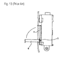
- a conventional electrical junction box 1 to be mounted on a motor vehicle includes a casing body 2. Electrical components such as fuses and relays are detachably mounted on a surface of the casing body 2. A cover 3 is mounted on the casing body 2 to protect the surface to which the electrical components are attached.
- the cover 3 is divided into an upper half member 3a and a lower half member 3b.
- the upper half member 3a covers an area on which electrical components such as fuses accompanied with a high frequency in exchange are mounted.
- the lower half member 3b covers an area on which electrical components such as relays accompanied with a low frequency in exchange are mounted. Only the upper half member 3a is slid upward and removed from the casing body 2 to carry out fuse exchange.
- a cover 6 is rotatably connected through a hinge 5 to a fuse box body 4. By rotating the cover 6 in a direction shown by an arrow upon maintenance, fuses mounted on the fuse box body 4 can be exchanged.
- JP 2002-289171 A has proposed a structure that can limit a rotary range of a hinged cover.
- a hinged battery cover 7 In the hinged battery cover 7, a rotatable cover member 7b is connected through a hinge portion 7a to a stationary cover member 7c and the hinge portion 7a is disposed at a position lower than the members 7b and 7c. As shown in Fig. 14B , the rotary range of the rotatable cover member 7b is minimized.
- the cover can be easily opened or removed from the fuse mounting sections provided on the electrical junction box in order to exchange the fuses.
- cavities in the fuse mounting sections are formed in accordance with the maximum units, including the cases required by options. Consequently, there may be blank cavities (disused cavities) on which the fuses are not mounted. For example, even if ten cavities are provided in the fuse mounting sections, the fuses are mounted in seven cavities and the other three cavities become the blank cavities in which fuses are not mounted.
- connecting terminals to be connected to the fuses must be contained in and secured to the blank cavities. That is, in the case where the connecting terminals to be connected to the fuses are made of bus bars with projecting tabs, in order not to contain the connecting terminals in the three blank cavities that should not be connected to the fuses, it may be possible to prepare the bus bars projecting seven tabs to be connected to only seven fuses. However, it is necessary to prepare two kinds of bus bars, namely the bus bars with seven tabs and the bus bars with ten tabs to be connected to ten fuses. This will not be preferable because a component count will increase. Accordingly, in spite of the number of fuses to be connected, the connecting terminals provided with the tabs corresponding to the number of the cavities must be contained in and secured to the fuse mounting sections.
- connecting terminals to be connected to fuses are solderless terminals attached to distal ends of electrical wires
- solderless terminals it may be possible to contain the solderless terminals in the three blank cavities.
- cavities provided with resin lances for engaging the solderless terminals there is a possibility that different terminals or the like are forcedly contained in and secured to the cavities for the sake of unauthorized use or the like.
- a first object of the present invention is to provide an electrical junction box to be mounted on a motor vehicle that improves an attaching structure of a maintenance cover that is opened upon maintenance such as fuse exchange, minimizes a space required for maintenance so as to reduce a dead space, and enlarges a space for disposing other components. Moreover, it is aim of the present invention to provide an electrical junction box to be mounted on a motor vehicle in which disused blank cavities in fuse mounting sections are not exposed when a maintenance cover is opened, thereby preventing unauthorized use.
- the present invention provides an electrical junction box to be mounted on a motor vehicle, including: a casing body provided concentrically on a surface with a plurality of fuse mounting sections and provided with a maintenance area for exchanging fuses to be attached to the fuse mounting sections; a cover body mounted on and coupled to the casing body at a non-maintenance area except the maintenance area on the casing body; and a maintenance cover separated from the cover body and mounted on the maintenance area on the casing body.
- the maintenance cover is provided on a peripheral wall outer surface with flexible locking frames, wherein an operating portion projects from each of the locking frames.
- a locking pawl is provided on the cover body at a position corresponding to each of the locking frames.
- the maintenance cover is detachably coupled to the locking pawls while deflecting the locking frames.
- the casing body is provided with the maintenance area for fuse exchange that are concentrically provided with the fuse mounting sections and the maintenance cover to be mounted on the maintenance area is separated from the cover body, it is possible to carry out fuse exchange merely by removing the maintenance cover from the cover body.
- the maintenance cover can be detached upward and straightly from the cover body and can be attached downward from the upper position to the cover body.
- the locking frames and locking pawls are detachably coupled to one another.
- the operating portion of each locking frame projects from the peripheral wall outer surface of the maintenance cover. Accordingly, when a working person operates the operating portions to deflect the locking frames, the locking frames on the maintenance cover can be readily coupled to and decoupled from the locking pawls on the casing body.
- the maintenance cover can be attached to and detached from the casing body in the fuse mounting direction.
- the cover has to be slid or rotated by a large amount; but in the present invention it is not necessary to slide or rotate the cover by a large amount. Since the space for attaching and detaching the maintenance cover to and from the casing body can be minimized, it is possible to dispose other components on the area that has been the dead space due to the actions of sliding and rotating the cover in the prior art and it is also possible to arrange the electrical junction box near the vehicle body, thereby effectively utilizing the space in the vehicle body side.
- the maintenance cover of the present invention is not the conventional hinged type cover disclosed in JUM HEI 5 (1993)-31088 A or JP 2002-289171 A , the component mounting area is not reduced on account of interference with the cover, thereby accomplishing the object of the present invention.
- a pair of locking frames is provided on the peripheral wall of the maintenance cover.
- the pair of locking frames is preferably separated away from each other by a distance that a working person can hold the pair of locking frames by one hand.
- the locking pawls on the cover body project from the inner surface of the through-holes opened in the surface of the cover body, and locking frames on the maintenance cover are inserted into the through-holes to engage the locking pawls.
- the through-holes are not limited so long as the through-holes are provided on the inner surfaces with the locking pawls and have spaces in which the locking frames are engaged with and disengaged from the locking pawls while deflecting the locking frames in the through-holes.
- the sides provided with the locking pawls are opposed to each other and a pair of rectangular through-holes is formed to receive the locking frames.
- a plurality of narrow locking pawls or a single wide locking pawl project or projects from the inner surface of each through-hole in order to enhance a coupling force between the locking frame and the locking pawl.
- two narrow locking pawls may be provided on one through-hole while one wide locking pawl may be provided on the other through-hole, it is possible to enhance the coupling force between the locking frame and the locking pawl while preventing a misalignment of the maintenance cover.
- each of the locking frames provided on the maintenance cover includes hinge portions and a rectangular frame portion having right and left frame members, an upper frame member, and a lower frame member.
- the rectangular frame portion is attached through the hinge portions to the peripheral wall outer surface.
- the upper frame member is connected to the right and left frame members so as to serve as an operating portion.
- Each of the lower frame members is adapted to engage each of the locking pawls.
- the lower frame member of each locking frame when the operating portion of each locking frame is pushed inward, the lower frame member of each locking frame is deflected outward around the hinge portions coupling the right and left frame members of each locking frame to the peripheral wall outer surface of the maintenance cover. Accordingly, in order to couple the maintenance cover to the cover body, the lower frame member of each locking frame is inserted into each through-hole in the cover body while pushing inward the operating portion of each locking frame of the maintenance cover, the deflected lower frame member surmounts the locking pawl on the inner surface of the through-hole, and then the lower frame member is engaged with the locking pawl by an elastic recovery force of the operating portion when the operating portion is released.
- each locking frame when the maintenance cover is removed from the cover body, the operating portion of each locking frame is pushed inward, the lower frame member of each locking frame that has been engaged with the locking pawl is deflected outward. The lower frame member is drawn upward from the through-hole to release engagement with the locking pawl.
- the stopper protrusions are provided on the upper wall of the maintenance cover at the position corresponding to the right and left frame members of each locking frame so as to limit the deflection angle of each locking frame.
- the maintenance area adjoins to an outer end edge of the casing body.
- a peripheral wall and an upper wall of the cover body are cut off at positions corresponding to the maintenance area.
- the maintenance cover is mounted on the cut-off portions of the walls.
- the cut-off portion of the peripheral wall of the cover body is continued to an outer peripheral wall of the maintenance cover.
- a pair of opposed side walls is provided on longitudinal opposite ends of the outer peripheral wall.
- Each of the opposed side walls is provided with each of the locking frames.
- the opposed side walls are disposed inside the peripheral wall of the cover body, and each of the locking frames is engaged with each of the locking pawls projecting from inner surfaces of the through-holes in the cover body.
- peripheral wall of the cover body that corresponds to the maintenance area adjacent the outer edge end of the casing body is cut off and the cut-off portion continues to the outer peripheral wall contiguous to the upper wall of the maintenance cover, it is possible to enhance strength of the peripheral wall more than that of a structure in which a thin plate-like peripheral wall of the cover body is not cut off and only the cut-off upper wall is covered with the maintenance cover.
- each of the pair of opposed side walls is provided with the locking frame that continues to the longitudinal opposite ends of the outer peripheral wall of the maintenance cover and the opposed side walls are disposed inside the peripheral wall of the cover body, it is possible to prevent the operating portion of each locking frame from projecting outward from the electrical junction box and a working person can easily operate the operating portion without touching the peripheral components and couple and decouple the maintenance cover to and from the casing body.
- the fuse mounting sections are formed in the maintenance area opened and closed by the maintenance cover.
- the fuse mounting sections are provided with cavities in the case where the fuses are attached to the sections while the sections are not provided with the cavities in the case where the fuses are not attached to the sections.
- the portions in which the cavities are not provided are defined as the additional fuse mounting area.
- the additional fuse mounting area is provided with means for preventing unauthorized access.
- the flat portions and/or grid-like frame portions are provided as preventing means for unauthorized access.
- the additional fuse mounting area is provided on the maintenance area that is opened when the maintenance cover is removed.
- any terminal for unauthorized use cannot be inserted into the additional fuse mounting area. Since the portions to be formed into cavities for additional fuses are previously sectioned, in the case where additional cavities should be formed, only the portions surrounded by the grid-like frames are altered.
- the casing body is provided with the maintenance area for fuse exchange that are concentrically provided with the fuse mounting sections and the maintenance cover to be mounted on the maintenance area is separated from the cover body, it is possible to carry out fuse exchange merely by removing the maintenance cover from the cover body.
- the maintenance cover can be detachably coupled to the cover body by engagement of the locking frames and the locking pawls and the operating portion of each locking frame projects from the peripheral wall outer surface of the maintenance cover. Accordingly, when a working person operates the operating portions to deflect the locking frames to adjust the deflection angle of each locking frame, the locking frames on the maintenance cover can be readily released from the locking pawls on the casing body.
- the maintenance cover can be attached to and detached from the casing body in the fuse mounting direction.
- the space for attaching and detaching the maintenance cover to and from the casing body can be minimized, it is possible to dispose other components on the area that has been the dead space due to the actions of sliding and rotating the cover in the prior art and it is also possible to arrange the electrical junction box near the vehicle body, thereby effectively utilizing the space in the vehicle body side.
- the closing portion and/or the grid-like frame portions are provided on the maintenance area that are exposed outside when the maintenance cover is removed upon maintenance or the fuse mounting sections in which the connecting terminals are contained and fixed, it is possible to prevent other terminals or pins from being forcedly inserted into the fuse mounting sections to conduct the circuits such as bus bars in the electrical junction box, thereby surely preventing unauthorized use.
- Figures 1 to 10 show an embodiment of an electrical junction box to be mounted on a motor vehicle in accordance with the present invention.
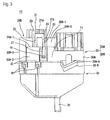
- an electrical junction box 10 to be mounted on a motor vehicle in accordance with the present invention includes a casing body 11, an upper cover 20 to be mounted on an upper part of the casing body 11, and a lower cover 30 to be mounted on a lower part of the casing body 11.
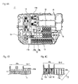
- the casing body 11 contains bus bars (not shown) that are interior circuit members. As shown in Fig. 4A , the casing body 11 is provided on an outer edge end with a maintenance area 11B for fuse exchange. Fuse mounting sections 12 are provided on the maintenance area 11B. The fuse mounting sections 12 contain and secure bus bars with tab terminals T1 ( Fig. 4B ) projecting from a lower surface of the casing body 11 to be connected to the fuses, and solderless or insulation displacement terminals T2 ( Fig. 4C ) to be connected to distal ends of electrical wires.
- the casing body 11 is provided on a top surface with cavities 12a, as shown in Fig. 4B .
- the casing body 11 is not provided with the cavities 12a but is provided with a flat portion 13d to cover the tab terminals T1. This constitutes a structure for preventing an authorized conduction of the tab terminals T1. This portion is defined as an additional fuse mounting area 13-1.
- the casing body 11 is provided on a top surface with cavities 12a, as shown in Fig. 4C .
- the cavities 12a are provided with partitions 12c having lances 12b to contain and engage the solderless terminals T2.
- the casing body 11 is not provided with the cavities 12a but is provided with a grid-like frame 13.
- the grid-like frame 13 includes a plurality of ribs 13a integrally formed on the casing body 11 and a plurality of hollow sections 13b defined between the ribs 13a.
- the hollow sections 13b form through-holes.
- the ribs 13a surrounding the hollow sections 13b are not provided with lances 12b for securing the solderless terminals T2. This constitutes a structure for preventing an authorized accommodation of other terminals.
- These sections are defined as an additional fuse mounting area 13-2.
- bus bars with projecting tab terminals T1 and the solderless terminals T2 are contained in and secured to the fuse mounting sections 12 in the present embodiment, only the bus bars with projecting tab terminals or only the solderless terminals may be contained in and secured to the fuse mounting sections.
- an area except the maintenance area 11B on the surface of the casing body 11 is defined as a non-maintenance area 11A in which relay mounting sections 14 are provided.
- the upper cover 20 includes a cover body 20A to be mounted on the non-maintenance area 11A and a maintenance cover 20B to be mounted on the maintenance area 11B.
- the maintenance cover 20B is separated from the cover body 20A.
- an upper wall 20A-1 and a peripheral wall 20A-2 of the cover body 20A to be mounted on the non-maintenance area 11 A are cut off at positions corresponding to the maintenance area 11B.
- An electronic unit mounting section 20A-4 projects from the surface of the cover body 20A adjacent an end edge that is cut off to define the maintenance area 11B.
- the maintenance cover 20B is disposed on the cut-off space.
- the maintenance cover 20B is formed so that an outer peripheral wall 20B-2 continues to the cut-off portion in a peripheral wall 20A-2 of the cover body 20A upon disposing the maintenance cover 20B.
- a pair of opposed side walls 20B-3 are continued to longitudinal opposite ends of an outer peripheral walls 20B-2 of the maintenance cover 20B.
- a flexible locking frame 21 is provided on an outer surface of each opposed side wall 20B-3.
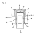
- the locking frame 21 is formed into a rectangular configuration shown in Fig. 8A and Fig. 9 .
- Right and left frame members 21 b of the rectangular locking frame 21 are attached through hinge portions 22 to an outer surface of each opposed side wall 20B-3.
- An upper frame member 21 a of the rectangular locking frame 21 serves as an operating portion for adjusting a deflection angle of the locking frame 21.
- a lower frame member 21 c of the rectangular locking frame 21 serves as a locking portion for engaging locking pawls 26 described after.
- a pair of ribs 23 projects from an upper wall 20B-1 of the maintenance cover 20B so that the ribs 23 interpose the right and left frame members 21 b.
- a pair of stopper protrusions 24 projects from the upper wall 20B-1 of the maintenance cover 20B at positions opposed to the right and left frame members 21b between the ribs 23 to limit a deflection angle of the locking frame 21.
- the cover body 20A is provided with a pair of rectangular through-holes 25 into which the pair of locking frames 21 of the maintenance cover 20B are inserted.
- Each rectangular through-hole 25 is provided on a long side inner surface 25a with locking pawls 26 that the lower frame member 21 c of each locking frame 21 engages.
- two locking pawls 26 are provided on one through-hole 25 while a single wide pawl 26 is provided on the other through-hole 25.
- Vehicle body attaching brackets 20A-5 are provided on a peripheral wall 20A-2 of the cover body 20A.
- Vehicle body attaching brackets 30-5 are provided on the lower cover 30 to be mounted on the brackets 20A-5.
- the brackets 20A-5 are superimposed on the brackets 30-5, bolts are inserted into bolt holes in the brackets, and the cover body 20A and lower cover 30 are attached to vehicle body attaching members (not shown).
- the cover body 20A constituting the upper cover 20 and the lower cover 30 are provided on their peripheral walls with engaging frame portions 27 and 32 while the casing body 11 is provided on a peripheral wall outer surface with engaging pawls 15. By locking the engaging pawls 15 on the engaging frame portions 27 and 32, the casing body 11 is enclosed in the cover body 20A and lower cover 30.
- the maintenance cover 20B is connected to an upper end surface of the lower cover 30 at a lower end of a peripheral wall of the cut-off portion of the cover body 20A.
- Fuses 40 and relays are mounted on the fuse-mounting sections 12 and relay mounting sections14 of the casing body 11. After a wire harness (not shown) is drawn through a wire harness inserting portion 31 into the casing body 11 and is connected to the interior circuit members in the casing body 11, the upper cover 20 and lower cover 30 are assembled on the casing body 11 to form the electrical junction box 10 (see Fig. 3 ).
- the cover body 20A may be assembled on the casing body 11.
- Assembling of the cover body 20A and casing body 11 is carried out by locking the engaging pawls 15 on the peripheral wall of the casing body 11 onto the engaging frame portions 27 on the peripheral wall 20A-2 of the cover body 20A.
- Assembling the lower cover 30 and casing body 11 is carried out by locking the engaging pawls 16 on the peripheral wall of the casing body 11 onto the engaging frame portions 32 on the peripheral wall of the lower cover 30.
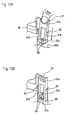
- the maintenance cover 20B is coupled to the cover body 20A firstly by inserting the lower frame member 21 c of each locking frame 21 into each through-hole 25 in the cover body 20A while pushing inward the operating portion 21 a of each locking frame 21 of the maintenance cover 20B, secondly by releasing the operating portion 21a when the lower frame member 21c deflected outward around the hinge portion 22 surmounts the locking pawl 26 on the inner surface 25a of the through-hole, finally by locking the lower frame member 21 c onto the lower and of the locking pawl 26 by an elastic recovery force of the operating portion 21a (see Fig. 10 ).
- the maintenance cover 20B is detachably coupled to the cover body 20A.
- the opposed side walls 20B-3 of the maintenance cover 20B are disposed inside the peripheral wall 20A-2 of the cover body 20A and the outer peripheral wall 20B-2 of the maintenance cover 20B continues to the cut-off portion of the peripheral wall 20A-2 of the cover body 20A.
- the lower frame member 21 c of each locking frame 21 that is engaged with the locking pawl 26 is deflected outward by pushing inward the operating portion 21a of the locking frame 21 and the lower frame member 21c is released from the locking pawl 26 by drawing the lower frame member 21 c from the through-hole 25 while keeping the deflection of the member 21c.
- the maintenance cover 20B can be removed from the cover body 20A in a fuse mounting direction.
- the casing body 11 is provided with the maintenance area 11B for fuse exchange and the maintenance cover 20B to be mounted on the maintenance area 11B is separated from the cover body 20A, it is possible to readily exchange any fuse merely by detaching only the maintenance cover 20B from the casing body 11.
- the maintenance cover 20B and cover body 20A are detachably coupled to each other by engaging the locking pawl 26 with the lower frame member 21 c and the operating portion 21 a of the locking frame 21 projects over the peripheral wall outer surface 20B-2 of the maintenance cover 20B, a working person can easily couple and decouple the locking pawl 26 on the cover body 20A and the lower frame member 21 c of the locking frame 21 to and from each other by adjusting the deflection angle of the locking frame 21.
- the right and left frame members 21 b collide against the stopper protrusions 24 when the lock frame 21 is deflected greatly. Consequently, it is possible to prevent the locking frame 21 from being excessively deflected and to prevent the hinge portions 22 from being broken.
- the additional fuse mounting areas 13-1 and 13-2 are not provided with the cavity 12a but they are provided with the closing flat portion or a grid-like frame portion 13, other terminals or pins cannot be inserted into or secured to any additional fuse mounting areas, even if an unauthorized person intends to insert other terminals or pins into any additional fuse mounting areas. These structures can prevent unauthorized use.
- brackets 20A-5 of the cover body 20B that constitutes the upper cover 20 are superimposed on the brackets 30-5 of the lower cover 30 and they are attached to the vehicle body by the bolts, the casing body 11 cannot be removed from the upper cover 20 and lower cover 30 unless the bolts are removed from the brackets. Accordingly, it is possible to prevent unauthorized access to the non-maintenance area 11A.
- the electrical junction box of the present invention also has an effective countermeasure for unauthorized access.
- peripheral wall 20A-2 of the cover body 20A that corresponds to the maintenance area 11 B adjacent the outer edge end of the casing body 11 is cut off and the cut-off portion continues to the outer peripheral wall 20B-2 contiguous to the upper wall 20B-1 of the maintenance cover 20B, it is possible to enhance strength of the peripheral wall more than that of a structure in which a thin plate-like peripheral wall of the cover body is not cut off and only the cut-off upper wall is covered with the maintenance cover.
- each of the pair of opposed side walls 20B-3 is provided with the locking frame 21 that continues to the longitudinal opposite ends of the outer peripheral wall 20B-2 of the maintenance cover 20B and the opposed side walls 20B-3 are disposed inside the peripheral wall 20A-2 of the cover body 20A, it is possible to prevent the operating portion 21 a of each locking frame 21 from projecting outward from the electrical junction box 10 and a working person can easily operate the operating portion 21 a without touching the peripheral components and couple and decouple the maintenance cover 20B to and from the casing body 11.
- the present invention is not limited to the above embodiment.
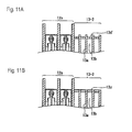
- the additional fuse mounting area 13-1 to be closed by the maintenance cover 20B is integrated with a closing flat portion 13d' bridging the ribs 13a, as shown in Fig. 11A .
- the flat portion 13d' closes the hollow portions 13b, it is possible to surely prevent unauthorized access to the casing body 11 through the hollow portion 13b.
Landscapes
- Engineering & Computer Science (AREA)
- Microelectronics & Electronic Packaging (AREA)
- Connection Or Junction Boxes (AREA)
- Fuses (AREA)
- Casings For Electric Apparatus (AREA)
Applications Claiming Priority (1)
| Application Number | Priority Date | Filing Date | Title |
|---|---|---|---|
| JP2007279539A JP5088090B2 (ja) | 2007-10-26 | 2007-10-26 | 車載用の電気接続箱 |
Publications (3)
| Publication Number | Publication Date |
|---|---|
| EP2056658A2 true EP2056658A2 (de) | 2009-05-06 |
| EP2056658A3 EP2056658A3 (de) | 2009-05-27 |
| EP2056658B1 EP2056658B1 (de) | 2011-02-02 |
Family
ID=40456757
Family Applications (1)
| Application Number | Title | Priority Date | Filing Date |
|---|---|---|---|
| EP20080162013 Ceased EP2056658B1 (de) | 2007-10-26 | 2008-08-07 | Elektroanschlusskasten zur Montage auf einem Kraftfahrzeug |
Country Status (4)
| Country | Link |
|---|---|
| EP (1) | EP2056658B1 (de) |
| JP (1) | JP5088090B2 (de) |
| CN (1) | CN101420106B (de) |
| DE (1) | DE602008004810D1 (de) |
Cited By (6)
| Publication number | Priority date | Publication date | Assignee | Title |
|---|---|---|---|---|
| CN103287355A (zh) * | 2012-03-02 | 2013-09-11 | 中通客车控股股份有限公司 | 一种车辆中央控制配电装置 |
| EP2432091A4 (de) * | 2009-05-14 | 2014-06-11 | Yazaki Corp | Klammerstruktur für einen elektrischen anschlusskasten |
| CN106114417A (zh) * | 2016-08-31 | 2016-11-16 | 重庆五洲龙新能源汽车有限公司 | 纯电动客车的低压配电盒 |
| US9672961B2 (en) | 2012-08-30 | 2017-06-06 | Yazaki Corporation | Bus bar module accommodating part structure |
| WO2019006278A1 (en) * | 2017-06-30 | 2019-01-03 | Sumitomo Wiring Systems, Ltd. | JUNCTION BOX ASSEMBLY WITH GATE-SHAPED TERMINAL COVER RESTRAINT SYSTEM AND REMOVABLE GATE-SHAPE TERMINAL COVER |
| US11600977B2 (en) | 2020-07-29 | 2023-03-07 | Yazaki Corporation | Resin structure |
Families Citing this family (12)
| Publication number | Priority date | Publication date | Assignee | Title |
|---|---|---|---|---|
| JP5805997B2 (ja) * | 2011-05-24 | 2015-11-10 | 矢崎総業株式会社 | 電気接続箱 |
| JP5994142B2 (ja) * | 2012-11-14 | 2016-09-21 | 矢崎総業株式会社 | 電気接続箱 |
| JP2015033221A (ja) * | 2013-08-02 | 2015-02-16 | 矢崎総業株式会社 | 電気接続箱 |
| JP6045075B2 (ja) * | 2013-09-30 | 2016-12-14 | 矢崎総業株式会社 | 電気接続箱 |
| JP6441137B2 (ja) * | 2015-03-19 | 2018-12-19 | 矢崎総業株式会社 | 電気接続箱及びワイヤハーネス |
| JP6525396B2 (ja) * | 2016-06-21 | 2019-06-05 | 住友電装株式会社 | 電気接続箱 |
| JP6907043B2 (ja) * | 2017-06-16 | 2021-07-21 | 矢崎総業株式会社 | 電気接続箱 |
| JP2019125466A (ja) * | 2018-01-16 | 2019-07-25 | Asti株式会社 | ヒューズボックス |
| CN109890164B (zh) * | 2019-03-18 | 2024-03-26 | 新乡市光明电器有限公司 | 强密封性电气控制盒 |
| JP7167846B2 (ja) * | 2019-05-15 | 2022-11-09 | 株式会社オートネットワーク技術研究所 | 電気接続箱 |
| JP2021136700A (ja) * | 2020-02-21 | 2021-09-13 | 住友電装株式会社 | 電気接続箱 |
| JP7512935B2 (ja) | 2021-03-25 | 2024-07-09 | 横河電機株式会社 | カバー及び電子機器 |
Citations (3)
| Publication number | Priority date | Publication date | Assignee | Title |
|---|---|---|---|---|
| JPH0531088U (ja) | 1991-09-30 | 1993-04-23 | 矢崎総業株式会社 | 車両用ヒユーズボツクス |
| JP2000316220A (ja) | 1999-04-28 | 2000-11-14 | Sumitomo Wiring Syst Ltd | 電気接続箱 |
| JP2002289171A (ja) | 2001-03-26 | 2002-10-04 | Yazaki Corp | バッテリカバー |
Family Cites Families (8)
| Publication number | Priority date | Publication date | Assignee | Title |
|---|---|---|---|---|
| JPH07131917A (ja) * | 1993-11-02 | 1995-05-19 | Yazaki Corp | ロック機構 |
| JP3153736B2 (ja) * | 1995-06-23 | 2001-04-09 | 矢崎総業株式会社 | ボックス |
| JP3248406B2 (ja) * | 1995-09-26 | 2002-01-21 | 富士通株式会社 | 端子盤 |
| JP3087667B2 (ja) * | 1996-11-25 | 2000-09-11 | 住友電装株式会社 | 自動車用の電気接続箱 |
| JP3463632B2 (ja) * | 1999-12-02 | 2003-11-05 | 住友電装株式会社 | 電気接続箱 |
| KR100516513B1 (ko) * | 2004-02-19 | 2005-09-26 | 타이코에이엠피 주식회사 | 차량용 정션박스 및 그 조립방법 |
| JP2005251787A (ja) * | 2004-03-01 | 2005-09-15 | Calsonic Kansei Corp | 基板モジュールの防塵構造 |
| CN100566062C (zh) * | 2004-03-17 | 2009-12-02 | 住友电装株式会社 | 电接线盒 |
-
2007
- 2007-10-26 JP JP2007279539A patent/JP5088090B2/ja not_active Expired - Fee Related
-
2008
- 2008-08-07 EP EP20080162013 patent/EP2056658B1/de not_active Ceased
- 2008-08-07 DE DE200860004810 patent/DE602008004810D1/de active Active
- 2008-10-24 CN CN2008101729189A patent/CN101420106B/zh not_active Expired - Fee Related
Patent Citations (3)
| Publication number | Priority date | Publication date | Assignee | Title |
|---|---|---|---|---|
| JPH0531088U (ja) | 1991-09-30 | 1993-04-23 | 矢崎総業株式会社 | 車両用ヒユーズボツクス |
| JP2000316220A (ja) | 1999-04-28 | 2000-11-14 | Sumitomo Wiring Syst Ltd | 電気接続箱 |
| JP2002289171A (ja) | 2001-03-26 | 2002-10-04 | Yazaki Corp | バッテリカバー |
Cited By (8)
| Publication number | Priority date | Publication date | Assignee | Title |
|---|---|---|---|---|
| EP2432091A4 (de) * | 2009-05-14 | 2014-06-11 | Yazaki Corp | Klammerstruktur für einen elektrischen anschlusskasten |
| CN103287355A (zh) * | 2012-03-02 | 2013-09-11 | 中通客车控股股份有限公司 | 一种车辆中央控制配电装置 |
| CN103287355B (zh) * | 2012-03-02 | 2016-05-11 | 中通客车控股股份有限公司 | 一种车辆中央控制配电装置 |
| US9672961B2 (en) | 2012-08-30 | 2017-06-06 | Yazaki Corporation | Bus bar module accommodating part structure |
| CN106114417A (zh) * | 2016-08-31 | 2016-11-16 | 重庆五洲龙新能源汽车有限公司 | 纯电动客车的低压配电盒 |
| CN106114417B (zh) * | 2016-08-31 | 2018-01-26 | 重庆五洲龙新能源汽车有限公司 | 纯电动客车的低压配电盒 |
| WO2019006278A1 (en) * | 2017-06-30 | 2019-01-03 | Sumitomo Wiring Systems, Ltd. | JUNCTION BOX ASSEMBLY WITH GATE-SHAPED TERMINAL COVER RESTRAINT SYSTEM AND REMOVABLE GATE-SHAPE TERMINAL COVER |
| US11600977B2 (en) | 2020-07-29 | 2023-03-07 | Yazaki Corporation | Resin structure |
Also Published As
| Publication number | Publication date |
|---|---|
| JP5088090B2 (ja) | 2012-12-05 |
| CN101420106B (zh) | 2011-09-07 |
| CN101420106A (zh) | 2009-04-29 |
| EP2056658B1 (de) | 2011-02-02 |
| JP2009112078A (ja) | 2009-05-21 |
| DE602008004810D1 (de) | 2011-03-17 |
| EP2056658A3 (de) | 2009-05-27 |
Similar Documents
| Publication | Publication Date | Title |
|---|---|---|
| EP2056658B1 (de) | Elektroanschlusskasten zur Montage auf einem Kraftfahrzeug | |
| US6796808B2 (en) | Electric junction box | |
| US7098397B2 (en) | Housing arrangement with at least one junction box | |
| EP2124239A1 (de) | Mehrfachsicherungsvorrichtung für ein fahrzeug | |
| JP2013226019A (ja) | 電気接続箱 | |
| WO2007147492A1 (de) | Electrical connector | |
| US20150305184A1 (en) | Locking structure between member to be supported and supporting body | |
| KR101344231B1 (ko) | 전기 정션박스의 조립구조 | |
| EP2715765B1 (de) | Vorrichtung zum befestigen von sicherungen und elektrischer verbindungskasten | |
| EP2190075B1 (de) | Mehrfachverbindervorrichtung mit Verbindungssequenzierungssperrmechanismus | |
| CN207559179U (zh) | 汇流条连接用连接器和包含该连接器的电池组 | |
| US20100173532A1 (en) | Component position assurance element for a power distribution block | |
| JP2004080917A (ja) | ジャンクションボックス | |
| JP4145747B2 (ja) | 電気接続箱 | |
| CN214189554U (zh) | 车辆仪表区域电器盒及车辆 | |
| EP3037304B1 (de) | Elektrischer verteilerkasten für fahrzeug | |
| US12057687B2 (en) | Electrical junction box | |
| JP3269034B2 (ja) | 電気コネクタ | |
| JP2011055630A (ja) | 電気接続箱 | |
| EP2347472B1 (de) | Verfahren und einrichtung zur ermöglichung der verbindung mit einer batterie | |
| KR101001887B1 (ko) | 차량용 박스 | |
| CN224020693U (zh) | 一种继电器模块、配电组件、电池装置及用电设备 | |
| CN215421211U (zh) | 一种应用于标准机箱的线缆引出结构 | |
| EP4205245B1 (de) | Verbinderhalteklemme | |
| JP2957063B2 (ja) | 電気接続箱 |
Legal Events
| Date | Code | Title | Description |
|---|---|---|---|
| PUAI | Public reference made under article 153(3) epc to a published international application that has entered the european phase |
Free format text: ORIGINAL CODE: 0009012 |
|
| PUAL | Search report despatched |
Free format text: ORIGINAL CODE: 0009013 |
|
| AK | Designated contracting states |
Kind code of ref document: A2 Designated state(s): AT BE BG CH CY CZ DE DK EE ES FI FR GB GR HR HU IE IS IT LI LT LU LV MC MT NL NO PL PT RO SE SI SK TR |
|
| AX | Request for extension of the european patent |
Extension state: AL BA MK RS |
|
| AK | Designated contracting states |
Kind code of ref document: A3 Designated state(s): AT BE BG CH CY CZ DE DK EE ES FI FR GB GR HR HU IE IS IT LI LT LU LV MC MT NL NO PL PT RO SE SI SK TR |
|
| AX | Request for extension of the european patent |
Extension state: AL BA MK RS |
|
| 17P | Request for examination filed |
Effective date: 20090914 |
|
| 17Q | First examination report despatched |
Effective date: 20091202 |
|
| AKX | Designation fees paid |
Designated state(s): DE |
|
| GRAP | Despatch of communication of intention to grant a patent |
Free format text: ORIGINAL CODE: EPIDOSNIGR1 |
|
| GRAS | Grant fee paid |
Free format text: ORIGINAL CODE: EPIDOSNIGR3 |
|
| GRAA | (expected) grant |
Free format text: ORIGINAL CODE: 0009210 |
|
| AK | Designated contracting states |
Kind code of ref document: B1 Designated state(s): DE |
|
| REF | Corresponds to: |
Ref document number: 602008004810 Country of ref document: DE Date of ref document: 20110317 Kind code of ref document: P |
|
| REG | Reference to a national code |
Ref country code: DE Ref legal event code: R096 Ref document number: 602008004810 Country of ref document: DE Effective date: 20110317 |
|
| PLBE | No opposition filed within time limit |
Free format text: ORIGINAL CODE: 0009261 |
|
| STAA | Information on the status of an ep patent application or granted ep patent |
Free format text: STATUS: NO OPPOSITION FILED WITHIN TIME LIMIT |
|
| 26N | No opposition filed |
Effective date: 20111103 |
|
| REG | Reference to a national code |
Ref country code: DE Ref legal event code: R097 Ref document number: 602008004810 Country of ref document: DE Effective date: 20111103 |
|
| REG | Reference to a national code |
Ref country code: DE Ref legal event code: R084 Ref document number: 602008004810 Country of ref document: DE |
|
| PGFP | Annual fee paid to national office [announced via postgrant information from national office to epo] |
Ref country code: DE Payment date: 20180724 Year of fee payment: 11 |
|
| REG | Reference to a national code |
Ref country code: DE Ref legal event code: R119 Ref document number: 602008004810 Country of ref document: DE |
|
| PG25 | Lapsed in a contracting state [announced via postgrant information from national office to epo] |
Ref country code: DE Free format text: LAPSE BECAUSE OF NON-PAYMENT OF DUE FEES Effective date: 20200303 |