EP2018970A2 - Flüssigkeitsausgabevorrichtung, Bildgebungsvorrichtung und Mengenbeurteilungsverfahren für einen Flüssigkeitsspeicher - Google Patents
Flüssigkeitsausgabevorrichtung, Bildgebungsvorrichtung und Mengenbeurteilungsverfahren für einen Flüssigkeitsspeicher Download PDFInfo
- Publication number
- EP2018970A2 EP2018970A2 EP08013178A EP08013178A EP2018970A2 EP 2018970 A2 EP2018970 A2 EP 2018970A2 EP 08013178 A EP08013178 A EP 08013178A EP 08013178 A EP08013178 A EP 08013178A EP 2018970 A2 EP2018970 A2 EP 2018970A2
- Authority
- EP
- European Patent Office
- Prior art keywords
- liquid
- chamber
- pressure
- ink
- gas
- Prior art date
- Legal status (The legal status is an assumption and is not a legal conclusion. Google has not performed a legal analysis and makes no representation as to the accuracy of the status listed.)
- Granted
Links
Images


Classifications
-
- B—PERFORMING OPERATIONS; TRANSPORTING
- B41—PRINTING; LINING MACHINES; TYPEWRITERS; STAMPS
- B41J—TYPEWRITERS; SELECTIVE PRINTING MECHANISMS, i.e. MECHANISMS PRINTING OTHERWISE THAN FROM A FORME; CORRECTION OF TYPOGRAPHICAL ERRORS
- B41J2/00—Typewriters or selective printing mechanisms characterised by the printing or marking process for which they are designed
- B41J2/005—Typewriters or selective printing mechanisms characterised by the printing or marking process for which they are designed characterised by bringing liquid or particles selectively into contact with a printing material
- B41J2/01—Ink jet
- B41J2/17—Ink jet characterised by ink handling
- B41J2/175—Ink supply systems ; Circuit parts therefor
- B41J2/17566—Ink level or ink residue control
-
- B—PERFORMING OPERATIONS; TRANSPORTING
- B41—PRINTING; LINING MACHINES; TYPEWRITERS; STAMPS
- B41J—TYPEWRITERS; SELECTIVE PRINTING MECHANISMS, i.e. MECHANISMS PRINTING OTHERWISE THAN FROM A FORME; CORRECTION OF TYPOGRAPHICAL ERRORS
- B41J2/00—Typewriters or selective printing mechanisms characterised by the printing or marking process for which they are designed
- B41J2/005—Typewriters or selective printing mechanisms characterised by the printing or marking process for which they are designed characterised by bringing liquid or particles selectively into contact with a printing material
- B41J2/01—Ink jet
- B41J2/17—Ink jet characterised by ink handling
- B41J2/175—Ink supply systems ; Circuit parts therefor
- B41J2/17503—Ink cartridges
- B41J2/17556—Means for regulating the pressure in the cartridge
-
- B—PERFORMING OPERATIONS; TRANSPORTING
- B41—PRINTING; LINING MACHINES; TYPEWRITERS; STAMPS
- B41J—TYPEWRITERS; SELECTIVE PRINTING MECHANISMS, i.e. MECHANISMS PRINTING OTHERWISE THAN FROM A FORME; CORRECTION OF TYPOGRAPHICAL ERRORS
- B41J2/00—Typewriters or selective printing mechanisms characterised by the printing or marking process for which they are designed
- B41J2/005—Typewriters or selective printing mechanisms characterised by the printing or marking process for which they are designed characterised by bringing liquid or particles selectively into contact with a printing material
- B41J2/01—Ink jet
- B41J2/17—Ink jet characterised by ink handling
- B41J2/175—Ink supply systems ; Circuit parts therefor
- B41J2/17596—Ink pumps, ink valves
Definitions
- the present invention relates to a liquid ejection apparatus, an image forming apparatus and a liquid storage amount judgment method, and more particularly, to a liquid ejection apparatus used in an inkjet type recording apparatus.
- the invention disclosed in Japanese Patent Application Publication No. 2003-300331 comprises: an ink bag connected to a recording head, a seal device which hermetically encloses the ink bag, a suctioning device which performs suctioning to create a negative pressure in the space between the seal device and the ink bag, and a negative pressure determination device which determines the pressure of the space between the seal device and the ink bag.
- the negative pressure determination device determines the state of negative pressure change in the space between the seal device and the ink bag when a negative pressure is created by the suctioning device, so that the residual amount of ink in the ink bag is determined. Then, the back pressure of the recording head is controlled on the basis of the residual amount of ink thus determined.
- the invention described below has been disclosed as a device for determining the liquid pressure of the ink, and the remaining amount of ink, inside a recording head.
- one portion of the wall of an ink supply channel inside a recording head is constituted by a flexible film, and by determining the displacement of this flexible film, the pressure and remaining amount of the ink inside the recording head are determined.
- Japanese Patent Application Publication No. 2003-300331 determines the pressure in the space between a seal device and an ink bag by means of a negative pressure determination device, it does not determine the pressure of the ink inside the ink bag. Therefore, when determining the remaining amount of ink, it is necessary to halt the ejection of ink from the recording head and set the pressure of the ink inside the ink bag to a uniform pressure. Consequently, the accuracy of determining the remaining amount of ink declines when ink is being ejected from the recording head, and there is a possibility that the back pressure of the recording head cannot be controlled stably.
- the flexible film deteriorates due to the application of repeated displacement of the flexible film.
- the determination accuracy of the ink pressure and the determination accuracy of the remaining amount of ink decline.
- the load applied to the flexible film becomes larger and there is a possibility that deterioration will occur more rapidly.
- the present invention has been contrived in view of the foregoing circumstances, an object thereof being to provide a liquid ejection apparatus in which the judgment accuracy of the amount of liquid stored in a liquid chamber can be raised and the back pressure can be controlled in a stable fashion.
- the present invention is directed to a liquid ejection apparatus, comprising: a sub tank having a liquid chamber which stores liquid, a gas chamber which fills with gas, and a flexible film which divides the liquid chamber from the gas chamber; a liquid tank which is connected to the liquid chamber and stores the liquid; a liquid conveyance device which conveys the liquid between the liquid chamber and the liquid tank; an ejection head connected to the liquid chamber; a control device which carries out control in such a manner that pressure in the gas chamber is controlled to control back pressure of the liquid in the ejection head; a liquid pressure determination device which determines pressure in the liquid chamber; a gas pressure determination device which determines the pressure in the gas chamber; and a liquid storage amount judgment device which judges whether or not an amount of the liquid stored in the liquid chamber is within a tolerable range in which the back pressure of the liquid in the ejection head can be controlled, according to a gas-liquid pressure differential which is a difference between the pressure of the liquid chamber determined by the liquid pressure
- the respective pressures of the liquid chamber and the gas chamber are determined, and the pressure differential between the liquid chamber and the gas chamber is used to judge whether or not the amount of liquid stored in the liquid chamber is within a tolerable range in which the back pressure can be controlled. Therefore, even in circumstances where the liquid storage amount in the liquid chamber changes, such as during replenishment of liquid or during consumption of liquid, it is possible to enhance the judgment accuracy of the liquid storage amount in the liquid chamber.
- the liquid storage amount judgment device sets a range of a gas-liquid pressure differential in which the flexible film can bend freely, and judges that the amount of liquid stored in the liquid chamber reaches a limit value of the tolerable range, when the gas-liquid pressure differential exceeds a limit value of the set range.
- the liquid conveyance device carries out replenishment supply to convey the liquid from the liquid tank to the liquid chamber, and return supply to convey the liquid from the liquid chamber to the liquid tank; and when the liquid storage amount judgment device judges that the amount of liquid stored in the liquid chamber has reached an upper limit value of the tolerable range due to the replenishment supply, the control device carries out the control in such a manner that the liquid conveyance device halts the replenishment supply and carries out the return supply.
- control device carries out the control in such a manner that a speed of the liquid conveyed from the liquid tank to the liquid chamber during the replenishment supply is substantially uniform or is varied periodically.
- the liquid droplet ejection apparatus further comprises a flexible film deterioration judgment device which determines liquid replenishment time that is a time period required for the amount of liquid stored in the liquid chamber to vary from a lower limit value to an upper limit value of the tolerable range by means of the replenishment supply, and which judges a state of deterioration of the flexible film according to the determined liquid replenishment time.
- a flexible film deterioration judgment device which determines liquid replenishment time that is a time period required for the amount of liquid stored in the liquid chamber to vary from a lower limit value to an upper limit value of the tolerable range by means of the replenishment supply, and which judges a state of deterioration of the flexible film according to the determined liquid replenishment time.
- the flexible film deterioration judgment device judges that a lifespan of the flexible film is reached in terms of the state of deterioration of the flexible film.
- the liquid ejection apparatus further comprises a warning device which issues a warning that replacement timing of the flexible film is reached, when the flexible film deterioration judgment device judges that the lifespan of the flexible film is reached in terms of the state of deterioration of the flexible film.
- control device controls an amount of the liquid conveyed in the return supply in accordance with the liquid replenishment time.
- the present invention is also directed to an image forming apparatus comprising any one of the above-described liquid ejection apparatuses.
- the present invention is also directed to a liquid storage amount judgment method of judging an amount of liquid stored in a liquid chamber of a sub tank having the liquid chamber which stores the liquid, a gas chamber which fills with gas, and a flexible film which divides the liquid chamber from the gas chamber, the liquid storage amount judgment method comprising: a liquid pressure determination step of determining pressure in the liquid chamber; a gas pressure determination step of determining pressure in the gas chamber; a liquid storage amount judgment step of judging whether or not an amount of the liquid stored in the liquid chamber is within a tolerable range in which back pressure of the liquid in an ejection head connected to the liquid chamber can be controlled by controlling the pressure in the gas chamber, according to a gas-liquid pressure differential which is a difference between the pressure of the liquid chamber determined in the liquid pressure determination step and the pressure of the gas chamber determined in the gas pressure determination step.
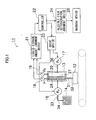
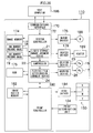
- Fig. 1 is a general schematic diagram of a liquid ejection apparatus according to an embodiment of the present invention.
- the liquid ejection apparatus according to the embodiment of the present invention comprises, for example, a recording head 12 (ejection head), a sub tank 13, an ink tank 14 (liquid tank), an ink pump 16 (liquid conveyance device), a gas pump 17, an ink chamber pressure gauge 18 (liquid pressure determination device), a gas chamber pressure gauge 19 (gas pressure determination device), a liquid storage amount judgment device 21, a controller 22 (control device), a drive device 23, a flexible film deterioration judgment device 24, a warning device 26, and the like.
- Nozzles 151 which are described below are formed in the recording head 12, and ink is ejected from these nozzles 151. These elements are described in more detail below.
- the sub tank 13 comprises a flexible film 27 provided inside a tank which forms a hermetically sealed container, and the interior of the tank is divided into an ink chamber 28 (liquid chamber) and a gas chamber 29 by means of the flexible film 27.
- the flexible film 27 may be a film membrane, or an elastic membrane, or the like.
- the ink chamber 28 is connected to the recording head 12 by a connection channel 32, via a valve 31, and it is also connected to the ink tank 14 by a connection channel 34 via the ink pump 16 and a valve 33. Furthermore, the pressure of the ink inside the ink chamber 28 is determined by the ink chamber pressure gauge 18.
- the gas chamber 29 is connected to the gas pump 17 via the connection channel 36. Moreover, the pressure of the gas inside the gas chamber 29 is determined by the gas chamber pressure gauge 19.
- the pressure P 1 of the ink chamber 28 is determined by the ink chamber pressure gauge 18, and the inflow and outflow of gas in the gas chamber 29 created by the gas pump 17 is controlled in order to control the back pressure in such a manner that the pressure P 1 of the ink chamber 28 becomes a prescribed back pressure value. Consequently, a back pressure is applied to the ink in the recording head 12.
- the pressure of the sub tank 13 can be adjusted accordingly, and the sub tank 13 is provided above the recording head 12 and the connection channel 32 between the sub tank 13 and the recording head 12 can be shortened in order to reduce any variations in the back pressure caused by variation in the pressure loss in the flow channel.
- the ink tank 14 stores ink for replenishment of the ink chamber 28 of the sub tank 13.
- the liquid storage amount judgment device 21 is a device of determining the amount of ink stored inside the ink chamber 28 of the sub tank 13, on the basis of the ink pressure determination data obtained from the ink chamber pressure gauge 18, and the gas pressure determination data obtained from the gas chamber pressure gauge 19.
- the controller 22 controls the pressure in the gas chamber 29 so as to control the back pressure of the ink inside the recording head 12. Furthermore, it creates drive data to be supplied to the drive device 23 to control the ink pump 16 and the gas pump 17, on the basis of the data about the amount of ink stored in the ink chamber 28 of the sub tank 13, as judged by the liquid storage amount judgment device 21. Furthermore, the drive data for the ink pump 16 thus created is supplied to the flexible film deterioration judgment device 24.
- the flexible film deterioration judgment device 24 is a device of judging the state of deterioration of the flexible film 27, on the basis of the drive data for the ink pump 16 created by the controller 22 and supplied to the drive device 23, and of supplying data on the judgment results to the warning device 26.
- the warning device 26 is a device which issues a warning about the replacement timing of the flexible film 27, and it may be, for instance, a display device, an alarm source generating device, or the like.
- Fig. 2 is a flowchart of the judgment of the ink storage amount in the ink chamber 28 of the sub tank 13. As shown in Fig. 2 , when the flowchart is started, firstly, the pressure P 1 inside the ink chamber 28 is determined by the ink chamber pressure gauge 18, and the pressure P 2 in the gas chamber 29 is determined by the gas chamber pressure gauge 19 (step S2-1).
- the liquid storage amount judgment device 21 determines the pressure differential (P 1 - P 2 ), which is the gas/liquid pressure difference, on the basis of the determination data for the pressure P 1 in the ink chamber 28 and the determination data for the pressure P 2 in the gas chamber 29.
- Fig. 3 is a diagram showing the relationship among the ink volume and the pressure P 1 inside the ink chamber 28 and the pressure P 2 inside the gas chamber 29, when a film membrane is used as the flexible film 27.
- Fig. 4 shows the state of the pressure differential between the pressure P 1 and the pressure P 2 which changes in response to the change in the ink volume, as shown in Fig. 3 . In the present embodiment, judgment is made on the basis of this pressure differential (P 1 - P 2 ).
- the tension in the flexible film 27 increases, and when the flexible film 27 reaches a limit state where it has stretched to an extent where it can no longer bend freely (a state at the limit of the range where the back pressure of the ink inside the recording head 12 can be controlled by controlling the pressure in the gas chamber 29 and causing the flexible film 27 to bend freely), then an "ink empty” or "ink full” status is determined.
- the pressure differential may also be defined as (P 2 - P 1 ).
- P min is a limit value at which the flexible film 27 is stretched and can no longer bend freely, and it indicates the lower limit value of the tolerable range of the ink volume in the ink chamber 28 in which the back pressure of the ink inside the recording head 12 can be controlled.
- the ink volume in the ink chamber 28 is equal to or lower than the lowest value of the tolerable range in which the back pressure of the ink inside the recording head 12 can be controlled, and the status is judged as an "ink empty" status (step S2-3).
- the state of the flexible film 27 in the sub tank 13 at which it is judged as such an "ink empty” status is represented by A 1 and B 1 in Fig. 4 .
- a 1 and B 1 in Fig. 4 the pressure of the gas chamber 29 becomes greater, and the amount of ink inside the ink chamber 28 declines.
- the flexible film 27 is pressed toward the ink chamber 28 and is stretched and becomes unable to bend freely.
- P max is a limit value at which the flexible film 27 is stretched and can no longer bend freely, and it indicates the upper limit value of the tolerable range of the ink volume in the ink chamber 28 in which the back pressure of the ink inside the recording head 12 can be controlled.
- step S2-5) If the condition (P 1 - P 2 ) ⁇ P max is satisfied, then the ink volume is equal to or exceeds the upper limit value of the tolerable range in which the back pressure of the ink inside the recording head 12 can be controlled, and therefore the status is judged as an "ink full" status (step S2-5).
- the state of the flexible film 27 in the sub tank 13 at which it is judged as an "ink full” status is represented by D 1 and E 1 in Fig. 4 . As shown by D 1 and E 1 in Fig. 4 , the pressure of the gas chamber 29 becomes smaller, and the amount of ink inside the ink chamber 28 increases. The flexible film 27 is pressed toward the gas chamber 29 and is stretched and becomes unable to bend freely.
- step S2-6) If the condition (P 1 - P 2 ) ⁇ P max is not satisfied, then it is judged that the ink volume is within the tolerable range in which the back pressure of the ink inside the recording head 12 can be controlled (step S2-6).
- the state of the flexible film 27 in the sub tank 13 when it is judged that the ink volume is within the tolerable range in which the back pressure of the ink inside the recording head 12 can be controlled is represented by C 1 in Fig. 4 .
- the ink chamber 28 and the gas chamber 29 are separated by the flexible film 27 in such a manner that the volume of ink inside the ink chamber 28 becomes a volume which allows the back pressure of the ink inside the recording head 12 to be controlled.
- the tolerable range is set as the ink volume range in which the pressure P 1 in the ink chamber 28 and the pressure P 2 in the gas chamber 29 assume the set back pressure value
- the tolerable range in the case of an ink volume which is lower than the tolerable range, it is not possible to control the pressure P 1 in the ink chamber 28 and the pressure P 2 in the gas chamber 29 to the set back pressure value, and hence the pressure P 1 in the ink chamber 28 becomes a negative pressure value which is larger than the set back pressure value, while the pressure P 2 in the gas chamber 29 becomes a value which is to the positive pressure side of the set back pressure value.
- the ink volume is greater than the tolerable range, then it is not possible to control the pressure P 1 in the ink chamber 28 or the pressure P 2 in the gas chamber 29, to the set back pressure value, and the pressure P 1 in the ink chamber 28 becomes a value which is positive with respect to the set back pressure value, while the pressure P 2 in the gas chamber 29 becomes a negative pressure which is larger than the set back pressure value.
- the amount of change (graph gradient) of the pressure P 2 in the gas chamber 29 with respect to the ink volume is greater than the amount of change (graph gradient) of the pressure P 1 in the ink chamber 28 with respect to the ink volume.
- the pressure differential (P 1 - P 2 ) is thought to give better determination sensitivity and improve the judgment accuracy, and consequently judgment is made by determining the pressure differential (P 1 - P 2 ).
- the following merits are thought to be obtained by making judgment through determining the pressure differential (P 1 - P 2 ).
- the pressure differential P 1 - P 2
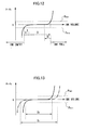
- a sudden pressure change has occurred in the pressure P 1 inside the ink chamber 28 ( Fig. 5(a) ) due to disturbance such as the pulsating action of the ink pump 16, or the like, then this is propagated also to the gas chamber 29 and a sudden pressure change occurs in the pressure P 2 in the gas chamber 29 also ( Fig. 5(b) ).
- the ink storage amount in the ink chamber 28 of the sub tank 13 is determined on the basis of the pressure P 1 in the ink chamber 28 only, or the pressure P 2 in the gas chamber 29 only, then as shown in Fig.
- the pressure P 1 in the ink chamber 28 is determined with respect to each time. Therefore, in circumstances where there is a change in the ink volume in the ink chamber 28, such as during replenishment of ink from the ink tank 14 to the ink chamber 28, or during consumption of ink from the ink chamber 28, or the like, then there is a merit in that it is possible that an "ink empty” status, an "ink full” status, and a status where the ink volume is within a tolerable range which allows the back pressure of the ink to be controlled are determined.
- the judgment process of the ink storage amount in the ink chamber 28 shown in Fig. 2 is carried out when the image forming apparatus comprising the liquid ejection apparatus is started up, during image formation (printing), and during maintenance.
- Fig. 6 is a diagram showing the relationship among the ink volume in the ink chamber 28 and the pressure P 1 inside the ink chamber 28 and the pressure P 2 inside the gas chamber 29, when an elastic membrane is used as the flexible film 27.
- Fig. 7 shows the state of the pressure differential between the pressure P 1 and the pressure P 2 which changes in response to the change in the ink volume as shown in Fig. 6 .
- the method of judging the ink storage amount in the ink chamber 28 of the sub tank 13 is shown in Fig. 2 and is similar to that when a film membrane is used as the flexible film 27.
- the state of the flexible film 27 in the sub tank 13 when it is judged as an "ink empty" status is represented by A 2 and B 2 in Fig. 7 .
- the pressure of the gas chamber 29 becomes greater, and the amount of ink inside the ink chamber 28 declines.
- the flexible film 27 is pressed toward the ink chamber 28 and is stretched and becomes unable to bend freely.
- the state of the flexible film 27 in the sub tank 13 when it is judged as an "ink full" status is represented by D 2 and E 2 in Fig. 7 .
- the pressure of the gas chamber 29 becomes smaller, and the amount of ink inside the ink chamber 28 increases.
- the flexible film 27 is pressed toward the gas chamber 29 and is stretched and becomes unable to bend freely.
- the state of the flexible film 27 in the sub tank 13 when it is judged that the pressure differential is within the tolerable range in which the back pressure of the ink inside the recording head 12 can be controlled is represented by C 2 in Fig. 7 .
- the ink chamber 28 and the gas chamber 29 are separated by the flexible film 27 in such a manner that the volume of ink inside the ink chamber 28 becomes a volume which allows the back pressure of the ink inside the recording head 12 to be controlled.
- Fig. 8 is a flowchart diagram of a method of controlling the amount of ink in the ink chamber 28 when the status is judged as an "ink empty" status by the liquid storage amount judgment device 21.
- Fig. 9 is a diagram showing the procedure of controlling the ink volume in the ink chamber 28, together with the relationship between the pressure difference (P 1 - P 2 ) and the ink volume in the ink chamber 28.
- a case is considered where the status is judged to be "ink empty" by the liquid storage amount judgment device 21 after the start of the procedure (step S8-1).
- the ink pump 16 is driven in the forward direction, and ink is conveyed from the ink tank 14 into the ink chamber 28 in the sub tank 13 (replenishment conveyance) (step S8-2).
- the speed of this conveyance may be controlled uniformly, or it may be controlled so as to change periodically. If the speed is controlled to a uniform speed, then the ink can be conveyed stably from the ink tank 14 to the ink chamber 28. Furthermore, by controlling the speed so as to change periodically, it is possible to apply a periodic variation to the flexible film 27 and therefore any bubbles or foreign material adhering thereto becomes more liable to be detached.
- the pressure P 1 in the ink chamber 28 is determined by the ink chamber pressure gauge 18, and the pressure P 2 in the gas chamber 29 is determined by the gas chamber pressure gauge 19 (step S8-3).
- the liquid storage amount judgment device 21 determines the pressure differential (P 1 - P 2 ) on the basis of the determination data for the pressure P 1 in the ink chamber 28 and the determination data for the pressure P 2 in the gas chamber 29. Then, in respect of the determined pressure differential (P 1 - P 2 ), it is judged whether or not the condition (P 1 - P 2 ) ⁇ P max is satisfied (step S8-4).
- step S8-5 corresponds to the step shown as (c) in Fig. 9 .
- V P_max V 0
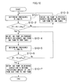
- Fig. 10 is a flowchart diagram showing a method of controlling the ink volume in the ink chamber 28 before an operation which consumes a large amount of ink (for instance, image formation or maintenance).
- step S10-1 the pressure P 1 inside the ink chamber 28 is determined by the ink chamber pressure gauge 18, and the pressure P 2 in the gas chamber 29 is determined by the gas chamber pressure gauge 19 (step S10-1).
- the liquid storage amount judgment device 21 determines the-pressure differential (P 1 - P 2 ) on the basis of the determination data for the pressure P 1 in the ink chamber 28 and the determination data for the pressure P 2 in the gas chamber 29. Then, in respect of the determined pressure differential (P 1 - P 2 ), it is judged whether or not the condition (P 1 - P 2 ) ⁇ P max is satisfied (step S10-2).
- the pressure P 1 in the ink chamber 28 is determined by the ink chamber pressure gauge 18, and the pressure P 2 in the gas chamber 29 is determined by the gas chamber pressure gauge 19 (step S10-5).
- the liquid storage amount judgment device 21 determines the pressure differential (P 1 - P 2 ) on the basis of the determination data for the pressure P 1 in the ink chamber 28 and the determination data for the pressure P 2 in the gas chamber 29. Then, in respect of the determined pressure differential (P 1 - P 2 ), it is judged whether or not the condition (P 1 - P 2 ) ⁇ P max is satisfied (step S10-6).
- step S10-7 corresponds to the step shown as (c) in Fig. 9 .
- Fig. 11 is a flowchart of a method of judging the state of deterioration of the flexible film 27. As shown in Fig. 11 , when the flowchart is started, firstly, the pressure P 1 in the ink chamber 28 is determined by the ink chamber pressure gauge 18, and the pressure P 2 in the gas chamber 29 is determined by the gas chamber pressure gauge 19 (step S11-1).
- the liquid storage amount judgment device 21 determines the pressure differential (P 1 - P 2 ) on the basis of the determination data for the pressure P 1 in the ink chamber 28 and the determination data for the pressure P 2 in the gas chamber 29. Then, in respect of the determined pressure differential (P 1 - P 2 ), it is judged whether or not the condition (P 1 - P 2 ) ⁇ P min is satisfied (step S11-2).
- step S11-3 if the condition (P 1 - P 2 ) ⁇ P min is not satisfied, then the ink pump 16 is driven in the reverse direction, ink is conveyed from the ink chamber 28 of the sub tank 13 to the ink tank 14, and this operation is repeated until the condition (P 1 - P 2 ) ⁇ P min is satisfied (step S11-3).
- the pressure P 1 in the ink chamber 28 is determined by the ink chamber pressure gauge 18, and the pressure P 2 in the gas chamber 29 is determined by the gas chamber pressure gauge 19 (step S11-5).
- the liquid storage amount judgment device 21 determines the pressure differential (P 1 - P 2 ) on the basis of the determination data for the pressure P 1 in the ink chamber 28 and the determination data for the pressure P 2 in the gas chamber 29. Then, in respect of the determined pressure differential (P 1 - P 2 ), it is judged whether or not the condition (P 1 - P 2 ) ⁇ P min is satisfied (step S11-6). The sequence is repeated until the condition (P 1 - P 2 ) ⁇ P min is satisfied.
- the pressure P 1 in the ink chamber 28 is determined by the ink chamber pressure gauge 18, and the pressure P 2 in the gas chamber 29 is determined by the gas chamber pressure gauge 19 (step S11-8).
- the liquid storage amount judgment device 21 determines the-pressure differential (P 1 - P 2 ) on the basis of the determination data for the pressure P 1 in the ink chamber 28 and the determination data for the pressure P 2 in the gas chamber 29. Then, in respect of the determined pressure differential (P 1 - P 2 ), it is judged whether or not the condition (P 1 - P 2 ) ⁇ P max is satisfied (step S11-9). The sequence is repeated until the condition (P 1 - P 2 ) ⁇ P max is satisfied.
- step S11-10 If, as a result, the condition (P 1 - P 2 ) ⁇ P max is satisfied, then the timer is stopped, and the time measurement is halted (step S11-10).
- step S11-11 the driving of the ink pump 16 is halted.
- the sequence of the steps S11-4 to S11-11 (the region indicated by “II” in Fig. 11 ) can be represented by "II” in the graph relating to the pressure differential (P 1 - P 2 ) and the ink volume in the ink chamber 28 shown in Fig. 12 .
- the measured time t of the timer is recorded in a memory (not illustrated) formed with the flexible film deterioration judgment device 24 (step S11-12).
- step S11-13 the ink pump 16 is driven in reverse, and a prescribed amount of ink is returned from the ink chamber 28 of the sub tank 13 to the ink tank 14 (step S11-13).
- the sequence of the step S11-13 (the region indicated by "III” in Fig. 11 ) can be represented by "III” in the graph relating the pressure differential (P 1 - P 2 ) and the ink volume in the ink chamber 28 shown in Fig. 12 .
- step S11-14 it is judged whether or not the measured time t is equal to or greater than a prescribed value T L by the flexible film deterioration judgment device 24 (step S11-14).
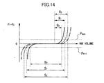
- the ink replenishment amount corresponding to II in Fig. 12 changes with the state of deterioration of the flexible film 27. Therefore, if the ink replenishment amount provided by the ink pump 16 per unit time is uniform, then the time (measured time t) required in order to supply the ink replenishment amount corresponding to II in Fig. 12 changes with the state of deterioration of the flexible film 27.
- the ink replenishment amount provided by the ink pump 16 per unit time is uniform, then the time (measured time t) required in order to supply the ink replenishment amount corresponding to II in Fig. 12 changes with the state of deterioration of the flexible film 27.
- the ink replenishment amount S 1 in a case where the flexible film 27 is in an advanced state of deterioration is greater than the ink replenishment amount So in a case where the state of deterioration of the flexible film 27 is not very advanced, and the measured time t in a case where the flexible film 27 is in an advanced state of deterioration is longer.
- the state of deterioration of the flexible film 27 is judged on the basis of the measured time t.
- the warning device 26 issues a warning that the replacement timing has been reached (step S11-15), whereupon the procedure ends.
- the measured time t is less than the prescribed value T L , then it is judged that the lifespan of the flexible film 27 has not yet been reached (step S11-16), and the procedure then ends.
- the prescribed value T L is the measured time t when the film is in a state of having 5% to 20% extension
- the flexible film 27 is an elastic membrane, then it is the measured time t when the tensile strength has fallen by 5% to 50%.
- the state of deterioration of the flexible film 27 is judged on the basis of the measured time t.
- the prescribed amount is changed as indicated by R 0 , R 1 , R 2 in Fig. 14 . More specifically, desirably, the prescribed amount increases as the deterioration of the flexible film 27 advances, and thereby the load applied to the flexible film 27 is reduced. Consequently, it is possible to lessen the load on the flexible film 27, and to increase the lifespan of the film. Furthermore, it is also possible to achieve a uniform remaining amount of ink in the ink chamber 28.
- the upper limit value P max and the lower limit value P min of the pressure differential (P 1 - P 2 ) at which the ink empty status or ink full status are determined may be reduced (changed so as to approach zero). Consequently, it is possible to lessen the load on the flexible film 27, and to increase the lifespan of the film.
- the state of deterioration of the flexible film 27 is judged as shown in Fig. 11 , when the image forming apparatus comprising the liquid ejection apparatus is started up and during maintenance.
- the liquid ejection apparatus comprises: a sub tank 13 having an ink chamber 28 which stores ink, a gas chamber 29 which fills with gas, and a flexible film 27 which divides the ink chamber 28 and the gas chamber 29; an ink tank 14 which stores ink and which is connected to the ink chamber 28; an ink pump 16 which conveys ink between the ink chamber 28 and the ink tank 14; a recording head 12 which is connected to the ink chamber 28; a controller 22 which controls the back pressure of the ink inside the recording head 12 by controlling the pressure in the gas chamber 29; an ink chamber pressure gauge 18 which determines the pressure P 1 of the ink chamber 28; a gas chamber pressure gauge 19 which determines the pressure P 2 of the gas chamber 29; and a liquid storage amount judgment device 21 which judges whether or not the amount of ink stored in the ink chamber 28 is within a tolerable range in which the back pressure in the recording head 12 can be controlled, on the basis of the pressure differential (P 1 - P 2 ), which is the difference between the pressure P
- the liquid storage amount judgment device 21 determines the range of the pressure differential (P 1 - P 2 ) in which the flexible film 27 can bend freely (the range of P min to P max ), and when this pressure differential has exceeded the limit values (P min , P max ) of the range (P min to P max ), it can determine that the amount of ink stored in the ink chamber 28 has reached a limit value ("ink empty” or "ink full") of the tolerable range in which the back pressure can be controlled.
- the controller 22 carries out replenishment supply for conveying ink from the ink tank 14 to the ink chamber 28 by means of the ink pump 16, and if it is judged by the liquid storage amount judgment device 21 that the ink storage amount in the ink chamber 28 has reached the upper limit value of the tolerable range in which the back pressure can be controlled, then the replenishment supply is halted, and by controlling the ink pump 16 in such a manner that a return supply is carried out for conveying ink from the ink chamber 28 to the ink tank 14, the load applied to the flexible film 27 is alleviated, and therefore it is possible to increase the lifespan of the flexible film 27, while achieving stable control of the back pressure.
- the controller 22 is able to provide a stable supply of ink from the ink tank 14 to the ink chamber 28, by controlling the speed during the replenishment supply to a uniform speed. Furthermore, by controlling the speed so as to change periodically, it is possible to apply a periodic variation to the flexible film 27 and therefore any bubbles or foreign material adhering thereto becomes more liable to be detached.
- the measured time t is determined, the measured time t being the time required for the ink storage amount in the ink chamber 28 to reach the upper limit value from the lower limit value of the tolerable range in which the back pressure can be controlled, by carrying out replenishment supply; and by providing a flexible film deterioration judgment device 24 which judges the state of deterioration of the flexible film 27 on the basis of the measured time t thus determined, then it is possible to determine the deterioration of the flexible film 27.
- the flexible film deterioration judgment device 24 judges that the flexible film 27 has reached an unusable state due to its deterioration, and therefore is able to determine the lifespan of the flexible film 27.
- warning device 26 which issues a warning that the replacement timing of the flexible film 27 has been reached, when it is judged by the flexible film deterioration judgment device 24 that the flexible film 27 is in an unusable state due to its deterioration.
- the controller 22 controls the prescribed amount of the ink (R 0 , R 1 , R 2 ) in the return supply in accordance with the measured time t, and hence the load applied to the flexible film 27 is reduced, the lifespan can be increased, and the amount of ink in the ink chamber 28 can be kept to a uniform amount.
- an inkjet recording apparatus is described as a concrete example of the application of an image forming apparatus comprising the liquid ejection apparatus according to an embodiment of the present invention.
- Fig. 15 is a general schematic drawing of an inkjet recording apparatus.
- the inkjet recording apparatus 110 comprises the liquid ejection apparatus 11 according to an embodiment of the present invention.
- Fig. 15 depicts, as parts of the liquid ejection apparatus 11 according to an embodiment of the present invention: a plurality of recording heads 12K, 12C, 12M, 12Y which are provided in accordance with the respective inks of the colors black (K), cyan (C), magenta (M), yellow (Y); a plurality of sub tanks 13K, 13C, 13M, 13Y provided to correspond to the respective recording heads; and an ink tank 14 which stores ink to be supplied to the respective sub tanks.
- the recording heads 12K, 12C, 12M, 12Y and the sub tanks 13K, 13C, 13M, 13Y are collectively termed the "printing unit 112".
- the inkjet recording apparatus 110 comprises: a paper supply unit 118 which supplies recording paper 116, which is one example of a recording medium; a decurling unit 120 which removes curl from the recording paper 116; a belt conveyance unit 122 which conveys the recording paper 116 while keeping the recording paper 116 flat; a print determination unit 124 which reads in the print results from the printing unit 112; and a paper output unit 126 which outputs the recording paper on which recording has been performed (printed object), to the exterior.
- a paper supply unit 118 which supplies recording paper 116, which is one example of a recording medium
- a decurling unit 120 which removes curl from the recording paper 116
- a belt conveyance unit 122 which conveys the recording paper 116 while keeping the recording paper 116 flat
- a print determination unit 124 which reads in the print results from the printing unit 112
- a paper output unit 126 which outputs the recording paper on which recording has been performed (printed object), to the exterior.
- the ink tank 14 stores inks of the colors corresponding to the respective sub tanks 13K, 13C, 13M and 13Y, and the respective tanks are connected to the sub tanks 13K, 13C, 13M and 13Y, via prescribed flow channels.
- the ink tank 14 also comprises a warning device (for example, a display device or an alarm sound generator) for warning when the remaining amount of any ink is low, and has a mechanism for preventing loading errors between different colors.
- a magazine for rolled paper (continuous paper) is shown as an example of the paper supply unit 118; however, a plurality of magazines with paper differences such as paper width and quality may be jointly provided. Moreover, papers may be supplied with cassettes that contain cut papers loaded in layers and that are used jointly or in lieu of the magazine for rolled paper.
- the recording paper 116 delivered from the paper supply unit 118 retains curl due to having been loaded in the magazine.
- heat is applied to the recording paper 116 in the decurling unit 120 by a heating drum 130 in the direction opposite from the curl direction in the magazine.
- a cutter (first cutter) 128 is provided as shown in Fig. 15 , and the continuous paper is cut into a desired size by the cutter 128.
- the cutter 128 is not required.
- the decurled and cut recording paper 116 is delivered to the belt conveyance unit 122.
- the belt conveyance unit 122 has a configuration in which an endless belt 133 is set around rollers 131 and 132 so that the portion of the endless belt 133 facing at least the nozzle face of the printing unit 112 and the sensor face of the print determination unit 124 forms a horizontal plane (flat plane).
- the belt 133 has a width that is greater than the width of the recording paper 116, and a plurality of suction apertures (not shown) are formed on the belt surface.
- a suction chamber 134 is disposed in a position facing the sensor surface of the print determination unit 124 and the nozzle surface of the printing unit 112 on the interior side of the belt 133, which is set around the rollers 131 and 132, as shown in Fig. 15 .
- the suction chamber 134 provides suction with a fan 135 to generate a negative pressure, and the recording paper 116 is held on the belt 133 by suction. It is also possible to use an electrostatic attraction method, instead of a suction-based attraction method.
- the belt 133 is driven in the clockwise direction in Fig. 15 by the motive force of a motor (reference numeral 188 shown in Fig. 20 ) being transmitted to at least one of the rollers 131 and 132, which the belt 133 is set around, and the recording paper 116 held on the belt 133 is conveyed from left to right in Fig. 16 .
- a motor reference numeral 188 shown in Fig. 20
- a belt-cleaning unit 136 is disposed in a predetermined position (a suitable position outside the printing area) on the exterior side of the belt 133.
- a heating fan 140 is disposed on the upstream side of the printing unit 112 in the conveyance pathway formed by the belt conveyance unit 122.
- the heating fan 140 blows heated air onto the recording paper 116 to heat the recording paper 116 immediately before printing so that the ink deposited on the recording paper 116 dries more easily.
- the recording heads 12K, 12C, 12M and 12Y of the printing unit 112 are full line recording heads having a length corresponding to the maximum width of the recording paper 116 used with the inkjet recording apparatus 110, and comprising a plurality of nozzles for ejecting ink arranged on a nozzle face through a length exceeding at least one edge of the maximum-size recording medium (namely, the full width of the printable range).
- the recording heads 12K, 12C, 12M and 12Y are arranged in color order (black (K), cyan (C), magenta (M), yellow (Y)) from the upstream side in the feed direction of the recording paper 116, and these respective recording heads 12K, 12C, 12M and 12Y are fixed extending in a direction substantially perpendicular to the conveyance direction of the recording paper 116.
- a color image can be formed on the recording paper 116 by ejecting inks of different colors from the recording heads 12K, 12C, 12M and 12Y, respectively, onto the recording paper 116 while the recording paper 116 is conveyed by the belt conveyance unit 122.
- ink colors and the number of colors are not limited to those.
- Light inks, dark inks or special color inks can be added as required.
- inkjet heads for ejecting light-colored inks such as light cyan and light magenta are added.
- sequence in which the heads of respective colors are arranged there are no particular restrictions of the sequence in which the heads of respective colors are arranged.
- the print determination unit 124 shown in Fig. 15 has an image sensor (line sensor or area sensor) for capturing an image of the ink-droplet deposition result of the printing unit 112, and functions as a device to check the ejection characteristics, such as blockages, landing position error, and the like, of the nozzles, on the basis of the image of ejected droplets read in by the image sensor.
- image sensor line sensor or area sensor
- a two-dimensional array CCD area sensor in which a plurality of photoreceptor elements (photoelectric transducers) are arranged in the light receiving surface is suitable for use as the print determination unit 124 of the present example.
- An area sensor has an imaging range which is capable of capturing an image of at least the full area of the ink ejection width (image recording width) of the respective recording heads 12K, 12C, 12M and 12Y
- a desirable composition is one in which the line sensor has rows of photoreceptor elements (rows of photoelectric transducing elements) with a width that is at least greater than the ink droplet ejection width (image recording width) of the recording heads 12K, 12C, 12M and 12Y.
- a test pattern or the target image printed by the recording heads 12K, 12C, 12M, and 12Y of the respective colors is read in by the print determination unit 124, and the ejection performed by each recording head is determined.
- the ejection determination includes detection of the ejection, measurement of the dot size, and measurement of the dot formation position.
- a post-drying unit 142 is disposed following the print determination unit 124.
- the post-drying unit 142 is a device to dry the printed image surface, and includes a heating fan, for example.
- a heating/pressurizing unit 144 is disposed following the post-drying unit 142.
- the heating/pressurizing unit 144 is a device to control the glossiness of the image surface, and the image surface is pressed with a pressure roller 145 having a predetermined uneven surface shape while the image surface is heated, and the uneven shape is transferred to the image surface.
- the printed matter generated in this manner is outputted from the paper output unit 126.
- the target print i.e., the result of printing the target image
- the test print are desirably outputted separately.
- a sorting device (not shown) is provided for switching the outputting pathways in order to sort the printed matter with the target print and the printed matter with the test print, and to send them to paper output units 126A and 126B, respectively.
- the test print portion is cut and separated by a cutter (second cutter) 148.
- the recording heads 12K, 12C, 12M and 12Y of the respective ink colors have the same structure, and a reference numeral 150 is designated to any of the recording heads.
- Fig. 17A is a perspective plan view showing an example of the configuration of the recording head 150
- Fig. 17B is an enlarged view of a portion thereof
- Fig. 17C is a perspective plan view showing another example of the configuration of the recording head
- Fig. 18 is a cross-sectional view taken along the line 18-18 in Figs. 17A and 17B , showing the inner structure of a droplet ejection element (an ink chamber unit for one nozzle 151).
- the recording head 150 should be minimized in order to maximize the density of the dots printed on the surface of the recording paper 116.
- the recording head 150 has a structure in which a plurality of ink chamber units 153, each comprising a nozzle 151 forming an ink ejection port, a pressure chamber 152 corresponding to the nozzle 151, and the like, are disposed two-dimensionally in the form of a staggered matrix, and hence the effective nozzle interval (the projected nozzle pitch) as projected in the lengthwise direction of the recording head (the direction perpendicular to the paper conveyance direction) is reduced and high nozzle density is achieved.
- the mode of forming one or more nozzle rows through a length corresponding to the entire width of the recording paper 116 in a direction substantially perpendicular to the conveyance direction of the recording paper 116 is not limited to the example described above.
- a line head having nozzle rows of a length corresponding to the entire width of the recording paper 116 can be formed by arranging and combining, in a staggered matrix, short head modules 150' having a plurality of nozzles 151 arrayed in a two-dimensional fashion.
- the planar shape of the pressure chamber 152 provided for each nozzle 151 is substantially a square, and an outlet to the nozzle 151 is disposed at one corner on a diagonal line of the square and a supply port 154 that is an inlet of supplied ink is disposed at the other corner on this diagonal line.
- the shape of the pressure chamber 152 is not limited to that of the present example and various modes are possible in which the planar shape is a quadrilateral shape (diamond shape, rectangular shape, or the like), a pentagonal shape, a hexagonal shape, or other polygonal shape, or a circular shape, elliptical shape, or the like.
- the ink chamber unit 153 is constituted by a supply port 154, a pressure chamber 152, a nozzle 151, a pressurization plate 156, an individual electrode 157, an actuator 158, and the like.
- the respective pressure chambers 152 of the plurality of ink chamber units 153 are connected to a common flow channel 155. As shown in Fig. 18 , each pressure chamber 152 is connected to the common channel 155 through the supply port 154.
- the common channel 155 is connected to an ink tank, which is a base tank that supplies ink, and the ink supplied from the ink tank is delivered through the common flow channel 155 to the pressure chambers 152.
- Actuators 158 each provided with an individual electrode 157 are bonded to a pressure plate 156 (a diaphragm that also serves as a common electrode) which forms the surface of one portion (in Fig. 18 , the ceiling) of the pressure chambers 152.
- a drive voltage is applied to the individual electrode 157 and the common electrode, the actuator 158 is deformed, the volume of the pressure chamber 152 is thereby changed, and the pressure in the pressure chamber 152 is thereby changed, so that the ink inside the pressure chamber 152 is ejected through the nozzle 151.
- the actuators 158 it is possible to adopt a piezoelectric element using a piezoelectric body, such as lead zirconate titanate, barium titanate, or the like.
- the high-density nozzle head according to this example is achieved by arranging a plurality of ink chamber units 153 having the above-described structure in a lattice fashion based on a fixed arrangement pattern, in a row direction which coincides with the main scanning direction, and a column direction which is inclined at a fixed angle of ⁇ with respect to the main scanning direction, rather than being perpendicular to the main scanning direction.
- the pitch P of the nozzles projected so as to align in the main scanning direction is d ⁇ cos ⁇ , and hence the nozzles 151 can be regarded to be equivalent to those arranged linearly at a fixed pitch P along the main scanning direction.
- Such configuration results in a nozzle structure in which the nozzle row projected in the main scanning direction has a high nozzle density of up to 2,400 nozzles per inch.
- the "main scanning" is defined as printing one line (a line formed of a row of dots, or a line formed of a plurality of rows of dots) in the width direction of the recording paper (the direction perpendicular to the conveyance direction of the recording paper) by driving the nozzles in one of the following ways: (1) simultaneously driving all the nozzles; (2) sequentially driving the nozzles from one side toward the other; and (3) dividing the nozzles into blocks and sequentially driving the nozzles from one side toward the other in each of the blocks.
- the main scanning according to the above-described (3) method is preferred. More specifically, the nozzles 151-11, 151-12, 151-13, 151-14, 151-15 and 1-51-16 are treated as a block (additionally; the nozzles 151-21, ..., 151-26 are treated as another block; the nozzles 151-31, ..., 151-36 are treated as another block; ...); and one line is printed in the width direction of the recording paper 116 by sequentially driving the nozzles 151-11, 151-12, ..., 151-16 in accordance with the conveyance velocity of the recording paper 116.
- sub-scanning is defined as to repeatedly perform printing of one line (a line formed of a row of dots, or a line formed of a plurality of rows of dots) formed by the main scanning, while moving the full-line head and the recording paper relatively to each other.
- the direction indicated by one line (or the lengthwise direction of a band-shaped region) recorded by the main scanning as described above is called the "main scanning direction", and the direction in which sub-scanning is performed, is called the "sub-scanning direction”.
- the conveyance direction of the recording paper 116 is called the sub-scanning direction and the direction perpendicular to same is called the main scanning direction.
- the arrangement of the nozzles is not limited to that of the example illustrated.
- a method is employed in the present embodiment where an ink droplet is ejected by means of the deformation of the actuator 158, which is typically a piezoelectric element; however, in implementing embodiments of the present invention, the method used for discharging ink is not limited in particular, and instead of the piezo jet method, it is also possible to apply various types of methods, such as a thermal jet method where the ink is heated and bubbles are caused to form therein by means of a heat generating body such as a heater, ink droplets being ejected by means of the pressure applied by these bubbles.
- Fig. 20 is a block diagram showing a system composition of the inkjet recording apparatus 110.
- the inkjet recording apparatus 110 comprises a communications interface 170, a system controller 172, an image memory 174, a ROM 175, a motor driver 176, a heater driver 178, a print controller 180, an image buffer memory 182, a head driver 184, and the like.
- the communications interface 170 is an interface unit (image input unit) which functions as an image input device for receiving image data transmitted from the host computer 186.
- a serial interface such as USB (Universal Serial Bus), IEEE1394, Ethernet (registered trademark), wireless network, or a parallel interface such as a Centronics interface may be used as the communications interface 170.
- a buffer memory (not shown) may be mounted in this portion in order to increase the communication speed.
- the image data sent from the host computer 186 is received by the inkjet recording apparatus 110 through the communications interface 170, and is temporarily stored in the image memory 174.
- the image memory 174 is a storage device for storing images inputted through the communications interface 170, and data is written and read to and from the image memory 174 through the system controller 172.
- the image memory 174 is not limited to a memory composed of semiconductor elements, and a hard disk drive or another magnetic medium may be used.
- the system controller 172 is constituted by a central processing unit (CPU) and peripheral circuits thereof, and the like, and it functions as a control device for controlling the whole of the inkjet recording apparatus 110 in accordance with prescribed programs, as well as a calculation device for performing various calculations. More specifically, the system controller 172 controls the various sections, such as the communications interface 170, image memory 174, motor driver 176, heater driver 178, and the like, as well as controlling communications with the host computer 186 and writing and reading to and from the image memory 174 and ROM 175, and it also generates control signals for controlling the motor 188 and heater 189 of the conveyance system.
- CPU central processing unit
- system controller 172 internally comprises the liquid storage amount judgment device 21, the controller 22 and the flexible film deterioration judgment device 24, and it controls the drive device 23 and the warning device 26.
- the ROM 175 may be a non-writeable storage device, or it may be a rewriteable storage device, such as an EEPROM.
- the image memory 174 is used as a temporary storage region for the image data, and it is also used as a program development region and a calculation work region for the CPU.
- the motor driver (drive circuit) 176 drives the motor 188 of the conveyance system in accordance with commands from the system controller 172.
- the heater driver (drive circuit) 178 drives the heater 189 of the post-drying unit 142 and the like in accordance with commands from the system controller 172.
- the print controller 180 is a control unit which functions as a signal processing device for performing various treatment processes, corrections, and the like, in accordance with the control implemented by the system controller 172, in order to generate a signal for controlling droplet ejection from the image data (multiple-value input image data) in the image memory 174, as well as functioning as a drive control device which controls the ejection driving of the recording head 150 by supplying the ink ejection data thus generated to the head driver 184.
- the image buffer memory 182 is provided in the print controller 180, and image data, parameters, and other data are temporarily stored in the image buffer memory 182 when image data is processed in the print controller 180.
- Fig. 20 shows a mode in which the image buffer memory 182 is attached to the print controller 180; however, the image memory 174 may also serve as the image buffer memory 182. Also possible is a mode in which the print controller 180 and the system controller 172 are integrated to form a single processor.
- image data to be printed (original image data) is input from an external source via the communications interface 170, and is accumulated in the image memory 174.
- image memory 174 At this stage, multiple-value RGB image data is stored in the image memory 174, for example.
- the print controller 180 performs processing for converting the input RGB image data into dot data for the four colors of K, C, M and Y.
- the dot data generated by the print controller 180 in this way is stored in the image buffer memory 182.
- This dot data of the respective colors is converted into CMYK droplet ejection data for ejecting ink from the nozzles of the recording heads 150, thereby establishing the ink ejection data to be printed.
- the head driver 184 outputs drive signals for driving the actuators 158 corresponding to the nozzles 151 of the recording heads 150 in accordance with the print contents, on the basis of the ink ejection data and the drive waveform signals supplied by the print controller 180.
- a feedback control system for maintaining constant drive conditions in the head may be included in the head driver 184.
- the recording volume and the ejection timing of the ink droplets from the respective nozzles are controlled via the head driver 184, on the basis of the ink ejection data and the drive signal waveform generated by implementing required signal processing in the print controller 180.
- desired dot sizes and dot positions can be achieved.
- the print determination unit 124 is a block that includes the image sensor as described above with reference to Fig. 15 , reads the image printed on the recording paper 116, determines the print conditions (presence of the ejection, variation in the dot formation, optical density, and the like) by performing required signal processing, or the like, and provides the determination results of the print conditions to the print controller 180.
- the print controller 180 implements various corrections with respect to the recording head 150, on the basis of the information obtained from the print determination unit 124, according to requirements, and it implements control for carrying out cleaning operations (nozzle restoring operations), such as preliminary ejection, suctioning, or wiping, as and when necessary.
- cleaning operations nozzle restoring operations
- Liquid droplet ejection apparatuses, image forming apparatuses and liquid storage amount judgment methods according to embodiments of the present invention have been described in detail above, but the present invention is not limited to the aforementioned examples, and it is of course possible for improvements or modifications of various kinds to be implemented, within a range which does not deviate from the essence of the present invention.
Applications Claiming Priority (1)
| Application Number | Priority Date | Filing Date | Title |
|---|---|---|---|
| JP2007193714A JP5248816B2 (ja) | 2007-07-25 | 2007-07-25 | 液体吐出装置および画像形成装置 |
Publications (3)
| Publication Number | Publication Date |
|---|---|
| EP2018970A2 true EP2018970A2 (de) | 2009-01-28 |
| EP2018970A3 EP2018970A3 (de) | 2010-07-28 |
| EP2018970B1 EP2018970B1 (de) | 2011-09-21 |
Family
ID=39884943
Family Applications (1)
| Application Number | Title | Priority Date | Filing Date |
|---|---|---|---|
| EP08013178A Expired - Fee Related EP2018970B1 (de) | 2007-07-25 | 2008-07-22 | Flüssigkeitsausgabevorrichtung, Bildgebungsvorrichtung und Mengenbeurteilungsverfahren für einen Flüssigkeitsspeicher |
Country Status (4)
| Country | Link |
|---|---|
| US (1) | US8235482B2 (de) |
| EP (1) | EP2018970B1 (de) |
| JP (1) | JP5248816B2 (de) |
| CN (1) | CN101352969B (de) |
Cited By (6)
| Publication number | Priority date | Publication date | Assignee | Title |
|---|---|---|---|---|
| ITMI20091564A1 (it) * | 2009-09-11 | 2011-03-12 | Reggiani Macchine Spa | Disposizione di alimentazione per una testa di stampa a getto d'inchiostro e relativa macchina di stampa per tessuti. |
| EP2923841A3 (de) * | 2014-03-26 | 2016-08-24 | Canon Finetech Inc. | Flüssigkeitsversorgungsvorrichtung und flüssigkeitsausstossvorrichtung |
| US9840083B2 (en) | 2015-08-13 | 2017-12-12 | Heidelberger Druckmaschinen Ag | Method for damping pressure peaks in a line for ink of an inkjet printer |
| EP3415240A1 (de) * | 2017-06-15 | 2018-12-19 | The Boeing Company | Tintenstrahldrucksystem mit dynamisch kontrolliertem tintenbehälter |
| DE102018110048A1 (de) * | 2018-04-26 | 2019-10-31 | Océ Holding B.V. | Verfahren zum Überprüfen der Funktionsfähigkeit eines hydraulischen Dämpfers in einem Tintensystem und Tintensystem |
| EP3708374A1 (de) * | 2019-03-12 | 2020-09-16 | Ricoh Company, Ltd. | Flüssigkeitsbehälter mit flexibler membran für einen durchflussdruckkopf |
Families Citing this family (25)
| Publication number | Priority date | Publication date | Assignee | Title |
|---|---|---|---|---|
| JP4784675B2 (ja) * | 2009-03-30 | 2011-10-05 | ブラザー工業株式会社 | 記録装置 |
| JP5344298B2 (ja) * | 2009-04-17 | 2013-11-20 | 株式会社リコー | 画像形成装置 |
| JP5537988B2 (ja) * | 2010-02-23 | 2014-07-02 | 富士フイルム株式会社 | 液体供給系の異常判定装置及び異常判定方法 |
| JP5438622B2 (ja) * | 2010-07-30 | 2014-03-12 | 富士フイルム株式会社 | 液体供給装置及び液体吐出装置並びに圧力制御方法 |
| JP5703246B2 (ja) * | 2012-02-29 | 2015-04-15 | 富士フイルム株式会社 | 液体吐出装置及び液体供給装置 |
| CN102765257B (zh) * | 2012-08-10 | 2015-02-25 | 李支斌 | 打印机墨水管路恒压缓冲分配器 |
| JP2015066842A (ja) * | 2013-09-30 | 2015-04-13 | 富士フイルム株式会社 | 圧力緩衝装置、液体流通装置、画像記録装置、及び液体流通装置の状態検出方法 |
| US9994036B2 (en) | 2014-02-04 | 2018-06-12 | Hewlett-Packard Development Company, L.P. | Sensor assemblies to identify ink levels |
| JP6346513B2 (ja) | 2014-07-11 | 2018-06-20 | キヤノン株式会社 | 液体吐出装置、インプリント装置および物品製造方法 |
| JP6530653B2 (ja) * | 2014-07-25 | 2019-06-12 | キヤノン株式会社 | 液体吐出装置、インプリント装置および物品製造方法 |
| CN104296831A (zh) * | 2014-11-05 | 2015-01-21 | 成都思达高科软件有限公司 | 一种改进的液位变送器的检测装置 |
| TWI649212B (zh) * | 2015-04-03 | 2019-02-01 | 佳能股份有限公司 | 液體排放設備、壓印設備及部件製造方法 |
| JP6579800B2 (ja) * | 2015-05-25 | 2019-09-25 | キヤノン株式会社 | インクジェット記録装置 |
| CN110869215B (zh) | 2017-07-12 | 2021-09-03 | 惠普发展公司,有限责任合伙企业 | 确定喷墨打印机缺乏液体状态的方法和喷墨打印装置 |
| US10421283B2 (en) | 2017-09-06 | 2019-09-24 | Canon Kabushiki Kaisha | Ejection material receiving unit, ejection material ejecting apparatus, and manufacturing method of flexible member |
| KR102312743B1 (ko) * | 2017-11-30 | 2021-10-18 | 캐논 가부시끼가이샤 | 토출재 토출 장치 및 임프린트 장치 |
| JP6978338B2 (ja) * | 2018-02-15 | 2021-12-08 | 東芝テック株式会社 | 液体循環装置、及び液体吐出装置 |
| JP7242810B2 (ja) * | 2018-02-15 | 2023-03-20 | 東芝テック株式会社 | 液体循環装置、及び液体吐出装置 |
| TWI690801B (zh) * | 2018-12-28 | 2020-04-11 | 新唐科技股份有限公司 | 偵測電路及其方法 |
| JP7346836B2 (ja) * | 2019-02-06 | 2023-09-20 | 京セラドキュメントソリューションズ株式会社 | 画像形成装置 |
| JP7190364B2 (ja) * | 2019-02-20 | 2022-12-15 | ローランドディー.ジー.株式会社 | インクジェットプリンタおよびコンピュータプログラム |
| DE102020115729A1 (de) | 2019-07-11 | 2021-01-14 | Heidelberger Druckmaschinen Aktiengesellschaft | Vorrichtung zur Versorgung eines Tinten-Druckkopfs einer Tinten-Druckmaschine mit flüssiger Tinte |
| WO2021046023A1 (en) * | 2019-09-06 | 2021-03-11 | Dow Global Technologies Llc | Multilayer panel member |
| CN110823315B (zh) * | 2019-12-12 | 2020-06-09 | 深圳市腾盛精密装备股份有限公司 | 一种非接触式高精度液位检测系统及其检测方法 |
| CN114103470B (zh) * | 2021-11-10 | 2023-01-10 | Tcl华星光电技术有限公司 | 液体循环系统及循环方法 |
Citations (2)
| Publication number | Priority date | Publication date | Assignee | Title |
|---|---|---|---|---|
| JPS59104947A (ja) | 1982-12-08 | 1984-06-18 | Konishiroku Photo Ind Co Ltd | インクジエツト記録装置 |
| JP2003300331A (ja) | 2002-04-10 | 2003-10-21 | Matsushita Electric Ind Co Ltd | インクジェット記録装置 |
Family Cites Families (21)
| Publication number | Priority date | Publication date | Assignee | Title |
|---|---|---|---|---|
| US4604633A (en) * | 1982-12-08 | 1986-08-05 | Konishiroku Photo Industry Co., Ltd | Ink-jet recording apparatus |
| JPH01263053A (ja) * | 1988-04-15 | 1989-10-19 | Canon Inc | インク残量検出装置 |
| WO1995031335A1 (fr) * | 1994-05-17 | 1995-11-23 | Seiko Epson Corporation | Enregistreur a jet d'encre et procede de nettoyage de la tete d'enregistrement |
| JP3768725B2 (ja) * | 1998-06-15 | 2006-04-19 | キヤノン株式会社 | インクジェット記録装置 |
| DE19906826B4 (de) * | 1998-09-01 | 2005-01-27 | Hewlett-Packard Co. (N.D.Ges.D.Staates Delaware), Palo Alto | Auf Druck basierender Tintenpegeldetektor und Verfahren zum Erfassen eines Tintenpegels |
| JP2001001546A (ja) * | 1999-06-24 | 2001-01-09 | Canon Inc | 液体供給システム及び該システムに用いられる液体供給容器 |
| WO2001032424A2 (fr) * | 1999-11-05 | 2001-05-10 | Seiko Epson Corporation | Dispositif d'impression de type jet d'encre, procede d'alimentation en encre de reservoir secondaire et procede d'evaluation de quantite d'encre fournie a ce reservoir par le meme dispositif |
| EP1097814B1 (de) * | 1999-11-05 | 2004-06-23 | Seiko Epson Corporation | Tintenstrahlaufzeichnungsvorrichtung |
| JP2001212974A (ja) * | 2000-02-01 | 2001-08-07 | Seiko Epson Corp | インクジェット式記録装置および同装置におけるサブタンクへのインク補給方法 |
| ATE326347T1 (de) * | 2000-01-21 | 2006-06-15 | Seiko Epson Corp | Tintenpatrone und tintenstrahldruckvorrichtung mit einer derartigen tintenpatrone |
| EP2105308B1 (de) * | 2000-01-21 | 2012-04-25 | Seiko Epson Corporation | Tintenpatrone für Aufzeichnungsgerät und Tintenstrahlaufzeichnungsgerät |
| US6644794B1 (en) * | 2000-10-27 | 2003-11-11 | Hewlett-Packard Development Company, L.P. | Collapsible ink reservoir with a collapse resisting insert |
| JP3586222B2 (ja) * | 2001-06-18 | 2004-11-10 | キヤノン株式会社 | インク貯留容器および該容器を用いるインクジェットプリント装置 |
| JP2003266734A (ja) * | 2002-03-14 | 2003-09-24 | Canon Inc | インクジェット記録装置およびインク供給方法 |
| US6886929B2 (en) * | 2002-10-25 | 2005-05-03 | Hewlett-Packard Development Company, L.P. | Techniques for improving pressure sensor shock robustness in fluid containment devices |
| JP4105135B2 (ja) * | 2004-08-30 | 2008-06-25 | シャープ株式会社 | インクジェットヘッド装置、インクジェット装置、及びインクジェットヘッド装置のインク供給方法 |
| JP4434032B2 (ja) * | 2005-02-16 | 2010-03-17 | セイコーエプソン株式会社 | 液滴吐出装置の制御方法、液滴吐出装置、電気光学装置の製造方法 |
| JP2007196588A (ja) * | 2006-01-27 | 2007-08-09 | Seiko Epson Corp | 液体噴射装置 |
| JP2008030219A (ja) * | 2006-07-26 | 2008-02-14 | Seiko Epson Corp | 液体噴射装置、液体収容体、及び液体収容体の液体残量判定方法 |
| JP4920446B2 (ja) * | 2007-02-16 | 2012-04-18 | 富士フイルム株式会社 | 圧力調整装置および画像形成装置並びに圧力調整方法および液体残量検出方法 |
| JP2008230137A (ja) * | 2007-03-22 | 2008-10-02 | Fujifilm Corp | 液体吐出ヘッドの背圧調整装置 |
-
2007
- 2007-07-25 JP JP2007193714A patent/JP5248816B2/ja not_active Expired - Fee Related
-
2008
- 2008-07-21 US US12/176,851 patent/US8235482B2/en active Active
- 2008-07-22 EP EP08013178A patent/EP2018970B1/de not_active Expired - Fee Related
- 2008-07-24 CN CN2008101300351A patent/CN101352969B/zh not_active Expired - Fee Related
Patent Citations (2)
| Publication number | Priority date | Publication date | Assignee | Title |
|---|---|---|---|---|
| JPS59104947A (ja) | 1982-12-08 | 1984-06-18 | Konishiroku Photo Ind Co Ltd | インクジエツト記録装置 |
| JP2003300331A (ja) | 2002-04-10 | 2003-10-21 | Matsushita Electric Ind Co Ltd | インクジェット記録装置 |
Cited By (8)
| Publication number | Priority date | Publication date | Assignee | Title |
|---|---|---|---|---|
| ITMI20091564A1 (it) * | 2009-09-11 | 2011-03-12 | Reggiani Macchine Spa | Disposizione di alimentazione per una testa di stampa a getto d'inchiostro e relativa macchina di stampa per tessuti. |
| EP2923841A3 (de) * | 2014-03-26 | 2016-08-24 | Canon Finetech Inc. | Flüssigkeitsversorgungsvorrichtung und flüssigkeitsausstossvorrichtung |
| US9475305B2 (en) | 2014-03-26 | 2016-10-25 | Canon Finetech Inc. | Liquid supply apparatus and liquid ejection apparatus with contactless detection of liquid remaining amount |
| US9840083B2 (en) | 2015-08-13 | 2017-12-12 | Heidelberger Druckmaschinen Ag | Method for damping pressure peaks in a line for ink of an inkjet printer |
| EP3415240A1 (de) * | 2017-06-15 | 2018-12-19 | The Boeing Company | Tintenstrahldrucksystem mit dynamisch kontrolliertem tintenbehälter |
| US10259234B2 (en) | 2017-06-15 | 2019-04-16 | The Boeing Company | Inkjet printing system having dynamically controlled ink reservoir |
| DE102018110048A1 (de) * | 2018-04-26 | 2019-10-31 | Océ Holding B.V. | Verfahren zum Überprüfen der Funktionsfähigkeit eines hydraulischen Dämpfers in einem Tintensystem und Tintensystem |
| EP3708374A1 (de) * | 2019-03-12 | 2020-09-16 | Ricoh Company, Ltd. | Flüssigkeitsbehälter mit flexibler membran für einen durchflussdruckkopf |
Also Published As
| Publication number | Publication date |
|---|---|
| EP2018970B1 (de) | 2011-09-21 |
| CN101352969B (zh) | 2011-10-19 |
| EP2018970A3 (de) | 2010-07-28 |
| CN101352969A (zh) | 2009-01-28 |
| US8235482B2 (en) | 2012-08-07 |
| JP5248816B2 (ja) | 2013-07-31 |
| US20090027435A1 (en) | 2009-01-29 |
| JP2009028963A (ja) | 2009-02-12 |
Similar Documents
| Publication | Publication Date | Title |
|---|---|---|
| EP2018970B1 (de) | Flüssigkeitsausgabevorrichtung, Bildgebungsvorrichtung und Mengenbeurteilungsverfahren für einen Flüssigkeitsspeicher | |
| US7448706B2 (en) | Image forming apparatus and method | |
| US7275801B2 (en) | Image forming apparatus | |
| US7802878B2 (en) | Liquid droplet ejection mechanism and image forming apparatus | |
| US8292401B2 (en) | Image recording apparatus and image recording method | |
| US7357472B2 (en) | Inkjet recording apparatus and method | |
| US7527363B2 (en) | Discharge head of image forming apparatus with piezoelectric body for generating and sensing pressure | |
| US7724395B2 (en) | Dot arrangement determination method, program and apparatus, threshold matrix creating method and program, and image forming apparatus | |
| US7537305B2 (en) | Image recording apparatus and image recording method | |
| US20100214347A1 (en) | Image recording apparatus, image processing apparatus, image processing method and computer-readable medium | |
| US7575306B2 (en) | Discharge head, method of manufacturing discharge head, and liquid discharge apparatus | |
| US8482822B2 (en) | Image recording apparatus, image processing apparatus, image processing method and computer-readable medium for selecting a subsidiary image processing device | |
| US20050195248A1 (en) | Discharge determination device and method | |
| US7669954B2 (en) | Liquid ejection apparatus and recording apparatus | |
| US7458654B2 (en) | Liquid ejection apparatus and ejection abnormality determination method | |
| US7591520B2 (en) | Ink jet printer and method for determining pulse width | |
| US7401896B2 (en) | Liquid droplet ejection head, liquid droplet ejection apparatus and image recording method | |
| US7645010B2 (en) | Ink ejection amount measurement method and ink ejection amount measurement system | |
| US9327497B2 (en) | Liquid discharge apparatus | |
| US7540595B2 (en) | Liquid ejection head | |
| US7296878B2 (en) | Liquid ejection head, liquid ejection apparatus and image forming apparatus | |
| JP7222268B2 (ja) | 画像記録装置 | |
| US20060044358A1 (en) | Ejection head and image forming apparatus | |
| US20050068379A1 (en) | Droplet discharge head and inkjet recording apparatus | |
| US7651192B2 (en) | Liquid droplet deposition method and liquid droplet deposition apparatus |
Legal Events
| Date | Code | Title | Description |
|---|---|---|---|
| PUAI | Public reference made under article 153(3) epc to a published international application that has entered the european phase |
Free format text: ORIGINAL CODE: 0009012 |
|
| AK | Designated contracting states |
Kind code of ref document: A2 Designated state(s): AT BE BG CH CY CZ DE DK EE ES FI FR GB GR HR HU IE IS IT LI LT LU LV MC MT NL NO PL PT RO SE SI SK TR |
|
| AX | Request for extension of the european patent |
Extension state: AL BA MK RS |
|
| PUAL | Search report despatched |
Free format text: ORIGINAL CODE: 0009013 |
|
| AK | Designated contracting states |
Kind code of ref document: A3 Designated state(s): AT BE BG CH CY CZ DE DK EE ES FI FR GB GR HR HU IE IS IT LI LT LU LV MC MT NL NO PL PT RO SE SI SK TR |
|
| AX | Request for extension of the european patent |
Extension state: AL BA MK RS |
|
| 17P | Request for examination filed |
Effective date: 20101125 |
|
| GRAP | Despatch of communication of intention to grant a patent |
Free format text: ORIGINAL CODE: EPIDOSNIGR1 |
|
| RIC1 | Information provided on ipc code assigned before grant |
Ipc: B41J 2/175 20060101AFI20110117BHEP |
|
| AKX | Designation fees paid |
Designated state(s): DE FR GB |
|
| GRAS | Grant fee paid |
Free format text: ORIGINAL CODE: EPIDOSNIGR3 |
|
| GRAA | (expected) grant |
Free format text: ORIGINAL CODE: 0009210 |
|
| AK | Designated contracting states |
Kind code of ref document: B1 Designated state(s): DE FR GB |
|
| REG | Reference to a national code |
Ref country code: GB Ref legal event code: FG4D |
|
| REG | Reference to a national code |
Ref country code: DE Ref legal event code: R096 Ref document number: 602008009921 Country of ref document: DE Effective date: 20111215 |
|
| PLBE | No opposition filed within time limit |
Free format text: ORIGINAL CODE: 0009261 |
|
| STAA | Information on the status of an ep patent application or granted ep patent |
Free format text: STATUS: NO OPPOSITION FILED WITHIN TIME LIMIT |
|
| 26N | No opposition filed |
Effective date: 20120622 |
|
| REG | Reference to a national code |
Ref country code: DE Ref legal event code: R097 Ref document number: 602008009921 Country of ref document: DE Effective date: 20120622 |
|
| REG | Reference to a national code |
Ref country code: FR Ref legal event code: PLFP Year of fee payment: 9 |
|
| REG | Reference to a national code |
Ref country code: FR Ref legal event code: PLFP Year of fee payment: 10 |
|
| REG | Reference to a national code |
Ref country code: DE Ref legal event code: R082 Ref document number: 602008009921 Country of ref document: DE Representative=s name: KLUNKER IP PATENTANWAELTE PARTG MBB, DE |
|
| REG | Reference to a national code |
Ref country code: FR Ref legal event code: PLFP Year of fee payment: 11 |
|
| PGFP | Annual fee paid to national office [announced via postgrant information from national office to epo] |
Ref country code: FR Payment date: 20180612 Year of fee payment: 11 |
|
| PGFP | Annual fee paid to national office [announced via postgrant information from national office to epo] |
Ref country code: DE Payment date: 20180710 Year of fee payment: 11 |
|
| PGFP | Annual fee paid to national office [announced via postgrant information from national office to epo] |
Ref country code: GB Payment date: 20180718 Year of fee payment: 11 |
|
| REG | Reference to a national code |
Ref country code: DE Ref legal event code: R119 Ref document number: 602008009921 Country of ref document: DE |
|
| GBPC | Gb: european patent ceased through non-payment of renewal fee |
Effective date: 20190722 |
|
| PG25 | Lapsed in a contracting state [announced via postgrant information from national office to epo] |
Ref country code: DE Free format text: LAPSE BECAUSE OF NON-PAYMENT OF DUE FEES Effective date: 20200201 Ref country code: GB Free format text: LAPSE BECAUSE OF NON-PAYMENT OF DUE FEES Effective date: 20190722 |
|
| PG25 | Lapsed in a contracting state [announced via postgrant information from national office to epo] |
Ref country code: FR Free format text: LAPSE BECAUSE OF NON-PAYMENT OF DUE FEES Effective date: 20190731 |