EP2007668B1 - Seilanordnungsverfahren und -vorrichtung - Google Patents
Seilanordnungsverfahren und -vorrichtung Download PDFInfo
- Publication number
- EP2007668B1 EP2007668B1 EP07730569A EP07730569A EP2007668B1 EP 2007668 B1 EP2007668 B1 EP 2007668B1 EP 07730569 A EP07730569 A EP 07730569A EP 07730569 A EP07730569 A EP 07730569A EP 2007668 B1 EP2007668 B1 EP 2007668B1
- Authority
- EP
- European Patent Office
- Prior art keywords
- rope
- elevator
- feed
- hoisting
- ropes
- Prior art date
- Legal status (The legal status is an assumption and is not a legal conclusion. Google has not performed a legal analysis and makes no representation as to the accuracy of the status listed.)
- Not-in-force
Links
Images
Classifications
-
- B—PERFORMING OPERATIONS; TRANSPORTING
- B66—HOISTING; LIFTING; HAULING
- B66B—ELEVATORS; ESCALATORS OR MOVING WALKWAYS
- B66B7/00—Other common features of elevators
-
- B—PERFORMING OPERATIONS; TRANSPORTING
- B66—HOISTING; LIFTING; HAULING
- B66B—ELEVATORS; ESCALATORS OR MOVING WALKWAYS
- B66B19/00—Mining-hoist operation
- B66B19/02—Installing or exchanging ropes or cables
-
- B—PERFORMING OPERATIONS; TRANSPORTING
- B66—HOISTING; LIFTING; HAULING
- B66B—ELEVATORS; ESCALATORS OR MOVING WALKWAYS
- B66B7/00—Other common features of elevators
- B66B7/06—Arrangements of ropes or cables
-
- Y—GENERAL TAGGING OF NEW TECHNOLOGICAL DEVELOPMENTS; GENERAL TAGGING OF CROSS-SECTIONAL TECHNOLOGIES SPANNING OVER SEVERAL SECTIONS OF THE IPC; TECHNICAL SUBJECTS COVERED BY FORMER USPC CROSS-REFERENCE ART COLLECTIONS [XRACs] AND DIGESTS
- Y10—TECHNICAL SUBJECTS COVERED BY FORMER USPC
- Y10T—TECHNICAL SUBJECTS COVERED BY FORMER US CLASSIFICATION
- Y10T29/00—Metal working
- Y10T29/49—Method of mechanical manufacture
- Y10T29/49718—Repairing
- Y10T29/49721—Repairing with disassembling
- Y10T29/4973—Replacing of defective part
Definitions
- the present invention relates to a method as defined in according to the preamble of claim 1 and to an apparatus as defined in according to the preamble of claim 9 for re-roping a traction sheave elevator, replacing the ropes and/or installing the ropes.
- the object of the invention is to provide solutions to some of the above-mentioned problems or to achieve at least one of the following objectives.
- a further object of the invention is to disclose a method and an apparatus that will make it possible to control the rope delivery, i.e. both the rope being to be fed and the rope being to be pulled out, and an additional object of the invention is to create an apparatus that can be easily mounted on the hoisting ropes.
- the method of the invention is characterized by what is disclosed in the characterization part of claim 1.
- the apparatus of the invention is characterized by what is disclosed in the characterization part of claim 9.
- Other embodiments of the invention are characterized by what is disclosed in the other claims.
- inventive embodiments are also presented in the description part and drawings of this application.
- the inventive content disclosed in the application can also be defined in other ways than is done in the claims below.
- the inventive content may also consist of several separate inventions, especially if the invention is considered in the light of explicit or implicit sub-tasks or with respect to advantages or sets of advantages achieved. In this case, some of the attributes contained in the claims below may be superfluous from the point of view of separate inventive concepts.
- the primary area of application of the invention is elevators intended for passenger and/or goods transport.
- the method disclosed by the invention is a roping method for replacing or installing and/or re-roping the hoisting rope of a traction sheave elevator, said elevator having an elevator car at least partially suspended on a set of hoisting ropes comprising one or more parallel ropes by means of which the elevator car is moved.
- a rope feed apparatus acting on the hoisting rope is used to feed a new rope to the elevator and/or to pull out a possible old hoisting rope to make place for the new rope.
- the rope feed apparatus is mounted in place by driving it into position in the elevator shaft by utilizing the rope existing in the elevator shaft.
- the rope is arranged to be collected in a collecting container, and the rope to be collected is pushed into the collecting container by causing the collecting container to be rotated about an axis of rotation by the thrust force of the rope.
- a method according to the invention for replacing the hoisting ropes of an elevator and/or re-roping an elevator comprises the steps of
- a method according to the invention for installing elevator ropes on an elevator comprises the steps of
- the invention also relates to a rope feed apparatus for installing, replacing and/or re-roping an elevator hoisting rope, said elevator having an elevator car at least partially suspended on a set of hoisting ropes comprising one or more parallel ropes by means of which the elevator car is moved.
- the rope feed apparatus comprises at least a base with at least one feed disc mounted on it, said feed disc engaging the hoisting rope and to which feed disc the hoisting rope can be fitted, at least one guide roller for keeping the hoisting rope in position on the feed disc, a tightening element for moving the feed disc relative to the guide roller and tightening it in position on the base, and in addition at least one electric motor fitted in the apparatus to rotate the feed disc.
- the feed disc of the rope feed apparatus comprises at least two discs, between which the hoisting ropes can be pressed. At least one of the discs is movable relative to the guide roller to allow the hoisting rope to be engaged in the apparatus and tightenable in position by a tightening element, which preferably is a tightenable spring.
- the apparatus comprises two or more feed discs (30, 31), and the apparatus comprises two or more guide rollers(25).
- the tightenable spring or equivalent of the rope feed apparatus is disposed outside the feed disc formed by the discs to press the discs placed in mutual alignment against each other.
- the tightenable spring or equivalent of the rope feed apparatus is in coaxial alignment with the axis of revolution of the feed disc.
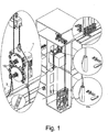
- Fig. 1 represents a situation according to the invention where an old elevator hoisting rope 3 is being replaced with a new hoisting rope 7.
- the elevator in question is an elevator with machine above and provided with a counterweight and a machine room.
- the new hoisting ropes 7 are placed on the topmost landing, from where they are passed to the elevator car 4 and to a rope feed device 1 acting on the hoisting ropes at a point near the car.
- Another way of implementing the roping of a 1:1 suspended elevator is a situation where the elevator car 4 and counterweight 5 are initially secured in place in the elevator shaft oppositely to each other. After that, the elevator car 4 is raised by utilizing one or two supporting ropes, leaving the other hoisting ropes slack. This is implemented by utilizing a supporting rope to raise the car, because the elevator safety coefficients in elevator operation are so high that even a single rope will support the car and counterweight with a reasonable reliability. If necessary, two hoisting ropes may be used. Thus, no scaffolding is needed when ropes are being fastened to the counterweight. In the method, it is possible to use either rope clamps, a rope frog or a suitable rope clip.
- the ropes are replaced one at a time, starting from the ropes left slack. Once the other ropes have been changed, the elevator car is lowered so that it becomes supported by the new ropes, whereupon the ropes previously used to support the car are replaced and finally the rope tensions are equalized.
- the roping is so implemented that the method comprises the steps of
- the rope is fed in a controlled manner into the shaft by utilizing a rope feed device.
- the rope feed device can be placed on the overhead beam of the car, on the machine room floor or mounted hanging in the shaft.
- the roping of a new 1:1 elevator is preferably carried out with the car top leveled with the topmost landing while the counterweight is resting on the buffers in a manner corresponding to the configuration according to the example in Fig. 1 .
- the roping of a new 2:1 suspended elevator is carried out as follows.
- the rope is lowered as a loop, but the end to be attached to the counterweight is fastened beforehand to a rope rod.
- the loop reaches the counterweight, it is passed round a diverting pulley and the rope is pulled tight by means of a rope feed device, whereupon the rope portion to be connected to the car is fastened to the rope rod.
- the change is carried out by pulling the rope by means of the rope feed device.
- the rope reels may be placed on the landing, in the car or on the top of the car.
- the new and old ropes are joined together by a splice.
- the rope change can also be carried out with the car positioned at a high level and the counterweight supported by logs.
- the rope splice 6 is formed by a metal sleeve pressed onto the rope.
- the splice is provided with bevels and a shoulder left inside the sleeve to allow easier mounting of the rope.
- the splice element is provided with holes through which it is possible to see when the rope is in position ready for pressing. Striation provided on the sleeve indicates the area where the sleeve is to be pressed.
- the rope feed apparatus 1 is placed in position by advancing the apparatus 1 to its position in the elevator shaft by utilizing a rope in the elevator shaft.
- the device can be set to climb along a stationary rope available in the elevator shaft.
- the rope may be one already existing in the elevator shaft, but it is also possible to mount for this purpose an auxiliary rope in the elevator shaft.
- the method may thus comprise a step whereby an auxiliary rope is mounted in the elevator shaft.
- the removal of the rope feed device in the elevator shaft to a location where the rope feed device is to be used for rope replacement or installation work is preferably performed in conjunction with other operations described in this application. This accelerates the work.
- the method is preferably implemented using an apparatus 1 as described elsewhere in the application, said apparatus being e.g.
- the feed disc used in the method preferably comprises discs 28,29 between which the rope is passed and which are pressed together by spring force applied to the area of the centers of revolution.
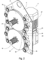
- Fig. 2 is a diagram representing the rope feed apparatus 1 of the invention.
- the rope feed apparatus of the invention is based on friction feed, which is accomplished by applying a controlled spring force against one or more two-part feed discs so that the discs 28, 29 are pressed towards each other.
- the discs 28, 29 are so designed that the rope tends to run on the rim of the feed disc. This is preferably implemented by beveling at least those of the circumferential edges of the discs which face towards each other, thus leaving between the discs 28, 29 a gap that widens towards the circumference, as visualized in Fig. 2 .
- the apparatus comprises guide rollers 25 placed along the circumference of the discs to keep the rope between the discs 28, 29 during the pulling operation.
- the rope is deflected so that a controlled contact between the rope and the feed disc 30, 31 is achieved.
- the grip of the apparatus is based on a spring force, which can be produced in a controlled and repeatable manner after the rope has been mounted and which is implemented using a tightenable spring 19.
- the tightenable spring is preferably disposed as visualized in Figs. 1 and 2 outside the disc pack formed by the discs 28, 29, coaxially on the axis of revolution of the discs to press the discs towards each other.
- the rope groove formed between the discs 28, 29 can adapt itself to variations in rope thickness, because the discs 28 and 29 are axially movable relative to each other against the spring force of the tightenable spring 19.
- the spring is preferably tightenable by a bolt as visualized in the figures.
- the tightening capacity of the bolt of the tightenable spring 19 is preferably so designed that the bolt is always screwed all the way in. This ensures that the grip force of the apparatus is independent of the installer, because variations due to tightening can be avoided.
- the rope feed apparatus may comprise more than one feed disc.
- a power transmission means 48 which is e.g. a chain, belt, cogged belt or pinion.
- the guide rollers 25 are preferably disposed on two sides of the feed disc 30,31 at mutually opposite positions.
- the rope feed apparatus 1 can move the ropes on opposite sides of the feed disc simultaneously in opposite directions.
- the device can also be so implemented that only one side is utilized, in which case no rollers are needed on the other side.
- three guide rollers are shown on either side of the feed disc, but it is obvious that the device may have a different number of them, e.g. one or more, but preferably two rollers on either side.
- the rollers can be so implemented that they extend partially between the discs 28, 29.
- the rope can thus be caused to run deeper between the discs 28, 29, which will allow especially the rope splice to pass through more easily.
- This can be implemented by making the guide roller 25 narrow enough to allow it to go between the discs 28, 29.
- the guide roller becomes narrower towards the circumference or has on its outer surface a ridge narrower than the gap between the feed discs.
- a further possible implementation is to mount around the guide roller 25 a separate ferrule to form a narrow portion on the circumference of the discs.
- the rope reel according to the method can be arranged to be operated in synchronism with the rope pulling device.
- the rope reel may be motorized, in which case the reel is preferably started automatically when the pulling machine is operated, or it can be constructed to exert a continuous pull on the rope with a given force.
- the reel is used for automatic reeling up of the old rope.
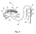
- Fig. 3 illustrates an embodiment of the rope feed apparatus of the invention, wherein the rope feed device 1 used also comprises an equipment 50 for collecting the old rope without a separate reeling motor by an arrangement where a collecting container (21) is adapted to be rotated by the pushing force of the rope (3b) being collected.
- the equipment 50 comprises a guide element 45, which in the embodiment described here is e.g. a plastic tube, fitted to be fastened by its first or free end 40 to the upper part of the feed device 1 by means of a fastening element 55.
- the fastening element 55 may be e.g. a sleeve through which the hoisting rope 3b is passed into the guide element 45 when the feed device 1 starts pulling the rope.
- the equipment 50 additionally comprises a collecting container 21, which can be placed on its supporting structure 23 e.g. on a landing floor or in some other suitable location.
- the collecting container 21 is a cylindrical container provided with a bottom and a vertically oriented barrel, substantially open at the top. To ensure that the old rope will remain firmly in the collecting container 21 during the replacement, it is possible to utilize the shape of the barrel of the collecting container or separate guide elements.
- the barrel may have e.g. the shape of an upwards tapering cone, or the upper edge of the barrel may be provided with an inward bend of trough-like or similar form.
- the supporting structure 23 comprises four supporting legs made of e.g. metal and joined together under the center of the collecting container 21, and the collecting container 21 is fastened to the supporting structure 23 substantially by the center of its bottom by means of a rotational axle 59 and a fastening element 47 so that the collecting container 21 can rotate freely about its substantially vertical rotational axle 59.
- a supporting element 46 Attached by its first end to one of the legs of the supporting structure 23 is a supporting element 46, which is also made of e.g. metal.
- the free end of the supporting element 46 is fitted to extend suitably over the collecting container 21 and the second end 51 of the guide element 45 is attached to the free end of the supporting element 46 in an oblique position in both vertical and horizontal directions relative to the inner surface of the cylindrical part of the collecting container.
- the second end 51 of the guide element 45 is at an angle to the inner surface of the cylindrical part such that the rope coming through the guide element meets the inner surface of the barrel of the collecting container 21 substantially tangentially while being simultaneously directed downwards.
- the operation of the equipment 50 is such that when the feed device 1 starts pulling out the old hoisting rope 3b while at the same time pulling the new hoisting rope 3a into position, the feed device 1 pushes the old hoisting rope 3b into the guide element 45 from the first end of the guide element. After the feed device 1 has pulled the new rope through some distance, the old hoisting rope 3b has moved inside the guide element 45 to the second end 51 of the guide element.
- the rope feed device 1 need not be directly attached to the guide element 45 as shown in Fig. 3 or placed in its vicinity. In such situations, the rope is passed through the guide element 45 into the collecting container 21 by gravity and the feed device 1 may be placed elsewhere in the elevator shaft than in the vicinity of the guide element 45 to feed the rope.
- the rope is collected e.g. as follows: First, the rope 3b is passed into the guide element 45 through the first end 40 of the guide element. After this, the rope 3b is pushed forward inside the guide element 45 until the end of the rope 3b emerges from the second end 51 of the guide element. From here, the rope 3b is pushed into the collecting container 21 at a suitable downward oblique angle so that the rope meets the inner surface of the collecting container 21 and the collecting container 21 is caused to revolve about its rotational axle 59 by the thrust of the rope 3b. This action of pushing the rope 3b into the collecting container 21 is continued for a desired period of time, the rope 3b being thus neatly coiled up inside the collecting container 21.
- the collecting container 21 can also be provided with a plastic bag or a corresponding bag, in which case the old hoisting rope is adapted to be coiled up directly in the bag in the collecting container 21. This allows the old rope to be neatly collected, and once the whole rope is in the bag, the bag with the rope is removed and a new bag is placed in the collecting container for the next rope. In the bag, the rope can be easily conveyed to a further treatment stage.
- the guide element may have some other form.
- the guide element may preferably have e.g. a trough-like shape such that the rope will be guided into the collecting container along the bottom and side edges of the trough of the guide element.
- the feed device can be disposed in a different place than where it is placed in the above description.
- the feed device can thus be secured to any supporting structure suited for the situation.
- the collecting container may also be a basket or equivalent.
- the collecting container may be a temporary container constructed in a frame, e.g. a container with a separate bottom and a side wall element bendable inside the frame.
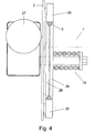
- rope replacement can in practice be implemented in such manner that the rope feed device 1 in Fig. 3 feeds new rope into the elevator system while at the same time feeding out old rope, so that on one side of the feed discs the rope is moved upwards and on the other side downwards.
- Fig. 3 illustrates a situation where the old rope 3b is being fed upwards into the guide element 45. In the figure, it would be possible to simultaneously feed a new rope downwards by the left-hand edge of the feed disc 30, the new rope being attached to the old rope so that it is passed through the route whereby the old rope is removed.
- the rope feed device of the invention can be used in all situations where there is a need to pull or feed a rope in a controlled manner from/into an elevator shaft or to perform both actions simultaneously.
Landscapes
- Lift-Guide Devices, And Elevator Ropes And Cables (AREA)
- Ropes Or Cables (AREA)
- Harvesting Machines For Root Crops (AREA)
- Coiling Of Filamentary Materials In General (AREA)
- Saccharide Compounds (AREA)
- Ultra Sonic Daignosis Equipment (AREA)
- Sampling And Sample Adjustment (AREA)
Claims (14)
- Beseilungsverfahren zum Ersetzen, Installieren und/oder Wiederbeseilen der Hebeseile (3) eines Treibscheibenaufzugs, welcher Aufzug eine Aufzugskabine (4) hat, die wenigstens teilweise an einem Satz von Hebeseilen (3) aufgehängt ist, welcher Satz von Hebeseilen (3) einen oder mehrere parallele Seile enthält, wobei die Aufzugskabine mittels der Seile (3) bewegt wird, und wobei eine Seilzufuhrvorrichtung (1), die auf die Hebeseile (3) wirkt, verwendet wird, um dem Aufzug ein neues Seil zuzuführen und/oder um ein möglicherweise altes Hebeseil herauszuziehen, um Platz zu machen für ein neues Seil, dadurch gekennzeichnet, dass eine Seilzufuhrvorrichtung verwendet wird, die eine Zufuhrscheibe (30, 31) enthält, die wiederum Scheiben (28, 29) hat, zwischen welchen das Seil geführt ist, und welche mittels Federkraft zusammengepresst sind, die in dem Bereich der Drehachse aufgebracht wird.
- Verfahren nach Anspruch 1, dadurch gekennzeichnet, dass das Verfahren zum Ersetzen und/oder Wiederbeseilen der Aufzugsseile (3) eines Aufzugs folgende Schritte aufweist:j) Festlegen der Aufzugskabine (4) und seines möglicherweise vorhandenen Gegengewichts (5) in Position,k) Lockern der Hebeseile (3), vorzugsweise durch Anheben der Aufzugskabine um eine erforderliche Distanz,l) Einsetzen der Seilzufuhrvorrichtung (1), um auf die Hebeseile (3) zu wirken, m) Freigeben beider Enden der Hebeseile (3) von ihren Verankerungen,n) Verbinden des neuen zuzuführenden Seils (7) mit einem Ende des alten Seils (3), das aus dem Aufzugsschacht herausgezogen werden soll, mittels eines Seilspleiß (6),o) Zuführen des neuen Seils in den Aufzug und Herausziehen des alten Hebeseils (3) mittels der Seilzufuhrvorrichtung (1),p) Befestigen des neuen Hebeseils (7) an beiden Enden an den finalen Verankerungen,q) Wiederholen der Schritte b) - g) für jedes Seil in dem Satz an Hebeseilen,r) Entfernen der Seilzufuhrvorrichtung (1) und Freigeben der Aufzugskabine (4) und seines möglichen Gegengewichts (5) von dem gesicherten Status, um sie durch das neue Hebeseil (7) tragen zu lassen.
- Verfahren nach Anspruch 1, dadurch gekennzeichnet, dass das Verfahren zum Installieren der Aufzugsseile folgende Schritte enthält:h) Festlegen der Aufzugskabine (4) und seines möglichen Gegengewichts (5) in ihren Installationspositionen,i) Festlegen der Seilzufuhrvorrichtung in Position in dem Aufzugsschacht, Maschinenraum oder einem anderen geeigneten Platz,j) Anschlagen eines Aufzughebeseils, so dass es durch die Seilzufuhrvorrichtung (1) geht,k) Zuführen des Seils zu einem möglichen Gegengewicht durch die Seilzufuhrvorrichtung (1) und Befestigen des Seils an seinem finalen Verankerungspunkt,l) Festlegen des anderen Endes des Seils an seinem finalen Verankerungspunkt,m) Freigeben der Seilzufuhrvorrichtung und Wiederholen der Schritte b) - e), abhängig von der Anzahl der Hebeseile,n) Entfernen der Seilzufuhrvorrichtung (1) und Spannen der Hebeseile auf ihre finale Spannung.
- Verfahren nach einem der vorhergehenden Ansprüche, dadurch gekennzeichnet, dass das neue Hebeseil (7) dem Aufzugsschacht und der Seilzufuhrvorrichtung (1) von einer Rolle zugeführt wird, welche Rolle vorzugsweise an dem nähesten Stockwerk angeordnet ist, in der Aufzugskabine oder ihrer Nähe oder in dem Aufzugmaschinenraum, und dass das alte zu ersetzende oder wieder aufzuziehende Seil (3) auf eine Seilrolle gezogen wird, die vorzugsweise motorisiert ist und/oder in Synchronisation mit der Seilzufuhrvorrichtung (1) des Aufzugs arbeitet.
- Verfahren nach einem der vorhergehenden Ansprüche 1 - 3, dadurch gekennzeichnet, dass in dem Verfahren das Seil in einem Sammelbehälter (21) gesammelt und das Seil (3b) so in den Sammelbehälter (21) gedrückt wird, dass der Sammelbehälter (21) dazu gebracht wird, sich um eine Drehachse (59) durch den Stoß des Seiles (3b) zu drehen.
- Verfahren nach Anspruch 5, dadurch gekennzeichnet, dass das zu sammelnde Seil (3b), bevor es in den Sammelbehälter (21) gedrückt wird, in ein rohrförmiges Führungselement (45) geführt wird, welches in der Lage ist, das Seil (3b) in einem im Wesentlichen nach unten weisenden, geneigten, spitzen Winkel in den Sammelbehälter (21) zu führen.
- Verfahren nach Anspruch 5 oder 6, dadurch gekennzeichnet, dass das in Verbindung mit dem Ersatz eines Aufzugsseils zu sammelnde Seil (3b) das alte Hebeseil (3b) ist, welches durch das Führungselement (45) durch die Seilzufuhrvorrichtung (1) oder mittels Schwerkraft in den Sammelbehälter (21) gedrückt wird, während das neue Seil mittels des alten Seils in Position gezogen wird.
- Verfahren nach einem der vorhergehenden Ansprüche 1 - 7, dadurch gekennzeichnet, dass die Seilzufuhrvorrichtung in Position bewegt wird, indem sie sich an ihre Position in dem Aufzugsschacht annähert entlang eines Seils, welches in Position in dem Aufzugsschacht angeordnet ist.
- Seilzufuhrvorrichtung (1) zum Ersetzen, Installieren oder Wiederbeseilen des Hebeseils (3) eines Aufzugs, welcher Aufzug eine Aufzugskabine (4) hat, die wenigstens teilweise an einem Satz von Hebeseilen (3) aufgehängt ist, welcher Satz von Seilen (3) ein oder mehrere parallele Seile umfasst, wobei die Aufzugskabine mittels der Seile (3) bewegt wird, wobei die Seilzufuhrvorrichtung (1) wenigstens eine Basis (2) mit wenigstens einer darauf montierten Zufuhrscheibe (30, 31) hat, welche Zufuhrscheibe (30, 31) das Hebeseil (3) greift und an welche Zufuhrscheibe (30, 31) das Hebeseil eingepasst werden kann, wenigstens eine Führungsrolle (25), um das Hebeseil auf der Zufuhrscheibe (30, 31) in Position zu halten, ein Spannelement (19), um die Zufuhrscheibe (30, 31) relativ zur Führungsrolle (25) zu bewegen und sie in Position an der Basis (2) vorzuspannen, und zusätzlich wenigstens einen elektrischen Motor (27), der in der Vorrichtung vorgesehen ist, um die Zufuhrscheibe (30, 31) zu drehen, dadurch gekennzeichnet, dass die Zufuhrscheibe (30, 31) der Seilzufuhrvorrichtung (1) wenigstens zwei Scheiben (28, 29) enthält, zwischen denen die Hebeseile gepresst werden können, um eine Friktion zwischen dem Hebeseil und der Zufuhrscheibe zu erzeugen, wobei wenigstens eine Scheibe (28, 29) relativ zu der Führungsrolle (25) bewegbar ist, um es dem Hebeseil zu ermöglichen, in der Vorrichtung (1) gegriffen zu werden und in Position durch ein Spannelement (19) gespannt zu werden, welches vorzugsweise eine festziehbare Feder ist.
- Seilzufuhrvorrichtung nach Anspruch 9, dadurch gekennzeichnet, dass die Vorrichtung wenigstens zwei oder mehrere Zufuhrscheiben (30, 31) hat, und dass die Vorrichtung zwei oder mehrere Führungsrollen (25) hat.
- Seilzufuhrvorrichtung nach einem der vorhergehenden Ansprüche 9 - 10, dadurch gekennzeichnet, dass die festziehbare Feder (19) oder dergleichen außerhalb der Zufuhrscheibe (30, 31) angeordnet ist, welche durch die Scheiben (28, 29) gebildet ist, um die Scheiben (28, 29) gegeneinander zu drücken.
- Seilzufuhrvorrichtung nach einem der vorhergehenden Ansprüche 9 - 11, dadurch gekennzeichnet, dass die festziehbare Feder (19) oder dergleichen koaxial zu der Zufuhrscheibe (30, 31) vorgesehen ist.
- Seilzufuhrvorrichtung nach einem der vorhergehenden Ansprüche 9 - 12, dadurch gekennzeichnet, dass die Seilzufuhrausrüstung des Aufzugs eine Seilrolle umfasst, die mit einem Motor versehen ist und an ihrer Stelle im Aufzugsschacht, auf einem Stockwerk oder irgendeinem anderen geeigneten Platz angeordnet ist, um das alte Hebeseil aufzuwickeln, und dass die Seilrolle geeignet ist, in Synchronisation mit der Seilziehvorrichtung zu arbeiten.
- Seilzufuhrvorrichtung nach einem der vorhergehenden Ansprüche 9 - 13, dadurch gekennzeichnet, dass die Seilzufuhrausrüstung des Aufzugs einen Sammelbehälter (21) enthält, der im Aufzugsschacht, auf einem Stockwerk oder irgendeinem anderen geeigneten Platz angeordnet ist, wobei das aufzusammelnde Seil (3b) in dem Container angeordnet werden kann, dass der Sammelbehälter (21) mit einer Drehachse (59) versehen ist, und dass der Sammelbehälter (21) um seine Drehachse (59) durch die Stoßkraft des zu sammelnden Seiles (3b) gedreht werden kann.
Applications Claiming Priority (2)
| Application Number | Priority Date | Filing Date | Title |
|---|---|---|---|
| FI20060371A FI119320B (fi) | 2006-04-18 | 2006-04-18 | Köydensyöttölaitteisto hissin nostoköyden asentamiseksi, vaihtamiseksi ja/tai uudelleenköysittämiseksi |
| PCT/FI2007/000100 WO2007118928A1 (en) | 2006-04-18 | 2007-04-17 | Roping method and apparatus |
Publications (3)
| Publication Number | Publication Date |
|---|---|
| EP2007668A1 EP2007668A1 (de) | 2008-12-31 |
| EP2007668A4 EP2007668A4 (de) | 2009-04-08 |
| EP2007668B1 true EP2007668B1 (de) | 2012-04-11 |
Family
ID=36293765
Family Applications (2)
| Application Number | Title | Priority Date | Filing Date |
|---|---|---|---|
| EP07730569A Not-in-force EP2007668B1 (de) | 2006-04-18 | 2007-04-17 | Seilanordnungsverfahren und -vorrichtung |
| EP07730570.4A Not-in-force EP2007669B1 (de) | 2006-04-18 | 2007-04-17 | Verfahren und gerät zum aufwickeln eines seils |
Family Applications After (1)
| Application Number | Title | Priority Date | Filing Date |
|---|---|---|---|
| EP07730570.4A Not-in-force EP2007669B1 (de) | 2006-04-18 | 2007-04-17 | Verfahren und gerät zum aufwickeln eines seils |
Country Status (11)
| Country | Link |
|---|---|
| US (2) | US8602175B2 (de) |
| EP (2) | EP2007668B1 (de) |
| JP (2) | JP5517609B2 (de) |
| CN (2) | CN101472828B (de) |
| AT (1) | ATE553054T1 (de) |
| AU (2) | AU2007239439B2 (de) |
| CA (2) | CA2648727C (de) |
| DK (1) | DK2007668T3 (de) |
| ES (1) | ES2382395T3 (de) |
| FI (1) | FI119320B (de) |
| WO (2) | WO2007118928A1 (de) |
Cited By (1)
| Publication number | Priority date | Publication date | Assignee | Title |
|---|---|---|---|---|
| CN110844817A (zh) * | 2019-12-19 | 2020-02-28 | 三一重机有限公司 | 一种卷扬机及起吊装置 |
Families Citing this family (24)
| Publication number | Priority date | Publication date | Assignee | Title |
|---|---|---|---|---|
| FI20070694A0 (fi) * | 2007-09-11 | 2007-09-11 | Kone Corp | Hissijärjestely |
| ES2342806B1 (es) * | 2008-07-29 | 2011-05-12 | Orona, S. Coop. | Metodo para sustituir cables de aparatos elevadores. |
| FI20090085L (fi) * | 2009-03-06 | 2010-09-30 | Kone Corp | Hissijärjestely ja menetelmä |
| EP2641580B1 (de) | 2012-03-20 | 2020-06-03 | Chordate Medical AB | Elektroaktive Vibrationsvorrichtung |
| FI125124B (fi) * | 2012-05-23 | 2015-06-15 | Kone Corp | Hissijärjestely ja menetelmä |
| DE102012111622A1 (de) * | 2012-11-29 | 2014-06-05 | Thyssenkrupp Elevator Ag | Aufzuganlage für ein im Bau befindliches Gebäude |
| DE102012111778A1 (de) * | 2012-12-04 | 2014-06-05 | Thyssenkrupp Elevator Ag | Seilklemme und Aufzuganlage mit Seilklemme |
| FI125133B (fi) * | 2013-03-20 | 2015-06-15 | Kone Oyj | Hissin asennusjärjestely |
| PL3003951T3 (pl) * | 2013-05-28 | 2017-09-29 | Inventio Ag | Urządzenie hamulcowe cięgna nośnego |
| EP2845832B1 (de) | 2013-09-05 | 2017-07-26 | KONE Corporation | Seilaufbewahrungseinheit, Verfahren zur Installation eines Aufzugs und Verfahren zur Herstellung einer Seilaufbewahrungseinheit |
| EP3034449A1 (de) * | 2014-12-17 | 2016-06-22 | KONE Corporation | Kabelaufbewahrungseinheit und Verfahren zur Installation von Aufzugskabeln |
| CN104743430A (zh) * | 2015-03-26 | 2015-07-01 | 神华集团有限责任公司 | 一种用于更换绞车钢丝绳的装置 |
| CN107512672B (zh) * | 2016-06-18 | 2019-09-10 | 高元书 | 绳索牵引控制方法 |
| JP6820231B2 (ja) * | 2017-05-02 | 2021-01-27 | 三菱電機ビルテクノサービス株式会社 | ロープ引上装置 |
| JP6520989B2 (ja) * | 2017-07-12 | 2019-05-29 | 三菱電機ビルテクノサービス株式会社 | エレベーターのロープ外れ防止治具及びエレベーターのロープ取替方法 |
| EP3533745A1 (de) | 2018-03-01 | 2019-09-04 | KONE Corporation | Verfahren und anordnung zur montage eines aufzugsleistenseils |
| CN110498321B (zh) * | 2018-05-17 | 2022-09-27 | 奥的斯电梯公司 | 补偿线束存储装置、跃层电梯及其使用方法 |
| CN109987480A (zh) * | 2019-04-18 | 2019-07-09 | 福建省特种设备检验研究院 | 一种曳引钢丝绳直径实时检测装置及其检测方法 |
| CN109987479A (zh) * | 2019-04-18 | 2019-07-09 | 福建省特种设备检验研究院 | 一种曳引钢丝绳外径在线实时测量装置及其测量方法 |
| CN110844753B (zh) * | 2019-11-21 | 2021-06-01 | 中国矿业大学 | 一种扁尾绳摆动抑制导向装置及方法 |
| CN111958549A (zh) * | 2020-08-18 | 2020-11-20 | 王倩 | 一种自动拧紧的绞盘防漏油装置 |
| CN111994762A (zh) * | 2020-09-17 | 2020-11-27 | 重庆能投渝新能源有限公司 | 一种立井提升钢丝绳换绳工艺 |
| CN112693977B (zh) * | 2020-12-19 | 2022-11-18 | 龙岩市海德馨汽车有限公司 | 一种车载式自动旁路作业放缆机构及其控制方法 |
| CN113086812B (zh) * | 2021-04-23 | 2023-04-07 | 廊坊凯博建设机械科技有限公司 | 一种吊笼可自动调平的升降机 |
Family Cites Families (46)
| Publication number | Priority date | Publication date | Assignee | Title |
|---|---|---|---|---|
| US177367A (en) * | 1876-05-16 | Improvement in hose-reels | ||
| US1364699A (en) * | 1921-01-04 | Theatrical apparatus | ||
| US1305899A (en) * | 1919-06-03 | A corpora | ||
| US972222A (en) * | 1910-02-23 | 1910-10-11 | Henry T Curtwright | Hose-reel. |
| US2220481A (en) * | 1938-03-25 | 1940-11-05 | Joy Fastener Company | Coiling and nesting device for flexible strip material |
| US2299521A (en) * | 1941-03-17 | 1942-10-20 | Frank P Zierden | Hose reel |
| US2300243A (en) * | 1941-06-07 | 1942-10-27 | Frank P Zierden | Hose housing |
| US2461079A (en) * | 1948-02-10 | 1949-02-08 | American Chain & Cable Co | Wire rope splice |
| JPS431385Y1 (de) * | 1964-10-24 | 1968-01-23 | ||
| GB1305899A (de) * | 1969-03-11 | 1973-02-07 | ||
| GB1364699A (en) * | 1971-11-19 | 1974-08-29 | Fairey Winches Ltd | Cable winch |
| DE2307370C3 (de) * | 1973-02-15 | 1979-03-29 | Carl 5291 Kupferberg Kaeufer | Seilwinde, insbesondere für Hängegerüste |
| DE2522033C2 (de) * | 1975-05-17 | 1983-01-05 | Greifzug Gesellschaft für Hebezeugbau mbH, 5070 Bergisch-Gladbach | Treibscheibentriebwerk |
| JPS6037028B2 (ja) * | 1978-07-28 | 1985-08-23 | 株式会社日立製作所 | ケ−ブル巻取装置 |
| JPS55117452U (de) * | 1979-02-06 | 1980-08-19 | ||
| JPS55117452A (en) | 1979-03-02 | 1980-09-09 | Sharp Corp | Motor |
| JPS566727A (en) * | 1979-06-29 | 1981-01-23 | Kawasaki Steel Corp | Production of pail-pack-wound wire |
| DE2928078A1 (de) * | 1979-07-12 | 1981-01-29 | Rotzler Gmbh Co | Durchlaufwinde |
| DE3025954A1 (de) * | 1980-07-09 | 1982-02-04 | Emil Wolff, Maschinenfabrik Und Eisengiesserei Gmbh, 4300 Essen | Seilauflegewinde zum auswechseln eines alten foerderseiles |
| DE3243754C2 (de) * | 1982-11-26 | 1994-04-21 | Heinz Haenel | Antriebseinrichtung für ein Zugseil |
| DE3325323A1 (de) * | 1983-07-13 | 1985-01-24 | VMEI Lenin, Sofia/Sofija | Seilwechselmaschine fuer grubenfoerderanlagen |
| ZA86161B (en) * | 1985-01-22 | 1986-08-27 | Sky Climber Europ | Arrangement for lifting and lowering or for pulling loads |
| JPS6279761U (de) * | 1985-11-11 | 1987-05-21 | ||
| US4826100A (en) * | 1988-01-11 | 1989-05-02 | Belliveau Robert C | Device for use in unwinding or rewinding coiled electrical wire |
| JPH0780655B2 (ja) * | 1988-10-26 | 1995-08-30 | 株式会社日立ビルシステムサービス | エレベータのロープ交換方法 |
| JPH031174U (de) * | 1989-05-25 | 1991-01-08 | ||
| JPH0818774B2 (ja) * | 1989-06-13 | 1996-02-28 | 株式会社日立ビルシステムサービス | エレベータの主ロープ交換方法 |
| JP2510732B2 (ja) * | 1989-07-31 | 1996-06-26 | 株式会社日立ビルシステムサービス | 主ロ―プ交換補助装置 |
| JPH07196240A (ja) * | 1992-10-14 | 1995-08-01 | T S:Kk | ロープ送り装置 |
| JPH07133085A (ja) * | 1993-11-10 | 1995-05-23 | Mitsubishi Denki Bill Techno Service Kk | エレベータの主索交換方法 |
| US5566901A (en) * | 1994-12-13 | 1996-10-22 | Wilder; Ray J. | Method and apparatus for winding fire hose |
| US5641138A (en) * | 1995-04-21 | 1997-06-24 | The Servicemaster Company | Trash bag stand |
| JPH10182012A (ja) * | 1996-12-20 | 1998-07-07 | Matsushita Electric Works Ltd | ケーブル受け籠 |
| JP3277486B2 (ja) * | 1998-01-07 | 2002-04-22 | 株式会社日立ビルシステム | 昇降機の既設主索巻取り装置 |
| JP2000086085A (ja) * | 1998-09-10 | 2000-03-28 | Mitsubishi Cable Ind Ltd | 海底ケーブル用コイラー |
| JP4430769B2 (ja) | 1999-12-09 | 2010-03-10 | 信越化学工業株式会社 | セラミックス加熱治具 |
| JP2002003125A (ja) * | 2000-06-16 | 2002-01-09 | Hitachi Building Systems Co Ltd | エレベータの主ロープ交換方法 |
| FR2826352B1 (fr) * | 2001-06-22 | 2003-09-05 | Seb Sa | Guide-cable pour enrouleur de cable d'alimentation electrique d'un appareil menager |
| JP2003040551A (ja) * | 2001-07-31 | 2003-02-13 | Mitsubishi Electric Building Techno Service Co Ltd | エレベータの主索移動装置並びに同装置による主索の撤去方法及び新設方法 |
| JP2003146556A (ja) | 2001-11-14 | 2003-05-21 | Hitachi Building Systems Co Ltd | エレベータの主ロープ交換装置 |
| JP2003238047A (ja) | 2002-02-12 | 2003-08-27 | Hitachi Building Systems Co Ltd | エレベータの主ロープ交換方法および装置 |
| US6807982B1 (en) * | 2003-07-31 | 2004-10-26 | Larry Ames | Hose tub |
| JP2005138917A (ja) * | 2003-11-04 | 2005-06-02 | Ryoden Elevator Construction Ltd | 搬送機の主ロープ交換方法及びその主ロープ交換装置 |
| FI118645B (fi) * | 2004-04-29 | 2008-01-31 | Kone Corp | Menetelmä ja laitteisto vetopyörähissin köyden vaihtamiseksi |
| JP2012056716A (ja) * | 2010-09-09 | 2012-03-22 | Mitsubishi Electric Corp | エレベータの主ロープ交換方法および装置 |
| JP5510301B2 (ja) * | 2010-12-15 | 2014-06-04 | 三菱電機ビルテクノサービス株式会社 | エレベーター用ロープ巻き取り補助具 |
-
2006
- 2006-04-18 FI FI20060371A patent/FI119320B/fi not_active IP Right Cessation
-
2007
- 2007-04-17 EP EP07730569A patent/EP2007668B1/de not_active Not-in-force
- 2007-04-17 ES ES07730569T patent/ES2382395T3/es active Active
- 2007-04-17 CN CN2007800225268A patent/CN101472828B/zh not_active Expired - Fee Related
- 2007-04-17 EP EP07730570.4A patent/EP2007669B1/de not_active Not-in-force
- 2007-04-17 WO PCT/FI2007/000100 patent/WO2007118928A1/en not_active Ceased
- 2007-04-17 WO PCT/FI2007/000101 patent/WO2007118929A1/en not_active Ceased
- 2007-04-17 CA CA2648727A patent/CA2648727C/en not_active Expired - Fee Related
- 2007-04-17 JP JP2009505919A patent/JP5517609B2/ja not_active Expired - Fee Related
- 2007-04-17 AT AT07730569T patent/ATE553054T1/de active
- 2007-04-17 CA CA2648967A patent/CA2648967C/en not_active Expired - Fee Related
- 2007-04-17 JP JP2009505918A patent/JP5465526B2/ja not_active Expired - Fee Related
- 2007-04-17 CN CNA2007800225111A patent/CN101472826A/zh active Pending
- 2007-04-17 DK DK07730569.6T patent/DK2007668T3/da active
- 2007-04-17 AU AU2007239439A patent/AU2007239439B2/en not_active Ceased
- 2007-04-17 AU AU2007239440A patent/AU2007239440B2/en not_active Ceased
-
2008
- 2008-10-17 US US12/253,787 patent/US8602175B2/en not_active Expired - Fee Related
- 2008-10-17 US US12/289,032 patent/US8046890B2/en not_active Expired - Fee Related
Cited By (1)
| Publication number | Priority date | Publication date | Assignee | Title |
|---|---|---|---|---|
| CN110844817A (zh) * | 2019-12-19 | 2020-02-28 | 三一重机有限公司 | 一种卷扬机及起吊装置 |
Also Published As
| Publication number | Publication date |
|---|---|
| JP2009534275A (ja) | 2009-09-24 |
| WO2007118928A1 (en) | 2007-10-25 |
| US20090114483A1 (en) | 2009-05-07 |
| AU2007239440B2 (en) | 2012-12-06 |
| EP2007668A4 (de) | 2009-04-08 |
| AU2007239439A1 (en) | 2007-10-25 |
| WO2007118929A1 (en) | 2007-10-25 |
| JP5465526B2 (ja) | 2014-04-09 |
| DK2007668T3 (da) | 2012-05-07 |
| JP5517609B2 (ja) | 2014-06-11 |
| ES2382395T3 (es) | 2012-06-07 |
| CA2648727A1 (en) | 2007-10-25 |
| CN101472826A (zh) | 2009-07-01 |
| JP2009534274A (ja) | 2009-09-24 |
| AU2007239440A1 (en) | 2007-10-25 |
| EP2007669A1 (de) | 2008-12-31 |
| ATE553054T1 (de) | 2012-04-15 |
| US8602175B2 (en) | 2013-12-10 |
| US20090101448A1 (en) | 2009-04-23 |
| CA2648967A1 (en) | 2007-10-25 |
| CA2648967C (en) | 2016-06-07 |
| AU2007239439B2 (en) | 2012-06-28 |
| US8046890B2 (en) | 2011-11-01 |
| FI20060371L (fi) | 2007-10-19 |
| FI20060371A0 (fi) | 2006-04-18 |
| CN101472828A (zh) | 2009-07-01 |
| CN101472828B (zh) | 2012-05-23 |
| CA2648727C (en) | 2013-12-17 |
| FI119320B (fi) | 2008-10-15 |
| EP2007668A1 (de) | 2008-12-31 |
| EP2007669B1 (de) | 2014-05-07 |
| EP2007669A4 (de) | 2009-04-08 |
Similar Documents
| Publication | Publication Date | Title |
|---|---|---|
| EP2007668B1 (de) | Seilanordnungsverfahren und -vorrichtung | |
| AU2007247066B2 (en) | A method for replacing the hoisting roping of an elevator and a traction appliance arrangement used in the replacement | |
| CN104024141A (zh) | 电梯设备和方法 | |
| EP1591406B2 (de) | Verfahren zum Auswechseln des Seiles von einem Treibscheibenaufzug | |
| JP2562071B2 (ja) | クレーンのワイヤロープ取替方法 | |
| CN111453530B (zh) | 一种起升钢丝绳更换装置及其控制方法 | |
| HK1231453A1 (zh) | 用於安装或拆卸电梯绳索的装置和方法 | |
| JP2003128359A (ja) | エレベータのロープ掛け方法 | |
| JPH0818774B2 (ja) | エレベータの主ロープ交換方法 | |
| US7832712B1 (en) | Cable puller for lifting wire rope and electric cords and associated method | |
| JP2004083278A (ja) | エレベータの主ロープ交換装置 | |
| HK1201246B (en) | Elevator arrangement and method | |
| JPH11171432A (ja) | 昇降装置におけるケーブルの振れ止め装置 |
Legal Events
| Date | Code | Title | Description |
|---|---|---|---|
| PUAI | Public reference made under article 153(3) epc to a published international application that has entered the european phase |
Free format text: ORIGINAL CODE: 0009012 |
|
| 17P | Request for examination filed |
Effective date: 20081013 |
|
| AK | Designated contracting states |
Kind code of ref document: A1 Designated state(s): AT BE BG CH CY CZ DE DK EE ES FI FR GB GR HU IE IS IT LI LT LU LV MC MT NL PL PT RO SE SI SK TR |
|
| AX | Request for extension of the european patent |
Extension state: AL BA HR MK RS |
|
| A4 | Supplementary search report drawn up and despatched |
Effective date: 20090305 |
|
| 17Q | First examination report despatched |
Effective date: 20090924 |
|
| GRAP | Despatch of communication of intention to grant a patent |
Free format text: ORIGINAL CODE: EPIDOSNIGR1 |
|
| DAX | Request for extension of the european patent (deleted) | ||
| GRAS | Grant fee paid |
Free format text: ORIGINAL CODE: EPIDOSNIGR3 |
|
| GRAA | (expected) grant |
Free format text: ORIGINAL CODE: 0009210 |
|
| AK | Designated contracting states |
Kind code of ref document: B1 Designated state(s): AT BE BG CH CY CZ DE DK EE ES FI FR GB GR HU IE IS IT LI LT LU LV MC MT NL PL PT RO SE SI SK TR |
|
| REG | Reference to a national code |
Ref country code: GB Ref legal event code: FG4D |
|
| REG | Reference to a national code |
Ref country code: CH Ref legal event code: EP |
|
| REG | Reference to a national code |
Ref country code: AT Ref legal event code: REF Ref document number: 553054 Country of ref document: AT Kind code of ref document: T Effective date: 20120415 |
|
| REG | Reference to a national code |
Ref country code: DK Ref legal event code: T3 |
|
| REG | Reference to a national code |
Ref country code: IE Ref legal event code: FG4D |
|
| REG | Reference to a national code |
Ref country code: DE Ref legal event code: R096 Ref document number: 602007021897 Country of ref document: DE Effective date: 20120606 |
|
| REG | Reference to a national code |
Ref country code: ES Ref legal event code: FG2A Ref document number: 2382395 Country of ref document: ES Kind code of ref document: T3 Effective date: 20120607 |
|
| REG | Reference to a national code |
Ref country code: SE Ref legal event code: TRGR |
|
| REG | Reference to a national code |
Ref country code: NL Ref legal event code: T3 |
|
| LTIE | Lt: invalidation of european patent or patent extension |
Effective date: 20120411 |
|
| PG25 | Lapsed in a contracting state [announced via postgrant information from national office to epo] |
Ref country code: FI Free format text: LAPSE BECAUSE OF FAILURE TO SUBMIT A TRANSLATION OF THE DESCRIPTION OR TO PAY THE FEE WITHIN THE PRESCRIBED TIME-LIMIT Effective date: 20120411 Ref country code: CY Free format text: LAPSE BECAUSE OF FAILURE TO SUBMIT A TRANSLATION OF THE DESCRIPTION OR TO PAY THE FEE WITHIN THE PRESCRIBED TIME-LIMIT Effective date: 20120411 Ref country code: LT Free format text: LAPSE BECAUSE OF FAILURE TO SUBMIT A TRANSLATION OF THE DESCRIPTION OR TO PAY THE FEE WITHIN THE PRESCRIBED TIME-LIMIT Effective date: 20120411 Ref country code: IS Free format text: LAPSE BECAUSE OF FAILURE TO SUBMIT A TRANSLATION OF THE DESCRIPTION OR TO PAY THE FEE WITHIN THE PRESCRIBED TIME-LIMIT Effective date: 20120811 Ref country code: PL Free format text: LAPSE BECAUSE OF FAILURE TO SUBMIT A TRANSLATION OF THE DESCRIPTION OR TO PAY THE FEE WITHIN THE PRESCRIBED TIME-LIMIT Effective date: 20120411 |
|
| PG25 | Lapsed in a contracting state [announced via postgrant information from national office to epo] |
Ref country code: SI Free format text: LAPSE BECAUSE OF FAILURE TO SUBMIT A TRANSLATION OF THE DESCRIPTION OR TO PAY THE FEE WITHIN THE PRESCRIBED TIME-LIMIT Effective date: 20120411 Ref country code: LV Free format text: LAPSE BECAUSE OF FAILURE TO SUBMIT A TRANSLATION OF THE DESCRIPTION OR TO PAY THE FEE WITHIN THE PRESCRIBED TIME-LIMIT Effective date: 20120411 Ref country code: MC Free format text: LAPSE BECAUSE OF NON-PAYMENT OF DUE FEES Effective date: 20120430 Ref country code: GR Free format text: LAPSE BECAUSE OF FAILURE TO SUBMIT A TRANSLATION OF THE DESCRIPTION OR TO PAY THE FEE WITHIN THE PRESCRIBED TIME-LIMIT Effective date: 20120712 Ref country code: PT Free format text: LAPSE BECAUSE OF FAILURE TO SUBMIT A TRANSLATION OF THE DESCRIPTION OR TO PAY THE FEE WITHIN THE PRESCRIBED TIME-LIMIT Effective date: 20120813 |
|
| PGFP | Annual fee paid to national office [announced via postgrant information from national office to epo] |
Ref country code: ES Payment date: 20120525 Year of fee payment: 6 |
|
| PG25 | Lapsed in a contracting state [announced via postgrant information from national office to epo] |
Ref country code: SK Free format text: LAPSE BECAUSE OF FAILURE TO SUBMIT A TRANSLATION OF THE DESCRIPTION OR TO PAY THE FEE WITHIN THE PRESCRIBED TIME-LIMIT Effective date: 20120411 Ref country code: CZ Free format text: LAPSE BECAUSE OF FAILURE TO SUBMIT A TRANSLATION OF THE DESCRIPTION OR TO PAY THE FEE WITHIN THE PRESCRIBED TIME-LIMIT Effective date: 20120411 Ref country code: RO Free format text: LAPSE BECAUSE OF FAILURE TO SUBMIT A TRANSLATION OF THE DESCRIPTION OR TO PAY THE FEE WITHIN THE PRESCRIBED TIME-LIMIT Effective date: 20120411 Ref country code: EE Free format text: LAPSE BECAUSE OF FAILURE TO SUBMIT A TRANSLATION OF THE DESCRIPTION OR TO PAY THE FEE WITHIN THE PRESCRIBED TIME-LIMIT Effective date: 20120411 |
|
| PLBE | No opposition filed within time limit |
Free format text: ORIGINAL CODE: 0009261 |
|
| STAA | Information on the status of an ep patent application or granted ep patent |
Free format text: STATUS: NO OPPOSITION FILED WITHIN TIME LIMIT |
|
| 26N | No opposition filed |
Effective date: 20130114 |
|
| REG | Reference to a national code |
Ref country code: DE Ref legal event code: R097 Ref document number: 602007021897 Country of ref document: DE Effective date: 20130114 |
|
| REG | Reference to a national code |
Ref country code: DE Ref legal event code: R082 Ref document number: 602007021897 Country of ref document: DE Representative=s name: GRAF GLUECK KRITZENBERGER, DE Ref country code: DE Ref legal event code: R082 Ref document number: 602007021897 Country of ref document: DE Representative=s name: GLUECK - KRITZENBERGER PATENTANWAELTE PARTGMBB, DE |
|
| PG25 | Lapsed in a contracting state [announced via postgrant information from national office to epo] |
Ref country code: MT Free format text: LAPSE BECAUSE OF FAILURE TO SUBMIT A TRANSLATION OF THE DESCRIPTION OR TO PAY THE FEE WITHIN THE PRESCRIBED TIME-LIMIT Effective date: 20120411 Ref country code: BG Free format text: LAPSE BECAUSE OF FAILURE TO SUBMIT A TRANSLATION OF THE DESCRIPTION OR TO PAY THE FEE WITHIN THE PRESCRIBED TIME-LIMIT Effective date: 20120711 |
|
| PGFP | Annual fee paid to national office [announced via postgrant information from national office to epo] |
Ref country code: DK Payment date: 20130418 Year of fee payment: 7 Ref country code: IE Payment date: 20130422 Year of fee payment: 7 Ref country code: BE Payment date: 20130418 Year of fee payment: 7 Ref country code: SE Payment date: 20130418 Year of fee payment: 7 |
|
| PGFP | Annual fee paid to national office [announced via postgrant information from national office to epo] |
Ref country code: NL Payment date: 20130418 Year of fee payment: 7 |
|
| PG25 | Lapsed in a contracting state [announced via postgrant information from national office to epo] |
Ref country code: TR Free format text: LAPSE BECAUSE OF FAILURE TO SUBMIT A TRANSLATION OF THE DESCRIPTION OR TO PAY THE FEE WITHIN THE PRESCRIBED TIME-LIMIT Effective date: 20120411 |
|
| PG25 | Lapsed in a contracting state [announced via postgrant information from national office to epo] |
Ref country code: LU Free format text: LAPSE BECAUSE OF NON-PAYMENT OF DUE FEES Effective date: 20120417 |
|
| PG25 | Lapsed in a contracting state [announced via postgrant information from national office to epo] |
Ref country code: HU Free format text: LAPSE BECAUSE OF FAILURE TO SUBMIT A TRANSLATION OF THE DESCRIPTION OR TO PAY THE FEE WITHIN THE PRESCRIBED TIME-LIMIT Effective date: 20070417 |
|
| REG | Reference to a national code |
Ref country code: DK Ref legal event code: EBP Effective date: 20140430 |
|
| REG | Reference to a national code |
Ref country code: NL Ref legal event code: V1 Effective date: 20141101 |
|
| REG | Reference to a national code |
Ref country code: SE Ref legal event code: EUG |
|
| REG | Reference to a national code |
Ref country code: IE Ref legal event code: MM4A |
|
| PG25 | Lapsed in a contracting state [announced via postgrant information from national office to epo] |
Ref country code: SE Free format text: LAPSE BECAUSE OF NON-PAYMENT OF DUE FEES Effective date: 20140418 |
|
| PG25 | Lapsed in a contracting state [announced via postgrant information from national office to epo] |
Ref country code: NL Free format text: LAPSE BECAUSE OF NON-PAYMENT OF DUE FEES Effective date: 20141101 |
|
| PG25 | Lapsed in a contracting state [announced via postgrant information from national office to epo] |
Ref country code: IE Free format text: LAPSE BECAUSE OF NON-PAYMENT OF DUE FEES Effective date: 20140417 Ref country code: DK Free format text: LAPSE BECAUSE OF NON-PAYMENT OF DUE FEES Effective date: 20140430 |
|
| REG | Reference to a national code |
Ref country code: FR Ref legal event code: PLFP Year of fee payment: 10 |
|
| PG25 | Lapsed in a contracting state [announced via postgrant information from national office to epo] |
Ref country code: ES Free format text: LAPSE BECAUSE OF NON-PAYMENT OF DUE FEES Effective date: 20140418 |
|
| REG | Reference to a national code |
Ref country code: FR Ref legal event code: PLFP Year of fee payment: 11 |
|
| PG25 | Lapsed in a contracting state [announced via postgrant information from national office to epo] |
Ref country code: BE Free format text: LAPSE BECAUSE OF NON-PAYMENT OF DUE FEES Effective date: 20140430 |
|
| REG | Reference to a national code |
Ref country code: FR Ref legal event code: PLFP Year of fee payment: 12 |
|
| PGFP | Annual fee paid to national office [announced via postgrant information from national office to epo] |
Ref country code: DE Payment date: 20200420 Year of fee payment: 14 Ref country code: FR Payment date: 20200420 Year of fee payment: 14 Ref country code: CH Payment date: 20200420 Year of fee payment: 14 |
|
| PGFP | Annual fee paid to national office [announced via postgrant information from national office to epo] |
Ref country code: GB Payment date: 20200427 Year of fee payment: 14 Ref country code: IT Payment date: 20200423 Year of fee payment: 14 |
|
| PGFP | Annual fee paid to national office [announced via postgrant information from national office to epo] |
Ref country code: AT Payment date: 20200421 Year of fee payment: 14 |
|
| REG | Reference to a national code |
Ref country code: DE Ref legal event code: R119 Ref document number: 602007021897 Country of ref document: DE |
|
| REG | Reference to a national code |
Ref country code: AT Ref legal event code: MM01 Ref document number: 553054 Country of ref document: AT Kind code of ref document: T Effective date: 20210417 |
|
| GBPC | Gb: european patent ceased through non-payment of renewal fee |
Effective date: 20210417 |
|
| PG25 | Lapsed in a contracting state [announced via postgrant information from national office to epo] |
Ref country code: DE Free format text: LAPSE BECAUSE OF NON-PAYMENT OF DUE FEES Effective date: 20211103 Ref country code: FR Free format text: LAPSE BECAUSE OF NON-PAYMENT OF DUE FEES Effective date: 20210430 Ref country code: GB Free format text: LAPSE BECAUSE OF NON-PAYMENT OF DUE FEES Effective date: 20210417 Ref country code: LI Free format text: LAPSE BECAUSE OF NON-PAYMENT OF DUE FEES Effective date: 20210430 Ref country code: AT Free format text: LAPSE BECAUSE OF NON-PAYMENT OF DUE FEES Effective date: 20210417 Ref country code: CH Free format text: LAPSE BECAUSE OF NON-PAYMENT OF DUE FEES Effective date: 20210430 |
|
| PG25 | Lapsed in a contracting state [announced via postgrant information from national office to epo] |
Ref country code: IT Free format text: LAPSE BECAUSE OF NON-PAYMENT OF DUE FEES Effective date: 20200417 |
|
| PG25 | Lapsed in a contracting state [announced via postgrant information from national office to epo] |
Ref country code: IT Free format text: LAPSE BECAUSE OF NON-PAYMENT OF DUE FEES Effective date: 20210417 |