EP2003518A2 - Reinigungsvorrichtung, Bilderzeugungsvorrichtung damit und Vorgangskartusche mit der Vorrichtung - Google Patents
Reinigungsvorrichtung, Bilderzeugungsvorrichtung damit und Vorgangskartusche mit der Vorrichtung Download PDFInfo
- Publication number
- EP2003518A2 EP2003518A2 EP08158118A EP08158118A EP2003518A2 EP 2003518 A2 EP2003518 A2 EP 2003518A2 EP 08158118 A EP08158118 A EP 08158118A EP 08158118 A EP08158118 A EP 08158118A EP 2003518 A2 EP2003518 A2 EP 2003518A2
- Authority
- EP
- European Patent Office
- Prior art keywords
- cleaning
- collection
- toner
- roller
- cleaning device
- Prior art date
- Legal status (The legal status is an assumption and is not a legal conclusion. Google has not performed a legal analysis and makes no representation as to the accuracy of the status listed.)
- Withdrawn
Links
- 238000004140 cleaning Methods 0.000 title claims abstract description 197
- 238000000034 method Methods 0.000 title claims description 38
- 230000008569 process Effects 0.000 title claims description 23
- 238000000926 separation method Methods 0.000 claims abstract description 27
- 230000005684 electric field Effects 0.000 claims abstract description 25
- 230000003746 surface roughness Effects 0.000 claims abstract description 23
- 238000012360 testing method Methods 0.000 claims abstract description 21
- 238000012546 transfer Methods 0.000 claims description 38
- 239000010410 layer Substances 0.000 claims description 25
- 239000000463 material Substances 0.000 claims description 25
- 239000011347 resin Substances 0.000 claims description 11
- 229920005989 resin Polymers 0.000 claims description 11
- 239000011241 protective layer Substances 0.000 claims description 10
- 239000011230 binding agent Substances 0.000 claims description 6
- 229920001971 elastomer Polymers 0.000 claims description 6
- 239000000806 elastomer Substances 0.000 claims description 5
- 239000002344 surface layer Substances 0.000 description 17
- 229910052751 metal Inorganic materials 0.000 description 15
- 239000002184 metal Substances 0.000 description 15
- 238000006116 polymerization reaction Methods 0.000 description 15
- 230000007423 decrease Effects 0.000 description 12
- 238000011156 evaluation Methods 0.000 description 10
- 239000000178 monomer Substances 0.000 description 10
- 230000000977 initiatory effect Effects 0.000 description 8
- 238000007790 scraping Methods 0.000 description 8
- 239000003795 chemical substances by application Substances 0.000 description 7
- 150000001875 compounds Chemical class 0.000 description 7
- 238000009413 insulation Methods 0.000 description 7
- 239000011248 coating agent Substances 0.000 description 6
- 238000000576 coating method Methods 0.000 description 6
- 229910000831 Steel Inorganic materials 0.000 description 5
- 238000005299 abrasion Methods 0.000 description 5
- 239000010959 steel Substances 0.000 description 5
- 210000001015 abdomen Anatomy 0.000 description 4
- 238000004132 cross linking Methods 0.000 description 4
- 238000009826 distribution Methods 0.000 description 4
- 230000007774 longterm Effects 0.000 description 4
- -1 polyethylene terephthalate Polymers 0.000 description 4
- 239000013598 vector Substances 0.000 description 4
- 210000002268 wool Anatomy 0.000 description 4
- QTBSBXVTEAMEQO-UHFFFAOYSA-N Acetic acid Chemical compound CC(O)=O QTBSBXVTEAMEQO-UHFFFAOYSA-N 0.000 description 3
- YMWUJEATGCHHMB-UHFFFAOYSA-N Dichloromethane Chemical compound ClCCl YMWUJEATGCHHMB-UHFFFAOYSA-N 0.000 description 3
- KFZMGEQAYNKOFK-UHFFFAOYSA-N Isopropanol Chemical compound CC(C)O KFZMGEQAYNKOFK-UHFFFAOYSA-N 0.000 description 3
- 230000009471 action Effects 0.000 description 3
- 238000006243 chemical reaction Methods 0.000 description 3
- 239000007788 liquid Substances 0.000 description 3
- 238000005259 measurement Methods 0.000 description 3
- 239000002245 particle Substances 0.000 description 3
- 230000009467 reduction Effects 0.000 description 3
- VYPSYNLAJGMNEJ-UHFFFAOYSA-N Silicium dioxide Chemical compound O=[Si]=O VYPSYNLAJGMNEJ-UHFFFAOYSA-N 0.000 description 2
- NIXOWILDQLNWCW-UHFFFAOYSA-N acrylic acid group Chemical group C(C=C)(=O)O NIXOWILDQLNWCW-UHFFFAOYSA-N 0.000 description 2
- 239000000919 ceramic Substances 0.000 description 2
- 239000000470 constituent Substances 0.000 description 2
- 230000003247 decreasing effect Effects 0.000 description 2
- 238000011161 development Methods 0.000 description 2
- 230000007613 environmental effect Effects 0.000 description 2
- 125000000524 functional group Chemical group 0.000 description 2
- 150000002500 ions Chemical class 0.000 description 2
- 230000001788 irregular Effects 0.000 description 2
- 238000004519 manufacturing process Methods 0.000 description 2
- 230000007246 mechanism Effects 0.000 description 2
- 229920000139 polyethylene terephthalate Polymers 0.000 description 2
- 239000005020 polyethylene terephthalate Substances 0.000 description 2
- 229920001343 polytetrafluoroethylene Polymers 0.000 description 2
- 239000004810 polytetrafluoroethylene Substances 0.000 description 2
- 230000001681 protective effect Effects 0.000 description 2
- 230000002829 reductive effect Effects 0.000 description 2
- 230000002441 reversible effect Effects 0.000 description 2
- POILWHVDKZOXJZ-ARJAWSKDSA-M (z)-4-oxopent-2-en-2-olate Chemical compound C\C([O-])=C\C(C)=O POILWHVDKZOXJZ-ARJAWSKDSA-M 0.000 description 1
- 229910000906 Bronze Inorganic materials 0.000 description 1
- OKTJSMMVPCPJKN-UHFFFAOYSA-N Carbon Chemical compound [C] OKTJSMMVPCPJKN-UHFFFAOYSA-N 0.000 description 1
- KRHYYFGTRYWZRS-UHFFFAOYSA-M Fluoride anion Chemical compound [F-] KRHYYFGTRYWZRS-UHFFFAOYSA-M 0.000 description 1
- 229920000459 Nitrile rubber Polymers 0.000 description 1
- 239000004677 Nylon Substances 0.000 description 1
- 229920001774 Perfluoroether Polymers 0.000 description 1
- OAICVXFJPJFONN-UHFFFAOYSA-N Phosphorus Chemical compound [P] OAICVXFJPJFONN-UHFFFAOYSA-N 0.000 description 1
- 239000004642 Polyimide Substances 0.000 description 1
- XUIMIQQOPSSXEZ-UHFFFAOYSA-N Silicon Chemical group [Si] XUIMIQQOPSSXEZ-UHFFFAOYSA-N 0.000 description 1
- 239000004809 Teflon Substances 0.000 description 1
- 229920006362 Teflon® Polymers 0.000 description 1
- 239000007983 Tris buffer Substances 0.000 description 1
- BJZZXMLPOQSCOR-UHFFFAOYSA-N [2-(n-phenylanilino)phenyl]methanediol Chemical compound OC(O)C1=CC=CC=C1N(C=1C=CC=CC=1)C1=CC=CC=C1 BJZZXMLPOQSCOR-UHFFFAOYSA-N 0.000 description 1
- 239000000654 additive Substances 0.000 description 1
- 230000002411 adverse Effects 0.000 description 1
- AZDRQVAHHNSJOQ-UHFFFAOYSA-N alumane Chemical group [AlH3] AZDRQVAHHNSJOQ-UHFFFAOYSA-N 0.000 description 1
- 229910052782 aluminium Inorganic materials 0.000 description 1
- XAGFODPZIPBFFR-UHFFFAOYSA-N aluminium Chemical compound [Al] XAGFODPZIPBFFR-UHFFFAOYSA-N 0.000 description 1
- 230000015572 biosynthetic process Effects 0.000 description 1
- 239000010974 bronze Substances 0.000 description 1
- 230000001680 brushing effect Effects 0.000 description 1
- 229910052799 carbon Inorganic materials 0.000 description 1
- 125000003178 carboxy group Chemical group [H]OC(*)=O 0.000 description 1
- 230000015556 catabolic process Effects 0.000 description 1
- 230000008859 change Effects 0.000 description 1
- MVPPADPHJFYWMZ-UHFFFAOYSA-N chlorobenzene Chemical compound ClC1=CC=CC=C1 MVPPADPHJFYWMZ-UHFFFAOYSA-N 0.000 description 1
- 230000000052 comparative effect Effects 0.000 description 1
- 239000012141 concentrate Substances 0.000 description 1
- 239000006258 conductive agent Substances 0.000 description 1
- 230000008602 contraction Effects 0.000 description 1
- 238000007334 copolymerization reaction Methods 0.000 description 1
- KUNSUQLRTQLHQQ-UHFFFAOYSA-N copper tin Chemical compound [Cu].[Sn] KUNSUQLRTQLHQQ-UHFFFAOYSA-N 0.000 description 1
- 238000006731 degradation reaction Methods 0.000 description 1
- 230000000593 degrading effect Effects 0.000 description 1
- 238000007598 dipping method Methods 0.000 description 1
- KPUWHANPEXNPJT-UHFFFAOYSA-N disiloxane Chemical class [SiH3]O[SiH3] KPUWHANPEXNPJT-UHFFFAOYSA-N 0.000 description 1
- 239000004815 dispersion polymer Substances 0.000 description 1
- 230000000694 effects Effects 0.000 description 1
- 230000002708 enhancing effect Effects 0.000 description 1
- 125000003700 epoxy group Chemical group 0.000 description 1
- 238000000445 field-emission scanning electron microscopy Methods 0.000 description 1
- 239000000945 filler Substances 0.000 description 1
- 238000010438 heat treatment Methods 0.000 description 1
- 125000002887 hydroxy group Chemical group [H]O* 0.000 description 1
- 238000003384 imaging method Methods 0.000 description 1
- 229910010272 inorganic material Inorganic materials 0.000 description 1
- 239000011147 inorganic material Substances 0.000 description 1
- IQPQWNKOIGAROB-UHFFFAOYSA-N isocyanate group Chemical group [N-]=C=O IQPQWNKOIGAROB-UHFFFAOYSA-N 0.000 description 1
- 238000003475 lamination Methods 0.000 description 1
- 238000012423 maintenance Methods 0.000 description 1
- 239000011159 matrix material Substances 0.000 description 1
- 229910001507 metal halide Inorganic materials 0.000 description 1
- 150000005309 metal halides Chemical class 0.000 description 1
- 239000007769 metal material Substances 0.000 description 1
- BFXIKLCIZHOAAZ-UHFFFAOYSA-N methyltrimethoxysilane Chemical compound CO[Si](C)(OC)OC BFXIKLCIZHOAAZ-UHFFFAOYSA-N 0.000 description 1
- 239000012046 mixed solvent Substances 0.000 description 1
- 239000000203 mixture Substances 0.000 description 1
- 238000012986 modification Methods 0.000 description 1
- 230000004048 modification Effects 0.000 description 1
- 238000000465 moulding Methods 0.000 description 1
- 229920001778 nylon Polymers 0.000 description 1
- 239000011368 organic material Substances 0.000 description 1
- 229910052698 phosphorus Inorganic materials 0.000 description 1
- 239000011574 phosphorus Substances 0.000 description 1
- 239000004417 polycarbonate Substances 0.000 description 1
- 229920000515 polycarbonate Polymers 0.000 description 1
- 229920001721 polyimide Polymers 0.000 description 1
- 239000004814 polyurethane Substances 0.000 description 1
- 229920003225 polyurethane elastomer Polymers 0.000 description 1
- 238000002360 preparation method Methods 0.000 description 1
- 238000003825 pressing Methods 0.000 description 1
- 229910052710 silicon Inorganic materials 0.000 description 1
- 239000000377 silicon dioxide Substances 0.000 description 1
- 229920002379 silicone rubber Polymers 0.000 description 1
- 238000005507 spraying Methods 0.000 description 1
- 239000000126 substance Substances 0.000 description 1
- 125000001424 substituent group Chemical group 0.000 description 1
- 238000010998 test method Methods 0.000 description 1
- 239000010409 thin film Substances 0.000 description 1
- 125000005259 triarylamine group Chemical group 0.000 description 1
- 239000002699 waste material Substances 0.000 description 1
- XOOUIPVCVHRTMJ-UHFFFAOYSA-L zinc stearate Chemical compound [Zn+2].CCCCCCCCCCCCCCCCCC([O-])=O.CCCCCCCCCCCCCCCCCC([O-])=O XOOUIPVCVHRTMJ-UHFFFAOYSA-L 0.000 description 1
Images






Classifications
-
- G—PHYSICS
- G03—PHOTOGRAPHY; CINEMATOGRAPHY; ANALOGOUS TECHNIQUES USING WAVES OTHER THAN OPTICAL WAVES; ELECTROGRAPHY; HOLOGRAPHY
- G03G—ELECTROGRAPHY; ELECTROPHOTOGRAPHY; MAGNETOGRAPHY
- G03G21/00—Arrangements not provided for by groups G03G13/00 - G03G19/00, e.g. cleaning, elimination of residual charge
- G03G21/0005—Arrangements not provided for by groups G03G13/00 - G03G19/00, e.g. cleaning, elimination of residual charge for removing solid developer or debris from the electrographic recording medium
- G03G21/0035—Arrangements not provided for by groups G03G13/00 - G03G19/00, e.g. cleaning, elimination of residual charge for removing solid developer or debris from the electrographic recording medium using a brush; Details of cleaning brushes, e.g. fibre density
-
- G—PHYSICS
- G03—PHOTOGRAPHY; CINEMATOGRAPHY; ANALOGOUS TECHNIQUES USING WAVES OTHER THAN OPTICAL WAVES; ELECTROGRAPHY; HOLOGRAPHY
- G03G—ELECTROGRAPHY; ELECTROPHOTOGRAPHY; MAGNETOGRAPHY
- G03G2221/00—Processes not provided for by group G03G2215/00, e.g. cleaning or residual charge elimination
- G03G2221/0005—Cleaning of residual toner
Definitions
- the present invention relates to a cleaning device; an image forming apparatus, such as a copier, a printer, or a facsimile, including the cleaning device; and a process cartridge including the cleaning device.
- Image forming apparatuses are used as copiers, facsimile machines, printers, and multi-functional devices combining several of the foregoing capabilities, including electrophotographic image forming apparatuses.
- Such electrophotographic image forming apparatuses have a cleaning device to remove excess or residual toner remaining on a surface of an image bearing member after transferring a toner image from the image bearing member, such as a latent image bearing member or an intermediate transfer body.
- a blade system that scrapes away excess toner with a cleaning blade is extensively used because of its simple configuration and excellent cleaning performance.
- Such blade system is capable of mechanically scraping the surface of an image bearing member with relatively great force, thereby effectively preventing so-called "filming".
- filming refers to a phenomenon in which additives such as silica and zinc stearate are detached from a toner body due to mechanical stress during an image forming process and are attached to the surface of the image bearing member to form a thin film. Such filming may reduce the adhesion force of toner to the surface of the image bearing member, thereby resulting in an image failure such as image flow.
- round toner has certain advantages, such as relatively high transfer efficiency, over a conventional type of ground toner (hereinafter, “irregular toner").
- Irregular toner ground toner
- One method of effectively cleaning such minute and/or round toner proposes using an electrostatic cleaning system to clean such toner remaining on the surface of the image bearing member by electrostatic action.
- a description of such electrostatic action is given below, with reference to FIG. 1 .
- a typical electrophotographic image forming apparatus generally supplies a bias of a polarity opposite a (normal) polarity of toner attached to a surface of an image bearing member so as to transfer the toner on the surface of the image bearing member onto a transfer member, such as a recording medium.
- residual toner remaining on the surface of the image bearing member after the transfer process may include both normal-polarity toner and opposite-polarity toner, as shown in a low charge area of FIG. 1 .
- such image forming apparatus when employing the electrostatic cleaning method, such image forming apparatus must be capable of electrostatically collecting both the normal-polarity toner and opposite-polarity toner.
- FIG. 2 is a schematic view illustrating a conventional type of cleaning device 170 employing an electrostatic cleaning system.
- the cleaning device 170 has a first conductive brush roller 171 to which a voltage of positive polarity is applied and a second conductive brush roller 172 to which a voltage of negative polarity is applied.
- the first conductive brush roller 171 and the second conductive brush roller 172 are arranged along a travel direction of a surface of a photoconductor 1a functioning as an image bearing member.
- the first conductive brush roller 171 removes negatively charged toner
- the second conductive brush roller 172 removes positively charged toner.
- the toner attached to the brush rollers 171 and 172 is removed by collection rollers 173 and 174, respectively.
- the toner attached to the collection rollers 173 and 174 is then removed from the surfaces of the collection rollers 173 and 174 with corresponding collection blades.
- another conventional type of cleaning device is capable of cleaning both positive-polarity toner and negative-polarity toner with a single brush roller.
- a plurality of conductive bristles forming part of the brush roller includes a first area to which a bias of positive polarity is applied and a second area to which a bias of negative polarity is applied.
- Rotating the brush roller causes the first area of positive polarity and the second area of negative polarity to contact a surface of an image bearing member.
- negatively charged toner is removed by the first area
- positively charged toner is removed by the second area.
- the toner attached to the brush roller is removed from a surface of the brush roller with a collection roller.
- the toner attached to the collection roller is then removed from a surface of the collection roller with a collection-roller blade.
- Pressing the separation member against the surface of the collection member with a relatively greater force may enhance the cleaning performance of the separation member for the surface of the collection member, and thus, in the short term, a cleaning failure can be prevented from occurring when such minute and/or round toner is used.
- a large friction force may be generated between the separation member and the surface of the collection member, thereby resulting in further abrasion of the separation member and the surface of the collection member and a reduction in the friction coefficient therebetween. Consequently, in the long term, a portion of toner may pass between the separation member and the surface of the collection member, thereby resulting in a cleaning failure.
- the above-described cleaning failure may also occur in, for example, a configuration in which toner attached to a movable surface of a cleaning member is collected with a smoothly movable surface of a collection member and then the toner attached to the surface of the collection member is removed by a separation member disposed to press against the surface of the collection member.
- Exemplary embodiments of the present invention provide a cleaning device capable of preventing a cleaning failure from occurring on a surface of a collection member in a long term, and an image forming apparatus and a process cartridge including such cleaning device.
- a cleaning device which removes toner on a cleaning target, includes a cleaning member, a collection member, an electrical field generator, and a separation member.
- the cleaning member has a surface capable of moving while contacting a surface of the cleaning target to remove toner having a given polarity on the surface of the cleaning target.
- the collection member has a surface capable of moving while contacting the surface of the cleaning member to collect the toner attached to the surface of the cleaning member.
- the electrical field generator generates an electrical field to move the toner attached to the surface of the cleaning member from the cleaning member to the collection member at a contact portion between the cleaning member and the collection member.
- the separation member is disposed to contact the surface of the collection member to separate the toner attached to the surface of the collection member from the surface of the collection member.
- the collection member has a centerline average surface roughness of not more than 0.1 ⁇ m and shows a surface hardness rank of B or higher in a steel-wool scratch test.
- an image forming apparatus in another exemplary embodiment of the present invention, includes an image bearing member, an image forming unit, a cleaning device, and a transfer unit.
- the image bearing member has a movable surface.
- the image forming unit forms a toner image on the surface of the image bearing member.
- the cleaning device removes toner on the surface of the image bearing member.
- the transfer unit transfers the toner image on the surface of the image bearing member to a recording medium to form a final image on the recording medium.
- the cleaning device includes a cleaning member, a collection member, an electrical field generator, and a separation member.
- the cleaning member has a surface capable of moving while contacting the surface of the image bearing member to remove toner having a given polarity on the surface of the image bearing member.
- the collection member has a surface capable of moving while contacting the surface of the cleaning member to collect the toner attached to the surface of the cleaning member.
- the electrical field generator generates an electrical field to move the toner attached to the surface of the cleaning member from the cleaning member to the collection member at a contact portion between the cleaning member and the collection member.
- the separation member is disposed to contact the surface of the collection member to separate the toner attached to the surface of the collection member from the surface of the collection member.
- the collection member has a centerline average surface roughness of not more than 0.1 ⁇ m and shows a surface hardness rank of B or higher in a steel-wool scratch test.
- a process cartridge detachably mountable to an image forming apparatus includes an image bearing member and a cleaning device.
- the image bearing member has a movable surface.
- the cleaning device removes toner attached to the surface of the image bearing member.
- the cleaning device and the image bearing member are integrally held in the process cartridge.
- the cleaning device includes a cleaning member, a collection member, an electrical field generator, and a separation member.
- the cleaning member has a surface capable of moving while contacting the surface of the image bearing member to remove toner having a given polarity on the surface of the image bearing member.
- the collection member has a surface capable of moving while contacting the surface of the cleaning member to collect the toner attached to the surface of the cleaning member.
- the electrical field generator generates an electrical field to move the toner attached to the surface of the cleaning member from the cleaning member to the collection member at a contact portion between the cleaning member and the collection member.
- the separation member is disposed to contact the surface of the collection member to separate the toner attached to the surface of the collection member from the surface of the collection member.
- the collection member has a centerline average surface roughness of not more than 0.1 ⁇ m and shows a surface hardness rank of B or higher in a steel-wool scratch test.
- a steel wool pad while receiving a pressure of 250 g/cm 2 is reciprocated over the surface of the collection member ten times and then the number of scratch lines on the surface of the collection member is counted, and wherein the surface hardness rank of B or higher indicates that the counted number of scratch lines is not more than 10.
- the surface roughness Ra (herein also called “centerline average surface roughness”) is the arithmetic average of the absolute values of the roughness profile ordinates.
- the steel-wool scratch test is described in more detail on pages 33 to 36 of the detailed description.
- exemplary embodiments are not limited to such printer, and may be a copier, a facsimile machine, and a multi-functional device combining several of the foregoing capabilities.
- FIG. 3 illustrates a schematic configuration of an image forming apparatus 1000 according to an exemplary embodiment of the present invention.
- a photoconductor 1 is surrounded by a charging device 2, an exposure device, a transfer device 5, a developing device 6, a cleaning device 7, and an electric discharger 8.
- the photoconductor 1 is the cleaning target of the cleaning device 7 and functions as an image bearing member.
- the charging device 2 has a charging roller 2a that uniformly charges a surface of the photoconductor 1.
- the exposure device not illustrated, exposes the surface of the photoconductor 1 charged by the charging roller 2a with a laser beam L to form an electrostatic latent image on the surface of the photoconductor 1.
- the developing device 6 supplies toner charged with a predetermined polarity (for example, a negative polarity in this exemplary embodiment) to the electrostatic latent image on the surface of the photoconductor 1 to form a toner image on the surface of the photoconductor 1.
- a predetermined polarity for example, a negative polarity in this exemplary embodiment
- the transfer device 5 uses a transfer roller 12a to transfer the toner image on the photoconductor 1 onto a transfer sheet P fed from a sheet feed cassette 3.
- the cleaning device 7 cleans the photoconductor 1 by removing residual toner remaining on the photoconductor 1 after the above-described transfer process.
- the electric discharger 8 discharges residual electric potential (electrical charge) remaining on the photoconductor 1.
- the sheet feed cassette 3 containing a stack of transfer sheets P (hereinafter "sheets” or “a sheet”) serving as recording materials.
- the sheet feed cassette 3 presses a sheet feed roller 3a against a sheet P on the top of the sheet stack and rotates the sheet feed roller 3a at an appropriate timing to feed the sheet P to a sheet feed path.
- the sheet P passes between transport rollers 13 and then stops at registration rollers 14.
- the registration rollers 14 forward the sheet P toward a transfer nip formed between the transfer roller 12a and the photoconductor 1 at such a timing that the toner image on the photoconductor 1 is transferred on the sheet P.
- the toner image on the photoconductor 1 is electrostatically transferred onto the sheet P by a transfer bias generated at the transfer nip between the transfer roller 12a and the photoconductor 1.
- a sheet conveyance belt 12 is extended between the transfer roller 12a and a driving roller 12b and endlessly moved in a counterclockwise direction in FIG. 3 .
- a fixing device 9 and ejection rollers 10 are provided at one side of the sheet conveyance belt 12.
- the sheet P having the toner image is conveyed to the fixing device 9 by the sheet conveyance belt 12.
- the fixing device 9 heats and presses the sheet P so as to melt the toner of the toner image with pressure, thereby fixing the toner image on the sheet P.
- the sheet P is sent from the fixing device 9 and ejected by the ejection rollers 10 to the outside of the image forming apparatus 1000.
- the photoconductor 1, the developing device 6, the charging device 2, and the cleaning device 7 may be integrally supported in a process cartridge 100.
- the process cartridge 100 is detachably mountable to a main body of the image forming apparatus 1000. Accordingly, when components of the process cartridge 100 reach the end of their service life or need maintenance, the process cartridge 100 can be detached and replaced as a unit, which is more convenient for users.
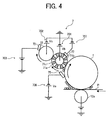
- FIG. 4 illustrates a schematic configuration of the cleaning device 7.
- the cleaning device 7 has a brush roller 71 functioning as a cleaning member, a collection roller 72 functioning as a collection member, a scraper member 73 functioning as a separation member, a transport unit, not illustrated, and a polarity control member 75 and a power supply 706 functioning together as a polarity control unit.
- the brush roller 71 has a core member 71c and numerous bristles 71a and 71b disposed on the surface of the core member 71c.
- the brush roller 71 brings the tips of the bristles 71a and 71b into contact with the photoconductor 1 and is rotated by a driving unit, not illustrated, in a clockwise direction in FIG. 4 so that, at the contact portion, the surface of the brush roller 71 moves in a direction opposite a moving direction of the surface of the photoconductor 1.
- the brush roller 71 catches the residual toner remaining on the surface of the photoconductor 1 by scraping the surface of the photoconductor 1 with the bristles 71a and 71b.
- the collection roller 72 is disposed to sandwich the brush roller 71 between it and the photoconductor 1, and is rotated by a driving unit, not illustrated, in a clockwise direction of FIG. 4 so that the surface of the collection roller 72 moves in a direction opposite the moving direction of the surface of the brush roller 71.
- the scraper member 73 has a plate shape, for example, with an edge portion thereof contacting the surface of the collection roller 72 with a certain pressure.
- the transport unit is disposed below the scraper member 73.
- the polarity control member 75 receives a bias supplied from the power supply 706 and supplies an electric charge to the residual toner remaining on the surface of the photoconductor 1 to convert the polarity of the residual toner into the polarity of the bias supplied from the power supply 706.
- a portion of the toner may receive the action of a positive polarity bias at the transfer nip, and thus be positively charged.
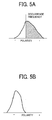
- the charging distribution of such residual toner may show a mix of negative-polarity toner and positive-polarity toner as illustrated in FIG. 5A .
- the polarity of the bias supplied from the power supply 706 is negative. Accordingly, when such residual toner in which negative-polarity toner and positive-polarity toner are mixed receives an electric charge of negative polarity from the polarity control member 75, such residual toner is uniformly charged with negative polarity as illustrated in FIG. 5B .
- the polarity control member 57 is formed of a conductive blade, the polarity control member 57 may be a brush- or film-type member capable of charging while contacting such residual toner on the surface of the photoconductor 1.
- the polarity control member 57 is brought into contact with residual toner on the surface of the photoconductor 1 to supply an electric charge to the residual toner to give it a single polarity.
- another device such as a charger, may be used to supply such electric charge to the residual toner, although the charging method described in the present exemplary embodiment is preferable because, for example, fewer discharge products which may adversely affect image formation are generated.
- the image forming apparatus 1000 may have a configuration that the residual toner is uniformized into positive polarity.
- a power supply 701 is connected to a shaft portion of the brush roller 71 to supply a positive-polarity bias to the brush roller 71.
- the uniformly charged residual toner is electrostatically attracted onto the positive-polarity brush roller 71. As a result, the residual toner can be removed from the surface of the photoconductor 1.
- a power supply 702 is connected to a shaft portion of the collection roller 72 to supply a positive-polarity bias.
- the negative-polarity toner electrostatically attracted onto the brush roller 71 is collected to the collection roller 72 by utilizing an electric potential gradient between the brush roller 71 and the collection roller 72.
- the toner collected to the collection roller 72 is mechanically scraped away from the surface of the collection roller 72 with the scraper member 73.
- Such scraped toner is transported to a waste toner bottle, not illustrated, by the transport unit. Alternatively, such scraped toner may be transported to the developing device 6 for reuse.
- a surface layer of the collection roller 72 has a volume resistivity of, for example, approximately 10 5 to 10 8 ⁇ cm, a slight amount of the residual toner on the surface of the photoconductor 1 may pass through a cleaning region at which the photoconductor 1 faces the brush roller 71, thereby resulting in a cleaning failure.
- One method of preventing such cleaning failure is to form the surface layer of the collection roller 72 with an insulation layer. According to such method, when the collection roller 72 contacts the residual toner, an electric charge is prevented from being supplied from the collection roller 72 to the residual toner, thereby preventing such cleaning failure. Accordingly, in the present exemplary embodiment, the surface layer of the collection roller 72 is formed of such insulation layer.
- the collection roller 72 has a metal core, that is, a shaft portion of metal material, and is produced by inserting the metal core into an insulation member of a hollow, circular cylindrical shape and by integrally molding the metal core and the insulation member.
- the collection roller 72 can be easily produced by covering the metal core with a tube member of PET (polyethylene terephthalate), PFA (perfluoroalkoxy resin), copolymerization nylon, or the like.
- alumite treatment or Teflon (registered trademark) hard slumite treatment is performed on an aluminum core to obtain a insulated metal surface. Then, such metal surface is coated with an inorganic material such as ceramic, or an organic material such as a PTFE (polytetrafluoroethylene), polyimide, or polycarbonate.
- an inorganic material such as ceramic, or an organic material such as a PTFE (polytetrafluoroethylene), polyimide, or polycarbonate.
- the surface layer of the collection roller 72 preferably has a thickness of not more than 1 mm, more preferably not more than 0.5 mm.
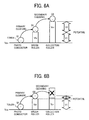
- FIGS. 6A and 6B illustrate relations between the transportation of toner from the surface of the photoconductor 1, on one hand, to the surface of the collection roller 72, the surface potential Vpc of the photoconductor 1, the surface potential Vbr of the brush roller 71, and the surface potential Vcr of the collection roller 72 on the other.
- the surface layer of the collection roller 72 is formed of an insulation layer. Toner is charged to have a negative polarity.
- Q1 represents a charge of toner on the photoconductor 1
- Q2 represents a charge of toner on the brush roller 71
- Q3 represents a charge of the collection roller 72.
- the surface potential Vpc of the photoconductor 1 is set to 0V.
- V1 electric potential difference
- V2 electric potential difference
- a decrease in the surface potential of the collection roller 72 may reduce the electric potential difference V2 between the brush roller 71 and the collection roller 72 as illustrated in FIG. 6B .
- an electrical field sufficient to shift the toner from the brush roller 71 to the collection roller 72 cannot be generated between the brush roller 71 and the collection roller 72, thereby preventing the secondary cleaning from being effectively executed.
- a power supply 703 is connected to the scraper member 73 to supply electric charge of a polarity opposite that of the toner, which is the cleaning target of the brush roller 71.
- the power supply 703 supplies, through the scraper member 73 to the surface of the collection roller 72, a bias of approximately 400V to 800V higher than the bias supplied to the shaft portion of the collection roller 72.
- a bias of approximately 400V to 800V higher than the bias supplied to the shaft portion of the collection roller 72 may be used to supply an electric charge to the surface of the collection roller 72 instead of the scraper member 73.
- an electrode member 77 is connected to a power supply 707 and contacted against the surface of the brush roller 71 as illustrated in FIG. 4 , thereby allowing an electric charge of the polarity opposite the polarity of the toner to be supplied to the surface of the brush roller 71.
- the power supply 707 supplies, through the electrode member 77 to the surface of the brush roller 71, a bias of approximately 200V to 500V higher than the bias supplied to the shaft portion of the brush roller 71.
- a bias of approximately 200V to 500V higher than the bias supplied to the shaft portion of the brush roller 71 may be used to supply electric charge to the surface of the collection roller 72 instead of the scraper member 73.
- FIG. 7 is a graph illustrating a relation between the voltage applied to the scraper member 73 and the surface potential of the collection roller 72. This graph also illustrates a relation between the surface potential of the brush roller 71 and each of the voltage applied to the scraper member 73 and the surface potential of the collection roller 72.
- the graph of FIG. 7 illustrates changes over time in the surface potential of the collection roller 72 when the voltage applied to the scraper member 73 is changed between 1000V, 1500V, and 2000V.
- the voltage applied to the brush roller 71 is set to 700V
- the voltage applied to the collection roller 72 is set to 1000V.
- the graph of FIG. 7 indicates that with a relatively low voltage applied to the scraper member 73 the surface potential of the collection roller 72 decreases over time. As a result, the difference in surface potential between the collection roller 72 and the brush roller 71 decreases, thereby preventing the toner on the brush roller 71 from shifting to the collection roller 72.
- applying a sufficiently high voltage of, for example, approximately 2000V can prevent the surface potential of the collection roller 72 from decreasing.
- a sufficiently high voltage of, for example, approximately 2000V can prevent the surface potential of the collection roller 72 from decreasing.
- the difference in surface potential between the collection roller 72 and the brush roller 71 can be prevented from decreasing over time, thereby maintaining the collection efficiency of toner by the collection roller 72 at a preferable level over time.
- the scraper member 73 performs the functions of separating or scraping toner from the surface of the collection roller 72 and supplying an electric charge to the surface of the collection roller 72.
- the scraper member 73 is formed of an elastomer material, for example, polyurethane, silicone, or nitrile rubber, capable of obtaining a desired adherence to the surface of the collection roller 72.
- such elastomer material preferably has a volume resistivity of, for example, not more than 10 12 ⁇ cm.
- One method of obtaining such volume resistivity is to add carbon, filler metal, and/or ion conductive agent to the above-described elastomer material.
- the scraper member 73 needs to be appropriately contacted against the surface of the collection roller 72.
- FIG. 8 is a schematic view illustrating the scraper member 73 contacting the surface of the collection roller 72 according to the counter manner, viewed from an axial direction of the collection roller 72.
- FIG. 9 is an enlarged view of a portion indicated by "A” in FIG. 8 when the scraper member 73 presses against the collection roller 72.
- the portion "A” is a contact portion between the scraper member 73 and the collection roller 72.
- FIG. 10 illustrates pressure vectors of the scraper member 73 in the state of FIG. 9 .
- FIG. 11 is an enlarged view of the portion "A" in FIG. 8 when the scraper member 73 is not in contact with the collection roller 72.
- FIG. 12 illustrates pressure vectors of the scraper member 73 in the state of FIG. 11 .
- FIG. 9 illustrates a deformed state of the scraper member 73 having a blade thickness "t" of not more than 2.2 mm.
- FIG. 11 illustrates a deformed state of the scraper member 73 having a blade thickness "t" of more than 2.2 mm.
- the scraper member 73 is pressed against the surface of the collection roller 72 with an identical pressure.
- the linear pressure applied to the scraper member 73 is the same in either of the states.
- the term "linear pressure” used herein refers to a value obtained by dividing the pressure applied to the scraper member 73 by the length of the scraper member 73 in the axial direction of the collection roller 72 at the contact portion between the scraper member 73 and the collection roller 72.
- FIG. 11 is a state at which only an edge face of the scraper member 73 contacts the surface of the collection roller 72.
- Increasing the linear pressure to be applied to the scraper member 73 may result in an increase in the deformation amount of the collection roller 72.
- the collection roller 72 since the collection roller 72 receives a weight from the scraper member 73 in a substantially horizontal direction, a middle portion of the collection roller 72 in its axial direction is considerably deformed.
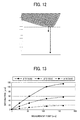
- FIG. 13 is a graph showing the deformation amount of the collection roller 71 observed when the scraper member 73 is pressed against the collection roller 72 having a length of 320 mm in its axial direction with a linear pressure of 50 g/cm.
- the deformation amount of the collection roller 72 is symmetrical with respect to the middle portion in the axial direction of the collection roller 72, the deformation amount of only half the collection roller 72 is shown in FIG. 11 .
- the vertical axis represents the deformation amount of the collection roller 72
- the horizontal axis represents a distance from one end of the collection roller 72 to a measurement point.
- the metal core of the collection roller 72 is made of SUS (stainless used steel).
- This graph indicates that, when the roller diameter of the collection roller 72 is not more than 10 mm, the maximum deformation amount of the collection roller 72 is more than 0.1 mm. Consequently, a difference in the cleaning performance of the scraper member 73 may be generated between the middle portion and each end portion of the collection roller 72 in its axial direction.
- the relation between the linear pressure of the scraper member 73 and the diameter of the collection roller 72 is adjusted so that the deformation amount of the collection roller 72 may be not more than 0.1 mm.
- the surface of the collection roller 72 may be degraded due to the scraping of the scraper member 73 and the discharge generated during the supply of such electric charge.
- the surface of the collection roller 72 may be degraded faster than the case where an electric charge is not supplied in such manner, thereby causing the surface of the collection roller 72 to be more easily roughened over time. Consequently, the friction coefficient between the surface of the collection roller 72 and the scraper member 73 may be reduced over time, thereby undesirably causing toner to more easily pass through the contact portion between the surface of the collection roller 72 and the scraper member 73 over time.
- FIG. 14 is a schematic view illustrating a state of the contact portion between the surface of the collection roller 72 and the scraper member 73 at an initial stage.
- FIG. 15 is a schematic view illustrating a state of the contact portion between the surface of the collection roller 72 and the scraper member 73 at a given later stage sometime after the initial stage.
- the surface of the collection roller 72 is not rough at the initial stage.
- the surface of the collection roller 72 is roughened due to the scraping of the scraper member 73 and the discharge during the supply of electric charge through the scraper member 73.
- Such increasing roughness of the surface of the collection roller 72 may reduce the friction coefficient ⁇ between the surface of the collection roller 72 and the scraper member 73 ( ⁇ 1> ⁇ 2), and also reduces the friction force F therebetween (F1>F2). As a result, a portion of the toner on the surface of the collection roller 72 may go under the contact surface of the scraper member 73 and then pass through the contacting portion between the surface of the collection roller 72 and the scraper member 73.
- Such passing toner is carried to another contact portion between the surface of the collection roller 72 and the brush roller 71 by the rotation of the collection roller 72.
- Such passing toner receives an electric charge, which may reverse the polarity of such passing toner to positive polarity.
- Such reversely-charged toner is shifted to the brush roller 71 at the second contact portion.
- such reversely-charged toner may be shifted to the surface of the photoconductor 1 and then adhered to the surface of the photoconductor 1 as residual toner after cleaning.
- the roughness Ra of the surface of the collection roller 72 needs to be relatively low and also be maintained relatively low over time. In other words, the surface of the collection roller 72 needs to have a relatively high resistance to the scraping and discharge described above.
- FIG. 16 is a graph showing relations between surface roughness Ra and cleaning performance in various rollers usable as the collection roller 72.
- the vertical axis represents scores of the cleaning performance of each roller, that is, measurement results of image density (ID) obtained by transferring residual toner, remaining on the surface of the collection roller 72 after passing the contact portion with the scraper member 73, to a tape member and then by attaching the tape to a sheet.
- the horizontal axis represents the surface roughness Ra of each roller.
- a low score of the image density indicates a small amount of such residual toner, that is, a preferable cleaning performance. For example, scores of not more than 0.02 can prevent a cleaning failure from being generated.
- the surface roughness Ra in FIG. 16 was measured by using a SURFCOM 590A surface roughness meter from Tokyo Seimitsu Co., Ltd.
- steel-wool scratch test is conducted by using a reciprocating abrasion resistance measurement device such as HEIDON TRIBOGEAR manufactured by Shinto Scientific Co., Ltd.
- the test conditions may be like those described below, for example.
- a steel-wool pad has a size of 2 cm X 2 cm, that is, a contact area of 4 cm 2 .
- As the steel wool for example, BONSTAR #0000 manufactured by Nihon Steel Wool Co., Ltd. is used.
- the surface roughness Ra was measured at an initial stage, and then the steel-wool scratch test was conducted. Further, the cleaning performance was evaluated at both the initial and later stages.
- TABLE 2 shows evaluation results of the cleaning performance of the 15 types of collection rollers.
- the "later stage” used herein refers to a time after 150,000 sheets (on A4-size basis) pass through the transfer nip.
- [Table 2] TYPE OF SURFACE MATERIAL SURFACE ROUGHNESS Ra SCRATCH TEST CLEANING PERFORMANCE RANK INITIAL LATER 1 0.522333 A 0.075 0.07 2 0.511333 D 0.07 0.2 3 0.471333 D 0.06 0.15 4 0.441 A 0.08 0.1 5 0.342667 D 0.05 0.09 6 0.259 D 0.04 0.13 7 0.232 D 0.04 0.166 8 0.226333 D 0.035 0.06 9 0.213 B 0.05 0.023 10 0.101667 C 0.019 0.03 11 0.079333 B 0.014 0.01 12 0.05 A 0.001 0.002 13 0.042667 A 0.003 0.001 14 0.030333 B 0.002 0.001 15 0.03 D 0.00
- each of the 10th and 15th collection rollers showed a considerably low surface roughness Ra at the initial stage and a poor cleaning performance at the later stage.
- the 10th and 15th collection rollers showed ranks below B (rank C and rank D, respectively).
- each of the 11th to 14th collection rollers showed a considerably low surface roughness Ra at the initial stage and an excellent cleaning performance of not more than 0.02 at the later stage.
- the 11th to 14th collection rollers showed ranks of B or higher (rank A and rank B.
- the photoconductor 1 has a basic structure that includes a conductive support body, a latent image bearing layer, and a surface layer (protective layer).
- the latent image bearing layer should be chargeable and electrically insulating.
- a non-photoconductive dielectric layer or a photoconductive photosensitive layer may be used as the latent image bearing layer.
- the protective layer of the photoconductor 1 may be preferably formed of a binder resin having a cross-linked structure. Further, a charge transport portion may be provided in the cross-linked structure of such binder resin, thereby enhancing its durability.
- Such cross-linked structure of the binder resin is formed by using, for example, light or heat energy, a cross-linking reaction is generated in a reactive monomer having a plurality of cross-linking functional groups per molecule, thereby producing a three-dimensional mesh structure.
- Such mesh structure functions as the binder resin, and provides a relatively high abrasion resistance.
- all or a portion of the above-mentioned reactive monomer preferably has the transportability of an electric charge.
- a charge transport portion can be formed inside the mesh structure, thereby providing excellent protection performance.
- Such reactive monomer having charge transportability is, for example, a compound containing at least one charge transportable component and at least one silicon atom hydrolyzable substituent per molecule, a compound containing a charge transportable component and a hydroxyl group per molecule, a compound containing a charge transportable component and a carboxyl group per molecule, a compound containing a charge transportable component and an epoxy group per molecule, and a compound containing a charge transportable component and an isocyanate group per molecule.
- Such charge transportable materials having these reactive groups may be used either alone or in combination of two or more materials thereof. More preferably, such reactive monomer having charge transportability may have a triarylamine structure because of high electrical and chemical stabilities and high carrier mobility.
- a polymerizable monomer and a polymerizable oligomer may be combined to adjust its viscosity during coating, reduce the stress of the cross-linked charge transport layer, and/or reduce the surface energy and friction coefficient.
- known polymerizable monomer and oligomer may be used as such polymerizable monomer and oligomer.
- polymerization or cross linking of a hole transporting compound may be conducted with heat or light.
- the polymerization reaction may be initiated by heat only.
- an additional polymerization initiating agent may need to start the polymerization reaction.
- such polymerization initiating agent is preferably used.
- the polymerization reaction with light for example, preferably an ultraviolet light is used.
- a light-polymerization initiating agent is typically used.
- the light-polymerization initiating agent used herein primarily absorbs ultraviolet rays having wavelengths of not more than 400 nm to generate radicals, ions, or other active species, thereby initiating a polymerization reaction.
- the heat-polymerization initiating agent and the light-polymerization initiating agent described above may be used together.
- the charge transport layer having such mesh structure has a high abrasion resistance, while may be subjected to a considerable decrease in volume contraction during cross-linking reaction. Consequently, an increase in the thickness of the charge transport layer may generate cracks in the charge transport layer.
- the protective layer may have a lamination structure including, for example, a lower protective sub-layer made of a low-molecular-weight dispersion polymer on the photosensitive layer side and an upper protective sub-layer having a cross-linked structure on the surface side.
- the photoconductor 1 may be produced with a coating liquid for the protective layer, a layer thickness.
- the production conditions are as follows.
- methyl trimethoxysilane 182 parts of methyl trimethoxysilane, 40 parts of dihydroxymethyl triphenylamine, 225 parts of 2-propanol, 225 parts of 2% acetic acid, one part of aluminum tris acetylacetonate are mixed to prepare the coating liquid for the protective layer.
- the coating liquid is coated and dried on the charge transport layer, and then hardened by heat treatment under a temperature of 110°C for one hour to form a protective layer of approximately 3 ⁇ m.
- a coating material for the surface protective layer is prepared and applied onto the charge transport layer according to a spray coating method.
- the coating material is hardened with a light intensity of 500 mW/cm 2 for 30 seconds by using a metal halide lamp to form a surface protective layer having a thickness of 5 ⁇ m.
- the toner has a shape factor SF1 of 100 to 150.
- FIG. 17 is an illustration for explaining a method of calculating such shape factor SF1.
- FIG. 18 is an illustration for explaining a method of calculating a shape factor SF2.
- the shape factor SF1 is a numeral value indicating the degree of roundness in the shape of a round material and is expressed by the following Equation 1.
- SF ⁇ 1 ( MXLNG ⁇ ) 2 / AREA ⁇ 100 ⁇ ⁇ / 4
- MXLNG represents a maximum length of an elliptical figure obtained by projecting such round material onto a two-dimensional plane
- AREA represents an area of the elliptical figure.
- the shape factor SF2 is a numerical value indicating the degree of irregularity in the shape of a material and is expressed by the following Equation 2.
- SF ⁇ 2 ( PELI ⁇ ) 2 / AREA ⁇ 100 ⁇ ⁇ / 4
- PELI represents a circumferential length of a figure obtained by projecting the material onto a two-dimensional plane
- AREA represents an area of the figure.
- toner images are randomly sampled 100 times with FE-SEM (S-800) manufactured by HITACHI, Ltd, for example.
- the sampled images are input to and analyzed by LUZEX III image analyzer manufactured by Nikon Corporation, for example.
- the shape factor SF2 is calculated by using the above Equation 2.
- Example 1 an example (hereinafter, “Example 1") of the cleaning device 7 is described.
- the collection roller 72 has a metal core made of SUS having a diameter of 16 mm.
- the metal core is coated with a tube, such as a PVDF (poly vinyledene fluoride) tube manufactured by Okura Industrial Co., Ltd., having a thickness of 0.1 mm. Further, the tube is dipping-coated with an acrylic UV resin to produce the collection roller 72.
- a tube such as a PVDF (poly vinyledene fluoride) tube manufactured by Okura Industrial Co., Ltd.
- the surface layer of acrylic UV resin has a thickness of 5 ⁇ m and corresponds to the 13th surface material shown in Table 2.
- the surface layer Ra is 0.042667 ⁇ m
- the evaluation result of surface hardness in the steel-wool scratch test is rank "A”.
- the scraper member 73 having a blade thickness of 2.4 mm, a JIS-A hardness of 70°, and a free length L of 7 mm is pressed against the collection roller 72 with a linear pressure of 70 gf/cm, the deformation amount of the middle portion of the collection roller 72 was 0.01 mm.
- the supply voltage Vbr which the power supply 701 supplies to the shaft portion of the brush roller 71 is 300V.
- the supply voltage Vbs which the power supply 707 supplies to the surface of the brush roller 71 is 300V.
- the supply voltage Vcr which the power supply 702 supplies to the shaft portion of the collection roller 72 is 800V.
- the supply voltage Vcs which the power supply 703 supplies to the surface of the scraper member 73 is 2000V.
- the linear velocities of the photoconductor 1, the brush roller 71, and the collection roller 72 are 200 mm/s, 100 to 300 mm/s, and 100 to 300 mm/s, respectively.
- the brush roller 71 rotates in a counter direction with respect to the photoconductor 1
- the collection roller 72 rotates in a counter direction with respect to the brush roller 71.
- Example 1 when the above-described cleaning performance of the cleaning device 7 was tested, an excellent cleaning performance of not more than 0.02 was maintained in any environment of a high-temperature, high-humidity environment of 32°C and 80% RH (relative humidity) and a high-temperature, high-humidity environment of 10°C and 15% RH. Further, such results of cleaning performance were maintained over time.
- Example 2 Another example (hereinafter, “Example 2") of the cleaning device 7 is described.
- the collection roller 72 has the following configuration. That is, the collection roller 72 includes a metal core having a diameter of 16 mm and made of SUS. The surface of the metal core is fired with, for example, an inorganic ceramics of Atom Compobrid CSS-H produced by Atomix Co., Ltd., under a temperature of 120°C for 30 minutes. Thus, a fine, robust matrix of inorganic siloxane is formed on the surface of the metal core.
- the surface layer thus obtained has a thickness of 10 ⁇ m and corresponds to the 12th surface material of Table 2.
- the surface roughness Ra is 0.05 ⁇ m
- the evaluation result of surface hardness in the steel-wool scratch test is rank "A”.
- the scraper member 73 having a blade thickness of 2.4 mm, a JIS-A hardness of 70°, and a free length L of 7 mm was contacted with the surface of the collection roller 72 with a linear pressure of 70 gf/cm, the deformation amount of a middle portion of the collection roller 72 was 0.018 mm.
- the supply voltage Vbr which the power supply 701 supplies to the shaft portion of the brush roller 71 is 300V.
- the supply voltage Vbs which the power supply 707 supplies to the surface of the brush roller 71 is 300V.
- the supply voltage Vcr which the power supply 702 supplies to the shaft portion of the collection roller 72 is 800V.
- the supply voltage Vcs which the power supply 703 supplies to the surface of the scraper member 73 is 2000V.
- the linear velocities of a photoconductor 1, the brush roller 71, and the collection roller 72 are 200 mm/s, 100 to 300 mm/s, and 100 to 300 mm/s, respectively.
- the brush roller 71 rotates in a counter direction with respect to the photoconductor 1
- the collection roller 72 rotates in a counter direction with respect to the brush roller 71.
- Example 2 when the above-described cleaning performance of the cleaning device 7 was tested, an excellent cleaning performance of not more than 0.02 was maintained in any environment of a high-temperature, high-humidity environment of 32°C and 80% RH (relative humidity) and a high-temperature, high-humidity environment of 10°C and 15% RH. Further, such result of cleaning performance was maintained over time.
- Variation Example 1 a variation example (hereinafter, Variation Example 1) of the cleaning device 7 is described.
- FIG. 19 illustrates a schematic configuration of Variation Example 1 of the cleaning device 7.
- the cleaning device 7 is provided with an electrode member 78 independently of the scraper member 73.
- a power supply 708 is connected to the electrode member 78 to charge the surface of the collection roller 72.
- the electrode member 78 independent of the scraper member 73 charges the surface of the collection roller 72, while the scraper member 73 does not charge the surface of the collection roller 72.
- electric discharge is not induced between the scraper member 73 and the surface of the collection roller 72.
- the contact portion of the scraper member 73 between it and the surface of the collection roller 72 is prevented from being degraded due to such discharge, thereby allowing preferable cleaning performance of the scraper member 73 to be maintained over time.
- the electrode member 78 may be made of, for example, a SUS material, a conductive resin material, or a conductive rubber roller material having a diameter of 6 to 10 mm.
- FIG. 20 illustrates a schematic configuration of Variation Example 2 of the cleaning device 7.
- the surfaces of the brush roller 71 and the collection roller 72 are charged with a single electrode member 79.
- the electrode member 79 is disposed at the vicinity of the contact portion between the brush roller 71 and the collection roller 72 so as to contact both surfaces of the brush roller 71 and the collection roller 72.
- the electrode member 79 has an insulating member and a conductive member, such as a phosphorus bronze plate or a stainless plate, which is laid on the insulating member.
- the insulating member and the conductive member are connected to the power supplies 707 and 708, respectively, thereby reducing the number of components.
- the cleaning device 7 is applicable to an image forming apparatus employing an image bearing member having another shape.
- the cleaning device 7 is similarly applicable to an image forming apparatus including a belt-shaped photoconductor in which a belt is extended over two rollers so as to endlessly move.
- the charge potential of the photoconductor 1 is negative and the developing device employs the reverse development method using the two-component developer. It should be noted that the charge potential of such photoconductor is not limited to negative polarity and may have positive polarity. Alternatively, such developing device may employ a single component developer or may be a normal development method.
- the cleaning device is applied to the monochrome image forming apparatus having a single process cartridge, the cleaning device is applicable to other types of image forming apparatus.
- such cleaning device is applicable to a color image forming apparatus having a tandem-type image forming section in which four process cartridges 100Y, 100C, 100M, and 100K are arranged in tandem as illustrated in FIG. 21 .
- the cleaning device is applicable to an image forming apparatus employing an intermediate transfer method in which a toner image on a photoconductor is transferred onto an intermediate transfer member, and then the toner image on the intermediate transfer member is transferred onto a transfer sheet.
- the cleaning device may be used as any of a cleaning device that removes residual toner remaining on the intermediate transfer belt after the transfer process and a cleaning device for the intermediate transfer belt that removes residual toner remaining on the intermediate transfer belt.
- Such intermediate transfer body may have a belt shape or a drum shape.
- the electrical characteristic such as volume resistivity or surface resistivity, thickness, structure such as single-, dual-, three or more layer, material of such intermediate transfer body may be appropriately selected according to imaging conditions.
- the cleaning device 7 has the brush roller 71, the collection roller 72, the power supplies 701, 702, 703, 707, and 708, and the scraper member 73.
- the brush roller 71 functions as a cleaning member that removes toner of a predetermined polarity (negative polarity in the above description) remaining on the surface of the photoconductor by moving its surface so as to contact the surface of the photoconductor, which is the target of the cleaning operation.
- the collection roller 72 functions as the collection member that collects toner adhered to the surface of the brush roller 71 by moving its surface so as to contact the surface of the brush roller 71.
- Each of the power supplies 701, 702, 703, 707, and 708 functions as the electrical field generator that generates an electrical field to shift toner on the brush roller 71 to the collection roller 72 at the contact portion between the brush roller 71 and the collection roller 72.
- the scraper member 73 is disposed to press against the surface of the collection roller 72 so as to function as a separation member that separates toner adhered to the surface of the collection roller 72 from the surface of the collection roller 72.
- the centerline average surface roughness Ra is not more than 0.1 ⁇ m, and the evaluation result of its surface hardness by the steel-wool scratch test is rank B or higher.
- Such configuration allows the friction coefficient between the surface of the collection roller 72 and the scraper member 73 to be maintained relatively high over time, thereby preventing a cleaning failure from occurring on the surface of the collection roller 72 in the long term.
- the surface layer of the collection roller 72 is made of an insulating layer
- the cleaning device 7 has an electric-charge supply unit that charges the surface of the collection roller 72 by applying, to the scraper member 73, a bias having a polarity opposite the predetermined polarity (here, negative polarity).
- a bias having a polarity opposite the predetermined polarity here, negative polarity.
- Such configuration can prevent such a failure as a reduction over time of the surface potential of the collection roller 72 due to the configuration that the surface of the collection roller 72 is made of the insulating layer.
- an electric charge is supplied using the scraper member 73, thereby reducing the number of components compared to the case where the cleaning device 7 has a specific member for supplying an electric charge to the surface of the collection roller 72.
- the surface layer of the collection roller 72 has a thickness of not more than 1 mm. Accordingly, the surface layer is relatively stable with respect to an environmental change under a typical use condition.
- the scraper member 73 is made of an elastomer material and is configured as a blade member having a volume resistivity of not more than 10 12 ⁇ cm. Such configuration provides excellent adherence between the scraper member 73 and the surface of the collection roller 72, thereby providing preferable cleaning performance. Such configuration also allows an electric charge to be supplied to the surface of the collection roller 72 using the scraper member 73.
- the scraper member 73 is formed of a blade member having a thickness of more than 2.2 mm.
- the scraper member 73 is pressed against the surface of the collection roller 72 with a linear pressure of more than 50 gf/cm.
- Such configuration can prevent the scraper member 73 from contacting the surface of the collection roller 72 at the so-called "belly contact state" described above.
- the scraper member 73 can maintain a preferable contact state between it and the surface of the scraper member 73, thereby providing excellent cleaning performance.
- the cleaning device 7 is configured so that the deformation amount of the collection roller 72 due to the contact between it and the scraper member 73 be not more than 0.1 mm. Such configuration can prevent a variation from occurring in the cleaning performance in the axial direction of the collection roller 72.
Landscapes
- Physics & Mathematics (AREA)
- General Physics & Mathematics (AREA)
- Cleaning In Electrography (AREA)
- Developing Agents For Electrophotography (AREA)
- Photoreceptors In Electrophotography (AREA)
Applications Claiming Priority (1)
| Application Number | Priority Date | Filing Date | Title |
|---|---|---|---|
| JP2007155716A JP2008309902A (ja) | 2007-06-12 | 2007-06-12 | クリーニング装置、並びに、これを備えた画像形成装置及びプロセスカートリッジ |
Publications (2)
| Publication Number | Publication Date |
|---|---|
| EP2003518A2 true EP2003518A2 (de) | 2008-12-17 |
| EP2003518A3 EP2003518A3 (de) | 2009-02-11 |
Family
ID=39680938
Family Applications (1)
| Application Number | Title | Priority Date | Filing Date |
|---|---|---|---|
| EP08158118A Withdrawn EP2003518A3 (de) | 2007-06-12 | 2008-06-12 | Reinigungsvorrichtung, Bilderzeugungsvorrichtung damit und Vorgangskartusche mit der Vorrichtung |
Country Status (3)
| Country | Link |
|---|---|
| US (1) | US8280295B2 (de) |
| EP (1) | EP2003518A3 (de) |
| JP (1) | JP2008309902A (de) |
Families Citing this family (22)
| Publication number | Priority date | Publication date | Assignee | Title |
|---|---|---|---|---|
| JP2010014943A (ja) * | 2008-07-03 | 2010-01-21 | Ricoh Co Ltd | クリーニング装置、画像形成装置、プロセスカートリッジ |
| JP2010020026A (ja) * | 2008-07-09 | 2010-01-28 | Ricoh Co Ltd | クリーニング装置および画像形成装置 |
| JP2010044123A (ja) * | 2008-08-08 | 2010-02-25 | Ricoh Co Ltd | 極性制御装置、クリーニング装置、画像形成装置、多色画像形成装置およびプロセスカ−トリッジ |
| JP5305154B2 (ja) * | 2008-11-21 | 2013-10-02 | 株式会社リコー | 画像形成装置 |
| US8273511B2 (en) | 2008-12-25 | 2012-09-25 | Fuji Xerox Co., Ltd. | Electrophotographic photoreceptor, manufacturing method of electrophotographic photoreceptor, processing cartridge, and image forming apparatus |
| JP4702448B2 (ja) * | 2008-12-26 | 2011-06-15 | 富士ゼロックス株式会社 | 電子写真感光体及びその製造方法、プロセスカートリッジ、並びに画像形成装置。 |
| JP5538765B2 (ja) | 2009-07-23 | 2014-07-02 | 株式会社ジャパンディスプレイ | 液晶表示装置 |
| JP2011102958A (ja) * | 2009-10-13 | 2011-05-26 | Ricoh Co Ltd | クリーニング装置及び画像形成装置 |
| JP5464487B2 (ja) * | 2010-03-18 | 2014-04-09 | 株式会社リコー | クリーニング装置および画像形成装置 |
| JP5641407B2 (ja) | 2010-08-09 | 2014-12-17 | 株式会社リコー | クリーニング装置及び画像形成装置 |
| US8712267B2 (en) | 2011-03-18 | 2014-04-29 | Ricoh Company, Ltd. | Image forming apparatus and image forming method |
| JP6209312B2 (ja) | 2011-03-18 | 2017-10-04 | 株式会社リコー | 画像形成装置及び画像形成方法 |
| JP5900794B2 (ja) | 2011-06-22 | 2016-04-06 | 株式会社リコー | 画像形成装置 |
| JP6106974B2 (ja) | 2011-11-14 | 2017-04-05 | 株式会社リコー | 転写装置及び画像形成装置 |
| JP2014048536A (ja) | 2012-08-31 | 2014-03-17 | Ricoh Co Ltd | クリーニング装置、画像形成装置及び電圧設定装置 |
| JP2014224960A (ja) | 2013-01-10 | 2014-12-04 | 株式会社リコー | クリーニング装置、プロセスカートリッジ、及び画像形成装置 |
| US9395658B2 (en) | 2014-12-09 | 2016-07-19 | Ricoh Company, Ltd. | Image forming apparatus |
| US9817341B2 (en) | 2015-03-18 | 2017-11-14 | Ricoh Company, Ltd. | Image forming apparatus |
| JP2016177044A (ja) | 2015-03-19 | 2016-10-06 | 株式会社リコー | 画像形成装置 |
| CN109416520B (zh) | 2016-07-20 | 2021-08-10 | 惠普印迪格公司 | 操作液体电子照相打印机 |
| JP6589901B2 (ja) * | 2017-01-31 | 2019-10-16 | 京セラドキュメントソリューションズ株式会社 | クリーニング装置及び画像形成装置 |
| JP6862924B2 (ja) * | 2017-03-02 | 2021-04-21 | セイコーエプソン株式会社 | 制御装置、受電装置及び電子機器 |
Citations (7)
| Publication number | Priority date | Publication date | Assignee | Title |
|---|---|---|---|---|
| US4469435A (en) | 1981-10-28 | 1984-09-04 | Tokyo Shibaura Denki Kabushiki Kaisha | Combination charging/cleaning arrangement for copier |
| US5212530A (en) | 1990-11-30 | 1993-05-18 | Hitachi Koki Co., Ltd. | Cleaning unit for a xerographic printing machine |
| US20010018003A1 (en) | 2000-02-24 | 2001-08-30 | William Waterschoot | Cleaning device |
| US20030031489A1 (en) | 2001-07-24 | 2003-02-13 | Nexpress Solutions Llc | Cleaning brush for electrostatographic imaging apparatus and apparatus containing same |
| JP2005275085A (ja) * | 2004-03-25 | 2005-10-06 | Fuji Xerox Co Ltd | クリーニング装置 |
| JP2007057829A (ja) * | 2005-08-24 | 2007-03-08 | Fuji Xerox Co Ltd | クリーニング装置および画像形成装置 |
| JP2007101683A (ja) | 2005-09-30 | 2007-04-19 | Fuji Xerox Co Ltd | クリーニング装置及びこれを用いた画像形成装置 |
Family Cites Families (42)
| Publication number | Priority date | Publication date | Assignee | Title |
|---|---|---|---|---|
| US4634647A (en) * | 1983-08-19 | 1987-01-06 | Xerox Corporation | Electrophotographic devices containing compensated amorphous silicon compositions |
| JPH0242230A (ja) | 1988-08-02 | 1990-02-13 | Bando Chem Ind Ltd | 歯付ベルト |
| JPH07219348A (ja) * | 1993-12-07 | 1995-08-18 | Ricoh Co Ltd | 電子写真装置 |
| JP3439273B2 (ja) * | 1994-01-19 | 2003-08-25 | 株式会社リコー | 電子写真装置 |
| US5514508A (en) * | 1994-05-31 | 1996-05-07 | Mita Industrial Co., Ltd. | Electrophotosensitive material |
| US5606408A (en) * | 1994-09-30 | 1997-02-25 | Ricoh Company, Ltd. | Image forming apparatus and cleaning device therefor |
| JP3243135B2 (ja) * | 1995-02-02 | 2002-01-07 | 株式会社リコー | 画像形成装置 |
| JPH0854814A (ja) | 1995-07-13 | 1996-02-27 | Ricoh Co Ltd | クリーニング装置 |
| US5740494A (en) * | 1995-08-20 | 1998-04-14 | Ricoh Company, Ltd. | Configured to enhance toner collecting efficiency and toner redepositing efficiency |
| JP3598178B2 (ja) * | 1995-12-28 | 2004-12-08 | 株式会社リコー | カラー画像形成方法 |
| JPH1069196A (ja) | 1996-08-28 | 1998-03-10 | Nec Corp | 画像形成装置 |
| US5999773A (en) * | 1997-06-12 | 1999-12-07 | Ricoh Company, Ltd. | Image forming apparatus and cleaning method for contact-charging member |
| JP2000155512A (ja) * | 1998-11-20 | 2000-06-06 | Toyo Tire & Rubber Co Ltd | 帯電防止型クリーニングブレード |
| JP3889891B2 (ja) * | 1999-01-21 | 2007-03-07 | 北辰工業株式会社 | ブレード |
| JP2001296694A (ja) * | 2000-04-13 | 2001-10-26 | Konica Corp | 画像形成方法、及び画像形成装置 |
| US6640080B2 (en) * | 2000-12-26 | 2003-10-28 | Konica Corporation | Image forming apparatus and image forming method |
| US6987944B2 (en) * | 2001-03-28 | 2006-01-17 | Ricoh Company, Ltd. | Cleaning device and image forming apparatus using the cleaning device |
| JP4907782B2 (ja) * | 2001-05-18 | 2012-04-04 | 株式会社リコー | クリーニング装置及びそのクリーニング装置を具備する画像形成装置 |
| JP2003057913A (ja) | 2001-08-21 | 2003-02-28 | Pfu Ltd | 液体現像電子写真装置 |
| JP2004053893A (ja) | 2002-07-19 | 2004-02-19 | Fuji Xerox Co Ltd | 像担持体表面クリーニングユニット、それを用いた像担持体表面クリーニング装置、プロセスカートリッジ及び画像形成装置 |
| JP4118103B2 (ja) * | 2002-08-27 | 2008-07-16 | 株式会社沖データ | 画像形成装置 |
| US7123872B2 (en) * | 2002-09-11 | 2006-10-17 | Ricoh Company, Ltd. | Cleaning device and method, image forming apparatus, and process cartridge |
| JP2004184863A (ja) | 2002-12-05 | 2004-07-02 | Fuji Xerox Co Ltd | 画像形成装置 |
| US7103301B2 (en) * | 2003-02-18 | 2006-09-05 | Ricoh Company, Ltd. | Image forming apparatus using a contact or a proximity type of charging system including a protection substance on a moveable body to be charged |
| US7415236B2 (en) * | 2003-04-07 | 2008-08-19 | Ricoh Company, Ltd. | Cleaning unit, process cartridge, and image-forming apparatus |
| US7062212B2 (en) * | 2003-04-17 | 2006-06-13 | Ricoh Company, Ltd. | Cleaning apparatus, image forming apparatus, and process cartridge |
| JP2005017764A (ja) | 2003-06-26 | 2005-01-20 | Fuji Xerox Co Ltd | 導電部材、像担持体クリーニングユニット、プロセスカートリッジ及び画像形成装置 |
| US20050058474A1 (en) * | 2003-09-17 | 2005-03-17 | Kazuhiko Watanabe | Cleaning device, process cartridge, and image forming apparatus |
| JP4509519B2 (ja) * | 2003-09-22 | 2010-07-21 | 株式会社リコー | クリーニング装置、プロセスカートリッジ、画像形成装置 |
| US7209699B2 (en) * | 2004-02-16 | 2007-04-24 | Ricoh Company, Limited | Lubricant applying unit, process cartridge, image forming apparatus, and image forming method |
| JP2005265907A (ja) | 2004-03-16 | 2005-09-29 | Fuji Xerox Co Ltd | クリーニング装置 |
| US7369807B2 (en) * | 2004-05-11 | 2008-05-06 | Ricoh Company, Limited | Cleaner, and process cartridge and image forming apparatus using the cleaner |
| JP2006259661A (ja) * | 2004-10-27 | 2006-09-28 | Ricoh Co Ltd | 潤滑剤供給装置および画像形成装置 |
| JP4772416B2 (ja) * | 2004-11-01 | 2011-09-14 | 株式会社リコー | クリーニング装置、プロセスカートリッジ、および画像形成装置 |
| JP5261863B2 (ja) * | 2005-06-20 | 2013-08-14 | 株式会社リコー | 画像形成装置、プロセスカートリッジ及び潤滑剤ブロック |
| JP4947938B2 (ja) * | 2005-06-20 | 2012-06-06 | 株式会社リコー | クリーニング装置、プロセスユニット、及び画像形成装置 |
| JP2007004065A (ja) * | 2005-06-27 | 2007-01-11 | Ricoh Co Ltd | 画像形成装置 |
| JP2007065580A (ja) * | 2005-09-02 | 2007-03-15 | Fuji Xerox Co Ltd | 画像形成装置 |
| JP2007132999A (ja) * | 2005-11-08 | 2007-05-31 | Ricoh Co Ltd | クリーニング装置、プロセスカートリッジ及びクリーニング装置を備えた画像形成装置 |
| JP2007248525A (ja) * | 2006-03-13 | 2007-09-27 | Ricoh Co Ltd | クリーニング装置、並びにこれを備えるプロセスユニット及び画像形成装置 |
| JP4928973B2 (ja) * | 2007-02-14 | 2012-05-09 | 株式会社リコー | クリーニング装置、プロセスカートリッジ及び画像形成装置 |
| US8036561B2 (en) * | 2008-03-10 | 2011-10-11 | Xerox Corporation | Method and apparatus for cleaning |
-
2007
- 2007-06-12 JP JP2007155716A patent/JP2008309902A/ja active Pending
-
2008
- 2008-06-11 US US12/137,158 patent/US8280295B2/en not_active Expired - Fee Related
- 2008-06-12 EP EP08158118A patent/EP2003518A3/de not_active Withdrawn
Patent Citations (7)
| Publication number | Priority date | Publication date | Assignee | Title |
|---|---|---|---|---|
| US4469435A (en) | 1981-10-28 | 1984-09-04 | Tokyo Shibaura Denki Kabushiki Kaisha | Combination charging/cleaning arrangement for copier |
| US5212530A (en) | 1990-11-30 | 1993-05-18 | Hitachi Koki Co., Ltd. | Cleaning unit for a xerographic printing machine |
| US20010018003A1 (en) | 2000-02-24 | 2001-08-30 | William Waterschoot | Cleaning device |
| US20030031489A1 (en) | 2001-07-24 | 2003-02-13 | Nexpress Solutions Llc | Cleaning brush for electrostatographic imaging apparatus and apparatus containing same |
| JP2005275085A (ja) * | 2004-03-25 | 2005-10-06 | Fuji Xerox Co Ltd | クリーニング装置 |
| JP2007057829A (ja) * | 2005-08-24 | 2007-03-08 | Fuji Xerox Co Ltd | クリーニング装置および画像形成装置 |
| JP2007101683A (ja) | 2005-09-30 | 2007-04-19 | Fuji Xerox Co Ltd | クリーニング装置及びこれを用いた画像形成装置 |
Also Published As
| Publication number | Publication date |
|---|---|
| EP2003518A3 (de) | 2009-02-11 |
| US20080310897A1 (en) | 2008-12-18 |
| US8280295B2 (en) | 2012-10-02 |
| JP2008309902A (ja) | 2008-12-25 |
Similar Documents
| Publication | Publication Date | Title |
|---|---|---|
| US8280295B2 (en) | Cleaning device, image forming apparatus including the device, and process cartridge including the device | |
| US8041281B2 (en) | Cleaning device, image forming apparatus, and process cartridge | |
| US7693475B2 (en) | Lubricant supplying device, cleaning device, process cartridge, and image forming apparatus | |
| US7929897B2 (en) | Cleaning unit, process cartridge, and image forming apparatus using the same | |
| US7873298B2 (en) | Cleaning device, process cartridge, and image forming apparatus | |
| US7817954B2 (en) | Cleaning unit, image carrier unit including same, and image forming apparatus including same | |
| US8107872B2 (en) | Image forming apparatus and process cartridge | |
| JP6008245B2 (ja) | クリーニングブレード、画像形成装置およびプロセスカートリッジ | |
| US8811868B2 (en) | Fusing unit and image forming apparatus employing the same | |
| EP4220304A1 (de) | Reinigungsklinge für ein zwischenübertragungsmedium und bilderzeugungsvorrichtung | |
| JP2016197223A (ja) | ベルト部材、ベルト搬送装置、及び画像形成装置 | |
| JP2010085984A (ja) | クリーニング装置、画像形成装置、多色画像形成装置及びプロセスカートリッジ | |
| JP6282490B2 (ja) | 半接触バイアス帯電ローラ | |
| US20120237251A1 (en) | Image forming apparatus | |
| KR100624498B1 (ko) | 대전 장치 및 이를 사용한 화상 형성 장치 | |
| CN120386162A (zh) | 图像形成装置和处理卡盒 | |
| JP7676937B2 (ja) | 画像形成装置及び画像形成方法 | |
| JP7666168B2 (ja) | クリーニングブレード、潤滑剤均し用ブレード、プロセスカートリッジ、及び画像形成装置 | |
| JP5169545B2 (ja) | クリーニング装置、画像形成装置及びプロセスカートリッジ | |
| CN109581845B (zh) | 成像装置 | |
| JP4890023B2 (ja) | 画像形成装置 | |
| US20250208532A1 (en) | Cleaning device, process cartridge, and image forming apparatus | |
| JP7815777B2 (ja) | 画像形成装置及び転写ユニット | |
| US20070274749A1 (en) | Image forming apparatus and image forming method | |
| JP4834414B2 (ja) | クリーニング装置および画像形成装置 |
Legal Events
| Date | Code | Title | Description |
|---|---|---|---|
| PUAI | Public reference made under article 153(3) epc to a published international application that has entered the european phase |
Free format text: ORIGINAL CODE: 0009012 |
|
| AK | Designated contracting states |
Kind code of ref document: A2 Designated state(s): AT BE BG CH CY CZ DE DK EE ES FI FR GB GR HR HU IE IS IT LI LT LU LV MC MT NL NO PL PT RO SE SI SK TR |
|
| AX | Request for extension of the european patent |
Extension state: AL BA MK RS |
|
| PUAL | Search report despatched |
Free format text: ORIGINAL CODE: 0009013 |
|
| AK | Designated contracting states |
Kind code of ref document: A3 Designated state(s): AT BE BG CH CY CZ DE DK EE ES FI FR GB GR HR HU IE IS IT LI LT LU LV MC MT NL NO PL PT RO SE SI SK TR |
|
| AX | Request for extension of the european patent |
Extension state: AL BA MK RS |
|
| 17P | Request for examination filed |
Effective date: 20090615 |
|
| AKX | Designation fees paid |
Designated state(s): DE FR GB |
|
| 17Q | First examination report despatched |
Effective date: 20130703 |
|
| STAA | Information on the status of an ep patent application or granted ep patent |
Free format text: STATUS: THE APPLICATION IS DEEMED TO BE WITHDRAWN |
|
| 18D | Application deemed to be withdrawn |
Effective date: 20180906 |