EP1994582B1 - Module de batterie de taille moyenne ou grande - Google Patents
Module de batterie de taille moyenne ou grande Download PDFInfo
- Publication number
- EP1994582B1 EP1994582B1 EP07715427.6A EP07715427A EP1994582B1 EP 1994582 B1 EP1994582 B1 EP 1994582B1 EP 07715427 A EP07715427 A EP 07715427A EP 1994582 B1 EP1994582 B1 EP 1994582B1
- Authority
- EP
- European Patent Office
- Prior art keywords
- battery
- module
- cell stack
- battery cells
- case
- Prior art date
- Legal status (The legal status is an assumption and is not a legal conclusion. Google has not performed a legal analysis and makes no representation as to the accuracy of the status listed.)
- Active
Links
Images


Classifications
-
- H—ELECTRICITY
- H01—ELECTRIC ELEMENTS
- H01M—PROCESSES OR MEANS, e.g. BATTERIES, FOR THE DIRECT CONVERSION OF CHEMICAL ENERGY INTO ELECTRICAL ENERGY
- H01M10/00—Secondary cells; Manufacture thereof
- H01M10/42—Methods or arrangements for servicing or maintenance of secondary cells or secondary half-cells
- H01M10/48—Accumulators combined with arrangements for measuring, testing or indicating the condition of cells, e.g. the level or density of the electrolyte
-
- B—PERFORMING OPERATIONS; TRANSPORTING
- B60—VEHICLES IN GENERAL
- B60K—ARRANGEMENT OR MOUNTING OF PROPULSION UNITS OR OF TRANSMISSIONS IN VEHICLES; ARRANGEMENT OR MOUNTING OF PLURAL DIVERSE PRIME-MOVERS IN VEHICLES; AUXILIARY DRIVES FOR VEHICLES; INSTRUMENTATION OR DASHBOARDS FOR VEHICLES; ARRANGEMENTS IN CONNECTION WITH COOLING, AIR INTAKE, GAS EXHAUST OR FUEL SUPPLY OF PROPULSION UNITS IN VEHICLES
- B60K6/00—Arrangement or mounting of plural diverse prime-movers for mutual or common propulsion, e.g. hybrid propulsion systems comprising electric motors and internal combustion engines ; Control systems therefor, i.e. systems controlling two or more prime movers, or controlling one of these prime movers and any of the transmission, drive or drive units Informative references: mechanical gearings with secondary electric drive F16H3/72; arrangements for handling mechanical energy structurally associated with the dynamo-electric machine H02K7/00; machines comprising structurally interrelated motor and generator parts H02K51/00; dynamo-electric machines not otherwise provided for in H02K see H02K99/00
- B60K6/20—Arrangement or mounting of plural diverse prime-movers for mutual or common propulsion, e.g. hybrid propulsion systems comprising electric motors and internal combustion engines ; Control systems therefor, i.e. systems controlling two or more prime movers, or controlling one of these prime movers and any of the transmission, drive or drive units Informative references: mechanical gearings with secondary electric drive F16H3/72; arrangements for handling mechanical energy structurally associated with the dynamo-electric machine H02K7/00; machines comprising structurally interrelated motor and generator parts H02K51/00; dynamo-electric machines not otherwise provided for in H02K see H02K99/00 the prime-movers consisting of electric motors and internal combustion engines, e.g. HEVs
- B60K6/22—Arrangement or mounting of plural diverse prime-movers for mutual or common propulsion, e.g. hybrid propulsion systems comprising electric motors and internal combustion engines ; Control systems therefor, i.e. systems controlling two or more prime movers, or controlling one of these prime movers and any of the transmission, drive or drive units Informative references: mechanical gearings with secondary electric drive F16H3/72; arrangements for handling mechanical energy structurally associated with the dynamo-electric machine H02K7/00; machines comprising structurally interrelated motor and generator parts H02K51/00; dynamo-electric machines not otherwise provided for in H02K see H02K99/00 the prime-movers consisting of electric motors and internal combustion engines, e.g. HEVs characterised by apparatus, components or means specially adapted for HEVs
- B60K6/28—Arrangement or mounting of plural diverse prime-movers for mutual or common propulsion, e.g. hybrid propulsion systems comprising electric motors and internal combustion engines ; Control systems therefor, i.e. systems controlling two or more prime movers, or controlling one of these prime movers and any of the transmission, drive or drive units Informative references: mechanical gearings with secondary electric drive F16H3/72; arrangements for handling mechanical energy structurally associated with the dynamo-electric machine H02K7/00; machines comprising structurally interrelated motor and generator parts H02K51/00; dynamo-electric machines not otherwise provided for in H02K see H02K99/00 the prime-movers consisting of electric motors and internal combustion engines, e.g. HEVs characterised by apparatus, components or means specially adapted for HEVs characterised by the electric energy storing means, e.g. batteries or capacitors
-
- B—PERFORMING OPERATIONS; TRANSPORTING
- B60—VEHICLES IN GENERAL
- B60K—ARRANGEMENT OR MOUNTING OF PROPULSION UNITS OR OF TRANSMISSIONS IN VEHICLES; ARRANGEMENT OR MOUNTING OF PLURAL DIVERSE PRIME-MOVERS IN VEHICLES; AUXILIARY DRIVES FOR VEHICLES; INSTRUMENTATION OR DASHBOARDS FOR VEHICLES; ARRANGEMENTS IN CONNECTION WITH COOLING, AIR INTAKE, GAS EXHAUST OR FUEL SUPPLY OF PROPULSION UNITS IN VEHICLES
- B60K6/00—Arrangement or mounting of plural diverse prime-movers for mutual or common propulsion, e.g. hybrid propulsion systems comprising electric motors and internal combustion engines ; Control systems therefor, i.e. systems controlling two or more prime movers, or controlling one of these prime movers and any of the transmission, drive or drive units Informative references: mechanical gearings with secondary electric drive F16H3/72; arrangements for handling mechanical energy structurally associated with the dynamo-electric machine H02K7/00; machines comprising structurally interrelated motor and generator parts H02K51/00; dynamo-electric machines not otherwise provided for in H02K see H02K99/00
- B60K6/20—Arrangement or mounting of plural diverse prime-movers for mutual or common propulsion, e.g. hybrid propulsion systems comprising electric motors and internal combustion engines ; Control systems therefor, i.e. systems controlling two or more prime movers, or controlling one of these prime movers and any of the transmission, drive or drive units Informative references: mechanical gearings with secondary electric drive F16H3/72; arrangements for handling mechanical energy structurally associated with the dynamo-electric machine H02K7/00; machines comprising structurally interrelated motor and generator parts H02K51/00; dynamo-electric machines not otherwise provided for in H02K see H02K99/00 the prime-movers consisting of electric motors and internal combustion engines, e.g. HEVs
- B60K6/22—Arrangement or mounting of plural diverse prime-movers for mutual or common propulsion, e.g. hybrid propulsion systems comprising electric motors and internal combustion engines ; Control systems therefor, i.e. systems controlling two or more prime movers, or controlling one of these prime movers and any of the transmission, drive or drive units Informative references: mechanical gearings with secondary electric drive F16H3/72; arrangements for handling mechanical energy structurally associated with the dynamo-electric machine H02K7/00; machines comprising structurally interrelated motor and generator parts H02K51/00; dynamo-electric machines not otherwise provided for in H02K see H02K99/00 the prime-movers consisting of electric motors and internal combustion engines, e.g. HEVs characterised by apparatus, components or means specially adapted for HEVs
- B60K6/40—Arrangement or mounting of plural diverse prime-movers for mutual or common propulsion, e.g. hybrid propulsion systems comprising electric motors and internal combustion engines ; Control systems therefor, i.e. systems controlling two or more prime movers, or controlling one of these prime movers and any of the transmission, drive or drive units Informative references: mechanical gearings with secondary electric drive F16H3/72; arrangements for handling mechanical energy structurally associated with the dynamo-electric machine H02K7/00; machines comprising structurally interrelated motor and generator parts H02K51/00; dynamo-electric machines not otherwise provided for in H02K see H02K99/00 the prime-movers consisting of electric motors and internal combustion engines, e.g. HEVs characterised by apparatus, components or means specially adapted for HEVs characterised by the assembly or relative disposition of components
- B60K6/405—Housings
-
- H—ELECTRICITY
- H01—ELECTRIC ELEMENTS
- H01M—PROCESSES OR MEANS, e.g. BATTERIES, FOR THE DIRECT CONVERSION OF CHEMICAL ENERGY INTO ELECTRICAL ENERGY
- H01M10/00—Secondary cells; Manufacture thereof
- H01M10/42—Methods or arrangements for servicing or maintenance of secondary cells or secondary half-cells
- H01M10/48—Accumulators combined with arrangements for measuring, testing or indicating the condition of cells, e.g. the level or density of the electrolyte
- H01M10/482—Accumulators combined with arrangements for measuring, testing or indicating the condition of cells, e.g. the level or density of the electrolyte for several batteries or cells simultaneously or sequentially
-
- H—ELECTRICITY
- H01—ELECTRIC ELEMENTS
- H01M—PROCESSES OR MEANS, e.g. BATTERIES, FOR THE DIRECT CONVERSION OF CHEMICAL ENERGY INTO ELECTRICAL ENERGY
- H01M10/00—Secondary cells; Manufacture thereof
- H01M10/42—Methods or arrangements for servicing or maintenance of secondary cells or secondary half-cells
- H01M10/48—Accumulators combined with arrangements for measuring, testing or indicating the condition of cells, e.g. the level or density of the electrolyte
- H01M10/486—Accumulators combined with arrangements for measuring, testing or indicating the condition of cells, e.g. the level or density of the electrolyte for measuring temperature
-
- H—ELECTRICITY
- H01—ELECTRIC ELEMENTS
- H01M—PROCESSES OR MEANS, e.g. BATTERIES, FOR THE DIRECT CONVERSION OF CHEMICAL ENERGY INTO ELECTRICAL ENERGY
- H01M50/00—Constructional details or processes of manufacture of the non-active parts of electrochemical cells other than fuel cells, e.g. hybrid cells
- H01M50/20—Mountings; Secondary casings or frames; Racks, modules or packs; Suspension devices; Shock absorbers; Transport or carrying devices; Holders
- H01M50/204—Racks, modules or packs for multiple batteries or multiple cells
- H01M50/207—Racks, modules or packs for multiple batteries or multiple cells characterised by their shape
- H01M50/211—Racks, modules or packs for multiple batteries or multiple cells characterised by their shape adapted for pouch cells
-
- H—ELECTRICITY
- H01—ELECTRIC ELEMENTS
- H01M—PROCESSES OR MEANS, e.g. BATTERIES, FOR THE DIRECT CONVERSION OF CHEMICAL ENERGY INTO ELECTRICAL ENERGY
- H01M50/00—Constructional details or processes of manufacture of the non-active parts of electrochemical cells other than fuel cells, e.g. hybrid cells
- H01M50/20—Mountings; Secondary casings or frames; Racks, modules or packs; Suspension devices; Shock absorbers; Transport or carrying devices; Holders
- H01M50/218—Mountings; Secondary casings or frames; Racks, modules or packs; Suspension devices; Shock absorbers; Transport or carrying devices; Holders characterised by the material
- H01M50/22—Mountings; Secondary casings or frames; Racks, modules or packs; Suspension devices; Shock absorbers; Transport or carrying devices; Holders characterised by the material of the casings or racks
- H01M50/222—Inorganic material
- H01M50/224—Metals
-
- H—ELECTRICITY
- H01—ELECTRIC ELEMENTS
- H01M—PROCESSES OR MEANS, e.g. BATTERIES, FOR THE DIRECT CONVERSION OF CHEMICAL ENERGY INTO ELECTRICAL ENERGY
- H01M50/00—Constructional details or processes of manufacture of the non-active parts of electrochemical cells other than fuel cells, e.g. hybrid cells
- H01M50/20—Mountings; Secondary casings or frames; Racks, modules or packs; Suspension devices; Shock absorbers; Transport or carrying devices; Holders
- H01M50/244—Secondary casings; Racks; Suspension devices; Carrying devices; Holders characterised by their mounting method
-
- H—ELECTRICITY
- H01—ELECTRIC ELEMENTS
- H01M—PROCESSES OR MEANS, e.g. BATTERIES, FOR THE DIRECT CONVERSION OF CHEMICAL ENERGY INTO ELECTRICAL ENERGY
- H01M50/00—Constructional details or processes of manufacture of the non-active parts of electrochemical cells other than fuel cells, e.g. hybrid cells
- H01M50/20—Mountings; Secondary casings or frames; Racks, modules or packs; Suspension devices; Shock absorbers; Transport or carrying devices; Holders
- H01M50/262—Mountings; Secondary casings or frames; Racks, modules or packs; Suspension devices; Shock absorbers; Transport or carrying devices; Holders with fastening means, e.g. locks
-
- H—ELECTRICITY
- H01—ELECTRIC ELEMENTS
- H01M—PROCESSES OR MEANS, e.g. BATTERIES, FOR THE DIRECT CONVERSION OF CHEMICAL ENERGY INTO ELECTRICAL ENERGY
- H01M50/00—Constructional details or processes of manufacture of the non-active parts of electrochemical cells other than fuel cells, e.g. hybrid cells
- H01M50/50—Current conducting connections for cells or batteries
- H01M50/502—Interconnectors for connecting terminals of adjacent batteries; Interconnectors for connecting cells outside a battery casing
- H01M50/509—Interconnectors for connecting terminals of adjacent batteries; Interconnectors for connecting cells outside a battery casing characterised by the type of connection, e.g. mixed connections
- H01M50/51—Connection only in series
-
- H—ELECTRICITY
- H01—ELECTRIC ELEMENTS
- H01M—PROCESSES OR MEANS, e.g. BATTERIES, FOR THE DIRECT CONVERSION OF CHEMICAL ENERGY INTO ELECTRICAL ENERGY
- H01M50/00—Constructional details or processes of manufacture of the non-active parts of electrochemical cells other than fuel cells, e.g. hybrid cells
- H01M50/50—Current conducting connections for cells or batteries
- H01M50/543—Terminals
- H01M50/552—Terminals characterised by their shape
- H01M50/553—Terminals adapted for prismatic, pouch or rectangular cells
- H01M50/557—Plate-shaped terminals
-
- H—ELECTRICITY
- H01—ELECTRIC ELEMENTS
- H01M—PROCESSES OR MEANS, e.g. BATTERIES, FOR THE DIRECT CONVERSION OF CHEMICAL ENERGY INTO ELECTRICAL ENERGY
- H01M50/00—Constructional details or processes of manufacture of the non-active parts of electrochemical cells other than fuel cells, e.g. hybrid cells
- H01M50/50—Current conducting connections for cells or batteries
- H01M50/569—Constructional details of current conducting connections for detecting conditions inside cells or batteries, e.g. details of voltage sensing terminals
-
- H—ELECTRICITY
- H01—ELECTRIC ELEMENTS
- H01M—PROCESSES OR MEANS, e.g. BATTERIES, FOR THE DIRECT CONVERSION OF CHEMICAL ENERGY INTO ELECTRICAL ENERGY
- H01M2220/00—Batteries for particular applications
- H01M2220/20—Batteries in motive systems, e.g. vehicle, ship, plane
-
- Y—GENERAL TAGGING OF NEW TECHNOLOGICAL DEVELOPMENTS; GENERAL TAGGING OF CROSS-SECTIONAL TECHNOLOGIES SPANNING OVER SEVERAL SECTIONS OF THE IPC; TECHNICAL SUBJECTS COVERED BY FORMER USPC CROSS-REFERENCE ART COLLECTIONS [XRACs] AND DIGESTS
- Y02—TECHNOLOGIES OR APPLICATIONS FOR MITIGATION OR ADAPTATION AGAINST CLIMATE CHANGE
- Y02E—REDUCTION OF GREENHOUSE GAS [GHG] EMISSIONS, RELATED TO ENERGY GENERATION, TRANSMISSION OR DISTRIBUTION
- Y02E60/00—Enabling technologies; Technologies with a potential or indirect contribution to GHG emissions mitigation
- Y02E60/10—Energy storage using batteries
Definitions
- the present invention relates to a middle- or large-sized battery module, and, more particularly, to a middle- or large-sized battery module comprising: a battery cell stack including a plurality of battery cells or unit modules electrically connected with each other, the battery cells or unit modules being erected in the lateral direction; a first module case constructed in a structure to entirely surround one side end of the battery cell stack and to partially surround the upper and lower ends of the battery cell stack, the first module case being provided at the front part thereof with external input and output terminals; a second module case coupled with the first module case, the second module case being constructed in a structure to entirely surround the other side end of the battery cell stack and to partially surround the upper and lower ends of the battery cell stack, the second module case being provided at the front part thereof with bus bars for connecting electrode terminals of the battery cell stack to the external input and output terminals; a sensing member mounted to the first module case or the second module case; and a battery management system (BMS) mounted to the first module case or the second module case, while being connected
- a secondary battery which can be charged and discharged, has been widely used as an energy source for wireless mobile devices. Also, the secondary battery has attracted considerable attention as an energy source for electric vehicles (EV) and hybrid electric vehicles (HEV), which have been developed to solve problems, such as air pollution, caused by existing gasoline and diesel vehicles using fossil fuel.
- EV electric vehicles
- HEV hybrid electric vehicles
- Small-sized mobile devices use one or several small-sized battery cells for each device.
- middle- or large-sized devices such as vehicles, use a middle- or large-sized battery module having a plurality of battery cells electrically connected with each other because high output and large capacity are necessary for the middle- or large-sized devices.
- the middle- or large-sized battery module is manufactured with small size and small weight if possible.
- a prismatic battery or a pouch-shaped battery which can be stacked with high integration and has a small weight to capacity ratio, is usually used as a battery cell of the middle- or large-sized battery module.
- much interest is currently generated in the pouch-shaped battery, which uses an aluminum laminate sheet as a sheathing member, because the weight of the pouch-shaped battery is small and the manufacturing costs of the pouch-shaped battery are low.
- FIG. 1 is a perspective view typically illustrating a conventional representative pouch-shaped battery.
- the pouch-shaped battery 100 shown in FIG. 1 is constructed in a structure in which two electrode leads 110 and 120 protrude from the upper and lower ends of a battery body 130, respectively, while the electrode leads 110 and 120 are opposite to each other.
- a sheathing member 140 comprises upper and lower sheathing parts. That is, the sheathing member 140 is a two-unit member.
- An electrode assembly (not shown) is received in a receiving part which is defined between the upper and lower sheathing parts of the sheathing member 140.
- the opposite sides 140a and the upper and lower ends 140b and 140c, which are contact regions of the upper and lower sheathing parts of the sheathing member 140, are bonded to each other, whereby the pouch-shaped battery 100 is manufactured.
- the sheathing member 140 is constructed in a laminate structure of a resin layer/a metal film layer/a resin layer. Consequently, it is possible to bond the opposite sides 140a and the upper and lower ends 140b and 140c of the upper and lower sheathing parts of the sheathing member 140, which are in contact with each other, to each other by applying heat and pressure to the opposite sides 140a and the upper and lower ends 140b and 140c of the upper and lower sheathing parts of the sheathing member 140 so as to weld the resin layers thereof to each other.
- the opposite sides 140a and the upper and lower ends 140b and 140c of the upper and lower sheathing parts of the sheathing member 140 may be bonded to each other using a bonding agent.
- the same resin layers of the upper and lower sheathing parts of the sheathing member 140 are in direct contact with each other, whereby uniform sealing at the opposite sides 140a of the sheathing member 140 is accomplished by welding.
- the electrode leads 110 and 120 protrude from the upper and lower ends 140b and 140c of the sheathing member 140, respectively.
- the upper and lower ends 140b and 140c of the upper and lower sheathing parts of the sheathing member 140 are thermally welded to each other, while a film-shaped sealing member 160 is interposed between the electrode leads 110 and 120 and the sheathing member 140, in consideration of the thickness of the electrode leads 110 and 120 and the difference in material between the electrode leads 110 and 120 and the sheathing member 140, so as to increase sealability of the sheathing member 140.
- the mechanical strength of the sheathing member 140 is low.
- a method of mounting battery cells (unit cells) in a pack case, such as a cartridge so as to manufacture a battery module having a stable structure.
- a device or a vehicle in which a middle- or large-sized battery module is installed, has a limited installation space. Consequently, when the size of the battery module is increased due to the use of the pack case, such as the cartridge, the spatial utilization is lowered.
- the battery cells repeatedly expand and contract during the charge and the discharge of the battery cells. As a result, the thermally welded regions of the sheathing member may be easily separated from each other.
- a middle- or large-sized battery module is constructed using a plurality of battery cells or a plurality of unit modules each of which includes a predetermined number of battery cells, a plurality of members for mechanical coupling and electrical connection between the battery cells or the unit modules are needed, and a process for assembling the mechanical coupling and electrical connection members is very complicated. Furthermore, there is needed a space for coupling, welding, or soldering the mechanical coupling and electrical connection members with the result that the total size of the system is increased. The increase in size of the system is not preferred in consideration of the spatial limit of an apparatus or device in which the middle- or large-sized battery module is mounted.
- Japanese Patent Application Publication No. 2005-209365 discloses a battery module including a center frame to which battery cells are individually mounted and terminal-side and bottom-side frames coupled respectively to the lower and upper ends of the center frame while the battery cells are mounted to the center frame.
- the disclosed battery module has an advantage in that the assembly of the battery module is easy.
- only the central parts of the battery cells are fixed to the center frame with the result that it is difficult to restrain the contraction and expansion of the battery cells during the repetitive charge and discharge of the battery cells, and therefore, it is limited to use pouch-shaped battery cells without modifying the battery cells.
- the size of the battery module is inevitably increased due to the provision of the center frame.
- Japanese Patent Application Publication No. 2003-123721 discloses a battery module constructed in a structure in which a prismatic battery cell stack is fixed to an upper-side case, a lower-side case, and a pair of end plates.
- the disclosed battery module has several problems in that the battery cells are fixed while being in tight contact with each other with the result that the heat dissipation is not easily accomplished, it is structurally difficult to use pouch-shaped battery cells in the battery module, and an additional member for interconnecting the end plates is needed.
- a battery module is a structural body including a plurality of battery cells which are combined with each other, the safety and the operating efficiency of the battery module are lowered when overvoltage, overcurrent, and overheat occurs in some of the battery cells. Consequently, a sensing unit for sensing the overvoltage, overcurrent, and overheat are needed.
- voltage and temperature sensors are connected to the battery cells so as to sense and control the operation of the battery cells in real time or at predetermined time intervals.
- the attachment or the connection of the sensing unit complicates the assembly process of the battery module.
- short circuits may occur due to the provision of a plurality of wires necessary for the attachment or the connection of the sensing unit.
- US 6 410 184 B1 discloses battery modules disposed in parallel within a holder case comprising plastic covers.
- JP 2005 209365 A discloses a battery system comprising battery modules mounted within several frames.
- US 2004/036444 A1 , US 2005/031946 A1 , US 2004/050414 A1 , US 2004/033415 A1 and JP 2005 222699 A each disclose a battery system comprising a stack of battery cells mounted inside a packing case.
- the present invention has been made to solve the above problems, and other technical problems that have yet to be resolved.
- the battery cell stack is fixed to the first and second module cases, and the sensing member and the BMS are mounted on the module cases. Consequently, a process for assembling the battery module is simple, and the battery module is constructed in a simple and compact structure.
- the middle- or large-sized battery module comprises:
- the battery cell stack is mounted in the cases in such a manner that the plurality of battery cells or unit modules are erected in lateral direction.
- regions of the battery cells or the unit modules where the electrode terminals of the battery cells or the unit modules protrude are defined as front and rear directions, and the opposite side edges of the battery cells or the unit modules are defined as a lateral direction. Consequently, the battery cell stack is constructed in a structure in which the battery cells or the unit modules are erected such that one of the side edges of the battery cells or the unit modules is erected with respect to the ground while the electrode terminals of the battery cells or the unit modules are oriented in the front and rear directions of the battery module.
- the battery cell stack comprises a plurality of unit modules each including plate-shaped battery cells having electrode terminals formed at the upper and lower ends thereof.
- Each unit module comprises two or more battery cells constructed in a stacked structure in which electrode terminals of the battery cells are connected in series with each other and the electrode terminal connections are bent such that the battery cells are stacked, and a pair of high-strength cell covers for surrounding the outer surfaces of the battery cells excluding the electrode terminals of the battery cells when the cell covers are coupled with each other.
- each plate-shaped battery cell is a secondary battery constructed in a structure in which an electrode assembly is mounted in a battery case made of a laminate sheet including a resin layer and a metal layer, and electrode terminals protrude from upper and lower ends of the battery case.
- each battery cell is constructed in a structure in which the electrode assembly is mounted in a pouch-shaped battery case made of an aluminum laminate sheet.
- the secondary battery with the above-stated construction will be referred to as a pouch-shaped battery cell.
- the case of the pouch-shaped battery cell may be constructed in various structures.
- the case of the pouch-shaped battery may be constructed in a structure in which the electrode assembly is received in a receiving part formed at the upper inner surface and/or the lower inner surface of a two-unit member, and the upper and lower contact regions are sealed.
- the electrode assembly comprises cathodes and anodes, by which the charge and the discharge of the battery are possible.
- the electrode assembly may be constructed in a structure in which the cathodes and the anodes are stacked while separators are disposed respectively between the cathodes and the anodes.
- the electrode assembly may be constructed in a jelly-roll type structure, a stacking type structure, or a stacking/folding type structure.
- the cathodes and the anodes of the electrode assembly may be constructed such that electrode taps of the cathodes and electrode taps of the anodes directly protrude outward from the battery.
- the cathodes and the anodes of the electrode assembly may be constructed such that the electrode taps of the cathodes and the electrode taps of the anodes are connected to additional leads, and the leads protrude outward from the battery.
- the battery cells are surrounded, one by one or two by two, by the high-strength cell covers made of synthetic resin or metal so as to constitute a unit module.
- the high-strength cell covers restrain the repetitive expansion and contraction change of the battery cells during the charge and discharge of the battery cells while protecting the battery cells having low mechanical strength, thereby preventing separation between sealing regions of the battery cells. Consequently, it is possible to manufacture a middle- or large-sized battery module having further improved safety.
- the battery cells are connected in series and/or parallel with each other in one unit module, or the battery cells of one unit module are connected in series and/or parallel with the battery cells of another unit module.
- a plurality of unit modules are manufactured by coupling electrode terminals of the battery cells to each other, while arranging the battery cells in series in the longitudinal direction, such that the electrode terminals of the battery cells are successively adjacent to each other, bending the battery cells by twos or more such that the battery cells are stacked while being in tight contact with each other, and surrounding the stacked battery cells by predetermined numbers with the cell covers.
- the coupling between the electrode terminals is accomplished in various manners, such as welding, soldering, and mechanical coupling.
- the coupling between the electrode terminals is accomplished by welding.
- the battery cell stack in which the battery cells are stacked in high integration while the electrode terminals of the battery cells are connected with each other, is vertically mounted in the separable upper and lower cases that are coupled with each other in the assembly-type coupling structure.
- the upper and lower cases are constructed in a structure to surround the edge of the battery cell stack and expose the outer surfaces of the battery cell stack to the outside so as to accomplish easy heat dissipation of the battery cell stack when the upper and lower cases are coupled with each other after the battery cell stack is mounted in the upper and lower cases. Consequently, as described above, the upper case is constructed in a structure to entirely surround one side end of the battery cell stack and to partially surround the upper and lower ends of the battery cell stack, and the lower case is constructed in a structure to entirely surround the other side end of the battery cell stack and to partially surround the upper and lower ends of the battery cell stack.
- the upper and lower cases are provided in the insides thereof with pluralities of mounting grooves in which the edges of the battery cells or the unit modules are inserted.
- the cell covers of the unit modules are provided at the outer surfaces adjacent to the upper and lower ends thereof with steps of a predetermined size for easily fixing the unit modules, and the cell covers are provided at the outer surfaces adjacent to the opposite sides thereof with steps of a predetermined size for easily fixing the unit modules, such that the battery cell stack is stably mounted to the cases and the unit modules are stacked while being in tighter contact with each other, whereby the overall size of the battery cell stack is reduced.
- the mounting grooves of the upper and lower cases are constructed in a structure corresponding to the steps.
- the lower case is provided at the insides of the front and rear parts thereof with pluralities of fixing grooves in which the electrode terminal connections of the battery cells are inserted. Consequently, it is possible to prevent the battery cell stack from moving forward and rearward and to maintain stable insulation between the neighboring electrode terminal connections.
- the lower case is provided at the front part thereof with a pair of slits through which the outermost electrode terminals of the battery cell stack are inserted.
- the outermost electrode terminals of the battery cell stack are exposed through the slits and then bent such that the outermost electrode terminals of the battery cell stack are brought into tight contact with the front part of the lower case. Consequently, the outermost electrode terminals of the battery cell stack are more easily connected to the bus bars located at the front part of the lower case.
- a conductive member may be further mounted to at least one of the external input and output terminals for fixing the upper end of the front cover and assisting with the connection of a power cable necessary for electrical connection.
- Each conductive member may include bent parts for elastically surrounding the power cable.
- the front cover may be provided with holes for fixing the power cable. Insulative coupling members are inserted through the corresponding fixing holes such that the insulative coupling members are coupled with some of the power cable.
- the front cover is coupled to the lower case in an assembly coupling fashion.
- the upper and lower cases are coupled with each other by mounting the battery cell stack to one of the upper and lower cases (for example, the lower case) and coupling the other case (for example, the upper case) to the frame member in which the battery cell stack is mounted.
- the coupling between the upper and lower cases may be accomplished in various manners. For example, screws may be threadedly inserted into thread grooves formed at the opposite sides of the cases. Alternatively, a hook may be formed at one of the cases, and a coupling hole corresponding to the hook may be formed in the other case, whereby the coupling between the upper and lower cases is accomplished without using an additional coupling member.
- the lower case is provided at the lower end of the front and/or rear part thereof with a coupling part which protrudes from the lower case and has a through-hole in the center thereof such that the lower case is fixed to an external device.
- the coupling part formed at the lower end of the front or rear part of the lower case includes a pair of protruding coupling parts constructed such that one of the protruding coupling parts is higher by a height equivalent to the thickness of the other protruding coupling part than the other protruding coupling part. Consequently, when a middle- or large-sized battery system is manufactured using a plurality of battery modules, it is possible to easily accomplish the coupling between the battery modules and to construct the battery system in a compact structure.
- a battery module including a plurality of battery cells it is necessary to measure and control the voltage and temperature of the battery cells in consideration of the safety and operational efficiency of the battery module. Especially, it is necessary to measure the voltage of the respective battery cells or the respective electrical connection regions of the battery cells. For this reason, the attachment of a sensing member for measuring the voltage or temperature of the battery cells is one of the principal factors further complicating the construction of the battery module.
- the above-mentioned problem may be solved by the provision of a sensing member mounted along one of the cases, i.e., the upper case or the lower case, for sensing the voltage and/or temperature of the battery cells in accordance with the present invention.
- the sensing member includes sensing parts mounted in spaces defined on the front and rear parts of the lower case and a conduction part for interconnecting the sensing parts.
- the sensing member may be a voltage sensing member and/or a temperature sensing member.
- the sensing parts of the voltage sensing member are mounted in the front and rear parts of the lower case.
- the sensing parts mounted in the rear part of the lower case may be directly connected to the BMS mounted to the rear part of the lower case, and the sensing parts mounted in the front part of the lower case may be connected to the BMS via the conduction part mounted to the bottom of the lower case.
- the sensing member includes thermistors mounted to the battery cells or unit modules of the battery cell stack.
- the thermistors are connected to the BMS.
- the lower case may be provided at the rear part thereof with a protruding BMS receiving part in which the BMS is integrally assembled, preferably the BMS is received.
- the BMS receiving part may be provided with a thermistor connector and a communication connector.
- BMSs mounted to the respective battery modules may be said to be 'slave BMSs.
- the middle- or large-sized battery module according to the present invention is constructed in a compact structure, and the mechanical coupling and electrical connection of the middle- or large-sized battery module are stably accomplished without using a plurality of members. Also, it is possible to construct a battery module using a predetermined number of battery cells, for example, four, six, eight, or ten battery cells, thereby effectively mounting a necessary number of battery modules in a limited space.
- a middle- or large-sized battery system having high output and large capacity, the battery system being constructed by connecting a plurality of battery modules.
- the middle- or large-sized battery system according to the present invention may be manufactured by combining unit modules based on desired output and capacity.
- the battery system according to the present invention is preferably used in all kinds of devices using electric power, such as electric vehicles, hybrid electric vehicles, electric motorcycles, and electric bicycles, which have a limit installation space and are exposed to frequent vibration and strong impact in consideration of the installation efficiency and structural stability of the battery system.
- FIG. 2 is a perspective view illustrating a cell cover constituting a unit module according to a preferred embodiment of the present invention.
- the cell cover 200 serves to supplement the mechanical strength of two pouch-shaped battery cells, one of which is illustrated in FIG. 1 , by mounting the battery cells therein and to allowing the battery cells to be easily mounted to a module case (not shown).
- the two battery cells are bent while one-side electrode terminals of the battery cells are connected in series with each other, and are then mounted in the cell cover 200 while the battery cells are in tight contact with each other.
- the cell cover 200 includes a pair of cover members 210 and 220 which are coupled with each other.
- the cover members 210 and 220 are made of a high-strength metal sheet.
- steps 230 are formed at the opposite sides of the cell cover 200, by which the module is easily fixed.
- steps 240 are formed at the upper and lower ends of the cell cover 200 having the same function as the steps 230.
- fixing parts 250 are formed at the upper and lower ends of the cell cover 200 such that the fixing parts 250 extend in the lateral direction. The cell cover 200 is easily mounted to the module case by the provision of the fixing parts 250.
- the cell cover 200 is provided at the outer surface thereof with a plurality of linear protrusions 260 which are spaced apart from each other in the longitudinal direction.
- a protrusion 261 formed at the middle of the cell cover has a depression 262, in which a thermistor (not shown) is mounted.
- the upper-end and lower-end protrusions have projection parts 263 and 264 formed in opposite shapes.
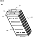
- FIG. 3 is a perspective view illustrating a battery cell stack 300 including a plurality of unit modules.
- the battery cell stack 300 includes four unit modules 200 and 201. Two battery cells (not shown) is mounted in each unit module 200. Consequently, a total of eight battery cells are included in the battery cell stack 300. Electrode terminals of the neighboring battery cells are connected in series with each other, and electrode terminals of the neighboring unit modules are also connected in series with each other. Electrode terminal connections 310 are bent in the sectional shape of a '[' to construct the battery cell stack. Outside electrode terminals 320 and 321 of the outermost unit modules 200 and 201 are bent inward in the sectional shape of a ' ⁇ ' such that the electrode terminals 320 and 321 protrude slightly more than the electrode terminal connections 310.
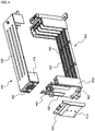
- FIG. 4 is an exploded perspective view illustrating upper and lower cases and a front cover of a middle- or large-sized battery module according to a preferred embodiment of the present invention.
- the upper case 400 is constructed in a structure to entirely surround one side end of the battery cell stack as shown in FIG. 3 and to partially surround the upper and lower ends of the battery cell stack.
- the upper case 400 is provided at the front part 410 thereof with a pair of external input and output terminals 420.
- the lower case 500 is constructed in a structure to entirely surround the other side end of the battery cell stack and to partially surround the upper and lower ends of the battery cell stack.
- the lower case 500 is coupled with the upper case 400.
- the lower case 500 is provided at the front part 510 thereof with a pair of bus bars 520 for connecting electrode terminals of the battery cell stack to the external input and output terminals 420.
- the upper and lower cases 400 and 500 are constructed in a structure in which, when the upper and lower cases 400 and 500 are coupled with each other, the upper and lower cases 400 and 500 surround only the edge of the battery cell stack (not shown), such that the outer surface of the battery cell stack is exposed to the outside, so as to accomplish easy heat dissipation of the battery cell stack.
- each bus bar 520 is formed in the shape of a depression such that the external input and output terminals 420 provided at the front part 410 of the upper case 400 are inserted into the depressions of the bus bars 520 when the upper and lower cases 400 and 500 are coupled with each other.
- the mounting grooves 530 are constructed in a structure in which the steps of the unit modules as shown in FIG. 2 are fitted in the corresponding mounting grooves 530.
- the upper case 400 and the lower case 500 are provided with pluralities of through-holes 430 and 532, through which a coolant (normally, air) flows, respectively, whereby effective cooling is accomplished while the battery cell stack is mounted in the upper case 400 and the lower case 500.
- a coolant normally, air
- the front cover 600 is made of an insulative material.
- each conductive member 440 is provided at one side thereof with a coupling insertion hole through which the corresponding external input and output terminal 420 is inserted. Also, each conductive member 440 includes a pair of bent parts for elastically surrounding the power cable.
- the front cover 600 is provided with fixing holes 610 for fixing the power cable. Insulative coupling members (not shown) are inserted through the corresponding fixing holes 610 such that the insulative coupling members are coupled with some of the power cable.
- the lower case 500 is provided at the front part 510 thereof with a pair of slits 522 which are formed at the right and left sides of the front part 510 of the lower case 500 such that the outermost electrode terminals (not shown) of the battery cell stack are inserted through the corresponding slits 522.
- the outermost electrode terminals of the battery cell stack are exposed through the slits 522 and then bent such that the outermost electrode terminals of the battery cell stack are brought into tight contact with the front part 510 of the lower case 500. Consequently, the outermost electrode terminals of the battery cell stack are more easily connected to the bus bars 520 located at the front part 510 of the lower case 500.
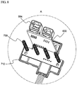
- FIGS. 5 and 6 are partial plan views respectively illustrating the front and rear parts of the middle- or large-sized battery module according to the present invention when unit modules are mounted to the lower case of the middle- or large-sized battery module.
- the lower case 500 is provided at the insides of the front part 510 and the rear part 540 thereof with pluralities of fixing grooves 550 in which the electrode terminal connections 310 of the unit modules 200 and electrode terminal connections 310 of the battery cells mounted in the respective unit modules 200 are inserted.
- the fixing grooves 550 are formed in a shape corresponding to the electrode terminal connections 310 and 270. Consequently, the fixing grooves 550 prevent the battery cell stack 300 from moving forward and rearward and maintain stable insulation between the neighboring electrode terminal connections.
- a cell cover movement preventing protrusion 552, a cell cover fixing guide 554, and an electrode terminal isolation wall 556 are formed in each fixing groove 550 for accomplishing more stable fixing and insulation of the unit modules 200.
- the lower case 500 is provided at the lower end of the front part thereof with a coupling part 560 which protrudes from the lower case 500 and has a through-hole 562 in the center thereof such that the lower case 500 is fixed to an external device (not shown).
- a protruding coupling part 570 formed at the lower end of the rear part of the lower case 500 includes a pair of opposite coupling parts 572 and 574.
- the coupling part 572 is formed such that the coupling part 572 is higher by a height equivalent to the thickness of the coupling part 574 than the coupling part 574. Consequently, when a middle- or large-sized battery system is manufactured using a plurality of battery modules, the coupling between the battery modules is easily accomplished, and the battery system is manufactured in a compact structure.
- the detailed structure of the protruding coupling part 570 is shown in FIG. 12 .
- BMS 600 battery management system 600.
- the BMS 600 is received in a BMS receiving part 580 integrally formed at the lower case 500.
- a thermistor connector 582 and a communication connector 584 are mounted at the BMS receiving part 580.
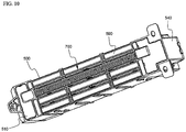
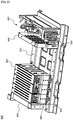
- FIGS. 7 to 10 are perspective views illustrating a voltage sensing member used in the middle- or large-sized battery module according to the present invention and how to mount the voltage sensing member to the battery module.
- the voltage sensing member 700 includes a pair of supporting parts 710 and 712 mounted to the bottom of the battery module 800 at regions corresponding to the electrode terminal connections 310 of the battery cells or the unit modules, a wire-shaped conduction part 720 for electrically interconnecting the supporting parts 710 and 712, pluralities of conductive compression springs 730 each having one end fixed to the corresponding support part 710 or 712 and the other end elastically connected to the corresponding electrode terminal connection 310, a BMS 600 mounted on the rear supporting part 712, and a connector 584.
- the voltage sensing member 700 with the above-described construction is mounted to the front part 510, the rear part 540, and the bottom 590 of the lower case 500 in an insertion fashion. Consequently, the battery module 800 is easily assembled and constructed in a stable structure.
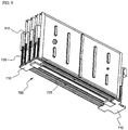
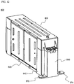
- FIGS. 11 and 12 are perspective views illustrating partially assembled states of the middle- or large-sized battery module according to the present invention.
- the battery module 800 is easily assembled by the coupling between the upper and lower case 400 and 500.
- the BMS (not shown) is received in the BMS receiving part 580 integrally formed at the rear part 540 of the lower case 500. Consequently, the battery module 800 is constructed in a simple and compact structure.
- two or more battery modules may be connected with each other by the coupling between the pair of coupling parts 572 and 574 formed at the lower end of the rear part 540 of the lower case 500 such that the pair of coupling parts 572 and 574 have different heights.
- FIG. 13 is a perspective view illustrating the assembly of a middle- or large-sized battery system according to a preferred embodiment of the present invention.
- the middle- or large-sized battery system 900 is constructed in a structure in which a plurality of battery modules 800 and 801, one of which is shown in FIG. 12 , are mounted on a frame 910, and the battery modules 800 and 801 are connected to an electric/electronic subassembly 930 located at one side of the frame 910 via a power cable (partially shown) 920.
- the electric/electronic subassembly 930 includes a master BMS connected to BMSs (not shown), i.e., slave BMSs, of the respective battery modules 800 and 801 for controlling the slave BMSs and various kinds of electric/electronic devices for controlling the overcharge, overdischarge, and overcurrent of the battery system 900 and input and output of power.
- BMSs i.e., slave BMSs
- various kinds of electric/electronic devices for controlling the overcharge, overdischarge, and overcurrent of the battery system 900 and input and output of power.
- the battery modules 800 and 801 are stably fixed to the frame 910 by the coupling part 560 and opposite supporting members 940 and 942, and therefore, the battery system is structurally stable when external impart is applied to the battery system.
- the present invention has the effect of easily mounting a sensing unit that is capable of minimizing the weight and size of battery cells while effectively reinforcing the low mechanical strength of the battery cells and sensing the operation state of the battery cells to a middle- or large-sized battery module.
- the present invention has the effect of manufacturing the battery module by a simple assembly process without using a plurality of members for mechanical coupling and electrical connection, thereby decreasing the manufacturing costs of the battery module, and effectively preventing the battery module from being short-circuited or damaged during the manufacture or the operation of the battery module.
- the present invention has the effect of manufacturing a middle- or large-sized battery system having desired output and capacity using the battery module as a unit body.
Claims (16)
- Module de batterie de taille moyenne ou grande (800) comprenant :un empilement de cellules de batterie (300), dans lequel l'empilement de cellules de batterie comprend une pluralité de modules unitaires incluant chacun des cellules de batterie en forme de plaque ayant des bornes d'électrode formées au niveau des extrémités supérieure et inférieure de ceux-ci, chaque cellule de batterie comprenant un ensemble à électrodes monté dans un boîtier de batterie en forme de poche, la pluralité de cellules de batterie ou de modules unitaires (200, 201) étant connectés électriquement les uns aux autres,dans lequel chaque module unitaire comprend deux ou plus des cellules de batterie construites dans une structure empilée dans laquelle les bornes d'électrode des cellules de batterie sont connectées en série les unes aux autres et des connexions de bornes d'électrode (310) sont incurvées de sorte que les cellules de batterie sont empilées, et une paire de couvercles de cellule à haute résistance (210, 220) pour entourer les surfaces externes des cellules de batterie à l'exclusion des bornes d'électrode des cellules de batterie lorsque les couvercles de cellule sont couplés les uns aux autres, les couvercles de cellule à haute résistance empêchant le changement de dilatation et de contraction répétitif des cellules de batterie pendant leur charge et leur décharge ;un premier boîtier de module (400) construit dans une structure pour entourer entièrement une extrémité latérale de l'empilement de cellules de batterie et pour entourer partiellement les extrémités supérieure et inférieure de l'empilement de cellules de batterie, le premier boîtier de module étant fourni au niveau d'une partie avant (410) de celui-ci avec des bornes d'entrée et de sortie externes (420) ;un second boîtier de module (500) couplé avec le premier boîtier de module, le second boîtier de module étant construit dans une structure pour entourer entièrement l'autre extrémité latérale de l'empilement de cellules de batterie et pour entourer partiellement les extrémités supérieure et inférieure de l'empilement de cellules de batterie, le second boîtier de module étant fourni au niveau d'une partie avant (510) de celui-ci avec des barres omnibus (520) pour connecter les bornes d'électrode (320, 321) de l'empilement de cellules de batterie aux bornes d'entrée et de sortie externes ;dans lequel les cellules de batterie ou modules unitaires, qui ont des bords latéraux opposés définis en tant que direction latérale, sont dressés dans la direction latérale, et dans lequel les premier et second boîtiers de module ont respectivement une pluralité de rainures de montage (530) dans lesquelles des bords des cellules de batterie ou modules unitaires sont insérés ;un élément de détection (700) monté sur le premier boîtier de module ou le second boîtier de module ; etun système de gestion de batterie (BMS) monté sur le premier boîtier de module ou le second boîtier de module, tout en étant connecté à l'élément de détection, pour surveiller et commander le fonctionnement du module de batterie,dans lequel l'extrémité supérieure de chaque barre omnibus (520) se présente sous la forme d'un enfoncement de sorte que les bornes d'entrée et de sortie externes (420) sont insérées dans les enfoncements des barres omnibus lorsque les premier et second boîtiers de module (400, 500) sont couplés l'un à l'autre.
- Module de batterie (800) selon la revendication 1, dans lequel le module de batterie comprend en outre un couvercle avant (600) monté sur la partie avant (510) du second boîtier de module (500) pour protéger des connexions entre les bornes d'électrode des cellules de batterie et les barres omnibus (520) contre l'extérieur, le couvercle avant étant réalisé en matériau isolant.
- Module de batterie (800) selon la revendication 2, dans lequel les couvercles de cellule (210, 220) sont pourvus au niveau des surfaces extérieures adjacentes aux extrémités supérieure et inférieure de ceux-ci de paliers (240) d'une taille prédéterminée pour fixer facilement les modules unitaires (200, 201), et les couvercles de cellule sont pourvus au niveau des surfaces externes adjacentes aux côtés opposés de ceux-ci de paliers (230) d'une taille prédéterminée pour fixer facilement les modules unitaires, les rainures de montage des premier et second boîtiers de module (400, 500) étant construites dans une structure correspondant aux paliers (230, 240).
- Module de batterie (800) selon la revendication 1, dans lequel le second boîtier de module (500) est doté au niveau des intérieurs des parties avant et arrière (510, 540) de celui-ci de pluralités de rainures de fixation (550) dans lesquelles les connexions de bornes d'électrode (310) sont insérées.
- Module de batterie (800) selon la revendication 1, dans lequel le second boîtier de module (500) est doté au niveau de la partie avant (510) de celui-ci d'une paire de fentes (522) à travers lesquelles les bornes d'électrode les plus à l'extérieur de l'empilement de cellules de batterie (300) sont insérées.
- Module de batterie (800) selon la revendication 5, dans lequel les bornes d'électrode les plus à l'extérieur de l'empilement de cellules de batterie (300) sont insérées à travers les fentes (522) et ensuite incurvées de sorte que les bornes d'électrode les plus à l'extérieur sont connectées aux barres omnibus (520) situées au niveau de la partie avant (510) du second boîtier de module (500).
- Module de batterie (800) selon la revendication 2, comprenant en outre :
un élément conducteur (440) monté sur au moins l'une des bornes d'entrée et de sortie externes (420) pour fixer l'extrémité supérieure du couvercle avant (600) et aider à la connexion d'un câble d'alimentation nécessaire à la connexion électrique. - Module de batterie (800) selon la revendication 2, dans lequel le couvercle avant (600) est couplé au second module (500) à la manière d'un couplage d'ensemble.
- Module de batterie (800) selon la revendication 2, dans lequel le couvercle avant (600) est doté de trous (610) pour fixer un câble d'alimentation.
- Module de batterie (800) selon la revendication 2, dans lequel le second boîtier de module (500) est doté au niveau de l'extrémité inférieure de la partie avant et/ou arrière (510, 540) de celui-ci d'une partie de couplage (560) qui fait saillie à partir du second boîtier de module et a un trou débouchant (562) dans le centre de celui-ci de sorte que le second boîtier de module est fixé à un dispositif externe.
- Module de batterie (800) selon la revendication 10, dans lequel la partie de couplage (560) formée au niveau de l'extrémité inférieure de la partie avant ou arrière (510, 540) du second boîtier de module (500) inclut une paire de parties de couplage faisant saillie (572, 574) construites de sorte que l'une des parties de couplage faisant saillie (572) est plus haute d'une hauteur équivalente à l'épaisseur de l'autre partie de couplage faisant saillie (574) que l'autre partie de couplage faisant saillie.
- Module de batterie (800) selon la revendication 2, dans lequel le second boîtier de module (500) est doté au niveau de la partie arrière (540) de celui-ci d'une partie de réception de BMS faisant saillie (580) dans laquelle le BMS est reçu.
- Module de batterie (800) selon la revendication 1, comprenant en outre :
des thermistances montées sur les cellules de batterie ou modules unitaires (200, 201) de l'empilement de cellules de batterie (300), les thermistances étant connectées au BMS. - Module de batterie (800) selon la revendication 12, dans lequel la partie de réception de BMS (580) est dotée d'un connecteur de thermistance (582) et d'un connecteur de communication (584).
- Système de batterie de taille moyenne ou grande (900) comprenant un module de batterie (800) selon la revendication 1 en tant que corps unitaire.
- Source d'alimentation pour véhicules électriques ou véhicules électriques hybrides comprenant le système de batterie (900) selon la revendication 15.
Applications Claiming Priority (3)
| Application Number | Priority Date | Filing Date | Title |
|---|---|---|---|
| KR1020060020772A KR100948002B1 (ko) | 2006-03-06 | 2006-03-06 | 중대형 전지모듈 |
| KR1020060045443A KR100896131B1 (ko) | 2006-05-22 | 2006-05-22 | 중대형 전지모듈 |
| PCT/KR2007/001017 WO2007102670A1 (fr) | 2006-03-06 | 2007-02-28 | Module de batterie de taille moyenne ou grande |
Publications (3)
| Publication Number | Publication Date |
|---|---|
| EP1994582A1 EP1994582A1 (fr) | 2008-11-26 |
| EP1994582A4 EP1994582A4 (fr) | 2010-04-14 |
| EP1994582B1 true EP1994582B1 (fr) | 2019-12-04 |
Family
ID=38475075
Family Applications (1)
| Application Number | Title | Priority Date | Filing Date |
|---|---|---|---|
| EP07715427.6A Active EP1994582B1 (fr) | 2006-03-06 | 2007-02-28 | Module de batterie de taille moyenne ou grande |
Country Status (5)
| Country | Link |
|---|---|
| US (3) | US7892669B2 (fr) |
| EP (1) | EP1994582B1 (fr) |
| JP (1) | JP5344932B2 (fr) |
| TW (1) | TWI368345B (fr) |
| WO (1) | WO2007102670A1 (fr) |
Families Citing this family (98)
| Publication number | Priority date | Publication date | Assignee | Title |
|---|---|---|---|---|
| KR100948002B1 (ko) * | 2006-03-06 | 2010-03-18 | 주식회사 엘지화학 | 중대형 전지모듈 |
| EP1992026B1 (fr) * | 2006-03-06 | 2019-08-07 | LG Chem, Ltd. | Module de batterie |
| US9484591B2 (en) * | 2006-03-06 | 2016-11-01 | Lg Chem, Ltd. | Voltage sensing member and battery module employed with the same |
| EP1994582B1 (fr) | 2006-03-06 | 2019-12-04 | LG Chem, Ltd. | Module de batterie de taille moyenne ou grande |
| KR100876267B1 (ko) * | 2007-10-04 | 2008-12-26 | 삼성에스디아이 주식회사 | 이차전지 |
| DE102007059805A1 (de) | 2007-12-11 | 2009-06-25 | Evonik Degussa Gmbh | Batteriepack |
| WO2010031858A2 (fr) * | 2008-09-18 | 2010-03-25 | Magna Steyr Fahrzeugtechnik Ag & Co Kg | Rail de liaison pour éléments d'accumulateur et utilisation dudit rail |
| CN102204006A (zh) * | 2008-09-30 | 2011-09-28 | 玛格纳E-汽车系统有限两合公司 | 储能单元 |
| KR100937897B1 (ko) | 2008-12-12 | 2010-01-21 | 주식회사 엘지화학 | 신규한 공냉식 구조의 중대형 전지팩 |
| US9028986B2 (en) * | 2009-01-07 | 2015-05-12 | A123 Systems Llc | Fuse for battery cells |
| US8257855B2 (en) * | 2009-01-12 | 2012-09-04 | A123 Systems, Inc. | Prismatic battery module with scalable architecture |
| US8951655B2 (en) * | 2009-02-27 | 2015-02-10 | Lg Chem, Ltd. | Middle or large-sized battery pack case providing improved distribution uniformity in coolant flux |
| JP5434161B2 (ja) * | 2009-03-13 | 2014-03-05 | 日産自動車株式会社 | 組電池 |
| JP4947075B2 (ja) * | 2009-03-23 | 2012-06-06 | トヨタ自動車株式会社 | 蓄電装置の温度調節構造 |
| KR101130046B1 (ko) * | 2009-04-01 | 2012-03-28 | 주식회사 엘지화학 | 안전성이 향상된 중대형 전지모듈 |
| KR101023921B1 (ko) * | 2009-04-01 | 2011-03-22 | 주식회사 엘지화학 | 전압 검출부재 및 이를 포함하는 전지모듈 |
| CN104253250B (zh) * | 2009-05-04 | 2016-09-07 | 株式会社Lg化学 | 电池模块和包括该电池模块的电池组 |
| US8580423B2 (en) * | 2009-10-22 | 2013-11-12 | Samsung Sdi Co., Ltd. | Bus bar holder and battery pack including the same |
| US20130122339A1 (en) * | 2009-11-27 | 2013-05-16 | V-Ens Co., Ltd. | Battery |
| KR101097257B1 (ko) | 2009-12-03 | 2011-12-21 | 삼성에스디아이 주식회사 | 회로 기판 모듈과, 이를 적용한 전지 모듈 |
| WO2011067695A1 (fr) | 2009-12-04 | 2011-06-09 | Brusa Elektronik Ag | Borne pour cellules d'accumulateur |
| CN102696130B (zh) * | 2009-12-04 | 2015-05-27 | 布鲁萨电子公司 | 具有温度调节的电池 |
| KR101097264B1 (ko) | 2010-01-18 | 2011-12-21 | 삼성에스디아이 주식회사 | 센싱보드가 내장된 배터리팩과 그것을 채용한 전력저장시스템 |
| KR101152635B1 (ko) * | 2010-04-08 | 2012-06-04 | 주식회사 엘지화학 | 전지모듈용 전압 검출 어셈블리 및 이를 포함하는 전지모듈 |
| KR101230954B1 (ko) * | 2010-04-08 | 2013-02-07 | 주식회사 엘지화학 | 신규한 구조의 센싱부재를 포함하는 전지모듈 |
| WO2011129545A2 (fr) | 2010-04-13 | 2011-10-20 | 주식회사 엘지화학 | Boîtier de bloc-batterie ayant une nouvelle structure |
| KR101297176B1 (ko) * | 2010-06-03 | 2013-08-21 | 주식회사 엘지화학 | 신규한 구조의 전지모듈 |
| KR101256078B1 (ko) | 2010-06-10 | 2013-04-18 | 로베르트 보쉬 게엠베하 | 충전 장치 |
| KR101217564B1 (ko) * | 2010-08-16 | 2013-01-02 | 주식회사 엘지화학 | 전압 검출 어셈블리 및 이를 포함하는 전지모듈 |
| KR101680709B1 (ko) * | 2010-11-12 | 2016-12-12 | 에스케이이노베이션 주식회사 | 배터리 모듈 케이스 |
| KR101836408B1 (ko) | 2011-04-20 | 2018-03-12 | 에스케이이노베이션 주식회사 | 배터리 셀 센싱 기판 |
| WO2012148100A2 (fr) * | 2011-04-26 | 2012-11-01 | 주식회사 엘지화학 | Nouvelle structure de barre omnibus, et module de batterie la comprenant |
| KR101252952B1 (ko) | 2011-05-02 | 2013-04-15 | 로베르트 보쉬 게엠베하 | 배터리 셀의 유동을 방지하는 배터리 모듈 |
| US9472797B2 (en) * | 2011-05-25 | 2016-10-18 | Samsung Sdi Co., Ltd. | Battery pack |
| GB2491816A (en) * | 2011-06-07 | 2012-12-19 | Leclancha S A | Modular battery with exchangeable cell elements |
| KR101469518B1 (ko) * | 2011-08-01 | 2014-12-05 | 주식회사 엘지화학 | 안전성이 향상된 전지모듈 |
| KR101480385B1 (ko) * | 2011-12-14 | 2015-01-09 | 주식회사 엘지화학 | 버스 바 어셈블리가 전면에 장착된 전지모듈 어셈블리 및 이를 포함하는 중대형 전지팩 |
| JP6186716B2 (ja) * | 2012-01-16 | 2017-08-30 | 株式会社Gsユアサ | 電源装置 |
| KR101447057B1 (ko) | 2012-01-26 | 2014-10-07 | 주식회사 엘지화학 | 전지셀의 장착 및 방열을 위한 방열 지지부재를 포함하는 전지모듈 |
| KR101285712B1 (ko) | 2012-02-27 | 2013-07-12 | 세방전지(주) | 전지팩 케이스 |
| ITBO20120183A1 (it) * | 2012-04-06 | 2013-10-07 | Ferrari Spa | Sistema di accumulo di energia elettrica per un veicolo con propulsione elettrica e presentante batteria chimiche cilindriche collegate tra loro in parallelo e serie mediante elementi di collegamento rigidi conformati ad "u" |
| KR20130121517A (ko) * | 2012-04-27 | 2013-11-06 | 삼성에스디아이 주식회사 | 이차 전지 |
| KR101456960B1 (ko) * | 2012-05-07 | 2014-11-03 | 주식회사 엘지화학 | 고정부재를 구비한 전지모듈 |
| KR101987778B1 (ko) * | 2012-05-11 | 2019-06-11 | 에스케이이노베이션 주식회사 | 냉각 유로 관통형 이차전지모듈 |
| KR102122930B1 (ko) * | 2012-11-27 | 2020-06-15 | 에스케이이노베이션 주식회사 | 전지 모듈 및 이를 포함하는 전지 팩 |
| JP5954585B2 (ja) * | 2013-04-05 | 2016-07-20 | 株式会社オートネットワーク技術研究所 | 機器用コネクタ |
| DE102013207592B3 (de) * | 2013-04-25 | 2014-08-07 | Magna Steyr Battery Systems Gmbh & Co Og | Batteriesystem |
| US9876203B2 (en) | 2013-05-15 | 2018-01-23 | Lg Chem, Ltd. | Battery module assembly with novel structure |
| JP6058163B2 (ja) * | 2013-05-15 | 2017-01-11 | エルジー・ケム・リミテッド | 新規な構造の電池モジュールアセンブリー |
| DE102013011741A1 (de) * | 2013-07-12 | 2015-01-15 | Daimler Ag | Energiespeichervorrichtung, Verfahren zum Herstellen dieser Energiespeichervorrichtung |
| KR101805757B1 (ko) | 2013-08-23 | 2017-12-07 | 주식회사 엘지화학 | 전면에 bms의 통신단자가 돌출되어 있는 전지모듈 어셈블리 |
| KR101729553B1 (ko) * | 2013-08-23 | 2017-04-24 | 주식회사 엘지화학 | 전력 저장 장치용 전지팩 |
| KR102258973B1 (ko) | 2013-10-31 | 2021-06-02 | 타이코에이엠피 주식회사 | 센싱 블록 및 이를 포함하는 배터리 패키지 |
| US10218027B2 (en) | 2013-11-11 | 2019-02-26 | A123 Systems, LLC | Vehicle starter battery |
| KR101841663B1 (ko) * | 2014-03-06 | 2018-05-04 | 주식회사 엘지화학 | 리셉터클 구조의 전압 센싱부재를 포함하는 전지모듈 |
| JP6552059B2 (ja) | 2014-04-03 | 2019-07-31 | エルジー・ケム・リミテッド | バッテリーモジュールアレイ |
| USD783530S1 (en) * | 2014-06-10 | 2017-04-11 | Hitachi Chemical Company, Ltd. | Case for electric power storage cell pack |
| KR101773105B1 (ko) * | 2014-07-31 | 2017-08-30 | 주식회사 엘지화학 | 배터리 모듈 |
| US9461286B2 (en) * | 2014-08-25 | 2016-10-04 | Ford Global Technologies, Llc | Twist-lock battery pack attachment device |
| DE102014114020A1 (de) * | 2014-09-26 | 2016-03-31 | Obrist Technologies Gmbh | Batteriesystem |
| US9520587B2 (en) * | 2014-09-30 | 2016-12-13 | Johnson Controls Technology Company | Bus bar assembly carrier |
| US9911951B2 (en) | 2014-09-30 | 2018-03-06 | Johnson Controls Technology Company | Battery module compressed cell assembly |
| KR101822839B1 (ko) * | 2015-03-16 | 2018-03-08 | 주식회사 엘지화학 | 팩 케이스와 이를 포함하는 전지 팩 |
| KR101939832B1 (ko) * | 2015-09-23 | 2019-01-17 | 주식회사 엘지화학 | 배터리 모듈, 이를 포함하는 배터리 팩 및 배터리 모듈용 케이싱 제조 방법 |
| KR102019472B1 (ko) * | 2015-10-05 | 2019-09-06 | 주식회사 엘지화학 | 배터리 모듈 및 이를 포함하는 배터리 팩 |
| JP6625741B2 (ja) * | 2015-10-16 | 2019-12-25 | ローベルト ボツシユ ゲゼルシヤフト ミツト ベシユレンクテル ハフツングRobert Bosch Gmbh | 組み込まれたばねまたは可撓性パッドを備えるバッテリ端子 |
| KR101991925B1 (ko) * | 2015-12-04 | 2019-06-21 | 주식회사 엘지화학 | 그립핑부가 구비되어 있는 카트리지를 포함하고 있는 전지모듈 |
| WO2018033880A2 (fr) | 2016-08-17 | 2018-02-22 | Shape Corp. | Structure de support et de protection de batterie pour un véhicule |
| TWM533365U (en) * | 2016-08-25 | 2016-12-01 | Formosa Electronic Ind Inc | Plug-in connection structure of stacked energy-storage battery module |
| CN106450086A (zh) * | 2016-10-13 | 2017-02-22 | 江苏金坛绿能新能源科技有限公司 | 一种软包装电池转运装置 |
| US11214137B2 (en) | 2017-01-04 | 2022-01-04 | Shape Corp. | Vehicle battery tray structure with nodal modularity |
| KR102140311B1 (ko) | 2017-04-07 | 2020-07-31 | 주식회사 엘지화학 | 배터리 모듈과 이를 포함하는 배터리 팩 및 자동차 |
| WO2018213475A1 (fr) | 2017-05-16 | 2018-11-22 | Shape Corp. | Support de batterie polarisé pour véhicule |
| US11211656B2 (en) | 2017-05-16 | 2021-12-28 | Shape Corp. | Vehicle battery tray with integrated battery retention and support feature |
| WO2018213306A1 (fr) | 2017-05-16 | 2018-11-22 | Shape Corp. | Plateau à batterie de véhicule ayant un composant à base de bac |
| KR102164632B1 (ko) * | 2017-07-31 | 2020-10-12 | 주식회사 엘지화학 | 배터리 모듈, 이를 포함하는 배터리 팩 및 전력 저장 장치 |
| WO2019055658A2 (fr) | 2017-09-13 | 2019-03-21 | Shape Corp. | Plateau de batterie de véhicule à paroi périphérique tubulaire |
| DE112018005556T5 (de) | 2017-10-04 | 2020-06-25 | Shape Corp. | Batterieträger-bodenbaugruppe für elektrofahrzeuge |
| DE102017127064B4 (de) | 2017-11-17 | 2021-11-04 | Dr. Ing. H.C. F. Porsche Aktiengesellschaft | Batterierahmen |
| KR102280997B1 (ko) * | 2017-12-20 | 2021-07-22 | 주식회사 엘지에너지솔루션 | 전지 모듈 및 이를 포함하는 전지팩 |
| EP3759761A4 (fr) | 2018-03-01 | 2021-09-08 | Shape Corp. | Système de refroidissement intégré à un bac de batterie de véhicule |
| KR102150679B1 (ko) * | 2018-03-13 | 2020-09-01 | 주식회사 엘지화학 | 배터리 모듈, 이러한 배터리 모듈을 포함하는 배터리 팩 및 이러한 배터리 팩을 포함하는 자동차 |
| US11688910B2 (en) | 2018-03-15 | 2023-06-27 | Shape Corp. | Vehicle battery tray having tub-based component |
| DE102018213290A1 (de) * | 2018-08-08 | 2020-02-13 | Robert Bosch Gmbh | Batterieaufnahmesystem und Batteriesystem |
| KR20200052676A (ko) * | 2018-11-07 | 2020-05-15 | 에스케이이노베이션 주식회사 | 배터리 모듈 |
| KR102443098B1 (ko) * | 2018-11-12 | 2022-09-13 | 주식회사 엘지에너지솔루션 | 모듈 하우징을 포함한 배터리 모듈 |
| KR102392788B1 (ko) * | 2019-01-08 | 2022-04-28 | 주식회사 엘지에너지솔루션 | 폴더블 사이드 플레이트를 구비하는 배터리 모듈 및 그 제조 방법 |
| KR102465864B1 (ko) * | 2019-06-12 | 2022-11-09 | 주식회사 엘지에너지솔루션 | 전지 모듈 및 이를 포함하는 전지팩 |
| KR102503536B1 (ko) * | 2019-06-18 | 2023-02-23 | 주식회사 엘지에너지솔루션 | 전지 모듈 및 이를 포함하는 전지팩 |
| EP3772124A4 (fr) * | 2019-06-18 | 2021-06-23 | Lg Chem, Ltd. | Module de batterie et bloc-batterie le comprenant |
| CN111093341B (zh) * | 2019-12-27 | 2021-09-28 | 常州工学院 | 一种用于电源模块的固定安装装置 |
| KR20210108209A (ko) * | 2020-02-25 | 2021-09-02 | 에스케이이노베이션 주식회사 | 배터리 모듈 |
| JP2023516735A (ja) * | 2020-03-05 | 2023-04-20 | 3 エムイー テクノロジー プロプライエタリー リミテッド | バッテリのための装置、システム、及び方法 |
| JP7419538B2 (ja) * | 2020-07-10 | 2024-01-22 | 寧徳時代新能源科技股▲分▼有限公司 | 電池、その関連装置、製造方法及び製造機器 |
| EP4307451A3 (fr) | 2020-07-10 | 2024-03-13 | Contemporary Amperex Technology Co., Limited | Boîtier de batterie, batterie, dispositif de consommation d'énergie et procédé et dispositif de préparation de batterie |
| KR20220095224A (ko) | 2020-07-10 | 2022-07-06 | 컨템포러리 엠퍼렉스 테크놀로지 씨오., 리미티드 | 배터리 및 관련 장치, 제조 방법 및 제조 장치 |
| EP3958378B1 (fr) | 2020-07-10 | 2023-12-13 | Contemporary Amperex Technology Co., Limited | Batterie, dispositif électrique, et procédé et dispositif de préparation de batterie |
| KR20220045353A (ko) * | 2020-10-05 | 2022-04-12 | 현대자동차주식회사 | 배터리 모듈 |
Citations (4)
| Publication number | Priority date | Publication date | Assignee | Title |
|---|---|---|---|---|
| US20040033415A1 (en) * | 2002-08-19 | 2004-02-19 | Allis Electric Co., Ltd. | Mobile rack type battery box for UPS system |
| US20040036444A1 (en) * | 2002-07-04 | 2004-02-26 | Nissan Motor Co., Ltd. | Module battery |
| US20040050414A1 (en) * | 2002-07-30 | 2004-03-18 | Nissan Motor Co., Ltd. | Module battery |
| JP2005222699A (ja) * | 2004-02-03 | 2005-08-18 | Shin Kobe Electric Mach Co Ltd | 組電池 |
Family Cites Families (70)
| Publication number | Priority date | Publication date | Assignee | Title |
|---|---|---|---|---|
| US4278744A (en) * | 1975-12-19 | 1981-07-14 | Duracell International Inc. | Expandable casing for electro-chemical cells |
| JPS61171065A (ja) | 1985-01-24 | 1986-08-01 | Japan Storage Battery Co Ltd | 熱電池 |
| JPH0214666U (fr) * | 1988-07-08 | 1990-01-30 | ||
| US4957829A (en) * | 1989-06-26 | 1990-09-18 | At&T Bell Laboratories | Modular battery plant system assembly comprising multiple unit cell modules |
| US5366827A (en) | 1992-06-10 | 1994-11-22 | Digital Equipment Corporation | Modular housing for batteries and battery charger |
| US5558950A (en) * | 1993-03-05 | 1996-09-24 | Ovonic Battery Company, Inc. | Optimized cell pack for large sealed nickel-metal hydride batteries |
| US5437939A (en) * | 1994-01-06 | 1995-08-01 | Gnb Industrial Battery Company | Sealed lead-acid battery tray assemblies and motive power vehicles using such battery tray assemblies |
| JP3260951B2 (ja) * | 1994-02-23 | 2002-02-25 | 松下電器産業株式会社 | 密閉形アルカリ蓄電池の単電池及び単位電池 |
| WO1997036337A1 (fr) | 1996-03-22 | 1997-10-02 | Hitachi, Ltd. | Pile secondaire au lithium, chargeur et dispositif pour terminal informatique |
| US5639571A (en) * | 1996-06-24 | 1997-06-17 | General Motors Corporation | Battery pack |
| JPH10129276A (ja) | 1996-10-25 | 1998-05-19 | Suzuki Motor Corp | 電気自動車用バッテリ固定構造 |
| US5981101A (en) | 1997-06-02 | 1999-11-09 | Gnb Technologies, Inc. | Modular cell tray assembly for sealed lead-acid cells |
| US6191591B1 (en) | 1998-05-29 | 2001-02-20 | Moltech Power Systems, Inc. | Battery cell grading holder |
| JP2000100481A (ja) * | 1998-09-18 | 2000-04-07 | Fuji Heavy Ind Ltd | 電動車両用バッテリボックス |
| JP4837155B2 (ja) * | 1998-11-27 | 2011-12-14 | パナソニック株式会社 | 蓄電池 |
| GB9900396D0 (en) | 1999-01-08 | 1999-02-24 | Danionics As | Arrangements of electrochemical cells |
| DE10002142B4 (de) | 1999-01-28 | 2004-04-29 | Sanyo Electric Co., Ltd., Moriguchi | Stromversorgung enthaltend wiederaufladbare Batterien |
| JP4631118B2 (ja) * | 1999-02-15 | 2011-02-16 | ソニー株式会社 | 移動体搭載用バッテリ装置 |
| EP1071147A1 (fr) | 1999-07-19 | 2001-01-24 | Toshiba Battery Co., Ltd. | Bloc-batterie |
| JP4572019B2 (ja) * | 1999-10-08 | 2010-10-27 | パナソニック株式会社 | 組電池 |
| JP4559566B2 (ja) * | 1999-10-08 | 2010-10-06 | パナソニック株式会社 | 角形密閉式電池 |
| JP2001332235A (ja) * | 2000-05-25 | 2001-11-30 | Yazaki Corp | バッテリカバー |
| CA2350702A1 (fr) * | 2000-06-16 | 2001-12-16 | Nisshinbo Industries, Inc. | Batterie a polymere et methode de fabrication connexe |
| US6482544B1 (en) | 2000-06-30 | 2002-11-19 | Mitsubishi Denki Kabushiki Kaisha | Battery package |
| JP2002313295A (ja) | 2001-04-11 | 2002-10-25 | Gs-Melcotec Co Ltd | 二次電池パック |
| JP2002313398A (ja) | 2001-04-16 | 2002-10-25 | Mitsubishi Heavy Ind Ltd | セル電圧測定用ピックアップユニット |
| US20020182480A1 (en) * | 2001-06-04 | 2002-12-05 | Hanauer Brad T. | Electrical energy storage pack |
| US20030039881A1 (en) | 2001-08-22 | 2003-02-27 | Mount Robert L. | Battery accessible modules for rack mount systems |
| JP2003068259A (ja) | 2001-08-30 | 2003-03-07 | Nec Eng Ltd | 電 池 |
| JP3955449B2 (ja) | 2001-09-10 | 2007-08-08 | 本田技研工業株式会社 | 燃料電池のセル電圧検出装置 |
| JP2003123721A (ja) | 2001-10-18 | 2003-04-25 | Toyota Motor Corp | 組電池 |
| JP3891860B2 (ja) * | 2002-02-26 | 2007-03-14 | トヨタ自動車株式会社 | 集合電池および電池システム |
| DE60307750T2 (de) * | 2002-05-08 | 2006-12-14 | Nissan Motor Co., Ltd., Yokohama | Sekundärzellenmodul und Verfahren zu dessen Herstellung |
| JP3594023B2 (ja) * | 2002-07-30 | 2004-11-24 | 日産自動車株式会社 | 電池モジュール |
| JP2004079316A (ja) * | 2002-08-15 | 2004-03-11 | Nisshinbo Ind Inc | 急速充電電池用充電システム |
| JP3614158B2 (ja) | 2002-08-21 | 2005-01-26 | ソニー株式会社 | バッテリーパック |
| US7063212B2 (en) * | 2002-09-19 | 2006-06-20 | Bill Thomas Associates, Inc. | Multiple seal storage and transport container |
| US20040137321A1 (en) | 2002-11-27 | 2004-07-15 | Jean-Francois Savaria | Casing for an energy storage device |
| KR100958647B1 (ko) * | 2002-12-18 | 2010-05-20 | 삼성에스디아이 주식회사 | 파우치형 이차전지 유니트 |
| US20060183017A1 (en) * | 2003-03-31 | 2006-08-17 | Takeshi Kanai | Radiating member for laminated battery and method of manufacturing the same |
| JP4238645B2 (ja) | 2003-06-12 | 2009-03-18 | 日産自動車株式会社 | バイポーラ電池 |
| US7118827B2 (en) * | 2003-08-06 | 2006-10-10 | Delphi Technologies, Inc. | Battery assembly and method of making same |
| KR100560158B1 (ko) | 2003-09-29 | 2006-03-16 | 주식회사 코캄 | 고 안전성 리튬 이차 전지 및 그 제조방법 |
| JP4547886B2 (ja) | 2003-09-30 | 2010-09-22 | トヨタ自動車株式会社 | 組電池 |
| JP3972884B2 (ja) * | 2003-10-10 | 2007-09-05 | 日産自動車株式会社 | 組電池 |
| JP4706170B2 (ja) | 2003-10-14 | 2011-06-22 | 株式会社Gsユアサ | 組電池 |
| CN102340028B (zh) * | 2003-10-14 | 2014-07-02 | 株式会社Lg化学 | 盒式锂离子聚合物电池组 |
| JP4701658B2 (ja) * | 2003-10-14 | 2011-06-15 | 日産自動車株式会社 | 電池モジュール、および、組電池 |
| JP4078553B2 (ja) * | 2003-10-21 | 2008-04-23 | 新神戸電機株式会社 | 車両用リチウム電池モジュール |
| JP2005197179A (ja) | 2004-01-09 | 2005-07-21 | Toyota Motor Corp | 単電池および組電池 |
| JP4662530B2 (ja) * | 2004-01-20 | 2011-03-30 | パナソニック株式会社 | 電池パック |
| WO2005074054A1 (fr) | 2004-01-30 | 2005-08-11 | Lg Chem, Ltd. | Batterie ayant une structure d'enveloppe specifique |
| JP2005222701A (ja) * | 2004-02-03 | 2005-08-18 | Shin Kobe Electric Mach Co Ltd | 組電池 |
| JP2005276516A (ja) * | 2004-03-23 | 2005-10-06 | Nec Tokin Corp | 二次電池およびその製造方法 |
| JP2005286430A (ja) * | 2004-03-26 | 2005-10-13 | Sharp Corp | 携帯機器 |
| JP4632683B2 (ja) | 2004-03-31 | 2011-02-16 | 日本電気株式会社 | フィルム外装電池用の電池加圧部材 |
| JP4617098B2 (ja) | 2004-04-12 | 2011-01-19 | 内山工業株式会社 | バッテリーセル用ケース |
| JP4642838B2 (ja) | 2004-04-16 | 2011-03-02 | エルジー・ケム・リミテッド | 電池用安全素子及びこれを備えた電池 |
| JP4457812B2 (ja) | 2004-08-30 | 2010-04-28 | 新神戸電機株式会社 | 組電池及びモジュール電池 |
| JP4747539B2 (ja) | 2004-09-13 | 2011-08-17 | マックス株式会社 | 電池パック |
| US7989104B2 (en) * | 2004-10-28 | 2011-08-02 | Samsung Sdi Co., Ltd. | Battery module |
| KR100860002B1 (ko) | 2004-11-15 | 2008-09-25 | 주식회사 엘지화학 | 교번 배향 구조의 이차전지 팩 |
| WO2006059434A1 (fr) | 2004-11-30 | 2006-06-08 | Nec Corporation | Ensemble d’appareils electriques |
| KR100857021B1 (ko) * | 2004-12-10 | 2008-09-05 | 주식회사 엘지화학 | 결착식 전지팩 |
| TW200629628A (en) * | 2005-02-04 | 2006-08-16 | Li-Han Yao | Battery pack |
| US20070134551A1 (en) | 2005-12-14 | 2007-06-14 | Avestor Limited Partnership | Electrochemical battery and method for making same |
| WO2007079449A2 (fr) * | 2006-01-03 | 2007-07-12 | Johnson Controls Technology Company | Systeme de batterie |
| KR100920210B1 (ko) * | 2006-02-09 | 2009-10-05 | 주식회사 엘지화학 | 전지모듈 제조용 프레임 부재 |
| EP1994582B1 (fr) * | 2006-03-06 | 2019-12-04 | LG Chem, Ltd. | Module de batterie de taille moyenne ou grande |
| KR101023921B1 (ko) | 2009-04-01 | 2011-03-22 | 주식회사 엘지화학 | 전압 검출부재 및 이를 포함하는 전지모듈 |
-
2007
- 2007-02-28 EP EP07715427.6A patent/EP1994582B1/fr active Active
- 2007-02-28 JP JP2008558182A patent/JP5344932B2/ja active Active
- 2007-02-28 US US12/224,688 patent/US7892669B2/en active Active
- 2007-02-28 WO PCT/KR2007/001017 patent/WO2007102670A1/fr active Application Filing
- 2007-03-05 TW TW096107478A patent/TWI368345B/zh active
-
2011
- 2011-01-07 US US12/986,426 patent/US8968901B2/en active Active
-
2015
- 2015-01-23 US US14/604,208 patent/US9620826B2/en active Active
Patent Citations (4)
| Publication number | Priority date | Publication date | Assignee | Title |
|---|---|---|---|---|
| US20040036444A1 (en) * | 2002-07-04 | 2004-02-26 | Nissan Motor Co., Ltd. | Module battery |
| US20040050414A1 (en) * | 2002-07-30 | 2004-03-18 | Nissan Motor Co., Ltd. | Module battery |
| US20040033415A1 (en) * | 2002-08-19 | 2004-02-19 | Allis Electric Co., Ltd. | Mobile rack type battery box for UPS system |
| JP2005222699A (ja) * | 2004-02-03 | 2005-08-18 | Shin Kobe Electric Mach Co Ltd | 組電池 |
Also Published As
| Publication number | Publication date |
|---|---|
| TWI368345B (en) | 2012-07-11 |
| US9620826B2 (en) | 2017-04-11 |
| EP1994582A1 (fr) | 2008-11-26 |
| JP2009529217A (ja) | 2009-08-13 |
| US20110135994A1 (en) | 2011-06-09 |
| US20150162648A1 (en) | 2015-06-11 |
| US20090305116A1 (en) | 2009-12-10 |
| US7892669B2 (en) | 2011-02-22 |
| EP1994582A4 (fr) | 2010-04-14 |
| TW200814404A (en) | 2008-03-16 |
| US8968901B2 (en) | 2015-03-03 |
| WO2007102670A1 (fr) | 2007-09-13 |
| JP5344932B2 (ja) | 2013-11-20 |
Similar Documents
| Publication | Publication Date | Title |
|---|---|---|
| EP1994582B1 (fr) | Module de batterie de taille moyenne ou grande | |
| EP1994581B1 (fr) | Module de batterie de taille moyenne ou grande | |
| EP1992026B1 (fr) | Module de batterie | |
| US9640790B2 (en) | Middle or large-sized battery module | |
| EP2538466B1 (fr) | Module de batterie comprenant des éléments de détection à structure innovatrice | |
| EP2535962B1 (fr) | Module accumulateur ayant une fiabilité de soudage améliorée, ainsi que batterie d'accumulateurs de dimension moyenne ou grande et comprenant celui-ci | |
| KR100896131B1 (ko) | 중대형 전지모듈 | |
| EP1982366B1 (fr) | Module de batterie | |
| EP2672284B1 (fr) | Ensemble de détection de tension et module de batterie le comprenant | |
| EP2760063B1 (fr) | Ensemble bloc-batterie de grande taille et de taille moyenne | |
| KR101326182B1 (ko) | 외장부재와 카트리지를 포함하는 단위모듈에 기반한 전지모듈 | |
| KR20070112490A (ko) | 전지모듈 | |
| KR101305229B1 (ko) | 외장부재와 방열부재를 포함하는 단위모듈 및 이를 포함하는 전지모듈 | |
| KR101136807B1 (ko) | 중대형 전지모듈용 카트리지 |
Legal Events
| Date | Code | Title | Description |
|---|---|---|---|
| PUAI | Public reference made under article 153(3) epc to a published international application that has entered the european phase |
Free format text: ORIGINAL CODE: 0009012 |
|
| 17P | Request for examination filed |
Effective date: 20080903 |
|
| AK | Designated contracting states |
Kind code of ref document: A1 Designated state(s): DE FR IT |
|
| RBV | Designated contracting states (corrected) |
Designated state(s): DE FR IT |
|
| RIN1 | Information on inventor provided before grant (corrected) |
Inventor name: YANG, HEEKOOK Inventor name: YOON, JONGMOON Inventor name: YANG, JAE HUN |
|
| RBV | Designated contracting states (corrected) |
Designated state(s): DE FR IT |
|
| A4 | Supplementary search report drawn up and despatched |
Effective date: 20100316 |
|
| 17Q | First examination report despatched |
Effective date: 20100818 |
|
| DAX | Request for extension of the european patent (deleted) | ||
| RAP1 | Party data changed (applicant data changed or rights of an application transferred) |
Owner name: LG CHEM, LTD. |
|
| RIC1 | Information provided on ipc code assigned before grant |
Ipc: H01M 2/20 20060101ALI20190506BHEP Ipc: H01M 2/10 20060101AFI20190506BHEP Ipc: H01M 2/02 20060101ALI20190506BHEP Ipc: H01M 10/48 20060101ALI20190506BHEP |
|
| GRAP | Despatch of communication of intention to grant a patent |
Free format text: ORIGINAL CODE: EPIDOSNIGR1 |
|
| INTG | Intention to grant announced |
Effective date: 20190624 |
|
| GRAS | Grant fee paid |
Free format text: ORIGINAL CODE: EPIDOSNIGR3 |
|
| GRAA | (expected) grant |
Free format text: ORIGINAL CODE: 0009210 |
|
| AK | Designated contracting states |
Kind code of ref document: B1 Designated state(s): DE FR IT |
|
| REG | Reference to a national code |
Ref country code: DE Ref legal event code: R096 Ref document number: 602007059563 Country of ref document: DE |
|
| REG | Reference to a national code |
Ref country code: DE Ref legal event code: R097 Ref document number: 602007059563 Country of ref document: DE |
|
| PLBE | No opposition filed within time limit |
Free format text: ORIGINAL CODE: 0009261 |
|
| STAA | Information on the status of an ep patent application or granted ep patent |
Free format text: STATUS: NO OPPOSITION FILED WITHIN TIME LIMIT |
|
| 26N | No opposition filed |
Effective date: 20200907 |
|
| REG | Reference to a national code |
Ref country code: DE Ref legal event code: R079 Ref document number: 602007059563 Country of ref document: DE Free format text: PREVIOUS MAIN CLASS: H01M0002100000 Ipc: H01M0050200000 |
|
| PG25 | Lapsed in a contracting state [announced via postgrant information from national office to epo] |
Ref country code: IT Free format text: LAPSE BECAUSE OF FAILURE TO SUBMIT A TRANSLATION OF THE DESCRIPTION OR TO PAY THE FEE WITHIN THE PRESCRIBED TIME-LIMIT Effective date: 20191204 |
|
| PGFP | Annual fee paid to national office [announced via postgrant information from national office to epo] |
Ref country code: FR Payment date: 20230119 Year of fee payment: 17 |
|
| PGFP | Annual fee paid to national office [announced via postgrant information from national office to epo] |
Ref country code: DE Payment date: 20230119 Year of fee payment: 17 |
|
| P01 | Opt-out of the competence of the unified patent court (upc) registered |
Effective date: 20230512 |
|
| REG | Reference to a national code |
Ref country code: DE Ref legal event code: R081 Ref document number: 602007059563 Country of ref document: DE Owner name: LG ENERGY SOLUTION, LTD., KR Free format text: FORMER OWNER: LG CHEM, LTD., SEOUL, KR |