EP1973183A1 - Negativ-Aktivmaterial für eine wiederaufladbaren Lithiumbatterie und wiederaufladbaren Lithiumbatterie - Google Patents
Negativ-Aktivmaterial für eine wiederaufladbaren Lithiumbatterie und wiederaufladbaren Lithiumbatterie Download PDFInfo
- Publication number
- EP1973183A1 EP1973183A1 EP08153062A EP08153062A EP1973183A1 EP 1973183 A1 EP1973183 A1 EP 1973183A1 EP 08153062 A EP08153062 A EP 08153062A EP 08153062 A EP08153062 A EP 08153062A EP 1973183 A1 EP1973183 A1 EP 1973183A1
- Authority
- EP
- European Patent Office
- Prior art keywords
- active material
- negative active
- metal
- intermetallic compound
- ranges
- Prior art date
- Legal status (The legal status is an assumption and is not a legal conclusion. Google has not performed a legal analysis and makes no representation as to the accuracy of the status listed.)
- Granted
Links
Images


Classifications
-
- H—ELECTRICITY
- H01—ELECTRIC ELEMENTS
- H01M—PROCESSES OR MEANS, e.g. BATTERIES, FOR THE DIRECT CONVERSION OF CHEMICAL ENERGY INTO ELECTRICAL ENERGY
- H01M4/00—Electrodes
- H01M4/02—Electrodes composed of, or comprising, active material
- H01M4/36—Selection of substances as active materials, active masses, active liquids
- H01M4/38—Selection of substances as active materials, active masses, active liquids of elements or alloys
-
- H—ELECTRICITY
- H01—ELECTRIC ELEMENTS
- H01M—PROCESSES OR MEANS, e.g. BATTERIES, FOR THE DIRECT CONVERSION OF CHEMICAL ENERGY INTO ELECTRICAL ENERGY
- H01M4/00—Electrodes
- H01M4/02—Electrodes composed of, or comprising, active material
- H01M4/36—Selection of substances as active materials, active masses, active liquids
- H01M4/58—Selection of substances as active materials, active masses, active liquids of inorganic compounds other than oxides or hydroxides, e.g. sulfides, selenides, tellurides, halogenides or LiCoFy; of polyanionic structures, e.g. phosphates, silicates or borates
-
- H—ELECTRICITY
- H01—ELECTRIC ELEMENTS
- H01M—PROCESSES OR MEANS, e.g. BATTERIES, FOR THE DIRECT CONVERSION OF CHEMICAL ENERGY INTO ELECTRICAL ENERGY
- H01M10/00—Secondary cells; Manufacture thereof
- H01M10/05—Accumulators with non-aqueous electrolyte
- H01M10/052—Li-accumulators
- H01M10/0525—Rocking-chair batteries, i.e. batteries with lithium insertion or intercalation in both electrodes; Lithium-ion batteries
-
- H—ELECTRICITY
- H01—ELECTRIC ELEMENTS
- H01M—PROCESSES OR MEANS, e.g. BATTERIES, FOR THE DIRECT CONVERSION OF CHEMICAL ENERGY INTO ELECTRICAL ENERGY
- H01M4/00—Electrodes
- H01M4/02—Electrodes composed of, or comprising, active material
- H01M4/36—Selection of substances as active materials, active masses, active liquids
- H01M4/38—Selection of substances as active materials, active masses, active liquids of elements or alloys
- H01M4/46—Alloys based on magnesium or aluminium
-
- H—ELECTRICITY
- H01—ELECTRIC ELEMENTS
- H01M—PROCESSES OR MEANS, e.g. BATTERIES, FOR THE DIRECT CONVERSION OF CHEMICAL ENERGY INTO ELECTRICAL ENERGY
- H01M4/00—Electrodes
- H01M4/02—Electrodes composed of, or comprising, active material
- H01M4/36—Selection of substances as active materials, active masses, active liquids
- H01M4/38—Selection of substances as active materials, active masses, active liquids of elements or alloys
- H01M4/40—Alloys based on alkali metals
- H01M4/405—Alloys based on lithium
-
- Y—GENERAL TAGGING OF NEW TECHNOLOGICAL DEVELOPMENTS; GENERAL TAGGING OF CROSS-SECTIONAL TECHNOLOGIES SPANNING OVER SEVERAL SECTIONS OF THE IPC; TECHNICAL SUBJECTS COVERED BY FORMER USPC CROSS-REFERENCE ART COLLECTIONS [XRACs] AND DIGESTS
- Y02—TECHNOLOGIES OR APPLICATIONS FOR MITIGATION OR ADAPTATION AGAINST CLIMATE CHANGE
- Y02E—REDUCTION OF GREENHOUSE GAS [GHG] EMISSIONS, RELATED TO ENERGY GENERATION, TRANSMISSION OR DISTRIBUTION
- Y02E60/00—Enabling technologies; Technologies with a potential or indirect contribution to GHG emissions mitigation
- Y02E60/10—Energy storage using batteries
Definitions
- the present invention relates to negative active materials for rechargeable lithium batteries and rechargeable lithium batteries including the same.
- Rechargeable lithium batteries use materials that are capable of reversibly intercalating or de-intercalating lithium ions as the positive and negative electrodes.
- Organic electrolyte solutions or polymer electrolytes may be used between the positive and negative electrodes.
- Rechargeable lithium batteries generate electrical energy by oxidation/reduction reactions occurring during intercalation/de-intercalation of lithium ions at the positive and negative electrodes.
- chalcogenide compounds As positive active materials, chalcogenide compounds have been widely used. Composite metal oxides such as LiCoO 2 , LiMn 2 O 4 , LiNiO 2 , LiNi 1 - x Co x O 2 (0 ⁇ x ⁇ 1), LiMnO 2 , and so on, have also been used.
- lithium metals have been used as negative active materials for rechargeable lithium batteries.
- dendrites can form which can cause short circuits, which, in turn, can cause explosions.
- carbonaceous materials such as amorphous carbon and crystalline carbon, have recently been used as negative active materials in place of lithium metals.
- carbonaceous materials impart capacity losses of from 5 to 30% during the first several cycles, which wastes lithium ions and prevents at least one active material from being fully charged and discharged. Therefore, carbonaceous negative active materials have poor energy densities.
- metal negative active materials such as Si, Sn, and so on, which supposedly have high capacities, impart irreversible capacity characteristics.
- tin oxide is an alternative to carbonaceous negative active materials.
- initial Coulomb efficiency is decreased.
- lithium is continuously intercalated and de-intercalated to generate a lithium-metal alloy, the capacity is remarkably decreased and the capacity retention rate is remarkably deteriorated after 150 charge and discharge cycles, making it not commercially viable.
- One embodiment of the present invention provides a negative active material for a rechargeable lithium battery having high capacity and excellent cycle-life and cell efficiency.
- Another embodiment of the present invention provides a rechargeable lithium battery including the negative active material.
- a negative active material for a rechargeable lithium battery includes an intermetallic compound of Si and a metal, and a metal matrix including Cu and Al.
- intermetallic compound refers to homogeneous solid phases solely containing metallic elements, wherein “metallic elements” comprises (besides genuine metals) so-called poor metals, and metalloids.
- the intermetallic compound has a crystal structure differing from that of the constituting metals.
- the bonding type essentially corresponds to a metal bond with minor portions of atomic or ionic bond character.
- the metal of the intermetallic compound may be a metal capable of changing the eutectic point of an alloy including Si, Cu, and Al.
- the metal capable of changing the eutectic point may be selected from the group consisting of Ca, Cr, Co, Fe, Mn, Ni, Ti, Zr, and combinations thereof.
- the metal is Ca.
- the negative active material is represented by the following Formula 1.
- Formula 1 x(aSi-bM)-y(cCu-dAl)
- x+y is 100 wt% related to the overall negative active material and x ranges from about 30 to about 70 wt% and y ranges from about 30 to about 70 wt%
- a + b is 100 wt% related to the intermetallic compound and a ranges from about 60 to about 99 wt% and b ranges from about 1 to about 40 wt%
- c + d is 100 wt% related to the metal matrix and c ranges from about 70 to about 85 wt% and d ranges from about 15 to about 30 wt%
- M is a metal capable of forming an intermetallic compound with Si and is selected from the group consisting of Ca, Cr, Co, Fe, Mn, Ni, Ti, Zr, and combinations thereof.
- the intermetallic compound is preferably present in the negative active material in an amount ranging from about 30 to about 70 wt%, and the metal matrix is present in an amount ranging from about 30 to about 70 wt%.
- Si is present in the intermetallic compound in an amount ranging from about 60 to about 99 wt% and the metal capable of forming an intermetallic compound with Si is present in an amount ranging from about 1 to about 40 wt%.
- Cu is present in the metal matrix in an amount ranging from about 70 to about 85 wt% and Al is present in an amount ranging from about 15 to about 30 wt%.
- the intermetallic compound and the metal matrix form an alloy having a lamellar structure.
- a rechargeable lithium battery includes a negative electrode including the negative active material, a positive electrode including a positive active material capable of reversibly intercalating and de-intercalating lithium ions, and an electrolyte.
- a negative active material for a rechargeable lithium battery uses Si (which is being researched as a high-capacity negative active material). Since Si provides high battery capacity, it is being highlighted as a negative active material for rechargeable lithium batteries that require higher capacity. However, since negative active materials using Si have drastically expanded volumes, cracks can form during battery charging and discharging, thereby deteriorating the cycle life of the battery. This obstacle keeps Si from being commercially used as the negative active material in a battery.
- Si particles are pulverized into fine particles by quenching, which requires complicated processes, such as quenching speed control, to obtain pulverized Si particles.
- Si-Al alloys including pulverized Si Al reacts with lithium to thereby form a chemical compound.
- other metals cannot be used because they react with Si or lithium ions to form a large amount of intermetallic compound.
- a negative active material for a rechargeable lithium battery may be pulverized at a low quenching speed.
- the negative active material includes an intermetallic compound of Si and a metal, and a metal matrix including Cu and Al.
- the Si is capable of providing high capacity, and is linked with a metal to form an intermetallic compound.
- the metal of the intermetallic compound does not react with the Cu-Al metal matrix, and can change the eutectic point of an alloy including Si, Cu, and Al.
- the metal capable of changing the eutectic point may be selected from the group consisting of Ca, Cr, Co, Fe, Mn, Ni, Ti, Zr, and combinations thereof.
- the metal capable of changing the eutectic point is Ca.
- the metal reacts with Si particles and forms an intermetallic compound, the metal is highly flexible at room temperature and thus may stably maintain the alloy structure when the lithium ions are intercalated/de-intercalated.
- the eutectic point is the temperature at which elements of a molten composition are simultaneously educed at a threshold ratio when the molten composition is cooled.
- the eutectic point of the alloy including Si, Cu, and Al is changed by adding a metal to the alloy.
- FIG. 1 is a graph showing a change in the eutectic point of Si-Cu-Al according to an embodiment of the present invention.
- the x axis is the composition of Si-Cu-Al (wt%) and the y axis is temperature (°C).
- a liquid-phase A1 composition including Cu, Al, and Si is cooled down to a temperature I to thereby form a liquid-phase Cu-Al alloy and crystalline Si particles.
- a crystalline Si-Cu-Al alloy where Si particles are surrounded by a Cu-Al metal matrix may be formed.
- Si particles that already exist in a crystalline form grow during the additional quenching and become too coarse to be pulverized.
- the A2 composition may be a crystalline Si-Cu-Al alloy having finer Si particles than the A1 composition, the A2 composition has small capacity because it includes fewer Si particles than the A1 composition.
- the A3 composition has its eutectic point changed in the direction of the arrow by adding a metal (M) to the Si-Cu-Al alloy.
- M metal
- the content of Si which is an x value
- the crystal eduction temperature which is a y value
- a crystalline Si-Cu-Al-M alloy having high Si content and fine Si particles may be acquired in the A3 composition.
- the negative active material according to one embodiment of the present invention is based on the change in the eutectic point and has large capacity, and the fine Si particles are surrounded by a highly flexible metal matrix. This suppresses volume expansion caused by charge and discharge, and prevents cycle-life from deteriorating even when volume is expanded.
- the negative active material may be represented by the following Formula 1.
- Formula 1 x(aSi-bM)-y(cCu-dAl)
- x+y is 100 wt%
- x ranges from about 30 to about 70 wt%
- y ranges from about 30 to about 70 wt%
- a + b is 100 wt%
- b ranges from about 1 to about 40 wt%
- c + d is 100 wt%
- c ranges from about 70 to about 85 wt%
- d ranges from about 15 to about 30 wt%
- M is a metal capable of forming an intermetallic compound with Si and is selected from the group consisting of Ca, Cr, Co, Fe, Mn, Ni, Ti, Zr, and combinations thereof.
- x is the wt% of the intermetallic compound in the entire alloy
- y is the wt% of the metal matrix in the entire alloy
- a is the wt% of Si included in the intermetallic compound
- b is the wt% of the metal M included in the intermetallic compound.
- the negative active material of the present invention may include the intermetallic compound in an amount ranging from about 30 to about 70 wt%. In one embodiment, for example, the intermetallic compound may be present in an amount ranging from about 40 to about 50 wt%.
- the metal matrix may be present in the negative active material in an amount ranging from about 30 to about 70 wt%. In one embodiment, for example, the metal matrix may be present in an amount ranging from about 50 to about 60 wt%.
- the negative active material may include the intermetallic compound in amounts of about 35, about 40, about 45, about 50, about 55, about 60 or about 65 wt%, and the metal matrix may be present in amounts of about 35, about 40, about 45, about 50, about 55, about 60 or about 65 wt%.
- the negative active material provides large capacity and long cycle-life. Outside of the ranges, the negative active material may have a capacity too small to be useful, or volume expansion may not be suppressed enough such that cycle-life is deteriorated, which is undesirable.
- the intermetallic compound may also include Si in an amount ranging from about 60 to about 99 wt%. In one embodiment, for example, Si is present in an amount ranging from about 80 to about 90 wt%.
- the intermetallic compound may include the metal M that forms the intermetallic compound with Si in an amount ranging from about 1 to about 40 wt%. In one embodiment, for example, the metal M is present in an amount ranging from about 10 to about 20 wt%. In other embodiments, the intermetallic compound may include Si in amounts of about 65, about 70, about 75, about 80, about 85, about 90 or about 95 wt%, and the metal M may be present in amounts of about 5, about 10, about 15, about 20, about 25, about 30, or about 35 wt%.
- the eutectic point changes and the Si particles are pulverized to thereby improve the cycle-life of the negative active material, which is desirable.
- the metal matrix grows too much to function as a matrix, which is undesirable.
- the negative active material may further include a Si active metal.
- the intermetallic compound and the Si active metal may exist in a mixed form, and the metal matrix may surround the intermetallic compound and the Si active metal.
- the metal matrix may include Cu in an amount ranging from about 70 to about 85 wt%. In one embodiment, for example, Cu is present in an amount ranging from about 72 to about 82 wt%.
- the metal matrix may include Al in an amount ranging from about 15 to about 30 wt%. In one embodiment, for example, Al is present in an amount ranging from about 18 to about 28 wt%.
- the metal matrix may include Cu in an amount ranging from about 75 to about 80 wt%, and Al in an amount ranging from about 20 to about 25 wt%. Outside of the above composition ranges, Si may react with Cu or Al to thereby form an intermetallic compound, thereby deteriorating the mechanical characteristic of the metal matrix preventing the metal matrix from functioning as a matrix, which is undesirable.
- the intermetallic compound is an alloy having a lamellar structure.
- the pulverized particles of the intermetallic compound may be arrayed in rows to form a needle or plate structure, and the particles of the metal matrix may also be arrayed in rows to form a needle or plate structure.
- the needles or plates of the intermetallic compound may be disposed and connected alternatingly with the needles or plates of the metal matrix to form a lamellar structure of the negative active material.
- the thickness of the needle- or plate-structured intermetallic compound may range from about 10 to about 300 nm. In one embodiment, for example, the thickness ranges from about 50 to about 200 nm. Within the above ranges, cracks do not occur in the alloy interface between the intermetallic compound and the metal matrix, which is desirable. Outside of the ranges, fine cracks occur in the alloy interface between the intermetallic compound and the metal matrix, and thus repeated charge/discharge may disconnect the electrical connection.
- the thickness of the needle- or plate-structured metal matrix may range from about 10 to about 300 nm. In one embodiment, for example, the thickness ranges from about 50 to about 200 nm. Within these ranges, the needle or plate structure may be maintained without deformation in the needle or plate structure even in the charging/discharging operation, thereby improving cycle-life. Outside of the ranges, contraction and expansion of Si cannot be effectively suppressed, which is undesirable.
- the length of the needle or plate-structured intermetallic compound may range from about 30 nm to about 2 ⁇ m. In one embodiment, for example, the length ranges from about 100nm to about 1 ⁇ m. Within these ranges, the intermetallic compound is prevented from being destroyed by contraction and expansion, which is desirable. Outside of these ranges, the intermetallic compound may be destroyed during contraction and expansion, which is undesirable.
- the length of the needle- or plate-structured metal matrix may range from about 30 nm to about 2 ⁇ m. In one embodiment, the length ranges from about 100 nm to about 1 ⁇ m. Within these ranges, it is possible to develop a battery with long cycle-life due to the electrical connection of the metal matrix when the intermetallic compound is destroyed. Outside of the ranges, volume expansion of the Si particles cannot be effectively suppressed.
- Another aspect of the present invention relates to a method for preparing the negative active material having the above-described structure, comprising the steps of mixing Si, an additive metal (the first metal M), Cu and Al, melting the mixture at an elevated temperature, and solidifying the molten mixture by rapid ribbon solidification, wherein the mixture is sprayed onto a rotating roll.
- the melting the mixture at an elevated temperature is performed by a temperature of about 1500 °C or greater.
- the solidifying of the molten product is accomplished by rapid ribbon solidification in which a molten product is sprayed onto a rotating copper roll.
- the melting temperature does not require an upper limit.
- the quenching speed is the rotation rate of the copper roll, which ranges from about 2000 to about 5000 rpm in one embodiment. According to another embodiment, the quenching speed may range from about 4000 to about 5000 rpm. When the quenching speed is lower than about 2000 rpm, the Si-based active particles may be coarse. When the quenching speed is greater than about 5000 rpm, it may not be applied to mass production, which is undesirable. Besides rapid ribbon solidification, other solidification methods may be used as long as they provide sufficient quenching speed.
- a rechargeable lithium battery includes a negative electrode including the above-described negative active material, a positive electrode, and an electrolyte.
- the negative electrode includes a current collector and a negative active material layer on the current collector.
- the negative active material layer includes the above-described negative active material.
- the negative electrode may be fabricated by forming a negative active material composition by mixing a negative active material, a binder, and optionally a conductive agent in a solvent. The composition is then applied on a negative current collector, dried and compressed.
- the negative electrode manufacturing method is well known
- the binder acts to bind negative active material particles to each other and to bind negative active material particles to the current collector.
- suitable binders include polyvinylalcohol, carboxymethyl cellulose, hydroxypropylene cellulose, diacetylene cellulose, polyvinylchloride, polyvinylpyrrolidone, polytetrafluoroethylene, polyvinylidene fluoride, polyethylene, polypropylene, and combinations thereof.
- any electrically conductive material may be used as the conductive agent so long as it has electrical conductivity and chemical stability.
- suitable conductive agents include natural graphite, artificial graphite, carbon black, acetylene black, ketjen black, carbon fibres, metal powders, metal fibres including copper, nickel, aluminium, silver, and so on, and conductive materials such as polyphenylene derivatives.
- One nonlimiting example of a suitable solvent is N-methylpyrrolidone.
- the current collector may be selected from the group consisting of copper foils, nickel foils, stainless steel foils, titanium foils, nickel foams, copper foams, polymer substrates coated with conductive metals, and combinations thereof.
- the positive electrode includes a current collector and a positive active material layer on the current collector.
- the positive active material layer includes a positive active material.
- the positive active material may include an active material capable of carrying out the electrochemical oxidation and reduction reactions, and may include any lithiated intercalation compound generally used in rechargeable lithium batteries.
- the positive active material may include a composite oxide including lithium and a metal selected from the group consisting of cobalt, manganese, nickel, and combinations thereof.
- suitable positive active materials include those represented by Formulae 2 to 26.
- Formula 2 Li a A 1-b B b O 2 (0.95 ⁇ a ⁇ 1.1 and 0 ⁇ b ⁇ 0.5)
- Formula 3 Li a E 1-b B b O 2-c F c (0.95 ⁇ a ⁇ 1.1, 0 ⁇ b ⁇ 0.5, and 0 ⁇ c ⁇ 0.05)
- Formula 4 LiE 2-b B b O 4-c F c (0 ⁇ b ⁇ 0.5, 0 ⁇ c ⁇ 0.05)
- Formula 5 Li a Ni 1-b-c CO b B c D a (0.95 ⁇ a ⁇ 1.1,0 ⁇ b ⁇ 0.5, 0 ⁇ c ⁇ 0.05, 0 ⁇ a ⁇ 2)
- Formula 6 Li a Ni 1-b-c Co b B c O 2- ⁇ F ⁇ (0.95 ⁇ a ⁇ 1.1, 0 ⁇ b ⁇ 0.5, 0 ⁇ c ⁇ 0.05, 0 ⁇ ⁇
- B is selected from the group consisting of Al, Ni, CO, Mn, Cr, Fe, Mg, Sr, V, rare earth elements, and combinations thereof.
- D is selected from the group consisting of O, F, S, P, and combinations thereof.
- E is selected from the group consisting of Co, Mn, and combinations thereof.
- F is selected from the group consisting of F, S, P, and combinations thereof.
- G is selected from the group consisting of Al, Cr, Mn, Fe, Mg, La, Ce, Sr, V, and combinations thereof.
- Q is selected from the group consisting of Ti, Mo, Mn, and combinations thereof.
- I is selected from the group consisting of Cr, V, Fe, Sc, Y, and combinations thereof.
- J is selected from the group consisting of V, Cr, Mn, Co, Ni, Cu, and combinations thereof.
- the lithiated intercalation compound may include a coating layer on its surface, or may be mixed with another lithiated intercalation compound having a coating layer.
- the coating layer may include at least one coating element-containing compound selected from the group consisting of coating element-containing hydroxides, coating element-containing oxyhydroxides, coating element-containing oxycarbonates, coating element-containing hydroxycarbonates, and combinations thereof.
- the coating element-containing compound may be amorphous or crystalline.
- suitable coating elements include Mg, Al, Co, K, Na, Ca, Si, Ti, V, Sn, Ge, Ga, B, As, Zr, and combinations thereof.
- the coating layer may be formed by any coating method that does not have an unfavourable effect on the properties of the positive active material.
- suitable coating methods include spray coating, and dipping. Such coating methods are well known.
- the positive electrode may be fabricated by forming a positive active material composition by mixing a positive active material, a binder, and a conductive agent in a solvent. The composition is then applied on a positive current collector.
- the positive current collector may be aluminium, and the solvent may be N-methyl pyrrolidone, but they are not limited thereto.
- the positive electrode manufacturing method is well known.
- any electrically conductive material may be used so long as it does not cause a chemical change.
- suitable conductive agents include natural graphite, artificial graphite, carbon black, acetylene black, ketjen black, carbon fibre, metal powders or metal fibres including copper, nickel, aluminium, silver, and so on, and polyphenylene derivatives.
- Nonlimiting examples of suitable binders include polyvinyl alcohol, carboxymethyl cellulose, hydroxypropylene cellulose, diacetylene cellulose, polyvinylchloride, polyvinylpyrrolidone, polytetrafluoroethylene, polyvinylidene fluoride, polyethylene, and polypropylene.
- the solvent may be N-methylpyrrolidone, but it is not limited thereto.
- the electrolyte includes a non-aqueous organic solvent and a lithium salt.
- the non-aqueous organic solvent acts as a medium for transmitting ions taking part in the electrochemical reaction of the battery.
- the non-aqueous organic solvent may include a carbonate-based, an ester-based, an ether-based, a ketone-based, an alcohol-based, or aprotic solvent.
- suitable carbonate-based solvents include dimethyl carbonate (DMC), diethyl carbonate (DEC), dipropyl carbonate (DPC), methylpropyl carbonate (MPC), ethylpropyl carbonate (EPC), methylethyl carbonate (MEC), ethylmethyl carbonate (EMC), ethylene carbonate (EC), propylene carbonate (PC), butylene carbonate (BC), and so on.
- Nonlimiting examples of suitable ester-based solvents include n-methyl acetate, n-ethyl acetate, n-propyl acetate, dimethylacetate, methyl propionate, ethyl propionate, ⁇ -butyrolactone, decanolide, valerolactone, mevalonolactone, caprolactone, and so on.
- suitable ether-based solvents include dibutyl ether, tetraglyme, diglyme, dimethoxyethane, 2-methyltetrahydrofuran, tetrahydrofuran, and so on.
- suitable ketone-based solvents include cyclohexanone, and so on.
- Nonlimiting examples of suitable alcohol-based solvents include ethyl alcohol, isopropyl alcohol, and so on.
- suitable aprotic solvents include nitriles (such as X-CN where X is a C2 to C20 linear, branched, or cyclic hydrocarbon, a double bond, an aromatic ring, or an ether bond), amides (such as dimethylformamide), dioxolanes (such as 1,3-dioxolane), sulfolanes, and so on.
- a single non-aqueous organic solvent may be used, or a mixture of solvents may be used.
- the mixture ratio may be controlled in accordance with the desirable battery performance.
- the carbonate-based solvent may include a mixture of cyclic carbonates and linear carbonates.
- the cyclic carbonates and linear carbonates are mixed together in a volume ratio ranging from about 1:1 to about 1:9, and when the mixture is used as an electrolyte, the electrolyte performance may be enhanced.
- the electrolyte may further include mixtures of carbonate-based solvents and aromatic hydrocarbon-based solvents.
- the carbonate-based solvents and the aromatic hydrocarbon-based solvents may be mixed together in a volume ratio ranging from about 1:1 to about 30:1.
- the aromatic hydrocarbon-based organic solvent may be represented by the following Formula 27:
- each of R 1 to R 6 is independently selected from hydrogen, halogens, C1 to C10 alkyls, C1 to C10 haloalkyls, or combinations thereof.
- Nonlimiting examples of suitable aromatic hydrocarbon-based organic solvents include benzene, fluorobenzene, 1,2-difluorobenzene, 1,3-difluorobenzene, 1,4-difluorobenzene, 1,2,3-trifluorobenzene, 1,2,4-trifluorobenzene, chlorobenzene, 1,2-dichlorobenzene, 1,3-dichlorobenzene, 1,4-dichlorobenzene, 1,2,3-trichlorobenzene, 1,2,4-trichlorobenzene, iodobenzene, 1,2-diiodobenzene, 1,3-diiodobenzene, 1,4-diiodobenzene, 1,2,3-triiodobenzene, 1,2,4-triiodobenzene, toluene, fluorotoluene, 1,2-difluorotoluene, 1,3-diflu
- the non-aqueous electrolyte may further include an additive such as vinylene carbonate or fluoroethylene carbonate for improving cycle-life of the battery.
- the additive may be used in an appropriate amount for improving cycle-life.
- the lithium salt is dissolved in the non-aqueous organic solvent to supply lithium ions in the battery.
- the lithium salt performs the basic operation of the rechargeable lithium battery, and facilitates transmission of lithium ions between the positive and negative electrodes.
- suitable lithium salts include supporting electrolytic salts such as LiPF 6 , LiBF 4 , LiSbF 6 , LiAsF 6 , LiCF 3 SO 3 , LiN(SO 2 C 2 F 5 ) 2 , Li(CF 3 SO 2 ) 2 N, LiC 4 F 9 SO 3 , LiClO 4 , LiAlO 4 , LiAlCl 4 , LiN(C x F 2x+1 SO 2 )(CyF 2y+1 SO 2 ) (where x and y are natural numbers), LiCl, Lil, and lithium bisoxalate borate.
- the lithium salt may be used in a concentration ranging from about 0.1 to about 2.0M.
- concentration ranging from about 0.1 to about 2.0M.
- electrolyte performance may be deteriorated due to low electrolyte conductivity
- concentration is greater than about 2.0M, lithium ion mobility may be reduced due to an increase of electrolyte viscosity.
- the rechargeable lithium battery may further include a separator as needed.
- the separator may include any material used in conventional lithium secondary batteries.
- suitable separator materials include polyethylene, polypropylene, polyvinylidene fluoride, and multi-layers thereof (such as a polyethylene/polypropylene double-layered separator, a polyethylene/polypropylene/polyethylene three-layered separator, and a polypropylene/polyethylene/polypropylene three-layered separator).
- FIG. 2 illustrates a rechargeable lithium battery having the above-mentioned structure according to one embodiment of the present invention.
- FIG. 2 shows a cylindrical lithium ion battery 1, which includes a negative electrode 2, a positive electrode 3, a separator 4 between the negative electrode 2 and the positive electrode 3, an electrolyte impregnating the separator 4, a battery case 5, and a sealing member 6 sealing the battery case 5.
- the rechargeable lithium battery is not limited to the above-mentioned shape, and may take any suitable shape, such as a prism, a pouch, and so on.
- a mother alloy including 34.2 wt% Si, 15.8 wt% Ca, 42.5 wt% Cu and 7.5wt% Al was prepared under an argon gas atmosphere by arc melting.
- a negative active material for a rechargeable lithium battery was formed of the Si-Ca-Cu-Al alloy by rapid ribbon solidification.
- the quenching speed i.e., rotating speed of the copper roll was 3000 rpm.
- the prepared 50(68.4Si-31.6Ca)-50(85Cu-15AI) negative active material had a lamellar structure in which a needle- or plate-structured intermetallic compound (Si-Ca) having an average thickness of 35 nm and an average length of 200 nm was disposed alternatingly with a needle- or plate-structured metal matrix (Cu-Al) having an average thickness of 30 nm and an average length of 1 ⁇ m.
- Si-Ca needle- or plate-structured intermetallic compound having an average thickness of 35 nm and an average length of 200 nm was disposed alternatingly with a needle- or plate-structured metal matrix (Cu-Al) having an average thickness of 30 nm and an average length of 1 ⁇ m.
- a negative active material for a rechargeable lithium battery was prepared as in Example 1, except that the mother alloy included 24 wt% Si, 6 wt% Cr, 49 wt% Cu and 21 wt% Al to prepare a 30(8OSi-2OCr)-70(7OCu-30Al) negative active material.
- the prepared negative active material had a lamellar structure, in which a needle- or plate-structured intermetallic compound (Si-Cr) having an average thickness of 150 nm and an average length of 1.25 ⁇ m was disposed alternatingly with a needle- or plate-structured metal matrix (Cu-Al) having an average thickness of 100 nm and an average length of 1.2 ⁇ m.
- a negative active material for a rechargeable lithium battery was prepared as in Example 1, except that the mother alloy included 29.7 wt% Si, 0.3 wt% Mn, 59.5 wt% Cu and 10.5 wt% Al to prepare a 30(99Si-1 Mn)-70(85Cu-15AI) negative active material.
- the prepared negative active material had a lamellar structure, in which a needle- or plate-structured intermetallic compound (Si-Mn) having an average thickness of 35 nm and an average length of 300 nm was disposed alternately with a needle- or plate-structured metal matrix (Cu-Al) having an average thickness of 100 nm and an average length of 500 nm.
- a negative active material for a rechargeable lithium battery was prepared as in Example 1, except that the mother alloy included 40 wt% Si, 10 wt% Zr, 35 wt% Cu and 15 wt% Al to prepare a 50(80Si-20Zr)-50(70Cu-30Al) negative active material.
- the prepared negative active material had a lamellar structure, in which a needle- or plate-structured intermetallic compound (Si-Zr) having an average thickness of 150 nm and an average length of 650 nm was disposed alternately with a needle- or plate-structured metal matrix (Cu-Al) having an average thickness of 100 nm and an average length of 1 ⁇ m.
- a negative active material for a rechargeable lithium battery was prepared as in Example 1, except that the mother alloy included 49.5 wt% Si, 0.5 wt% Ti, 42.5 wt% Cu and 7.5 wt% Al to prepare a 50(99Si-1Ti)-50(85Cu-15AI) negative active material.
- the prepared negative active material had a lamellar structure, in which a needle- or plate-structured intermetallic compound (Si-Ti) having an average thickness of 35 nm and an average length of 2 ⁇ m was disposed alternately with a needle- or plate-structured metal matrix (Cu-Al) having an average thickness of 300 nm and an average length of 2 ⁇ m.
- a negative active material for a rechargeable lithium battery was prepared as in Example 1, except that the mother alloy included 39.6 wt% Si, 20.4 wt% Co, 32.5 wt% Cu and 7.5 wt% Al to prepare a 60(66Si-34Co)-40(81.255Cu-18.75AI) negative active material.
- the prepared negative active material had a lamellar structure, in which a needle- or plate-structured intermetallic compound (Si-Co) having an average thickness of 35 nm and an average length of 600 nm was disposed alternately with a needle- or plate-structured metal matrix (Cu-Al) having an average thickness of 300 nm and an average length of 2 ⁇ m.
- a negative active material for a rechargeable lithium battery was prepared as in Example 1, except that the mother alloy included 49.5 wt% Si, 0.5 wt% Fe, 42.5 wt% Cu and 7.5 wt% Al to prepare a 50(99Si-1 Fe)-50(85Cu-15AI) negative active material.
- the prepared negative active material had a lamellar structure, in which a needle- or plate-structured intermetallic compound (Si-Fe) having an average thickness of 35 nm and an average length of 750 nm was disposed alternately with a needle- or plate-structured metal matrix (Cu-Al) having an average thickness of 300 nm and an average length of 1 ⁇ m.
- a ribbon-type negative active material for a rechargeable lithium battery was prepared by arc melting 40 wt% Si and 60 wt% Cu to prepare a Si-Cu alloy, and quenching the Si-Cu alloy by rapid ribbon solidification. The quenching speed was 3000 rpm.
- a ribbon-type negative active material for a rechargeable lithium battery was prepared by arc melting 50 wt% Si, 44.15 wt% Cu and 5.85 wt% Al to prepare a Si-Cu-Al alloy, and quenching the Si-Cu-Al alloy by rapid ribbon solidification. The quenching speed was 3000 rpm.
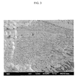
- FIG. 3 is a SEM photograph (23,000-magnification) of the CaSi 2 -Cu-Al negative active material prepared according to Example 1.
- the structure of the Ca 2 Si-Cu-Al negative active material, as shown in FIG. 3 has a lamellar structure in which the needle-structured intermetallic compound (Si-Ca) and the plate-structured metal matrix (Cu-Al) are disposed alternatingly with each other.
- the negative active material of Example 1 was prepared at a very low quenching speed, it may be seen from FIG. 3 that the average thicknesses of the intermetallic compound and the metal matrix were 35 nm and 30 nm, respectively, which are very fine.
- the negative active materials according to the present invention have high capacity, long cycle-life, and excellent battery characteristics.
Applications Claiming Priority (1)
| Application Number | Priority Date | Filing Date | Title |
|---|---|---|---|
| KR1020070027776A KR100796664B1 (ko) | 2007-03-21 | 2007-03-21 | 리튬 이차 전지용 음극 활물질 및 이를 포함하는 리튬 이차전지 |
Publications (2)
| Publication Number | Publication Date |
|---|---|
| EP1973183A1 true EP1973183A1 (de) | 2008-09-24 |
| EP1973183B1 EP1973183B1 (de) | 2010-01-20 |
Family
ID=39218791
Family Applications (1)
| Application Number | Title | Priority Date | Filing Date |
|---|---|---|---|
| EP08153062A Expired - Fee Related EP1973183B1 (de) | 2007-03-21 | 2008-03-20 | Negativ-Aktivmaterial für eine wiederaufladbaren Lithiumbatterie und wiederaufladbaren Lithiumbatterie |
Country Status (6)
| Country | Link |
|---|---|
| US (1) | US8835053B2 (de) |
| EP (1) | EP1973183B1 (de) |
| JP (1) | JP5001890B2 (de) |
| KR (1) | KR100796664B1 (de) |
| CN (1) | CN100585920C (de) |
| DE (1) | DE602008000556D1 (de) |
Families Citing this family (28)
| Publication number | Priority date | Publication date | Assignee | Title |
|---|---|---|---|---|
| GB2395059B (en) | 2002-11-05 | 2005-03-16 | Imp College Innovations Ltd | Structured silicon anode |
| GB0601318D0 (en) | 2006-01-23 | 2006-03-01 | Imp Innovations Ltd | Method of etching a silicon-based material |
| GB0601319D0 (en) * | 2006-01-23 | 2006-03-01 | Imp Innovations Ltd | A method of fabricating pillars composed of silicon-based material |
| GB0709165D0 (en) | 2007-05-11 | 2007-06-20 | Nexeon Ltd | A silicon anode for a rechargeable battery |
| JP5343342B2 (ja) * | 2007-06-26 | 2013-11-13 | 大同特殊鋼株式会社 | リチウム二次電池用負極活物質およびリチウム二次電池 |
| GB0713895D0 (en) * | 2007-07-17 | 2007-08-29 | Nexeon Ltd | Production |
| GB0713896D0 (en) * | 2007-07-17 | 2007-08-29 | Nexeon Ltd | Method |
| GB0713898D0 (en) * | 2007-07-17 | 2007-08-29 | Nexeon Ltd | A method of fabricating structured particles composed of silcon or a silicon-based material and their use in lithium rechargeable batteries |
| GB2464158B (en) | 2008-10-10 | 2011-04-20 | Nexeon Ltd | A method of fabricating structured particles composed of silicon or a silicon-based material and their use in lithium rechargeable batteries |
| GB2464157B (en) | 2008-10-10 | 2010-09-01 | Nexeon Ltd | A method of fabricating structured particles composed of silicon or a silicon-based material |
| GB2470056B (en) * | 2009-05-07 | 2013-09-11 | Nexeon Ltd | A method of making silicon anode material for rechargeable cells |
| US9853292B2 (en) | 2009-05-11 | 2017-12-26 | Nexeon Limited | Electrode composition for a secondary battery cell |
| GB2470190B (en) | 2009-05-11 | 2011-07-13 | Nexeon Ltd | A binder for lithium ion rechargeable battery cells |
| GB2495951B (en) * | 2011-10-26 | 2014-07-16 | Nexeon Ltd | A composition for a secondary battery cell |
| KR101702987B1 (ko) * | 2009-11-04 | 2017-02-23 | 삼성에스디아이 주식회사 | 리튬 이차 전지용 음극 및 이를 포함하는 리튬 이차 전지 |
| GB201005979D0 (en) | 2010-04-09 | 2010-05-26 | Nexeon Ltd | A method of fabricating structured particles composed of silicon or a silicon-based material and their use in lithium rechargeable batteries |
| GB201009519D0 (en) | 2010-06-07 | 2010-07-21 | Nexeon Ltd | An additive for lithium ion rechargeable battery cells |
| GB201014707D0 (en) | 2010-09-03 | 2010-10-20 | Nexeon Ltd | Electroactive material |
| GB201014706D0 (en) | 2010-09-03 | 2010-10-20 | Nexeon Ltd | Porous electroactive material |
| JP5678937B2 (ja) * | 2011-09-16 | 2015-03-04 | 株式会社豊田中央研究所 | リチウム二次電池用電極材、その製造方法、およびそれを備えるリチウム二次電池 |
| US9373839B2 (en) * | 2011-12-13 | 2016-06-21 | Samsung Sdi Co., Ltd. | Negative electrode active material and secondary battery including the same |
| KR101385602B1 (ko) * | 2011-12-14 | 2014-04-21 | 엠케이전자 주식회사 | 이차 전지용 음극 활물질 및 그 제조 방법 |
| KR101403498B1 (ko) * | 2012-01-31 | 2014-06-11 | 엠케이전자 주식회사 | 이차 전지용 음극 활물질 및 이를 포함하는 이차 전지 |
| JP5831407B2 (ja) * | 2012-09-06 | 2015-12-09 | 信越化学工業株式会社 | リチウムイオン電池用負極材 |
| US20140203207A1 (en) * | 2013-01-22 | 2014-07-24 | Mk Electron Co., Ltd. | Anode active material for secondary battery and method of manufacturing the same |
| JPWO2015064633A1 (ja) | 2013-10-30 | 2017-03-09 | 古河電気工業株式会社 | 負極活物質及びその製造方法並びにそれを用いた負極及び非水電解質二次電池 |
| KR20150074905A (ko) * | 2013-12-24 | 2015-07-02 | 일진전기 주식회사 | 리튬 이차 전지용 음극 활물질 |
| JP2016066418A (ja) * | 2014-09-22 | 2016-04-28 | 新日鐵住金株式会社 | 電極活物質材料、電極、電池、及び、電極活物質材料の製造方法 |
Citations (3)
| Publication number | Priority date | Publication date | Assignee | Title |
|---|---|---|---|---|
| JP2003257417A (ja) * | 2002-02-28 | 2003-09-12 | Nippon Mining & Metals Co Ltd | リチウムイオン2次電池用負極 |
| JP2003272613A (ja) | 2002-03-15 | 2003-09-26 | Toshiba Corp | 非水電解質二次電池用負極材料及び非水電解質二次電池 |
| WO2004086539A1 (en) | 2003-03-26 | 2004-10-07 | Canon Kabushiki Kaisha | Electrode material for lithium secondary battery and electrode structure having the electrode material |
Family Cites Families (46)
| Publication number | Priority date | Publication date | Assignee | Title |
|---|---|---|---|---|
| JPS5920971A (ja) | 1982-07-26 | 1984-02-02 | Sanyo Electric Co Ltd | 有機電解液二次電池 |
| US5951793A (en) * | 1995-07-12 | 1999-09-14 | The Furukawa Electric Co., Ltd. | Ni-Ti-Pd superelastic alloy material, its manufacturing method, and orthodontic archwire made of this alloy material |
| KR100366978B1 (ko) | 1998-09-08 | 2003-01-09 | 마츠시타 덴끼 산교 가부시키가이샤 | 비수전해질 이차전지용 음극재료와 그 제조방법 |
| JP3620703B2 (ja) | 1998-09-18 | 2005-02-16 | キヤノン株式会社 | 二次電池用負極電極材、電極構造体、二次電池、及びこれらの製造方法 |
| ATE467914T1 (de) | 1998-09-18 | 2010-05-15 | Canon Kk | Elektrodenmaterial für den negativen pol einer lithiumsekundärzelle, elektrodenstruktur die dieses verwendet, lithiumsekundärzelle mit dieser struktur und verfahren zur herstellung der zelle und der struktur |
| JP4056183B2 (ja) | 1999-09-24 | 2008-03-05 | 松下電器産業株式会社 | 非水電解質二次電池用負極活物質および非水電解質二次電池 |
| EP1043789B1 (de) * | 1998-10-22 | 2013-01-23 | Panasonic Corporation | Sekundärzelle mit nichtwässrigem elektrolyten |
| KR100280997B1 (ko) | 1998-11-25 | 2001-03-02 | 김순택 | 리튬 이온 전지용 음극 활물질 및 그 제조 방법 |
| US6428933B1 (en) | 1999-04-01 | 2002-08-06 | 3M Innovative Properties Company | Lithium ion batteries with improved resistance to sustained self-heating |
| JP2001015102A (ja) | 1999-07-01 | 2001-01-19 | Matsushita Electric Ind Co Ltd | 非水電解質二次電池およびその製造法 |
| KR100529069B1 (ko) | 1999-12-08 | 2005-11-16 | 삼성에스디아이 주식회사 | 리튬 이차 전지용 음극 활물질 및 그의 제조 방법 |
| KR100350535B1 (ko) | 1999-12-10 | 2002-08-28 | 삼성에스디아이 주식회사 | 리튬 이차 전지용 음극 활물질 및 그의 제조 방법 |
| US6664004B2 (en) | 2000-01-13 | 2003-12-16 | 3M Innovative Properties Company | Electrode compositions having improved cycling behavior |
| US6699336B2 (en) | 2000-01-13 | 2004-03-02 | 3M Innovative Properties Company | Amorphous electrode compositions |
| JP2002093415A (ja) | 2000-09-18 | 2002-03-29 | Nichia Chem Ind Ltd | 非水系リチウム二次電池用複合炭素材料及びその合成方法 |
| US6569194B1 (en) * | 2000-12-28 | 2003-05-27 | Advanced Cardiovascular Systems, Inc. | Thermoelastic and superelastic Ni-Ti-W alloy |
| JP3533664B2 (ja) * | 2001-06-27 | 2004-05-31 | ソニー株式会社 | 負極材料およびそれを用いた電池 |
| KR100435180B1 (ko) * | 2001-09-28 | 2004-06-11 | 가부시끼가이샤 도시바 | 비수전해질 전지용 음극 재료, 음극, 비수전해질 전지 및비수전해질 전지용 음극 재료의 제조 방법 |
| CN1419303A (zh) | 2001-09-28 | 2003-05-21 | 株式会社东芝 | 非水电解质电池用负极材料及其制造方法、负极及电池 |
| JP2004006206A (ja) | 2001-09-28 | 2004-01-08 | Toshiba Corp | 非水電解質電池用負極材料、負極、非水電解質電池及び非水電解質電池用負極材料の製造方法 |
| JP4701579B2 (ja) | 2002-01-23 | 2011-06-15 | 日本電気株式会社 | 二次電池用負極 |
| JP2004071542A (ja) * | 2002-06-14 | 2004-03-04 | Japan Storage Battery Co Ltd | 負極活物質、それを用いた負極、それを用いた非水電解質電池、ならびに負極活物質の製造方法 |
| JP4069710B2 (ja) | 2002-09-03 | 2008-04-02 | 住友金属工業株式会社 | リチウムイオン二次電池用負極材料およびその製造方法ならびにリチウムイオン二次電池 |
| US7169328B2 (en) | 2003-01-17 | 2007-01-30 | T/J Technologies, Inc. | Multiphase nanocomposite material and method for its manufacture |
| JP2004296412A (ja) | 2003-02-07 | 2004-10-21 | Mitsui Mining & Smelting Co Ltd | 非水電解液二次電池用負極活物質の製造方法 |
| TWI254473B (en) * | 2003-03-26 | 2006-05-01 | Canon Kk | Electrode material for lithium secondary battery, electrode structure comprising the electrode material and secondary battery comprising the electrode structure |
| JP4464173B2 (ja) | 2003-03-26 | 2010-05-19 | キヤノン株式会社 | リチウム二次電池用の電極材料、該電極材料を有する電極構造体、及び該電極構造体を有する二次電池 |
| KR100570637B1 (ko) | 2003-05-21 | 2006-04-12 | 삼성에스디아이 주식회사 | 리튬 이차 전지용 음극 활물질 및 그의 제조 방법 |
| JP2005011650A (ja) | 2003-06-18 | 2005-01-13 | Sony Corp | 負極材料およびそれを用いた電池 |
| US7498100B2 (en) * | 2003-08-08 | 2009-03-03 | 3M Innovative Properties Company | Multi-phase, silicon-containing electrode for a lithium-ion battery |
| JP4029291B2 (ja) | 2003-09-02 | 2008-01-09 | 福田金属箔粉工業株式会社 | リチウム二次電池用負極材料及びその製造方法 |
| JP4378437B2 (ja) | 2003-09-05 | 2009-12-09 | 眞 佐々木 | リチウム二次電池用負極材料およびリチウム二次電池 |
| JP4703110B2 (ja) | 2003-09-26 | 2011-06-15 | 株式会社東芝 | 非水電解質二次電池用負極材料、非水電解質二次電池用負極及び非水電解質二次電池 |
| US7223498B2 (en) * | 2003-10-09 | 2007-05-29 | Samsung Sdi Co., Ltd. | Electrode for a lithium secondary battery and a lithium secondary battery comprising the same |
| JP3929429B2 (ja) | 2003-10-09 | 2007-06-13 | 三星エスディアイ株式会社 | リチウム二次電池用電極及びリチウム二次電池 |
| JP3746501B2 (ja) | 2003-10-09 | 2006-02-15 | 三星エスディアイ株式会社 | リチウム二次電池用電極材料及びリチウム二次電池及びリチウム二次電池用電極材料の製造方法 |
| US7432014B2 (en) * | 2003-11-05 | 2008-10-07 | Sony Corporation | Anode and battery |
| JP4345643B2 (ja) | 2003-12-15 | 2009-10-14 | 日本電気株式会社 | 二次電池 |
| KR100578872B1 (ko) | 2004-03-08 | 2006-05-11 | 삼성에스디아이 주식회사 | 리튬 이차 전지용 음극 활물질, 그의 제조 방법 및 그를포함하는 리튬 이차 전지 |
| US8389163B2 (en) | 2004-03-16 | 2013-03-05 | Panasonic Corporation | Lithium secondary battery containing organic peroxide in non-aqueous electrolyte, positive electrode, or negative electrode |
| JP4077423B2 (ja) | 2004-03-31 | 2008-04-16 | 株式会社東芝 | 非水電解質二次電池 |
| KR100591792B1 (ko) | 2004-06-16 | 2006-06-26 | 경상대학교산학협력단 | 전지용 집전체-양극 일체형 초탄성 금속-금속황화물 소자 |
| JP4646612B2 (ja) | 2004-12-08 | 2011-03-09 | パナソニック株式会社 | 非水電解質二次電池用負極およびその製造法ならびに非水電解質二次電池 |
| US20060147802A1 (en) * | 2005-01-05 | 2006-07-06 | Kiyotaka Yasuda | Anode for nonaqueous secondary battery, process of producing the anode, and nonaqueous secondary battery |
| KR100949330B1 (ko) * | 2005-11-29 | 2010-03-26 | 삼성에스디아이 주식회사 | 리튬 이차 전지용 음극 활물질 및 그를 포함하는 리튬 이차전지 |
| KR100796687B1 (ko) | 2005-11-30 | 2008-01-21 | 삼성에스디아이 주식회사 | 리튬 이차 전지용 활물질, 이의 제조방법 및 이를 포함하는 리튬 이차 전지 |
-
2007
- 2007-03-21 KR KR1020070027776A patent/KR100796664B1/ko active IP Right Grant
-
2008
- 2008-03-18 US US12/050,864 patent/US8835053B2/en not_active Expired - Fee Related
- 2008-03-20 DE DE602008000556T patent/DE602008000556D1/de active Active
- 2008-03-20 EP EP08153062A patent/EP1973183B1/de not_active Expired - Fee Related
- 2008-03-20 CN CN200810086769A patent/CN100585920C/zh not_active Expired - Fee Related
- 2008-03-21 JP JP2008073437A patent/JP5001890B2/ja not_active Expired - Fee Related
Patent Citations (3)
| Publication number | Priority date | Publication date | Assignee | Title |
|---|---|---|---|---|
| JP2003257417A (ja) * | 2002-02-28 | 2003-09-12 | Nippon Mining & Metals Co Ltd | リチウムイオン2次電池用負極 |
| JP2003272613A (ja) | 2002-03-15 | 2003-09-26 | Toshiba Corp | 非水電解質二次電池用負極材料及び非水電解質二次電池 |
| WO2004086539A1 (en) | 2003-03-26 | 2004-10-07 | Canon Kabushiki Kaisha | Electrode material for lithium secondary battery and electrode structure having the electrode material |
Also Published As
| Publication number | Publication date |
|---|---|
| CN101271975A (zh) | 2008-09-24 |
| DE602008000556D1 (de) | 2010-03-11 |
| EP1973183B1 (de) | 2010-01-20 |
| US8835053B2 (en) | 2014-09-16 |
| CN100585920C (zh) | 2010-01-27 |
| KR100796664B1 (ko) | 2008-01-22 |
| JP5001890B2 (ja) | 2012-08-15 |
| JP2008235276A (ja) | 2008-10-02 |
| US20080233480A1 (en) | 2008-09-25 |
Similar Documents
| Publication | Publication Date | Title |
|---|---|---|
| EP1973183B1 (de) | Negativ-Aktivmaterial für eine wiederaufladbaren Lithiumbatterie und wiederaufladbaren Lithiumbatterie | |
| US8574764B2 (en) | Negative active material including silicon active particles surrounded by copper, aluminum and tin metal matrix and rechargeable lithium battery including the same | |
| US9284630B2 (en) | Negative active material including Si active metal grains and Cu—Al metal matrix surrounding Si active metal grains and rechargeable lithium battery including negative active material | |
| US20080233479A1 (en) | Negative active material for rechargeable lithium battery and rechargeable lithium battery including same | |
| EP1923937B1 (de) | Elektrode für eine wiederaufladbare Lithiumbatterie und daraus hergestellte wiederaufladbare Lithiumbatterie | |
| US8173303B2 (en) | Lithium secondary battery | |
| US8377592B2 (en) | Negative active material for rechargeable lithium battery, and method of preparing the same | |
| EP1923352B1 (de) | Negativ-Aktivmaterial für eine wiederaufladbare Lithiumbatterie, Herstellungsverfahren desselben und wiederaufladbare Lithiumbatterie dieses enthaltend | |
| EP2065955B1 (de) | Herstellungsverfahren für ein Anodenmaterial für wiederaufladbare Lithiumbatterien | |
| US20090053607A1 (en) | Electrode for rechargeable lithium battery and rechargeable lithium battery including same | |
| US20080118846A1 (en) | Rechargeable lithium battery | |
| US20070190415A1 (en) | Negative active material for rechargeable lithium battery, method of preparing same, and rechargeable lithium battery including same | |
| US9209481B2 (en) | Rechargeable battery with an electrode assembly having a polymer region | |
| US8835051B2 (en) | Negative active material for rechargeable lithium battery, method for preparing same, and rechargeable lithium battery including same | |
| KR100529091B1 (ko) | 리튬 이차 전지용 전극 및 이를 포함하는 리튬 이차 전지 | |
| KR20080094214A (ko) | 리튬 이차 전지용 음극 활물질의 제조 방법 및 그 방법에따라 제조된 음극 활물질을 포함하는 리튬 이차 전지 |
Legal Events
| Date | Code | Title | Description |
|---|---|---|---|
| PUAI | Public reference made under article 153(3) epc to a published international application that has entered the european phase |
Free format text: ORIGINAL CODE: 0009012 |
|
| 17P | Request for examination filed |
Effective date: 20080320 |
|
| AK | Designated contracting states |
Kind code of ref document: A1 Designated state(s): AT BE BG CH CY CZ DE DK EE ES FI FR GB GR HR HU IE IS IT LI LT LU LV MC MT NL NO PL PT RO SE SI SK TR |
|
| AX | Request for extension of the european patent |
Extension state: AL BA MK RS |
|
| RIN1 | Information on inventor provided before grant (corrected) |
Inventor name: LEE, SANG-MIN Inventor name: JEONG, GOO-JIN Inventor name: KANG, YONG-MOOK Inventor name: CHOI, WAN-UK Inventor name: SUNG, MIN-SEOK Inventor name: KIM, SUNG-SOO |
|
| AKX | Designation fees paid |
Designated state(s): DE FR GB |
|
| GRAP | Despatch of communication of intention to grant a patent |
Free format text: ORIGINAL CODE: EPIDOSNIGR1 |
|
| GRAS | Grant fee paid |
Free format text: ORIGINAL CODE: EPIDOSNIGR3 |
|
| GRAA | (expected) grant |
Free format text: ORIGINAL CODE: 0009210 |
|
| AK | Designated contracting states |
Kind code of ref document: B1 Designated state(s): DE FR GB |
|
| REG | Reference to a national code |
Ref country code: GB Ref legal event code: FG4D |
|
| REF | Corresponds to: |
Ref document number: 602008000556 Country of ref document: DE Date of ref document: 20100311 Kind code of ref document: P |
|
| PLBE | No opposition filed within time limit |
Free format text: ORIGINAL CODE: 0009261 |
|
| STAA | Information on the status of an ep patent application or granted ep patent |
Free format text: STATUS: NO OPPOSITION FILED WITHIN TIME LIMIT |
|
| 26N | No opposition filed |
Effective date: 20101021 |
|
| REG | Reference to a national code |
Ref country code: FR Ref legal event code: PLFP Year of fee payment: 9 |
|
| REG | Reference to a national code |
Ref country code: FR Ref legal event code: PLFP Year of fee payment: 10 |
|
| REG | Reference to a national code |
Ref country code: FR Ref legal event code: PLFP Year of fee payment: 11 |
|
| PGFP | Annual fee paid to national office [announced via postgrant information from national office to epo] |
Ref country code: GB Payment date: 20200311 Year of fee payment: 13 Ref country code: DE Payment date: 20200310 Year of fee payment: 13 |
|
| PGFP | Annual fee paid to national office [announced via postgrant information from national office to epo] |
Ref country code: FR Payment date: 20200227 Year of fee payment: 13 |
|
| REG | Reference to a national code |
Ref country code: DE Ref legal event code: R119 Ref document number: 602008000556 Country of ref document: DE |
|
| GBPC | Gb: european patent ceased through non-payment of renewal fee |
Effective date: 20210320 |
|
| PG25 | Lapsed in a contracting state [announced via postgrant information from national office to epo] |
Ref country code: DE Free format text: LAPSE BECAUSE OF NON-PAYMENT OF DUE FEES Effective date: 20211001 Ref country code: FR Free format text: LAPSE BECAUSE OF NON-PAYMENT OF DUE FEES Effective date: 20210331 Ref country code: GB Free format text: LAPSE BECAUSE OF NON-PAYMENT OF DUE FEES Effective date: 20210320 |