EP1970600A2 - Automatikgetriebe und Verfahren zur Verhinderung von dessen Überdrehung - Google Patents
Automatikgetriebe und Verfahren zur Verhinderung von dessen Überdrehung Download PDFInfo
- Publication number
- EP1970600A2 EP1970600A2 EP08002971A EP08002971A EP1970600A2 EP 1970600 A2 EP1970600 A2 EP 1970600A2 EP 08002971 A EP08002971 A EP 08002971A EP 08002971 A EP08002971 A EP 08002971A EP 1970600 A2 EP1970600 A2 EP 1970600A2
- Authority
- EP
- European Patent Office
- Prior art keywords
- rotational speed
- rotational
- elements
- predetermined
- input
- Prior art date
- Legal status (The legal status is an assumption and is not a legal conclusion. Google has not performed a legal analysis and makes no representation as to the accuracy of the status listed.)
- Granted
Links
- 230000005540 biological transmission Effects 0.000 title claims abstract description 55
- 238000000034 method Methods 0.000 title claims description 14
- 238000001514 detection method Methods 0.000 claims description 17
- 238000010586 diagram Methods 0.000 description 14
- 230000001276 controlling effect Effects 0.000 description 8
- 230000007257 malfunction Effects 0.000 description 8
- 230000001105 regulatory effect Effects 0.000 description 8
- 230000004044 response Effects 0.000 description 4
- 101100096185 Alternaria solani sol6 gene Proteins 0.000 description 3
- 101150032095 SOL3 gene Proteins 0.000 description 3
- 230000007246 mechanism Effects 0.000 description 3
- 230000007935 neutral effect Effects 0.000 description 3
- 101100096184 Alternaria solani sol5 gene Proteins 0.000 description 2
- 101100168642 Arabidopsis thaliana CRN gene Proteins 0.000 description 2
- 101100045632 Arabidopsis thaliana TCX2 gene Proteins 0.000 description 2
- 101100045633 Arabidopsis thaliana TCX3 gene Proteins 0.000 description 2
- 101150037491 SOL1 gene Proteins 0.000 description 2
- 230000008859 change Effects 0.000 description 2
- 101150103732 sol2 gene Proteins 0.000 description 2
- 101150090449 sol4 gene Proteins 0.000 description 2
- 230000002159 abnormal effect Effects 0.000 description 1
- 230000005856 abnormality Effects 0.000 description 1
- 230000000994 depressogenic effect Effects 0.000 description 1
- 239000000446 fuel Substances 0.000 description 1
- 238000002347 injection Methods 0.000 description 1
- 239000007924 injection Substances 0.000 description 1
- 238000012986 modification Methods 0.000 description 1
- 230000004048 modification Effects 0.000 description 1
- 230000009467 reduction Effects 0.000 description 1
Images




Classifications
-
- F—MECHANICAL ENGINEERING; LIGHTING; HEATING; WEAPONS; BLASTING
- F16—ENGINEERING ELEMENTS AND UNITS; GENERAL MEASURES FOR PRODUCING AND MAINTAINING EFFECTIVE FUNCTIONING OF MACHINES OR INSTALLATIONS; THERMAL INSULATION IN GENERAL
- F16H—GEARING
- F16H61/00—Control functions within control units of change-speed- or reversing-gearings for conveying rotary motion ; Control of exclusively fluid gearing, friction gearing, gearings with endless flexible members or other particular types of gearing
- F16H61/12—Detecting malfunction or potential malfunction, e.g. fail safe ; Circumventing or fixing failures
-
- F—MECHANICAL ENGINEERING; LIGHTING; HEATING; WEAPONS; BLASTING
- F16—ENGINEERING ELEMENTS AND UNITS; GENERAL MEASURES FOR PRODUCING AND MAINTAINING EFFECTIVE FUNCTIONING OF MACHINES OR INSTALLATIONS; THERMAL INSULATION IN GENERAL
- F16H—GEARING
- F16H61/00—Control functions within control units of change-speed- or reversing-gearings for conveying rotary motion ; Control of exclusively fluid gearing, friction gearing, gearings with endless flexible members or other particular types of gearing
- F16H61/18—Preventing unintentional or unsafe shift, e.g. preventing manual shift from highest gear to reverse gear
-
- F—MECHANICAL ENGINEERING; LIGHTING; HEATING; WEAPONS; BLASTING
- F16—ENGINEERING ELEMENTS AND UNITS; GENERAL MEASURES FOR PRODUCING AND MAINTAINING EFFECTIVE FUNCTIONING OF MACHINES OR INSTALLATIONS; THERMAL INSULATION IN GENERAL
- F16H—GEARING
- F16H61/00—Control functions within control units of change-speed- or reversing-gearings for conveying rotary motion ; Control of exclusively fluid gearing, friction gearing, gearings with endless flexible members or other particular types of gearing
-
- F—MECHANICAL ENGINEERING; LIGHTING; HEATING; WEAPONS; BLASTING
- F16—ENGINEERING ELEMENTS AND UNITS; GENERAL MEASURES FOR PRODUCING AND MAINTAINING EFFECTIVE FUNCTIONING OF MACHINES OR INSTALLATIONS; THERMAL INSULATION IN GENERAL
- F16H—GEARING
- F16H61/00—Control functions within control units of change-speed- or reversing-gearings for conveying rotary motion ; Control of exclusively fluid gearing, friction gearing, gearings with endless flexible members or other particular types of gearing
- F16H61/16—Inhibiting or initiating shift during unfavourable conditions , e.g. preventing forward-reverse shift at high vehicle speed, preventing engine overspeed
-
- F—MECHANICAL ENGINEERING; LIGHTING; HEATING; WEAPONS; BLASTING
- F16—ENGINEERING ELEMENTS AND UNITS; GENERAL MEASURES FOR PRODUCING AND MAINTAINING EFFECTIVE FUNCTIONING OF MACHINES OR INSTALLATIONS; THERMAL INSULATION IN GENERAL
- F16H—GEARING
- F16H59/00—Control inputs to control units of change-speed- or reversing-gearings for conveying rotary motion
- F16H59/36—Inputs being a function of speed
- F16H59/38—Inputs being a function of speed of gearing elements
- F16H2059/385—Turbine speed
-
- F—MECHANICAL ENGINEERING; LIGHTING; HEATING; WEAPONS; BLASTING
- F16—ENGINEERING ELEMENTS AND UNITS; GENERAL MEASURES FOR PRODUCING AND MAINTAINING EFFECTIVE FUNCTIONING OF MACHINES OR INSTALLATIONS; THERMAL INSULATION IN GENERAL
- F16H—GEARING
- F16H61/00—Control functions within control units of change-speed- or reversing-gearings for conveying rotary motion ; Control of exclusively fluid gearing, friction gearing, gearings with endless flexible members or other particular types of gearing
- F16H61/12—Detecting malfunction or potential malfunction, e.g. fail safe ; Circumventing or fixing failures
- F16H2061/1208—Detecting malfunction or potential malfunction, e.g. fail safe ; Circumventing or fixing failures with diagnostic check cycles; Monitoring of failures
-
- F—MECHANICAL ENGINEERING; LIGHTING; HEATING; WEAPONS; BLASTING
- F16—ENGINEERING ELEMENTS AND UNITS; GENERAL MEASURES FOR PRODUCING AND MAINTAINING EFFECTIVE FUNCTIONING OF MACHINES OR INSTALLATIONS; THERMAL INSULATION IN GENERAL
- F16H—GEARING
- F16H2200/00—Transmissions for multiple ratios
- F16H2200/003—Transmissions for multiple ratios characterised by the number of forward speeds
- F16H2200/0056—Transmissions for multiple ratios characterised by the number of forward speeds the gear ratios comprising seven forward speeds
-
- F—MECHANICAL ENGINEERING; LIGHTING; HEATING; WEAPONS; BLASTING
- F16—ENGINEERING ELEMENTS AND UNITS; GENERAL MEASURES FOR PRODUCING AND MAINTAINING EFFECTIVE FUNCTIONING OF MACHINES OR INSTALLATIONS; THERMAL INSULATION IN GENERAL
- F16H—GEARING
- F16H2200/00—Transmissions for multiple ratios
- F16H2200/20—Transmissions using gears with orbital motion
- F16H2200/2002—Transmissions using gears with orbital motion characterised by the number of sets of orbital gears
- F16H2200/2012—Transmissions using gears with orbital motion characterised by the number of sets of orbital gears with four sets of orbital gears
-
- F—MECHANICAL ENGINEERING; LIGHTING; HEATING; WEAPONS; BLASTING
- F16—ENGINEERING ELEMENTS AND UNITS; GENERAL MEASURES FOR PRODUCING AND MAINTAINING EFFECTIVE FUNCTIONING OF MACHINES OR INSTALLATIONS; THERMAL INSULATION IN GENERAL
- F16H—GEARING
- F16H2200/00—Transmissions for multiple ratios
- F16H2200/20—Transmissions using gears with orbital motion
- F16H2200/203—Transmissions using gears with orbital motion characterised by the engaging friction means not of the freewheel type, e.g. friction clutches or brakes
- F16H2200/2053—Transmissions using gears with orbital motion characterised by the engaging friction means not of the freewheel type, e.g. friction clutches or brakes with nine engaging means
-
- F—MECHANICAL ENGINEERING; LIGHTING; HEATING; WEAPONS; BLASTING
- F16—ENGINEERING ELEMENTS AND UNITS; GENERAL MEASURES FOR PRODUCING AND MAINTAINING EFFECTIVE FUNCTIONING OF MACHINES OR INSTALLATIONS; THERMAL INSULATION IN GENERAL
- F16H—GEARING
- F16H61/00—Control functions within control units of change-speed- or reversing-gearings for conveying rotary motion ; Control of exclusively fluid gearing, friction gearing, gearings with endless flexible members or other particular types of gearing
- F16H61/68—Control functions within control units of change-speed- or reversing-gearings for conveying rotary motion ; Control of exclusively fluid gearing, friction gearing, gearings with endless flexible members or other particular types of gearing specially adapted for stepped gearings
- F16H61/684—Control functions within control units of change-speed- or reversing-gearings for conveying rotary motion ; Control of exclusively fluid gearing, friction gearing, gearings with endless flexible members or other particular types of gearing specially adapted for stepped gearings without interruption of drive
- F16H61/686—Control functions within control units of change-speed- or reversing-gearings for conveying rotary motion ; Control of exclusively fluid gearing, friction gearing, gearings with endless flexible members or other particular types of gearing specially adapted for stepped gearings without interruption of drive with orbital gears
Definitions
- the present invention relates to a control for preventing over-revolution of rotational elements in a multi-speed automatic transmission. More specifically, the present invention relates to an automatic transmission adapted to prevent such over-revolution and a method for carrying out such a control.
- an automatic transmission comprising a plurality of planetary gears disposed between an input shaft and an output shaft and having a plurality of rotational elements, a plurality of frictional elements selectively engaged and released for controlling rotations and connections of the plurality of rotational elements, a controller for controlling engagement and release of the plurality of frictional elements in accordance with instructions so as to realize a plurality of gear positions, the controller including a rotational speed detecting section for detecting a rotational speed of a predetermined one of the plurality of rotational elements, other than the input shaft and the output shaft, and a frictional element release section for releasing all of the frictional elements when it is judged that the rotational speed of the predetermined one of the plurality of rotational elements is higher than a predetermined rotational speed.
- an automatic transmission comprising a plurality of planetary gears disposed between an input shaft and an output shaft and having a plurality of rotational elements, a plurality of frictional elements selectively engaged and released for controlling rotations and connections of the plurality of rotational elements in accordance with instructions so as to realize a plurality of gear positions, rotational speed detecting means for detecting a rotational speed of a predetermined one of the plurality of rotational elements, other than the input shaft and the output shaft, and frictional element release means for releasing all of the plurality of frictional elements when it is judged that the rotational speed of the predetermined one of the plurality of rotational elements is higher than a predetermined speed.
- a method for preventing over-revolution of an automatic transmission including a plurality of planetary gears disposed between an input shaft and an output shaft and having a plurality of rotational elements, and a plurality of frictional elements selectively engaged and released for controlling rotations and connections of the plurality of rotational elements in accordance with instructions so as to realize a plurality of gear positions, the method comprising detecting a rotational speed of a predetermined one of the plurality of rotational elements, other than the input shaft and the output shaft, and releasing all of the plurality of frictional elements when it is judged that the rotational speed of the predetermined one of the plurality of rotational elements is higher than a predetermined rotational speed.
- an automatic transmission is a stepped automatic transmission that provides seven forward speeds and one rearward speed.
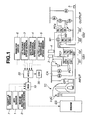
- the driving force of an engine EG is supplied to an input shaft INPUT of the transmission by way of a torque converter TC and outputted from an output shaft OUTPUT after subjected to a change in speed by means of four planetary gears and nine frictional elements.
- an oil pump OP is disposed coaxially with an pump impeller of the torque converter TC and driven to rotate by means of an engine EG to pressurize oil.
- an engine control unit (ECU) 10 for controlling an operating condition of the engine EG
- an automatic transmission control unit (ATCU) 20 for controlling a shift state and so on of the automatic transmission
- a control valve unit (CVU) for controlling an oil pressure for each frictional element on the basis of an output signal of the ATCU 20.
- the ECU 10 and ATCU 20 are connected with each other by way of a CAN communication line or the like so as to hold a sensor information and control information in common by communication.
- an APO sensor 1 for detecting the amount of accelerator pedal operation by a driver
- an engine rotational speed sensor 2 for detecting an engine speed
- a throttle sensor 7 for detecting a throttle opening degree.
- the ECU 10 controls a fuel injection amount and a throttle opening degree on the basis of the engine speed and the amount of accelerator pedal operation for thereby controlling a speed and a torque of the engine EG.
- first turbine speed sensor for detecting a speed of a first carrier PC1
- second turbine speed sensor for detecting a speed of a first ring gear R1
- an inhibiter switch 6 for detecting a sate of shift lever operation by a driver.
- the ATCU 20 selects an optimal gear position based on a vehicle speed V SP and the amount APO of accelerator pedal operation and outputs an instruction for attaining the optimal gear position to the control valve unit CVU. Further, the ATCU 20 calculates a rotational speed of the input shaft INPUT based on detection values of the first turbine speed sensor 3 and the second turbine speed sensor 4. The method for calculating the rotational speed of the input shaft INPUT will be described hereinlater.
- a gear shift mechanism for transmitting rotation of the input shaft INPUT to the output shaft OUTPUT while changing its rotational speed.
- the gear shift mechanism are disposed in the order from the input shaft INPUT side to the output shaft OUTPUT side a first planetary gear set GS1 and a second planetary gear set GS2. Further, there are disposed a plurality of clutches C1, C2 and C3, a plurality of brakes B1, B2, B3 and B4, and a plurality of one-way clutches F1 and F2 to serve as the above-described frictional elements.
- the first planetary gear set GS1 consists of a first planetary gear G1 and a second planetary gear G2.
- the first planetary gear G1 is a single pinion type planetary gear including a first sun gear S1, a first ring gear R1, a first carrier PC1 supporting a first pinion P1 meshed with the both gears S1 and R1.
- the second planetary gear G2 is a single pinion type planetary gear including a second sun gear S2, a second ring gear R2 and a second carrier PC2 supporting a second pinion P2 meshed with the both gear S2 and R2.
- the second planetary gear set GS2 consists of a third planetary gear G3 and a fourth planetary gear 4.
- the third planetary gear G3 is a single pinion type planetary gear including a third sun gear S3, a third ring gear R3 and a third carrier PC3 supporting a third pinion P3 meshed with the both gears S3 and R3.
- the fourth planetary gear G4 is a single pinion type planetary gear including a fourth sun gear S4, a fourth ring gear R4 and a fourth carrier PC4 supporting a fourth pinion P4 meshed with the both gears S4 and R4.
- the input shaft INPUT is connected to the second ring gear R2 and receives a driving force from the engine EG by way of the torque converter TC.
- the output shaft OUTPUT is connected to the third carrier PC3 and outputs a driving force to driving wheels by way of a final gear and so on.
- a first connecting member M1 is a member that integrally connects the first ring gear R1, the second carrier PC2 and the fourth ring gear R4.
- a second connecting member M2 is a member that integrally connects the third ring gear R3 and the fourth carrier PC4.
- a third connecting member M3 is a member that integrally connects the first sun gear S1 and the second sun gear S2.
- the first planetary gear set GS1 is constructed so as to connect the first planetary gear G1 and the second planetary gear G2 by the first connecting member M1 and the third connecting member M3 and is thereby constituted by four rotational elements.
- the second planetary gear set GS2 is constructed so as to connect the third planetary gear G3 and the fourth planetary gear G4 by the second connecting member M2 and is thereby constituted by five rotational elements.
- a torque is inputted from the input shaft INPUT to the second ring gear R2, and the inputted torque is outputted to the second planetary gear set GS2 by way of the first connecting member M1.
- a torque is inputted from the input shaft INPUT directly to the second connecting member M2 and also to the fourth ring gear R4 by way of the first connecting member M1, and the inputted torque is outputted to the output shaft OUTPUT from the third carrier PC3.
- the clutch C1 is an input clutch that selectively connects and disconnects between the third sun gear S3 and the fourth sun gear S4.
- the clutch C2 is a direct clutch that selectively connects and disconnects between the fourth sun gear S4 and the fourth carrier PC4.
- the clutch C3 is an H & LR clutch that selectively connects and disconnects between the third sun gear S3 and the fourth sun gear S4. Further, between the third sun gear S3 and the fourth sun gear S4 is disposed a second one-way clutch F2.
- the H & LR clutch C3 is released and the speed of the fourth sun gear S4 is larger than that of the third sun gear S3, the third sun gear S3 and the fourth sun gear S4 generate independent speeds.
- the third planetary gear G3 and the fourth planetary gear G4 are structured so as to be connected by way of the second connecting member M2 and attain respective gear ratios independently.
- the brake B1 is a front brake for selectively stopping rotation of the first carrier PC1. Further, a first one-way clutch F1 is disposed in parallel with the front brake B1.
- the brake B2 is a low brake for selectively stopping rotation of the third sun gear S3.
- the brake B3 is a 2346 brake for selectively stopping rotation of the third connecting member M3 that connects the first sun gear S1 and the second sun gear S3.
- the brake B4 is a reverse brake for selectively stopping rotation of the fourth carrier PC4.
- the turbine speed is calculated by the following expression (1) based on the rotational speed of the first carrier PC1 that is a detection value of the first turbine speed sensor 3 and the rotational speed of the second carrier PC2 that is a detection value of the second turbine speed sensor 4.
- N Input ⁇ 1 + ⁇ 1 ⁇ ⁇ 2 + ⁇ 2 / ⁇ 1 ⁇ N PC ⁇ 2 - ⁇ 1 ⁇ ⁇ 2 + ⁇ 2 / ⁇ 1 ⁇ N PC ⁇ 1
- N Input , N PC1 , N PC2 , ⁇ 1 and ⁇ 2 indicate the rotational speed of the input shaft INPUT, the rotational speed of the first carrier PC1 and the rotational speed of the second carrier PC2, the tooth ratio of the planetary gear G1 and the tooth ratio of the planetary gear G2.
- the tooth ratios ⁇ 1 , ⁇ 2 are the ratios between the numbers Z R1 , Z R2 of teeth of the ring gears R1, R2 and the numbers Z S1 , Z S2 of teeth of the sung gears S1, S2 as shown by the following expression (2).
- ⁇ 1 Z S ⁇ 1 / Z R ⁇ 1
- ⁇ 2 Z S ⁇ 2 / Z R ⁇ 2
- FIG. 2 is a circuit diagram depicting the hydraulic circuit of the CVU 30.
- the hydraulic circuit is provided with an oil pump OP that is driven by the engine EG to serve as an oil pressure source, a manual valve MV for switching an oil passage for supplying a line pressure PL in response to a shift lever operation by a driver, and a pilot valve PV for reducing the line pressure PL to a predetermined pressure.
- first pressure regulation valve CV1 for regulating the engagement pressure of the low brake B2
- second pressure regulation valve CV2 for regulating the engagement pressure of the input clutch C1
- third pressure regulation valve CV3 for regulating the engagement pressure of the front brake B1
- fourth pressure regulation valve CV4 for regulating the engagement pressure of the H & RL clutch C3
- fifth pressure regulation valve CV5 for regulating the engagement pressure of the 2346 brake B3
- sixth pressure regulation valve CV6 for regulating the engagement pressure of the direct clutch C2.
- a first directional control valve SV1 for selectively communicating only one of the low brake B2 and the input clutch C1 with a corresponding oil supply passage
- a second switch valve SV2 for selectively communicating only one of a D range pressure supply passage and an R range pressure supply passage with the direct clutch C2
- a third directional control valve SV3 for switching the oil pressure to be supplied to the reverse brake B4 between the oil pressure supplied from the sixth pressure regulating valve CV6 and the R range pressure
- a fourth directional control valve SV4 for switching a passage to which the pressure outputted from the sixth pressure-regulating valve CV6 is supplied between the oil passage 123 and the oil passage 122.
- a first solenoid valve SOL1 that outputs a pressure regulation signal to the first pressure regulation valve CV1
- a second solenoid valve SOL2 that outputs a pressure regulation signal to the second pressure regulation valve CV2
- a third solenoid valve SOL3 that outputs a pressure regulation signal to the third pressure regulation valve SOL3
- a fourth solenoid valve SOL4 that outputs a pressure regulation signal to the fourth pressure regulation valve CV4
- a fifth solenoid valve SOL5 that outputs a pressure regulation signal to the fifth pressure regulation valve CV5
- a sixth solenoid valve SOL6 that outputs a pressure regulation signal to the sixth pressure regulation valve SOL6
- a seventh solenoid valve SOL7 that outputs a control signal to the first directional control valve SV1 and the third directional control valve SV3, on the basis of control signals from the ATCU 20.
- the discharge pressure of the oil pump OP that is driven by the engine EG is regulated to the line pressure PL and thereafter supplied to oil passages 101 and 102.
- an oil passage 101a that is connected to the manual valve MV operated in relation to a shift lever operation by a vehicle driver, an oil passage 101b for supply of an original pressure for creating the engagement pressure of the front brake B1 and an oil passage 101c for supply of an original pressure for creating the engagement pressure of the H&LR clutch 3.
- an oil passage 105 To the manual valve MV are connected an oil passage 105, and an oil passage 106 for supplying to the reverse brake B4 an R range pressure for selection of an R range at rearward running, one of the oil passages 105 and 106 being selectively communicated with the manual valve MV in response to a shift lever operation.
- an oil passage 105a for supply of an original pressure for creating the engagement pressure of the low brake B2
- an oil passage 105b for supply of an original pressure for creating the engagement pressure of the input clutch C1
- an oil passage 105c for supply of an original pressure for creating the engagement pressure of the 2346 brake B3
- an oil passage 105d for supply of an original pressure for creating the engagement pressure of the direct clutch C2
- an oil passage 105e for supply of a control pressure of the second directional control valve SV2.
- an oil passage 106a for supply of the control pressure of the second directional control valve SV2, an oil passage 106b for supply of an original pressure for creating the engagement pressure of the direct clutch C2 and an oil passage 106c for supply of the engagement pressure of the reverse brake B4.
- the oil passage 103 is connected with an oil passage 103a for supplying the pilot pressure to the first solenoid valve SOL1, an oil passage 103b for supplying the pilot pressure to the second solenoid valve SOL2, an oil passage 103c for supplying the pilot pressure to the third solenoid valve SOL3, an oil passage 103d for supplying the pilot pressure to the fourth solenoid valve SOL4, an oil passage 103e for supplying the pilot pressure to the fifth solenoid valve SOL5, an oil passage 103f for supplying the pilot pressure to the sixth solenoid valve SOL6 and an oil passage 103g for supplying the pilot pressure to the seventh solenoid valve SOL7.
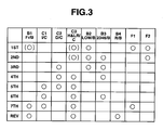
- FIG. 3 is a table showing whether the frictional elements are engaged or released at respective gear positions, wherein ⁇ indicates that the frictional element is engaged and ( ⁇ ) indicates that the frictional element is engaged when a gear position at which engine brake will be operated is selected.
- FIG. 4 is a collinear diagram showing rotational states of rotational elements for respective gear positions.
- first speed 1ST the low brake B2, the first one-way clutch F1 and second one-way clutch F2 are engaged. Further, when engine brake is operating, the front brake B1 and the H&L clutch C3 are further engaged.
- the first carrier PC1 With the first one-way clutch F1 engaged, the first carrier PC1 is held stationary relative to the transmission case TC, i.e., held against rotation.
- the rotation inputted from the input shaft INPUT to the second ring gear R2 is reduced in speed by the first planetary gear set GS1 and outputted from the first connection member M1 to the fourth ring gear R4.
- the third sun gear S3 and the fourth sun gear S4 are held stationary relative to the transmission case TC, i.e., held against rotation. Rotation inputted to the fourth ring gear R4 is thus reduced in speed by the second planetary gear set GS2 and outputted from the third carrier PC3.
- the rotation of the input shaft INPUT is reduced in speed by the first planetary gear set GS1 and further by the second planetary gear set GS2 and outputted from the output shaft OUTPUT.
- the low brake B2, the 2346 brake B3 and the second one-way clutch F2 are engaged. Further, at the time of engine brake being operated, the H&L clutch C3 is further engaged.
- the first sun gear S1 and the second sun gear S2 are held stationary relative to the transmission case TC, i.e., held against rotation so that rotation inputted from the input shaft INPUT to the second ring gear R2 is reduced in speed only by the second planetary gear G2 and the rotation thus reduced in speed is outputted from the first connecting member M1 to the fourth ring gear R4.
- the third sun gear S3 and the fourth sun gear S4 are held stationary relative to the transmission case TC, i.e., held against rotation so that the rotation inputted to the fourth ring gear R4 is reduced in speed by the second planetary gear set GS2 and outputted from the third carrier PC3.
- the rotation of the input shaft INPUT is reduced in speed by the first planetary gear set GS1 and further by the second planetary gear set GS2 and outputted from the output shaft OUTPUT.
- the low brake B2, the 2346 brake B3 and the direct clutch C2 are engaged.
- the first sun gear S1 and the second sun gear S2 are held stationary relative to the transmission case TC, i.e., held against rotation so that the rotation inputted from the input shaft INPUT to the second ring gear R2 is reduced in speed by the second planetary gear G2 and the rotation thus reduced in speed is outputted from the first connecting member M1 to the fourth ring gear R4.
- the fourth planetary gear G4 is caused to rotate as an integral unit. Accordingly, the fourth planetary gear G4 participates in torque transmission but not in reduction in speed.
- the third sun gear S3 is held stationary relative to the transmission case TC, i.e., held against rotation so that the rotation inputted from the fourth carrier C4 that rotates together with the fourth ring gear R4 to the third ring gear R3 by way of the second connecting member M2 is reduced in speed by the third planetary gear G3 and outputted from the third carrier PC3.
- the rotation of the input shaft INPUT is reduced in speed by the first gear set GS1, then further reduced in speed by the third planetary gear G3 of the second planetary gear set GS2 and outputted from the output shaft OUTPUT.
- the first sun gear S1 and the second sun gear S2 are held stationary relative to the transmission case TC, i.e., held against rotation so that the rotation inputted from the input shaft INPUT to the second ring gear R2 is reduced in speed only by the second planetary gear G2 and the rotation thus reduced in speed is outputted from the first connecting member M1 to the fourth ring gear R4.
- the second planetary gear set GS2 is rotated as an integral unit so that the rotation inputted to the fourth ring gear R4 is outputted from the third carrier PC3 as it is.
- the rotation of the input shaft INPUT is reduced in speed by the first planetary gear set GS1 and outputted from the output shaft OUTPUT without being reduced in speed by the second planetary gear set GS2.
- the rotation of the input shaft INPUT is outputted from the output shaft OUTPUT without being reduced in speed by the first planetary gear set GS1 and the second planetary gear set GS2.
- the rotation of the input shaft INPUT is inputted to the second ring gear R2 while at the same time being inputted directly to the second connecting member M2.
- the first sun gear S1 and the second sun gear S2 are held stationary relative to the transmission case TC, i.e., held against rotation CA so that the rotation of the input shaft INPUT is reduced in speed by the second planetary gear G2 and outputted from the first connecting member M1 to the fourth ring gear R4.
- the third sun gear S3 and the fourth sun gear S4 are rotated together as an integral unit so that the second planetary gear set GS2 outputs from the third carrier PC3 rotation that is determined by the rotation of the fourth ring gear R4 and the rotation of the second connecting member M2.
- part of the rotation of the input shaft INPUT is reduced in speed at the first planetary gear set GS1 while on the other hand being increased in speed at the second planetary gear set GS2 and outputted from the output shaft OUTPUT.
- the input clutch C1, the H&LR clutch C3, the first one-way clutch F1 and the front brake B1 are engaged.
- the rotation of the input shaft INPUT is inputted to the second ring gear R2 while at the same time being inputted directly to the second connecting member M2.
- the first carrier PC1 is held stationary relative to the transmission case TC, i.e., held against rotation so that the rotation of the input shaft INPUT is reduced in speed by the first planetary gear set GS1 and the rotation thus reduced in speed is outputted from the first connecting member M1 to the fourth ring gear R4.
- the third sun gear S3 and the fourth sun gear S4 are rotated together as an integral unit so that the second planetary gear set GS2 outputs from the third carrier PC3 rotation that is determined by the rotation of the fourth ring gear R4 and the rotation of the second connecting member M2.
- the rotation of the input shaft INPUT is partly reduced by the first planetary gear set GS1 and partly increased by the second planetary gear set GS2 and outputted from the output shaft OUTPUT.
- the first carrier PC1 With the front brake B1 engaged, the first carrier PC1 is held stationary relative to the transmission case TC, i.e., held against rotation so that the rotation of the input shaft INPUT is reduced in speed by the first planetary gear set GS1 and the rotation thus reduced in speed is outputted from the first connecting member M1 to the fourth ring gear R4.
- the third sun gear S3 and the fourth sun gear S4 are rotated together as an integral unit, and with the reverse brake B4 engaged, the second connecting member M2 is held stationary relative to the transmission case TC, i.e., held against rotation.
- the rotation of the fourth ring gear R4 is transmitted while being reversed in the direction rotation through the fourth sun gear S4, the third sun gear S3 and the third carrier PC3 and outputted from the third carrier PC3.
- the rotation of the input shaft INPUT is reduced in speed at the first planetary gear set GS1 and reversed in the direction of rotation at the second planetary gear set GS2 and outputted from the output shaft OUTPUT.
- the automatic transmission is constructed as described above and shifted to a desired speed among the first to seventh speeds according to a shift schedule that is determined based on the vehicle speed and throttle opening degree.
- a shift schedule that is determined based on the vehicle speed and throttle opening degree.
- the rotational speeds of the fourth ring gear R4, the third sun gear S3 and the fourth sun gear S4 are determined by the rotational speed of the input shaft INPUT (i.e., the rotational speed of the third ring gear R3) and the rotational speed of the output shaft OUTPUT (the rotational speed of the third carrier PC3).
- the rotational speed of the output shaft OUTPUT becomes lower than that of the input shaft INPUT.
- the third sun gear S3 and the fourth sun gear S4 are further reduced in the rotational speed than the output shaft OUTPUT and may, in some case, be reversed in the direction of rotation.
- the rotational speed of the fourth ring gear R4 is increased by a tooth ratio than that of the input shaft INPUT and becomes further higher.
- the rotational speed of the third connecting member M3 connected to the first sun gear S1 and the second sun gear S2 is determined by the rotational speed of the input shaft INPUT (i.e., the rotational speed of the second ring gear R2) and by the first ring gear R1 and the second carrier PC2. Accordingly, the rotational speed of the second carrier PC2 connected to the fourth ring gear R4 is amplified by a tooth ratio and becomes higher than that of the input shaft INPUT.
- the rotational speed of the third connecting member M3 connected to the first sun gear S1 and the second sun gear S2 is amplified by a tooth ratio as compared with the rotational speed of the input shaft INPUT and increased to such a value that cannot be caused if the frictional element is functioning properly.
- the rotational speed of the third connecting member M3 becomes higher than that of the input shaft INPUT, if the frictional elements are functioning properly.
- the transmission is controlled so as to release the direct clutch C2 to thereby shift the transmission to the sixth speed in case of erroneous application of the 2346 brake B3 and to the seventh speed in case of erroneous application of the front brake B1 for thereby avoiding rapid deceleration.
- the direct clutch C2 is released though there is not any frictional element that is erroneously engaged.
- the rotational speed of the third connecting member M3 is thus amplified by the tooth ratio as compared with the rotational speed of the input shaft INPUT and increased up to such a value that is not caused if the frictional elements are functioning properly, similarly to the case of a release failure of the direct clutch C2 as described above.
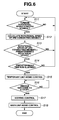
- FIG. 6 is a flowchart depicting a control for preventing over-revolution of the automatic transmission according to the first embodiment of the present invention.
- description will be made as to the case where there is caused such high-speed rotation of the third connecting member M3 that will never occur if the frictional elements are functioning properly but the following control can also be applied to the case where there is caused over-revolution of another connecting member that will never occur if the frictional members are functioning properly.
- step S11 it is determined whether the first turbine speed sensor 3 and the second turbine speed sensor 4 are normal. If the first turbine speed sensor 3 and the second turbine speed sensor 4 are both normal, the control proceeds to the step S12. On the other hand, if either one of the first turbine speed sensor 3 and the second turbine speed sensor 4 is not normal, the step S11 is executed again.
- the abnormality of each of the sensors 3 and 4 is determined based on, for example, whether the detected rotational speed of each of the sensors 3 and 4 at each gear position when the engine is idling is lower than a predetermined value, and when the detected rotational speed is lower than the predetermined value, each of the sensors 3 and 4 is determined abnormal.
- step S12 rotational speed detecting section or means
- the rotational speed of the third connecting member M3 predetermined rotational element
- the rotational speed of the third connecting member M3 is calculated by the following expression (3) on the basis of the rotational speed of the fist carrier PC1 that is the detection value of the first turbine speed sensor 3 and the rotational speed of the first ring gear R1 that is the detection value of the second turbine speed sensor 3.
- N M ⁇ 3 1 + ⁇ 1 / ⁇ 1 ⁇ N PC ⁇ 1 - ( 1 / ⁇ 1 ) N R ⁇ 1
- N M3 is the rotational speed of the third connecting member M3
- N PC1 is the rotational speed of the first carrier PC1
- N R1 is the rotational speed of the first ring gear R1
- ⁇ 1 is the tooth ratio of the planetary gear G1.
- the tooth ratio ⁇ 1 is the ratio between the number Z S1 of teeth of the first sun gear S1 and the number Z R1 of teeth of the first ring gear R1 as shown in the above-described expression (2).
- step S13 it is determined whether the rotational speed of the third connecting member M3 is higher than a predetermined speed. If the rotational speed of the third connecting member M3 is higher than the predetermined speed, the control proceeds to step S14, and if lower, the control goes back to step S11.
- the predetermined rotational speed is higher than a maximum possible value that the third connecting member M3 can attain when the gear position instructed by the ATCU 20 coincides with the gear position corresponding to the gear ratio that is actually realized, i.e., when a normal shift control is performed and is set at, for example, 8000 rpm in consideration of the durability of the third connecting member M3.
- step S14 it is determined whether a predetermined time has elapsed after it was determined in step S13 that the rotational speed of the third connecting member M3 was higher than the predetermined speed. If the predetermined time has elapsed, the control proceeds to step S15, and if not, the control goes back to step S11.
- step S15 (frictional element release section or means), though there is at this time a possibility of a plurality of frictional elements being engaged, a temporary limp-home control is executed to release all of the frictional elements. By this, the transmission is completely put into a neutral state.
- step S16 it is determined whether the vehicle has come to a stop. If the vehicle has come to a stop, the control proceeds to step S17, and if not, the step S16 is executed again. In the meantime, whether the vehicle has come to a stop is determined based on whether the vehicle speed is lower than a predetermined speed (e.g., 5 Km/h).
- a predetermined speed e.g., 5 Km/h
- step S17 a seeking control is executed.
- the seeking control is executed so as to change the instructed gear position from the first to third speed sequentially and specify a malfunctioning frictional element and its malfunctioning state on the basis of the relation between the instructed gear position and the actual gear position that is estimated from the actual gear ratio at each of the instructed gear positions.
- a malfunctioning state a release malfunction in which the frictional element that is instructed to be engaged is not engaged completely but held released and an engagement malfunction in which the frictional element that is instructed to be released is not released but held engaged.
- step S18 a main limp-home control is executed.
- the main limp-home control executes a shift control for selecting, based on the malfunctioning frictional element and its malfunctioning state that are specified in step 17, a gear position that uses the malfunctioning frictional element when the frictional element is suffering the engagement malfunction and a gear position that does not use the malfunctioning frictional element when the frictional element is suffering the release malfunction.
- the predetermined rotational speed is set higher than a maximum possible speed that the third connecting member M3 can attain at the normal time when the gear position instructed by the ATCU 20 and the gear position corresponding to the gear ratio that is actually attained coincide with each other, it becomes possible to prevent such a surplus control that all of the frictional elements are released though the transmission is not malfunctioning.
- the rotational speed of the third connecting member M3 is calculated based on the detection values of the first turbine speed sensor 3 and the second turbine speed sensor 4 that are used for calculating the rotational speed of the input shaft INPUT and a tooth ratio, the rotational speed of the third connecting member M3 that cannot be judged accurately from the rotational speeds of the input shaft INPUT and the output shaft OUTPUT can be estimated accurately. Further, since it is not necessary to provide the transmission with a new sensor for detecting the rotational speed of the third connecting member M3, increase in the cost due to increase in the parts and increase in the weight can be avoided.
- the second embodiment differs from the first embodiment in that a third turbine speed sensor is newly provided. As shown in FIG. 7 , the third turbine speed sensor 3A is disposed adjacent the third connecting member M3 and detects the rotational speed of the third connecting member M3 directly.
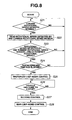
- FIG. 8 shows a flowchart of a control for preventing over-revolution of the automatic transmission according to the second embodiment.
- Step S21 is the same as step S11 of the first embodiment.
- step S22 rotational speed detecting section or means
- the rotational speed of the third connecting member M3 that is detected by the third turbine speed sensor 3A is read.
- the rotational speed of the third connecting member 3A is detected directly so that its estimation is not necessitated.
- step S23 it is determined whether the rotational speed of the third connecting member M3 that is detected by the third turbine speed sensor 3A is higher than a predetermined speed. If the rotational speed of the third connecting member M3 is higher than the predetermined speed, the control proceeds to step S24, and if equal to or lower than the predetermined speed, the control goes back to step S21.
- Steps S24 to S28 are the same as steps S14 to S18 of the first embodiment.
- the rotational speed of the third connecting member M3 is directly detected by the third turbine speed sensor 3A so that it is not necessary to estimate the rotational speed of the third connecting member M3 and occurrence of over-revolution can be prevented more assuredly depending upon the accurate detection value.
Landscapes
- Engineering & Computer Science (AREA)
- General Engineering & Computer Science (AREA)
- Mechanical Engineering (AREA)
- Control Of Transmission Device (AREA)
- Structure Of Transmissions (AREA)
Applications Claiming Priority (1)
| Application Number | Priority Date | Filing Date | Title |
|---|---|---|---|
| JP2007065207A JP4358248B2 (ja) | 2007-03-14 | 2007-03-14 | 自動変速機 |
Publications (3)
| Publication Number | Publication Date |
|---|---|
| EP1970600A2 true EP1970600A2 (de) | 2008-09-17 |
| EP1970600A3 EP1970600A3 (de) | 2011-01-19 |
| EP1970600B1 EP1970600B1 (de) | 2012-04-11 |
Family
ID=39310010
Family Applications (1)
| Application Number | Title | Priority Date | Filing Date |
|---|---|---|---|
| EP08002971A Ceased EP1970600B1 (de) | 2007-03-14 | 2008-02-18 | Automatikgetriebe und Verfahren zur Verhinderung von dessen Überdrehung |
Country Status (5)
| Country | Link |
|---|---|
| US (1) | US7901315B2 (de) |
| EP (1) | EP1970600B1 (de) |
| JP (1) | JP4358248B2 (de) |
| KR (1) | KR101455862B1 (de) |
| CN (1) | CN101265972B (de) |
Cited By (1)
| Publication number | Priority date | Publication date | Assignee | Title |
|---|---|---|---|---|
| CN101492051B (zh) * | 2009-01-07 | 2011-07-27 | 潍柴动力股份有限公司 | 用于控制车辆的方法和系统 |
Families Citing this family (2)
| Publication number | Priority date | Publication date | Assignee | Title |
|---|---|---|---|---|
| JP4920064B2 (ja) * | 2009-09-02 | 2012-04-18 | ジヤトコ株式会社 | 自動変速機の制御装置 |
| JP4951658B2 (ja) * | 2009-09-02 | 2012-06-13 | ジヤトコ株式会社 | 自動変速機の制御装置 |
Citations (2)
| Publication number | Priority date | Publication date | Assignee | Title |
|---|---|---|---|---|
| JPH0989098A (ja) | 1995-09-20 | 1997-03-31 | Mitsubishi Motors Corp | 自動変速機の変速制御装置 |
| JP2007065207A (ja) | 2005-08-30 | 2007-03-15 | Fujifilm Corp | 光学補償シート、並びにそれを用いた偏光板及び液晶表示装置 |
Family Cites Families (45)
| Publication number | Priority date | Publication date | Assignee | Title |
|---|---|---|---|---|
| JPS62151656A (ja) * | 1985-12-24 | 1987-07-06 | Toyota Motor Corp | 車両用自動変速機のフエイルセ−フ装置 |
| US4843551A (en) * | 1987-09-28 | 1989-06-27 | Saturn Corporation | Failure mode shift pattern alteration for an electronically controlled transmission |
| JPH01172660A (ja) | 1987-12-28 | 1989-07-07 | Aisin Aw Co Ltd | 電子制御式自動変速機のフェールセーフ制御装置 |
| JPH0242268A (ja) * | 1988-08-01 | 1990-02-13 | Nissan Motor Co Ltd | パワートレーンの総合制御装置 |
| JPH02304262A (ja) | 1989-05-19 | 1990-12-18 | Nissan Motor Co Ltd | 自動変速機のライン圧制御装置 |
| JPH03113161A (ja) | 1989-09-22 | 1991-05-14 | Toyota Motor Corp | 自動変速機のコースト制御装置 |
| US5113725A (en) * | 1989-09-22 | 1992-05-19 | Toyota Jidosha Kabushiki Kaisha | Hydraulic control device of automatic transmission more smooth in low coast upshifting under under-D manual shift range |
| JP2811910B2 (ja) | 1990-05-08 | 1998-10-15 | トヨタ自動車株式会社 | 車両用自動変速機の制御装置 |
| US5233890A (en) * | 1992-03-31 | 1993-08-10 | Saturn Corporation | Transmission torque converter clutch disable control |
| JPH05288264A (ja) | 1992-04-10 | 1993-11-02 | Mazda Motor Corp | 多段自動変速装置 |
| US5439427A (en) * | 1992-04-10 | 1995-08-08 | Mazda Motor Corporation | Multiple stage automatic transmission |
| JPH05346160A (ja) | 1992-06-12 | 1993-12-27 | Mazda Motor Corp | 自動変速機の制御装置 |
| JPH06109129A (ja) | 1992-09-24 | 1994-04-19 | Mitsubishi Electric Corp | 自動変速機の制御装置 |
| GB2278654B (en) * | 1993-06-03 | 1997-11-19 | Toyota Motor Co Ltd | Shift control system for automatic transmission |
| JP3173330B2 (ja) * | 1994-07-20 | 2001-06-04 | トヨタ自動車株式会社 | 車両用ロックアップクラッチのスリップ制御装置 |
| JP3523351B2 (ja) * | 1994-12-27 | 2004-04-26 | ジヤトコ株式会社 | 自動変速機の制御方法およびその装置 |
| JPH08219274A (ja) | 1995-02-08 | 1996-08-27 | Nissan Motor Co Ltd | 自動変速機の故障診断装置 |
| JP3528434B2 (ja) | 1996-05-29 | 2004-05-17 | トヨタ自動車株式会社 | 自動変速機の制御装置 |
| JPH11108173A (ja) * | 1997-09-30 | 1999-04-20 | Mazda Motor Corp | 自動変速機の制御装置 |
| JP4094100B2 (ja) * | 1997-12-25 | 2008-06-04 | 富士重工業株式会社 | 自動変速機の油圧制御装置 |
| JP3858439B2 (ja) | 1998-03-30 | 2006-12-13 | マツダ株式会社 | 自動変速機の制御装置 |
| JPH11280896A (ja) | 1998-03-30 | 1999-10-15 | Mazda Motor Corp | 自動変速機の故障検出装置 |
| JP2000240785A (ja) | 1999-02-18 | 2000-09-05 | Fuji Heavy Ind Ltd | 自動変速機のフェールセーフ方法 |
| JP3691691B2 (ja) | 1999-08-06 | 2005-09-07 | ジヤトコ株式会社 | 自動変速機の故障検出装置 |
| JP3736604B2 (ja) * | 1999-08-20 | 2006-01-18 | ジヤトコ株式会社 | 自動変速機の故障時変速制御装置 |
| US6319164B1 (en) * | 2000-05-23 | 2001-11-20 | General Motors Corporation | Electro-hydraulic control with a manual selection valve |
| US6520881B1 (en) * | 2001-08-06 | 2003-02-18 | General Motors Corporation | Fly-by-wire electro-hydraulic control mechanism for a six speed transmission |
| JP2003097691A (ja) | 2001-09-27 | 2003-04-03 | Jatco Ltd | 自動変速機の変速制御装置 |
| JP3688250B2 (ja) * | 2002-04-17 | 2005-08-24 | トヨタ自動車株式会社 | 自動変速機の制御装置および制御方法 |
| JP2004068989A (ja) | 2002-08-08 | 2004-03-04 | Toyota Motor Corp | 車両用自動変速機の故障検出装置 |
| JP3938535B2 (ja) * | 2002-09-30 | 2007-06-27 | 日産ディーゼル工業株式会社 | 自動変速機の制御装置 |
| JP4214405B2 (ja) * | 2004-08-19 | 2009-01-28 | 株式会社デンソー | 自動変速機の制御装置 |
| US7140993B2 (en) * | 2004-10-28 | 2006-11-28 | General Motors Corporation | Fly-by-wire limp home and multi-plex system |
| DE502005006690D1 (de) * | 2005-04-07 | 2009-04-09 | Getrag Ford Transmissions Gmbh | Schaltventilvorrichtung für ein Schaltsystem eines Schaltgetriebes |
| JP4220494B2 (ja) * | 2005-05-31 | 2009-02-04 | ジヤトコ株式会社 | 自動変速機の故障時制御装置 |
| JP4353148B2 (ja) * | 2005-07-13 | 2009-10-28 | トヨタ自動車株式会社 | 自動変速機の制御装置 |
| JP4388915B2 (ja) * | 2005-07-14 | 2009-12-24 | ジヤトコ株式会社 | 自動変速機の制御装置 |
| JP4158792B2 (ja) * | 2005-07-22 | 2008-10-01 | トヨタ自動車株式会社 | 車両用自動変速機の油圧制御装置 |
| JP4220536B2 (ja) * | 2006-06-22 | 2009-02-04 | ジヤトコ株式会社 | 自動変速機の制御装置 |
| JP2008069829A (ja) * | 2006-09-13 | 2008-03-27 | Jatco Ltd | 自動変速機の異常判定装置 |
| JP4609418B2 (ja) * | 2006-11-15 | 2011-01-12 | トヨタ自動車株式会社 | シフト切換機構の制御装置および制御方法 |
| JP4263210B2 (ja) * | 2006-12-20 | 2009-05-13 | ジヤトコ株式会社 | 自動変速機 |
| JP4404911B2 (ja) * | 2007-01-09 | 2010-01-27 | ジヤトコ株式会社 | 自動変速機 |
| US7648440B2 (en) * | 2007-01-24 | 2010-01-19 | Gm Global Technology Operations, Inc. | Method and apparatus to control operation of an electro-mechanical transmission |
| KR101469279B1 (ko) * | 2007-03-09 | 2014-12-04 | 쟈트코 가부시키가이샤 | 자동 변속기 |
-
2007
- 2007-03-14 JP JP2007065207A patent/JP4358248B2/ja active Active
-
2008
- 2008-02-12 US US12/029,632 patent/US7901315B2/en active Active
- 2008-02-18 EP EP08002971A patent/EP1970600B1/de not_active Ceased
- 2008-02-29 KR KR1020080018848A patent/KR101455862B1/ko not_active Expired - Fee Related
- 2008-03-14 CN CN2008100853367A patent/CN101265972B/zh active Active
Patent Citations (2)
| Publication number | Priority date | Publication date | Assignee | Title |
|---|---|---|---|---|
| JPH0989098A (ja) | 1995-09-20 | 1997-03-31 | Mitsubishi Motors Corp | 自動変速機の変速制御装置 |
| JP2007065207A (ja) | 2005-08-30 | 2007-03-15 | Fujifilm Corp | 光学補償シート、並びにそれを用いた偏光板及び液晶表示装置 |
Cited By (1)
| Publication number | Priority date | Publication date | Assignee | Title |
|---|---|---|---|---|
| CN101492051B (zh) * | 2009-01-07 | 2011-07-27 | 潍柴动力股份有限公司 | 用于控制车辆的方法和系统 |
Also Published As
| Publication number | Publication date |
|---|---|
| KR101455862B1 (ko) | 2014-11-03 |
| JP4358248B2 (ja) | 2009-11-04 |
| EP1970600B1 (de) | 2012-04-11 |
| KR20080084598A (ko) | 2008-09-19 |
| US20080227580A1 (en) | 2008-09-18 |
| US7901315B2 (en) | 2011-03-08 |
| CN101265972B (zh) | 2012-09-26 |
| JP2008223941A (ja) | 2008-09-25 |
| CN101265972A (zh) | 2008-09-17 |
| EP1970600A3 (de) | 2011-01-19 |
Similar Documents
| Publication | Publication Date | Title |
|---|---|---|
| JP4418477B2 (ja) | 自動変速機 | |
| EP1936241B1 (de) | Automatikgetriebe | |
| JP4910026B2 (ja) | 自動変速機の制御装置及びその学習方法 | |
| EP1898129A2 (de) | Steuervorrichtung für ein Automatikgetriebe mit Ausfallsicherungsfunktion bei einem stehendem Fahrzeug | |
| EP1770314B1 (de) | Automatikgetriebe | |
| KR101469279B1 (ko) | 자동 변속기 | |
| JP2007263336A (ja) | 自動変速装置の制御装置 | |
| JP4431590B2 (ja) | 自動変速機 | |
| EP1970600B1 (de) | Automatikgetriebe und Verfahren zur Verhinderung von dessen Überdrehung | |
| JP6212637B2 (ja) | 車両の制御装置 | |
| JP5027204B2 (ja) | 自動変速機 | |
| JP4350694B2 (ja) | 自動変速装置の制御装置 | |
| JP5080545B2 (ja) | 自動変速機 | |
| JP4499053B2 (ja) | 自動変速装置の制御装置 | |
| JP4398967B2 (ja) | 自動変速装置の制御装置 | |
| JP4965700B2 (ja) | 自動変速装置の制御装置 | |
| JP4663566B2 (ja) | 自動変速装置の制御装置 | |
| JP4436381B2 (ja) | 自動変速機 |
Legal Events
| Date | Code | Title | Description |
|---|---|---|---|
| PUAI | Public reference made under article 153(3) epc to a published international application that has entered the european phase |
Free format text: ORIGINAL CODE: 0009012 |
|
| AK | Designated contracting states |
Kind code of ref document: A2 Designated state(s): AT BE BG CH CY CZ DE DK EE ES FI FR GB GR HR HU IE IS IT LI LT LU LV MC MT NL NO PL PT RO SE SI SK TR |
|
| AX | Request for extension of the european patent |
Extension state: AL BA MK RS |
|
| PUAL | Search report despatched |
Free format text: ORIGINAL CODE: 0009013 |
|
| AK | Designated contracting states |
Kind code of ref document: A3 Designated state(s): AT BE BG CH CY CZ DE DK EE ES FI FR GB GR HR HU IE IS IT LI LT LU LV MC MT NL NO PL PT RO SE SI SK TR |
|
| AX | Request for extension of the european patent |
Extension state: AL BA MK RS |
|
| 17P | Request for examination filed |
Effective date: 20110714 |
|
| GRAP | Despatch of communication of intention to grant a patent |
Free format text: ORIGINAL CODE: EPIDOSNIGR1 |
|
| AKX | Designation fees paid |
Designated state(s): DE FR IT |
|
| RIN1 | Information on inventor provided before grant (corrected) |
Inventor name: SHINSO, YOSHIHIDEC/O JATCO LTD. Inventor name: KAWAGUCHI, TAKATERUC/O JATCO LTD. Inventor name: NAGASHIMA, FUMITAKAC/O JATCO LTD. Inventor name: MOCHIYAMA, SHINYAC/O JATCO LTD. |
|
| GRAS | Grant fee paid |
Free format text: ORIGINAL CODE: EPIDOSNIGR3 |
|
| GRAA | (expected) grant |
Free format text: ORIGINAL CODE: 0009210 |
|
| AK | Designated contracting states |
Kind code of ref document: B1 Designated state(s): DE FR IT |
|
| REG | Reference to a national code |
Ref country code: DE Ref legal event code: R096 Ref document number: 602008014706 Country of ref document: DE Effective date: 20120614 |
|
| PLBE | No opposition filed within time limit |
Free format text: ORIGINAL CODE: 0009261 |
|
| STAA | Information on the status of an ep patent application or granted ep patent |
Free format text: STATUS: NO OPPOSITION FILED WITHIN TIME LIMIT |
|
| PG25 | Lapsed in a contracting state [announced via postgrant information from national office to epo] |
Ref country code: IT Free format text: LAPSE BECAUSE OF FAILURE TO SUBMIT A TRANSLATION OF THE DESCRIPTION OR TO PAY THE FEE WITHIN THE PRESCRIBED TIME-LIMIT Effective date: 20120411 |
|
| 26N | No opposition filed |
Effective date: 20130114 |
|
| REG | Reference to a national code |
Ref country code: DE Ref legal event code: R097 Ref document number: 602008014706 Country of ref document: DE Effective date: 20130114 |
|
| REG | Reference to a national code |
Ref country code: DE Ref legal event code: R082 Ref document number: 602008014706 Country of ref document: DE Representative=s name: GRUENECKER, KINKELDEY, STOCKMAIR & SCHWANHAEUS, DE |
|
| REG | Reference to a national code |
Ref country code: DE Ref legal event code: R081 Ref document number: 602008014706 Country of ref document: DE Owner name: NISSAN MOTOR CO., LTD., YOKOHAMA-SHI, JP Free format text: FORMER OWNER: JATCO LTD., FUJI-SHI, SHIZUOKA, JP Effective date: 20140124 Ref country code: DE Ref legal event code: R081 Ref document number: 602008014706 Country of ref document: DE Owner name: JATCO LTD, FUJI, JP Free format text: FORMER OWNER: JATCO LTD., FUJI-SHI, SHIZUOKA, JP Effective date: 20140124 Ref country code: DE Ref legal event code: R082 Ref document number: 602008014706 Country of ref document: DE Representative=s name: GRUENECKER PATENT- UND RECHTSANWAELTE PARTG MB, DE Effective date: 20140124 Ref country code: DE Ref legal event code: R082 Ref document number: 602008014706 Country of ref document: DE Representative=s name: GRUENECKER, KINKELDEY, STOCKMAIR & SCHWANHAEUS, DE Effective date: 20140124 Ref country code: DE Ref legal event code: R081 Ref document number: 602008014706 Country of ref document: DE Owner name: NISSAN MOTOR CO., LTD., JP Free format text: FORMER OWNER: JATCO LTD., FUJI-SHI, JP Effective date: 20140124 Ref country code: DE Ref legal event code: R081 Ref document number: 602008014706 Country of ref document: DE Owner name: JATCO LTD, JP Free format text: FORMER OWNER: JATCO LTD., FUJI-SHI, JP Effective date: 20140124 |
|
| REG | Reference to a national code |
Ref country code: FR Ref legal event code: TQ Owner name: NISSAN MOTOR CO., LTD, JP Effective date: 20140217 Ref country code: FR Ref legal event code: TQ Owner name: JATCO LTD, JP Effective date: 20140217 |
|
| REG | Reference to a national code |
Ref country code: FR Ref legal event code: PLFP Year of fee payment: 9 |
|
| REG | Reference to a national code |
Ref country code: FR Ref legal event code: PLFP Year of fee payment: 10 |
|
| REG | Reference to a national code |
Ref country code: FR Ref legal event code: PLFP Year of fee payment: 11 |
|
| PGFP | Annual fee paid to national office [announced via postgrant information from national office to epo] |
Ref country code: DE Payment date: 20180206 Year of fee payment: 11 |
|
| PGFP | Annual fee paid to national office [announced via postgrant information from national office to epo] |
Ref country code: FR Payment date: 20180111 Year of fee payment: 11 |
|
| REG | Reference to a national code |
Ref country code: DE Ref legal event code: R119 Ref document number: 602008014706 Country of ref document: DE |
|
| PG25 | Lapsed in a contracting state [announced via postgrant information from national office to epo] |
Ref country code: DE Free format text: LAPSE BECAUSE OF NON-PAYMENT OF DUE FEES Effective date: 20190903 |
|
| PG25 | Lapsed in a contracting state [announced via postgrant information from national office to epo] |
Ref country code: FR Free format text: LAPSE BECAUSE OF NON-PAYMENT OF DUE FEES Effective date: 20190228 |