EP1957325B1 - Systeme de retenue d'un passager de vehicule, dote d'un sac a gaz gonflable et monte dans un siege de vehicule - Google Patents
Systeme de retenue d'un passager de vehicule, dote d'un sac a gaz gonflable et monte dans un siege de vehicule Download PDFInfo
- Publication number
- EP1957325B1 EP1957325B1 EP06829336A EP06829336A EP1957325B1 EP 1957325 B1 EP1957325 B1 EP 1957325B1 EP 06829336 A EP06829336 A EP 06829336A EP 06829336 A EP06829336 A EP 06829336A EP 1957325 B1 EP1957325 B1 EP 1957325B1
- Authority
- EP
- European Patent Office
- Prior art keywords
- airbag
- restraint system
- backrest frame
- vehicle occupant
- occupant restraint
- Prior art date
- Legal status (The legal status is an assumption and is not a legal conclusion. Google has not performed a legal analysis and makes no representation as to the accuracy of the status listed.)
- Not-in-force
Links
- 230000006641 stabilisation Effects 0.000 claims description 4
- 238000011105 stabilization Methods 0.000 claims description 4
- 230000001960 triggered effect Effects 0.000 abstract description 2
- 239000004744 fabric Substances 0.000 description 53
- 208000027418 Wounds and injury Diseases 0.000 description 2
- 230000006378 damage Effects 0.000 description 2
- 208000014674 injury Diseases 0.000 description 2
- 239000002184 metal Substances 0.000 description 2
- 238000009958 sewing Methods 0.000 description 2
- 241001474791 Proboscis Species 0.000 description 1
- 238000010521 absorption reaction Methods 0.000 description 1
- 210000000078 claw Anatomy 0.000 description 1
- 238000010276 construction Methods 0.000 description 1
- 239000012530 fluid Substances 0.000 description 1
- 230000003116 impacting effect Effects 0.000 description 1
- 238000012986 modification Methods 0.000 description 1
- 230000004048 modification Effects 0.000 description 1
- 238000004806 packaging method and process Methods 0.000 description 1
- 230000035939 shock Effects 0.000 description 1
- 230000000087 stabilizing effect Effects 0.000 description 1
Images


Classifications
-
- B—PERFORMING OPERATIONS; TRANSPORTING
- B60—VEHICLES IN GENERAL
- B60R—VEHICLES, VEHICLE FITTINGS, OR VEHICLE PARTS, NOT OTHERWISE PROVIDED FOR
- B60R21/00—Arrangements or fittings on vehicles for protecting or preventing injuries to occupants or pedestrians in case of accidents or other traffic risks
- B60R21/02—Occupant safety arrangements or fittings, e.g. crash pads
- B60R21/16—Inflatable occupant restraints or confinements designed to inflate upon impact or impending impact, e.g. air bags
- B60R21/23—Inflatable members
- B60R21/231—Inflatable members characterised by their shape, construction or spatial configuration
- B60R21/233—Inflatable members characterised by their shape, construction or spatial configuration comprising a plurality of individual compartments; comprising two or more bag-like members, one within the other
-
- B—PERFORMING OPERATIONS; TRANSPORTING
- B60—VEHICLES IN GENERAL
- B60R—VEHICLES, VEHICLE FITTINGS, OR VEHICLE PARTS, NOT OTHERWISE PROVIDED FOR
- B60R21/00—Arrangements or fittings on vehicles for protecting or preventing injuries to occupants or pedestrians in case of accidents or other traffic risks
- B60R21/02—Occupant safety arrangements or fittings, e.g. crash pads
- B60R21/16—Inflatable occupant restraints or confinements designed to inflate upon impact or impending impact, e.g. air bags
- B60R21/20—Arrangements for storing inflatable members in their non-use or deflated condition; Arrangement or mounting of air bag modules or components
- B60R21/207—Arrangements for storing inflatable members in their non-use or deflated condition; Arrangement or mounting of air bag modules or components in vehicle seats
-
- B—PERFORMING OPERATIONS; TRANSPORTING
- B60—VEHICLES IN GENERAL
- B60R—VEHICLES, VEHICLE FITTINGS, OR VEHICLE PARTS, NOT OTHERWISE PROVIDED FOR
- B60R21/00—Arrangements or fittings on vehicles for protecting or preventing injuries to occupants or pedestrians in case of accidents or other traffic risks
- B60R21/02—Occupant safety arrangements or fittings, e.g. crash pads
- B60R21/16—Inflatable occupant restraints or confinements designed to inflate upon impact or impending impact, e.g. air bags
- B60R21/23—Inflatable members
- B60R21/231—Inflatable members characterised by their shape, construction or spatial configuration
- B60R21/2334—Expansion control features
- B60R21/2338—Tethers
-
- B—PERFORMING OPERATIONS; TRANSPORTING
- B60—VEHICLES IN GENERAL
- B60R—VEHICLES, VEHICLE FITTINGS, OR VEHICLE PARTS, NOT OTHERWISE PROVIDED FOR
- B60R21/00—Arrangements or fittings on vehicles for protecting or preventing injuries to occupants or pedestrians in case of accidents or other traffic risks
- B60R21/02—Occupant safety arrangements or fittings, e.g. crash pads
- B60R21/16—Inflatable occupant restraints or confinements designed to inflate upon impact or impending impact, e.g. air bags
- B60R21/23—Inflatable members
- B60R21/231—Inflatable members characterised by their shape, construction or spatial configuration
- B60R21/233—Inflatable members characterised by their shape, construction or spatial configuration comprising a plurality of individual compartments; comprising two or more bag-like members, one within the other
- B60R2021/23324—Inner walls crating separate compartments, e.g. communicating with vents
-
- B—PERFORMING OPERATIONS; TRANSPORTING
- B60—VEHICLES IN GENERAL
- B60R—VEHICLES, VEHICLE FITTINGS, OR VEHICLE PARTS, NOT OTHERWISE PROVIDED FOR
- B60R21/00—Arrangements or fittings on vehicles for protecting or preventing injuries to occupants or pedestrians in case of accidents or other traffic risks
- B60R21/02—Occupant safety arrangements or fittings, e.g. crash pads
- B60R21/16—Inflatable occupant restraints or confinements designed to inflate upon impact or impending impact, e.g. air bags
- B60R21/23—Inflatable members
- B60R21/231—Inflatable members characterised by their shape, construction or spatial configuration
- B60R21/2334—Expansion control features
- B60R21/2338—Tethers
- B60R2021/23382—Internal tether means
-
- B—PERFORMING OPERATIONS; TRANSPORTING
- B60—VEHICLES IN GENERAL
- B60R—VEHICLES, VEHICLE FITTINGS, OR VEHICLE PARTS, NOT OTHERWISE PROVIDED FOR
- B60R21/00—Arrangements or fittings on vehicles for protecting or preventing injuries to occupants or pedestrians in case of accidents or other traffic risks
- B60R21/02—Occupant safety arrangements or fittings, e.g. crash pads
- B60R21/16—Inflatable occupant restraints or confinements designed to inflate upon impact or impending impact, e.g. air bags
- B60R21/23—Inflatable members
- B60R21/231—Inflatable members characterised by their shape, construction or spatial configuration
- B60R21/23138—Inflatable members characterised by their shape, construction or spatial configuration specially adapted for side protection
Definitions
- the invention relates to a vehicle occupant restraint system having an inflatable airbag arranged in a vehicle seat according to the preamble of patent claim 1.
- an airbag arrangement in which an airbag of the vehicle door facing away from the side of a vehicle seat is mounted in the vehicle seat. When triggered, the airbag unfolds in the direction of travel, which is to be achieved so that a vehicle occupant can not be thrown laterally out of the vehicle seat.
- the airbag used in this case is stabilized and positioned by means of a band arranged on the outside of the airbag.
- the invention is characterized by connecting a gas bag of the vehicle occupant restraint system at the front end in the direction of travel of the back frame with this.
- the connection of the gas bag with the back frame is carried out by means of an additional fabric layer, which is connected to the one with the gas bag and the other with the front end of the back frame.
- the formed connection of the gas bag with the back frame takes place along a connecting line which extends according to the shape of the back frame substantially in the vertical direction.
- a back frame extends on both sides of a vehicle seat, wherein the back frame is oriented substantially in the direction of travel and accordingly has a front, pointing in the direction of travel and a rear, facing away from the direction of travel end.
- the front end of the backrest frame comprises on the one hand facing in the direction of travel front side of the backrest frame.
- the front end of the backrest frame also includes areas of the backrest frame, which adjoin the front side.
- a front end in the sense of the present invention is present as long as the distance between the Connection structure for attaching the airbag to the back frame and the front of the back frame is not greater than half the distance between the front and the rear end of the back frame in the direction of travel.
- connection structure is thus arranged in the front half of the backrest frame.
- the distance between the connection structure for fastening the airbag to the backrest frame and the front side of the backrest frame is not more than a quarter of the distance between the front side and the rear end of the backrest frame in the direction of travel.
- the solution according to the invention can largely restrict sideways movement or oblique forward movement of an occupant in the event of a side impact.
- the solution provided can easily interact with conventional three-point belt systems.
- a kink-resistant as possible gas bag which restricts a sideways movement or oblique forward movement of a vehicle occupant in a side impact safely.
- the function of the gas bag the restraint of a vehicle occupant.
- the function of energy absorption by the gas bag is of only secondary importance. Accordingly, it is preferably provided to realize a high pressure of about 2 bar in the gas bag and to make it gas-tight, i. without air outlets form.
- connection of the gas bag with the back frame along a connecting line, which extends in accordance with the shape of the back frame substantially in the vertical direction.
- the gas bag is connected along the connecting line, for example by means of a plurality of fastening points (eg screw) with the back frame.
- connection of the gas bag to the back frame is effected by means of an additional fabric layer, which is connected on the one hand to the gas bag and on the other hand to the front end of the back frame.
- the connection of the additional fabric layer with the gas bag is effected, for example, by sewing the additional fabric layer and with one of the fabric layers of the gas bag, the sewing taking place at least along the circumference of the additional fabric layer.
- the additional fabric layer is glued to one of the fabric layers of the gas bag, either along its edge region or over its entire surface.
- the additional fabric layer is guided, for example, around a holding part connected to the front end of the backrest frame, which is screwed to the end face of the backrest frame for example.
- a connection of the airbag to the front end of the backrest frame is achieved in a simple manner over a defined vertical length.
- the additional fabric layer forms a loop.
- the vehicle occupant restraint system preferably has an airbag module carrier for fastening a gas generator as well as the airbag packaging with the folded airbag thereto.
- the module carrier is formed, for example, as a bent sheet metal part. It is preferably provided that such a module carrier is connected to the front end of the back frame. In this case, the module carrier can be connected to the back frame together with a holding part, which serves to attach the additional fabric layer to the back frame. This provides a simple construction. In another embodiment, the module carrier fully or partially inserted into a loop or pocket which forms the additional fabric layer.
- the gas bag has one or more darts for forming one or more non-inflatable portions of the gas bag.
- the darts are preferably designed such that the gas bag forms at least one buckling-resistant, substantially vertical column and / or at least one buckling-resistant, substantially horizontally extending column.
- Such a pillar or a plurality of such pillars are stabilized and positioned by the subregion of the airbag which is directly adjacent to the backrest frame.
- the partial region of the inflated gas bag which is connected to the additional fabric layer, is supported on the backrest frame, thereby providing stabilization and positioning of the gas bag as a whole.
- the FIG. 1 shows a vehicle occupant restraint system for protecting a shock-resistant vehicle occupant 20 in a side impact.
- the restraint system comprises an airbag 3, which is attached to the backrest frame 11 of a vehicle seat 10.
- a vehicle seat 10 has generally in the region of its backrest on the two sides of the backrest in each case a backrest frame, of which a back frame 11 in the FIG. 1 is shown.
- a backrest frame On the other side of the vehicle seat 11 is a corresponding back frame, which, however, usually has no or a trained otherwise gas bag, which is why only one back frame 11 is shown.
- the vehicle occupant restraint system can also be realized in the case of a driver's seat or a seat arranged centrally or left in the rear (the airbag then being arranged on the right-hand side of the seat).
- the preferred implementation is thus a so-called mid-mount side airbag.
- the vehicle occupant 20 In a side impact, the vehicle occupant 20, whose torso 21 and head 22 are shown, experiences a force acting in the direction of the arrow F, which is suitable for ejecting the vehicle occupant from the vehicle seat 10.
- the gas bag 3 attached to the back frame 11 is provided.
- the shock-facing vehicle occupant 21 does not move out of the region of his seat during the side impact and thus a risk of injury by contact with Vehicle elements or other vehicle occupants prevented or reduced.
- the gas bag 3 is formed as stable as possible and kink-resistant.
- the airbag 3 is according to the FIG. 2 via the additional fabric layer 31, which is connected to a fabric layer 39 of the gas bag 3, directly connected to the facing in the direction of travel end face 12 of the back frame 12.
- a kind of pocket 310 of the additional fabric layer 31, a holding part 70 and screws 60 are provided, which cooperate as follows.
- the additional fabric layer 31 is guided in the region of the pocket 310 around the flat part and extending along the end face 12 of the back frame holding part 70.
- screws 60 By means of screws 60, the fabric pocket 310 and the holding part 70 are screwed to the end face 12 of the back frame 11.
- the additional fabric layer 31 and thus the gas bag 3 via a defined Length connected to the backrest frame 11 extending in the vertical direction, and namely at its front side pointing in the direction of travel 12th
- a module carrier 40 is connected to the backrest frame 11 via the screw connection 60, to which the module carrier 40, which is preferably formed from sheet metal, forms a flat region 41 which directly adjoins the end face 12 of the backrest frame 11 and which together with the two fabric layers of the fabric bag 310 and the holding part 70 is screwed.
- the module carrier 40 is formed on its end facing away from the end face 12 of the back frame 11 for receiving and mounting a gas generator 50, which is shown schematically.
- Such other components are e.g. a module housing, airbag sensors and a control device.
- Such further elements are not shown separately in the figures, since they are well known to the skilled person.
- FIG. 3 shows the vehicle occupant restraint system of FIG. 1 in lateral view.
- a dashed line 36 indicates the connecting line, along which the additional fabric layer 31 is connected to the one fabric layer 39 of the airbag 3.
- dashed lines, a connecting line 37 is shown, along which the additional fabric part 31 as shown in the FIG. 2 is connected to the front side 12 of the back frame 11.
- the additional fabric layer 31 is connected along its circumference to the corresponding fabric layer 39 of the gas bag 3.
- the additional fabric layer 31 is bonded to the corresponding fabric layer 39 of the airbag, along its circumference or over a large area.
- the gas bag 3 further has two darts 33, 34, which each form a non-inflatable portion 330, 340 of the gas bag.
- the airbag 3 Upon deployment of the airbag 3, this forms in the region which is connected to the additional fabric layer 31, a highly stabilized portion 360, which is directly supported on the back frame 11 and thereby provides a stabilization and positioning of the airbag 3 total.
- the airbag 3 By connecting the airbag 3 at the front end in the direction of travel of the backrest frame 11, the airbag 3 can extend far in the direction of travel of the backrest 10, so that even with an oblique forward motion an accelerated vehicle occupant is restrained.
- the area 360 of the connection of the airbag 3 to the backrest frame 11 additionally represents a subregion which stabilizes and positions directly on the backrest frame 11 due to the additional fabric layer 31 and the support.
- the gas bag 3 forms in the embodiment of FIG. 3 the gas bag 3 in the direction of travel adjacent to the non-inflatable sections 330, 340 (and formed by them) a substantially vertically extending, kink-resistant column 350 from. Furthermore, the gas bag 3 forms a substantially horizontally extending column 370 below the non-inflatable portion 330. These columns 350, 370 are also stabilized via the stabilizing portion 360 and strengthened against buckling or deflection.
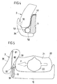
- FIG. 6 shows a modification of the embodiment of FIGS. 1 to 3 ,
- an airbag 3 with two fabric layers 38, 39, a back frame 11, a module carrier 40 ', a gas generator 50, an additional fabric layer 31' and an attachment 60 'for connecting the additional fabric layer 31' provided with the back frame 11 ,
- the additional fabric layer 31 'to the airbag 3 or its fabric layer 39 two seams 36', 36a 'are provided.
- the one seam 36a ' extends adjacent to and thus substantially congruent with the attachment 60' and provided by the attachment 60 ', perpendicular to the image plane extending attachment line between the airbag 3 and the back frame 11.
- the further seam 36 ' connects an edge region of the additional fabric layer 31' to the gas bag.
- the further seam 36 ' can be formed circumferentially, so that even in the rear direction in the direction of travel (adjacent to the module carrier 40') there is a connection between additional fabric layer 31 'and airbag 3.
- additional seams may be present.
- the attachment 60 ' is formed, for example, by means of screws or bolts and, in one embodiment, passes through the layer 312' facing away from the gas bag 3 as well as the module carrier 40 '. Corresponding screws or bolts can be preassembled on the module carrier 40 '. In other embodiments, the attachment 60 'passes through both layers 311', 312 'of the additional tissue mounts 31' and the module carrier 40 '.
- the airbag 3 is in the embodiment of FIG. 4 from two sub-chambers, one extending in the direction of travel main chamber 3a, which is filled in the case of release alone directly with the gas of the gas generator 50 and an associated with the main chamber 3a auxiliary chamber 3b.
- the additional chamber 3b closes on the side facing away from the direction of travel of the main chamber 3a to this.
- the additional chamber 3b is now shaped such that it covers the vehicle seat at its side facing away from the direction of travel, ie the rear side laterally at least partially in the manner of a claw.
- the additional chamber 3b and the encompassing of the seat back of the airbag 3 is additionally stabilized in total, so that the main chamber 3a has a higher buckling resistance and positional stability upon impact of a vehicle occupant.
- the additional chamber 3b is preferably formed sickle-shaped in cross-section or boomerang-shaped, whereby embracing the back of the vehicle seat is particularly effective possible.
- the flow connection 90 between the two chambers 3a, 3n can basically be designed in any desired manner.
- the existing representation is only to be understood schematically.
- a proboscis can project into the other chamber 3b, via which gas is introduced into the additional chamber 3b from a certain internal pressure in the main chamber 3a.
- an additional chamber 3b also a plurality of additional chambers may be provided, either all the additional chambers are filled by the main chamber 3a or another additional chamber is filled by an additional chamber previously filled by the main chamber.
- tether 80 not only a tether 80, but a plurality of tethers are provided, which may be parallel or intersecting formed.
- the gas generator 50 is located behind the gas bag 3 and the tube 51 is bent out of the image plane.
- the gas generator 50 is partially or completely disposed within the airbag 3.
- the outlet opening of the gas generator 50 (not shown) is located inside the airbag 3.
- the one end of the gas generator 50 is in the embodiment of FIG. 8 outside of the gas bag, however, may alternatively also be arranged in the gas bag 3.
- this has a slot 301 in one of its layers.
- the gas bag 3 is attached directly to the gas generator 50, for example by means of a clamping connection.
- the folded airbag fabric lies in one embodiment in the x-direction (ie in the direction of travel) in front of the filling element. This will ensure that the unfolding is directed primarily in the x-direction. Otherwise, there would be the risk that the airbag is deploying too much in the direction of the interior (y-direction).
- FIGS. 1 to 3 , of the FIG. 4 and the FIG. 5 can also be combined.
- the gas bag of FIG. 1 or the FIG. 6 a tether 80 corresponding to FIG. 5 or an additional chamber 3b according to the FIG. 4 form.
Landscapes
- Engineering & Computer Science (AREA)
- Mechanical Engineering (AREA)
- Air Bags (AREA)
Abstract
Claims (26)
- Système de retenue d'un passager de véhicule avec un siège de véhicule et un sac à gaz (3) gonflable et monté dans le siège de véhicule (10) qui se déploie au moins partiellement dans le sens de la marche en cas de déclenchement sur le côté du siège de véhicule (10) tourné vers l'intérieur du véhicule, le siège de véhicule (10) présentant un cadre de dossier (11) qui s'étend dans le siège de véhicule (10) dans le sens essentiellement vertical et est orienté essentiellement dans le sens de la marche,
caractérisé en ce que
le sac à gaz (3) est relié sur l'extrémité avant (12) dans le sens de la marche du cadre de dossier (11) à celui-ci, la liaison du sac à gaz (3) au cadre de dossier (11) étant effectuée à l'aide d'une couche de tissu supplémentaire (31, 31') qui est reliée d'une part au sac à gaz (3) et d'autre part à l'extrémité avant (12) du cadre de dossier (11), et la liaison ainsi formée du sac à gaz (3) au cadre de dossier (11) étant effectuée le long d'une ligne de jonction (37), qui s'étend selon la forme du cadre de dossier (11) essentiellement dans le sens vertical. - Système de retenue d'un passager de véhicule selon la revendication 1, caractérisé en ce que la liaison du sac à gaz (3) au cadre de dossier (11) est effectuée sur le côté avant (12) du cadre de dossier (11) tourné dans le sens de la marche.
- Système de retenue d'un passager de véhicule selon la revendication 1, caractérisé en ce que la liaison du sac à gaz (3) au cadre de dossier (11) est effectuée de manière contigüe au côté avant (12) du cadre de dossier (11) tourné dans le sens de la marche.
- Système de retenue d'un passager de véhicule selon la revendication 1 ou 3, caractérisé en ce que la distance entre la structure de liaison (60') pour la fixation du sac à gaz (3) sur le dossier de cadre (11) et le côté avant (12) du cadre de dossier (11) n'est pas plus grande que la moitié de la distance entre le côté avant (12) et l'extrémité arrière (13) dans le sens de la marche du cadre de dossier (11).
- Système de retenue d'un passager de véhicule selon l'une quelconque des revendications précédentes, caractérisé en ce que le sac à gaz (3) est relié le long de la ligne de jonction (37) à l'aide d'une pluralité de points de fixation (32) au cadre de dossier (11).
- Système de retenue d'un passager de véhicule selon l'une quelconque des revendications précédentes, caractérisé en ce que la liaison de la couche de tissu supplémentaire (31) au sac à gaz (3) comporte une couture de la couche de tissu supplémentaire (31) avec l'une des couches de tissu (39) du sac à gaz (3) le long de sa périphérie.
- Système de retenue d'un passager de véhicule selon l'une quelconque des revendications précédentes, caractérisé en ce que la liaison de la couche de tissu supplémentaire (31) au sac à gaz (3) comporte un collage de la couche de tissu supplémentaire (31) avec l'une des couches de tissu (39) du sac à gaz (3).
- Système de retenue d'un passager de véhicule selon l'une quelconque des revendications précédentes, caractérisé en ce que pour la liaison de la couche de tissu supplémentaire (31) à l'extrémité avant (12) du cadre de dossier (11), la couche de tissu supplémentaire (31) est guidée autour d'une partie de retenue (70) reliée à l'extrémité avant du cadre de dossier (11).
- Système de retenue d'un passager de véhicule selon la revendication 8, caractérisé en ce que la partie de retenue (70) est vissée à l'extrémité avant (12) du cadre de dossier (11).
- Système de retenue d'un passager de véhicule selon la revendication 8 ou 9, caractérisé en ce que la partie de retenue (70) est reliée au côté avant (12) du cadre de dossier (11) tourné dans le sens de la marche.
- Système de retenue d'un passager de véhicule selon l'une quelconque des revendications 1 à 8, caractérisé en ce que la couche de tissu supplémentaire (31') réalise une boucle avec une couche (311') tournée vers le sac à gaz (3) et une couche (312') éloignée du sac à gaz (3).
- Système de retenue d'un passager de véhicule selon la revendication 11, caractérisé en ce que la couche de tissu supplémentaire (31') est reliée de manière contigüe au côté avant (12) du cadre de dossier (11) à celui-ci.
- Système de retenue d'un passager de véhicule selon l'une quelconque des revendications précédentes, caractérisé en ce qu'un support de module de sac à gaz (40) est en outre prévu, lequel est aussi relié à l'extrémité avant (12) du cadre de dossier (11).
- Système de retenue d'un passager de véhicule selon la revendication 13, dans la mesure où elle se rapporte à la revendication 8, caractérisé en ce que le support de module (40) est relié conjointement avec la partie de retenue (70) à l'extrémité avant (12) du cadre de dossier (11).
- Système de retenue d'un passager de véhicule selon la revendication 13, dans la mesure où elle se rapporte à la revendication 11, caractérisé en ce que le support de module (40) est disposé dans la boucle formée par la couche de tissu supplémentaire (31') et est relié conjointement avec au moins une couche de la boucle à l'extrémité avant (12) du cadre de dossier (11).
- Système de retenue d'un passager de véhicule selon l'une quelconque des revendications précédentes, caractérisé en ce que le sac à gaz (3) présente une ou plusieurs pinces (33, 34) pour la réalisation d'une ou de plusieurs zones partielles (330, 340) non gonflables du sac à gaz (3).
- Système de retenue d'un passager de véhicule selon l'une quelconque des revendications précédentes, caractérisé en ce que le sac à gaz (3) réalise au moins une colonne (350) résistante au flambage, s'étendant essentiellement verticalement.
- Système de retenue d'un passager de véhicule selon l'une quelconque des revendications précédentes, caractérisé en ce que le sac à gaz (3) réalise au moins une colonne (370) résistante au flambage, s'étendant essentiellement horizontalement.
- Système de retenue d'un passager de véhicule selon l'une quelconque des revendications précédentes, caractérisé en ce que la zone (360) du sac à gaz (3) gonflé qui est reliée à la couche de tissu supplémentaire (31), s'appuie contre le cadre de dossier (11) et met à disposition par là-même une stabilisation et un positionnement du sac à gaz (3).
- Système de retenue d'un passager de véhicule selon l'une quelconque des revendications précédentes, caractérisé en ce que le sac à gaz gonflé (3) présente une chambre principale (3a) et au moins une chambre supplémentaire (3b), la chambre principale (3a) étant liée sur l'extrémité avant dans le sens de la marche du cadre de dossier (11) à celui-ci et la chambre supplémentaire (3b) étant contiguë sur le côté éloigné du sens de la marche de la chambre principale (3 a) à celle-ci et se trouvant en liaison d'écoulement avec la chambre principale (3a).
- Système de retenue d'un passager de véhicule selon la revendication 20, caractérisé en ce que l'au moins une chambre supplémentaire (3b) entoure latéralement au moins en partie le siège de véhicule (10) sur son côté éloigné du sens de la marche.
- Système de retenue d'un passager de véhicule selon l'une quelconque des revendications précédentes, caractérisé en ce que le sac à gaz (3) présente au moins une bande de garde (80) s'étendant à l'intérieur du sac à gaz (3) qui relie à l'état gonflé, l'une à l'autre une première couche (38) du sac à gaz et une seconde couche (39) du sac à gaz.
- Système de retenue d'un passager de véhicule selon la revendication 22, caractérisé en ce que la bande de garde (80) s'étend dans le sac à gaz gonflé essentiellement dans le sens de la marche.
- Système de retenue d'un passager de véhicule selon l'une quelconque des revendications précédentes, caractérisé en ce que la pression interne du gaz dans le sac à gaz (3) gonflé se trouve au-dessus de 1,5 bar, en particulier de préférence environ à 2 bars.
- Système de retenue d'un passager de véhicule selon l'une quelconque des revendications précédentes, caractérisé en ce que le sac à gaz (3) ne présente aucune ouverture de sortie de gaz.
- Système de retenue d'un passager de véhicule selon l'une quelconque des revendications précédentes, caractérisé en ce que le sac à gaz (3) plié, relié à l'extrémité avant (12) du cadre de dossier (11) sur une longueur définie est rangé dans le sens essentiellement vertical le long du cadre de dossier (11) dans le siège de véhicule (10).
Applications Claiming Priority (2)
| Application Number | Priority Date | Filing Date | Title |
|---|---|---|---|
| DE102005059197A DE102005059197B4 (de) | 2005-12-06 | 2005-12-06 | Fahrzeuginsassen-Rückhaltesysteme mit einem in einem Fahrzeugsitz angeordneten aufblasbaren Gassack |
| PCT/EP2006/011704 WO2007065650A2 (fr) | 2005-12-06 | 2006-12-06 | Systeme de retenue d'un passager de vehicule, dote d'un sac a gaz gonflable et monte dans un siege de vehicule |
Publications (2)
| Publication Number | Publication Date |
|---|---|
| EP1957325A2 EP1957325A2 (fr) | 2008-08-20 |
| EP1957325B1 true EP1957325B1 (fr) | 2011-02-16 |
Family
ID=37903447
Family Applications (1)
| Application Number | Title | Priority Date | Filing Date |
|---|---|---|---|
| EP06829336A Not-in-force EP1957325B1 (fr) | 2005-12-06 | 2006-12-06 | Systeme de retenue d'un passager de vehicule, dote d'un sac a gaz gonflable et monte dans un siege de vehicule |
Country Status (7)
| Country | Link |
|---|---|
| US (3) | US7819423B2 (fr) |
| EP (1) | EP1957325B1 (fr) |
| JP (1) | JP5164851B2 (fr) |
| CN (1) | CN101326081B (fr) |
| AU (1) | AU2006322173B2 (fr) |
| DE (2) | DE102005059197B4 (fr) |
| WO (1) | WO2007065650A2 (fr) |
Families Citing this family (45)
| Publication number | Priority date | Publication date | Assignee | Title |
|---|---|---|---|---|
| DE102005062849A1 (de) * | 2005-12-23 | 2007-09-06 | Takata-Petri Ag | Insassenrückhalteeinrichtung für ein Kraftfahrzeug |
| DE102007044824B4 (de) * | 2007-09-20 | 2019-07-04 | Autoliv Development Ab | Sicherheitseinrichtung für einen Kraftfahrzeugsitz und Kraftfahrzeugsitz |
| DE102007056848B4 (de) | 2007-11-26 | 2018-10-11 | GM Global Technology Operations LLC (n. d. Ges. d. Staates Delaware) | Seitenairbagsystem, Rückenlehne und Kopfstütze |
| DE102008063794B4 (de) | 2008-12-17 | 2014-04-03 | TAKATA Aktiengesellschaft | Gassack für ein Fahrzeuginsassen-Rückhaltesystem |
| DE102009007179B4 (de) * | 2008-12-18 | 2014-10-16 | TAKATA Aktiengesellschaft | Gassackanordnung für ein Fahrzeuginsassen-Rückhaltesystem und Verfahren zum Schützen eines Fahrzeuginsassen |
| KR101080728B1 (ko) * | 2009-07-31 | 2011-11-07 | 현대자동차주식회사 | 차량용 사이드 에어백장치 |
| CN102029968B (zh) * | 2009-09-24 | 2015-11-25 | 马自达汽车株式会社 | 包括安全气囊装置的车辆用座椅 |
| US8186708B2 (en) * | 2010-03-08 | 2012-05-29 | Ford Global Technologies, Llc | Asymmetric side airbag for improved head and neck protection |
| DE102010027401B4 (de) * | 2010-07-15 | 2022-05-12 | Autoliv Development Ab | Seitengassack mit seitlicher Abstützung |
| DE102010044611B4 (de) * | 2010-08-13 | 2019-05-09 | Autoliv Development Ab | Gassack mit wenigstens einem Verbinder |
| JP5961341B2 (ja) * | 2011-02-25 | 2016-08-02 | 富士重工業株式会社 | 乗員保護装置 |
| KR101283698B1 (ko) * | 2011-03-29 | 2013-07-05 | 기아자동차주식회사 | 차량의 사이드 에어백 |
| US8684408B2 (en) * | 2011-09-24 | 2014-04-01 | GM Global Technology Operations LLC | Side impact airbag cushion |
| DE102011087449B4 (de) | 2011-11-30 | 2019-04-25 | Autoliv Development Ab | Vorhangairbag für ein Fahrzeug |
| KR101355594B1 (ko) * | 2011-12-07 | 2014-01-29 | 현대자동차주식회사 | 차량용 듀얼 챔버 사이드에어백 장치 |
| DE102013216178A1 (de) | 2012-09-19 | 2014-03-20 | Lear Corporation | Airbag-Modul für eine Fahrzeugsitzbaugruppe |
| DE102012224178A1 (de) | 2012-12-21 | 2013-03-28 | Takata AG | Seitenairbag für Kraftfahrzeuge |
| US8851511B1 (en) * | 2013-06-03 | 2014-10-07 | Key Safety Systems, Inc. | Shaped airbag |
| DE102014006862A1 (de) * | 2014-05-13 | 2015-11-19 | Trw Automotive Gmbh | Fahrzeuginsassenschutzeinrichtung und Fahrzeugsitz |
| JP6197777B2 (ja) * | 2014-10-10 | 2017-09-20 | トヨタ自動車株式会社 | 車両用ファーサイドエアバッグ装置 |
| DE102015108423A1 (de) * | 2015-05-28 | 2015-09-17 | Takata AG | Gassack für ein Airbagmodul |
| KR101781387B1 (ko) * | 2016-04-15 | 2017-09-25 | 아우토리브 디벨롭먼트 아베 | 자동차의 파 사이드 에어백 장치 |
| US10981533B2 (en) * | 2016-05-20 | 2021-04-20 | Autoliv Development Ab | Side airbag device |
| JP6414157B2 (ja) * | 2016-07-22 | 2018-10-31 | トヨタ自動車株式会社 | 車両用乗員拘束装置 |
| JP6561942B2 (ja) * | 2016-08-22 | 2019-08-21 | トヨタ自動車株式会社 | サイドエアバッグ装置を搭載した車両用シート |
| US10906494B1 (en) * | 2017-01-19 | 2021-02-02 | State Farm Mutual Automobile Insurance Company | Systems and methods for predicting occupant location based on vehicular collision |
| DE102017202868B4 (de) | 2017-02-22 | 2022-11-17 | Joyson Safety Systems Germany Gmbh | Fahrzeugsitze für Kraftfahrzeuge |
| US10336278B2 (en) | 2017-07-14 | 2019-07-02 | Autoliv Asp, Inc. | Inflatable airbag harness assemblies |
| DE102017125755A1 (de) | 2017-11-03 | 2019-05-09 | Takata AG | Fahrzeuginsassen-Rückhaltesystem |
| DE102018103071B4 (de) | 2017-11-15 | 2024-03-07 | Joyson Safety Systems Germany Gmbh | Gassack für ein Fahrzeuginsassen-Rückhaltesystem eines Kraftfahrzeugs |
| US10703321B2 (en) | 2017-11-20 | 2020-07-07 | Ford Global Technologies, Llc | Airbag assembly |
| JP6762328B2 (ja) * | 2018-02-14 | 2020-09-30 | オートリブ ディベロップメント エービー | 乗員拘束装置 |
| DE102018202417A1 (de) * | 2018-02-16 | 2019-08-22 | Takata AG | Fahrzeuginsassen-Rückhaltesystem |
| DE102019203316A1 (de) | 2018-03-12 | 2019-09-12 | Lear Corporation | Insassenschutzsystem für einen Fahrzeugsitz |
| US10926733B2 (en) * | 2018-03-12 | 2021-02-23 | Ford Global Technologies, Llc | Vehicle including inflatable assembly supported by seat |
| US20190275974A1 (en) * | 2018-03-12 | 2019-09-12 | Lear Corporation | Occupant protection systems for a vehicle seat |
| DE102018114771B4 (de) | 2018-06-20 | 2020-07-09 | Isi Automotive Holding Gmbh | Rückhaltevorrichtung zur Reduzierung einer schlagartigen Seitwärts- als auch Vorwärtsbewegung eines Insassen |
| JP6995210B2 (ja) * | 2018-08-14 | 2022-01-14 | オートリブ ディベロップメント エービー | サイドエアバッグ装置 |
| JP7047701B2 (ja) * | 2018-10-22 | 2022-04-05 | 豊田合成株式会社 | サイドエアバッグ装置 |
| US20200189513A1 (en) * | 2018-12-14 | 2020-06-18 | Key Safety Systems, Inc. | Far side crash mitigation |
| DE102019112344A1 (de) * | 2019-05-10 | 2020-11-12 | Autoliv Development Ab | Fahrzeugsitzanordnung |
| US10988100B2 (en) | 2019-08-29 | 2021-04-27 | Ford Global Technologies, Llc | Side airbag including non-expandable region |
| DE102020118339A1 (de) * | 2020-07-10 | 2022-01-13 | Zf Automotive Germany Gmbh | Fahrzeuginsassenrückhaltesystem |
| DE102022104042A1 (de) | 2022-02-21 | 2023-08-24 | Faurecia Sieges D'automobile | Seitengassackmodul zur Befestigung an einem Rahmen einer Sitzrückenlehne, Verfahren zu dessen Befestigung und Fahrzeugsitz mit Seitengassackmodul |
| JP2024092768A (ja) * | 2022-12-26 | 2024-07-08 | トヨタ自動車株式会社 | 車両用乗員拘束装置及びファーサイドエアバッグ折り畳み方法 |
Family Cites Families (39)
| Publication number | Priority date | Publication date | Assignee | Title |
|---|---|---|---|---|
| US658838A (en) * | 1900-04-25 | 1900-10-02 | Joseph Fayolle | Alarm device for railway-tracks. |
| GB2232936B (en) * | 1989-06-13 | 1993-07-28 | Autoliv Dev | Improvements in or relating to an arrangement for protecting an occupant of a vehicle |
| GB2293355B (en) * | 1994-09-08 | 1997-12-17 | Alliedsignal Deutschland Gmbh | Inflatable safety restraint for vehicle occupant protection |
| US5651582A (en) * | 1994-12-20 | 1997-07-29 | Ikeda Bussan Co., Ltd. | Vehicular seat with side air-bag |
| US5503428A (en) * | 1995-02-03 | 1996-04-02 | Hoover Universal, Inc. | Vehicle seat with an inflatable air cushion |
| US5533750A (en) * | 1995-06-01 | 1996-07-09 | Takata, Inc. | Simplified inflatable restraint module |
| US5636862A (en) * | 1995-09-07 | 1997-06-10 | General Motors Corporation | Air bag assembly with tether |
| US5667241A (en) * | 1995-10-17 | 1997-09-16 | Morton International, Inc. | Seat mounted side impact airbags |
| US5564739A (en) * | 1995-12-07 | 1996-10-15 | Takata, Inc. | Side impact airbag module with soft cover |
| DE29601497U1 (de) * | 1996-01-29 | 1996-05-30 | Trw Repa Gmbh | Gassack-Seitenaufprall-Schutzeinrichtung |
| JP3357937B2 (ja) * | 1996-02-07 | 2002-12-16 | 豊田合成株式会社 | 側突用エアバッグの折り畳み方法 |
| US5630616A (en) * | 1996-02-14 | 1997-05-20 | Lear Seating Corporation | Seat frame integrated air bag inflator |
| DE19635495A1 (de) * | 1996-09-02 | 1998-03-05 | Pars Passive Rueckhaltesysteme | Rückhalteeinrichtung für einen Seitenairbag |
| JP3722562B2 (ja) * | 1996-09-27 | 2005-11-30 | デルタ工業株式会社 | 車両側部のエネルギ吸収構造 |
| JPH10100828A (ja) * | 1996-09-27 | 1998-04-21 | Mazda Motor Corp | 車両のサイドエアバッグ装置 |
| US5890733A (en) * | 1996-10-24 | 1999-04-06 | Alliedsignal Inc. | Hook and snap side air bag module attachment |
| DE19746387B4 (de) * | 1996-10-25 | 2004-06-24 | Honda Giken Kogyo K.K. | Airbagvorrichtung |
| US5779263A (en) * | 1997-01-21 | 1998-07-14 | Alliedsignal Inc. | Integrated side impact air bag system within a seat structure |
| GB2322338B (en) * | 1997-02-20 | 2001-03-14 | Autoliv Dev | Improvements in or relating to an air-bag arrangement |
| US5890734A (en) * | 1997-03-07 | 1999-04-06 | Morton International, Inc. | Integral cover-deployment chute for side airbag module |
| JP3399280B2 (ja) * | 1997-03-17 | 2003-04-21 | 三菱自動車工業株式会社 | サイドエアバッグ付きシート構造 |
| US5752714A (en) * | 1997-04-03 | 1998-05-19 | Morton International, Inc. | Side-impact airbag assembly |
| FR2761941B1 (fr) * | 1997-04-09 | 1999-06-18 | Faure Bertrand Equipements Sa | Siege de vehicule dote d'un sac de securite gonflable lateral |
| KR100360205B1 (ko) * | 1997-09-19 | 2002-11-08 | 닛산 지도우샤 가부시키가이샤 | 자동차의 측면충돌용 에어백장치 |
| KR100355158B1 (ko) * | 1997-09-19 | 2002-10-11 | 닛산 지도우샤 가부시키가이샤 | 에어백 장치 |
| US6189916B1 (en) * | 1998-12-15 | 2001-02-20 | Trw Vehicle Safety Systems Inc. | Air bag module with deployment door |
| US6382665B2 (en) * | 1999-03-05 | 2002-05-07 | Magna Seating Systems Inc. | Self aligning and locking fastener |
| US6126192A (en) * | 1999-03-10 | 2000-10-03 | Autoliv Asp, Inc. | No fasteners side air bag module |
| US6386577B1 (en) * | 1999-03-29 | 2002-05-14 | Honda Giken Kogyokabushiki Kaisha | Side-collision air bag device |
| GB2357999B (en) * | 2000-01-05 | 2003-05-14 | Autoliv Dev | Improvements in or relating to an air-bag arrangement |
| EP1122134B1 (fr) * | 2000-02-01 | 2005-02-16 | Delphi Automotive Systems Sungwoo Co., Ltd. | Système de coussin gonflable et son procédé de fabrication |
| US6588838B1 (en) * | 2000-03-23 | 2003-07-08 | Lear Corporation | Reinforced seat cover |
| DE10106238B4 (de) * | 2001-02-10 | 2012-09-13 | Volkswagen Ag | Sicherheitseinrichtung für ein Fahrzeug, insbesondere für ein Kraftfahrzeug |
| US20030168836A1 (en) * | 2002-03-11 | 2003-09-11 | Eiji Sato | Side airbag apparatus |
| GB2397047B (en) * | 2003-01-10 | 2006-02-22 | Autoliv Development Ab | Improvements in or relating to vehicle air-seats and air-bag units |
| JP2004217184A (ja) * | 2003-01-17 | 2004-08-05 | Toyoda Gosei Co Ltd | 側突用エアバッグ装置 |
| JP4313641B2 (ja) * | 2003-10-17 | 2009-08-12 | 本田技研工業株式会社 | サイドエアバッグ装置 |
| DE102004020643A1 (de) * | 2004-04-22 | 2005-11-17 | Takata-Petri (Ulm) Gmbh | Sicherheitsvorrichtung |
| JP4465512B2 (ja) * | 2004-06-30 | 2010-05-19 | テイ・エス テック株式会社 | エアバッグモジュール付きの軽合金製フレームによる自動車用シート |
-
2005
- 2005-12-06 DE DE102005059197A patent/DE102005059197B4/de not_active Expired - Fee Related
-
2006
- 2006-12-06 EP EP06829336A patent/EP1957325B1/fr not_active Not-in-force
- 2006-12-06 AU AU2006322173A patent/AU2006322173B2/en not_active Ceased
- 2006-12-06 DE DE502006008921T patent/DE502006008921D1/de active Active
- 2006-12-06 CN CN200680046136XA patent/CN101326081B/zh not_active Expired - Fee Related
- 2006-12-06 WO PCT/EP2006/011704 patent/WO2007065650A2/fr active Application Filing
- 2006-12-06 JP JP2008543718A patent/JP5164851B2/ja not_active Expired - Fee Related
-
2008
- 2008-06-05 US US12/155,556 patent/US7819423B2/en not_active Expired - Fee Related
-
2010
- 2010-09-22 US US12/923,443 patent/US8091920B2/en not_active Expired - Fee Related
-
2012
- 2012-01-09 US US13/346,608 patent/US8256796B2/en not_active Expired - Fee Related
Also Published As
| Publication number | Publication date |
|---|---|
| US20090014990A1 (en) | 2009-01-15 |
| US20110012326A1 (en) | 2011-01-20 |
| JP2009518220A (ja) | 2009-05-07 |
| AU2006322173B2 (en) | 2010-06-17 |
| AU2006322173A1 (en) | 2007-06-14 |
| US20120139211A1 (en) | 2012-06-07 |
| US7819423B2 (en) | 2010-10-26 |
| WO2007065650A2 (fr) | 2007-06-14 |
| DE502006008921D1 (de) | 2011-03-31 |
| US8256796B2 (en) | 2012-09-04 |
| DE102005059197A1 (de) | 2007-07-19 |
| US8091920B2 (en) | 2012-01-10 |
| EP1957325A2 (fr) | 2008-08-20 |
| CN101326081B (zh) | 2010-12-29 |
| CN101326081A (zh) | 2008-12-17 |
| WO2007065650A3 (fr) | 2007-09-13 |
| DE102005059197B4 (de) | 2008-04-10 |
| JP5164851B2 (ja) | 2013-03-21 |
Similar Documents
| Publication | Publication Date | Title |
|---|---|---|
| EP1957325B1 (fr) | Systeme de retenue d'un passager de vehicule, dote d'un sac a gaz gonflable et monte dans un siege de vehicule | |
| DE102018114771B4 (de) | Rückhaltevorrichtung zur Reduzierung einer schlagartigen Seitwärts- als auch Vorwärtsbewegung eines Insassen | |
| DE102011051350B4 (de) | Knieairbag eines Fahrzeuges | |
| DE60018158T2 (de) | Seitenairbagsystem und dessen Herstellungsverfahren | |
| DE102019124091A1 (de) | Gassackanordnung für ein Fahrzeuginsassen-Rückhaltesystem | |
| DE102011051318B4 (de) | Interne airbag-vorrichtung | |
| DE102008060729B4 (de) | Airbag-Kissen mit mehreren Kammern | |
| EP2424750B1 (fr) | Module de coussin gonflable pour protéger la région du thorax et la tête d'un occupant de véhicule | |
| WO2019166268A1 (fr) | Module de coussin gonflable de sécurité et système de retenue pour passager de véhicule | |
| DE102008030188A1 (de) | Mehrkammer-Seitenairbag | |
| DE202006010878U1 (de) | Gassackanordnung für ein Fahrzeuginsassen-Rückhaltesystem | |
| DE102016224858A1 (de) | Curtain-Airbag für ein Fahrzeug | |
| DE102009006879A1 (de) | Seitenaufprallschutzairbagsystem | |
| DE102018202417A1 (de) | Fahrzeuginsassen-Rückhaltesystem | |
| WO2019197164A1 (fr) | Ensemble sacs gonflables destiné à un système de retenue d'un occupant de véhicule automobile | |
| DE102004026313B4 (de) | Überkopf-Airbagsystem | |
| DE112018006758T5 (de) | Fahrer-Airbag | |
| EP0889808B1 (fr) | Systeme gonflable de protection de la tete prevu pour la zone laterale d'une voiture particuliere | |
| EP1514744A2 (fr) | Système de retenue des passagers dans la zone des sièges arrière d'un véhicule | |
| DE102014100550B4 (de) | Produkt, das ein Fahrzeug mit einem Dachrahmen-Airbag umfasst | |
| DE102014014028A1 (de) | Fahrzeuginsassen-Rückhaltevorrichtung sowie Verfahren zum Herstellen einer Fahrzeuginsassen-Rückhaltevorrichtung | |
| EP1227014B1 (fr) | Dispositif de retenue pour occupant de véhicule | |
| DE102004014742B4 (de) | Fahrzeug mit Vorhang-Airbag | |
| DE102017129024A1 (de) | Airbagvorrichtung für ein Fahrzeug | |
| EP0955213B1 (fr) | Dispositif gonflable de protection de la tête pour la zone latérale d'un véhicule |
Legal Events
| Date | Code | Title | Description |
|---|---|---|---|
| PUAI | Public reference made under article 153(3) epc to a published international application that has entered the european phase |
Free format text: ORIGINAL CODE: 0009012 |
|
| 17P | Request for examination filed |
Effective date: 20080331 |
|
| AK | Designated contracting states |
Kind code of ref document: A2 Designated state(s): DE FR GB SE |
|
| DAX | Request for extension of the european patent (deleted) | ||
| RBV | Designated contracting states (corrected) |
Designated state(s): DE FR GB SE |
|
| 17Q | First examination report despatched |
Effective date: 20090922 |
|
| GRAP | Despatch of communication of intention to grant a patent |
Free format text: ORIGINAL CODE: EPIDOSNIGR1 |
|
| GRAS | Grant fee paid |
Free format text: ORIGINAL CODE: EPIDOSNIGR3 |
|
| GRAA | (expected) grant |
Free format text: ORIGINAL CODE: 0009210 |
|
| AK | Designated contracting states |
Kind code of ref document: B1 Designated state(s): DE FR GB SE |
|
| REG | Reference to a national code |
Ref country code: GB Ref legal event code: FG4D Free format text: NOT ENGLISH |
|
| REF | Corresponds to: |
Ref document number: 502006008921 Country of ref document: DE Date of ref document: 20110331 Kind code of ref document: P |
|
| REG | Reference to a national code |
Ref country code: DE Ref legal event code: R096 Ref document number: 502006008921 Country of ref document: DE Effective date: 20110331 |
|
| PG25 | Lapsed in a contracting state [announced via postgrant information from national office to epo] |
Ref country code: SE Free format text: LAPSE BECAUSE OF FAILURE TO SUBMIT A TRANSLATION OF THE DESCRIPTION OR TO PAY THE FEE WITHIN THE PRESCRIBED TIME-LIMIT Effective date: 20110216 |
|
| PLBE | No opposition filed within time limit |
Free format text: ORIGINAL CODE: 0009261 |
|
| STAA | Information on the status of an ep patent application or granted ep patent |
Free format text: STATUS: NO OPPOSITION FILED WITHIN TIME LIMIT |
|
| 26N | No opposition filed |
Effective date: 20111117 |
|
| REG | Reference to a national code |
Ref country code: DE Ref legal event code: R097 Ref document number: 502006008921 Country of ref document: DE Effective date: 20111117 |
|
| GBPC | Gb: european patent ceased through non-payment of renewal fee |
Effective date: 20111206 |
|
| REG | Reference to a national code |
Ref country code: DE Ref legal event code: R082 Ref document number: 502006008921 Country of ref document: DE Representative=s name: MAIKOWSKI & NINNEMANN PATENTANWAELTE, DE |
|
| REG | Reference to a national code |
Ref country code: DE Ref legal event code: R081 Ref document number: 502006008921 Country of ref document: DE Owner name: TAKATA AKTIENGESELLSCHAFT, DE Free format text: FORMER OWNER: TAKATA-PETRI AG, 63743 ASCHAFFENBURG, DE Effective date: 20120904 Ref country code: DE Ref legal event code: R082 Ref document number: 502006008921 Country of ref document: DE Representative=s name: MAIKOWSKI & NINNEMANN PATENTANWAELTE, DE Effective date: 20120904 Ref country code: DE Ref legal event code: R082 Ref document number: 502006008921 Country of ref document: DE Representative=s name: MAIKOWSKI & NINNEMANN PATENTANWAELTE PARTNERSC, DE Effective date: 20120904 Ref country code: DE Ref legal event code: R081 Ref document number: 502006008921 Country of ref document: DE Owner name: JOYSON SAFETY SYSTEMS GERMANY GMBH, DE Free format text: FORMER OWNER: TAKATA-PETRI AG, 63743 ASCHAFFENBURG, DE Effective date: 20120904 |
|
| PG25 | Lapsed in a contracting state [announced via postgrant information from national office to epo] |
Ref country code: GB Free format text: LAPSE BECAUSE OF NON-PAYMENT OF DUE FEES Effective date: 20111206 |
|
| REG | Reference to a national code |
Ref country code: FR Ref legal event code: PLFP Year of fee payment: 10 |
|
| PGFP | Annual fee paid to national office [announced via postgrant information from national office to epo] |
Ref country code: FR Payment date: 20151110 Year of fee payment: 10 |
|
| REG | Reference to a national code |
Ref country code: FR Ref legal event code: ST Effective date: 20170831 |
|
| PG25 | Lapsed in a contracting state [announced via postgrant information from national office to epo] |
Ref country code: FR Free format text: LAPSE BECAUSE OF NON-PAYMENT OF DUE FEES Effective date: 20170102 |
|
| REG | Reference to a national code |
Ref country code: DE Ref legal event code: R082 Ref document number: 502006008921 Country of ref document: DE Representative=s name: MAIKOWSKI & NINNEMANN PATENTANWAELTE PARTNERSC, DE Ref country code: DE Ref legal event code: R081 Ref document number: 502006008921 Country of ref document: DE Owner name: JOYSON SAFETY SYSTEMS GERMANY GMBH, DE Free format text: FORMER OWNER: TAKATA AKTIENGESELLSCHAFT, 63743 ASCHAFFENBURG, DE |
|
| PGFP | Annual fee paid to national office [announced via postgrant information from national office to epo] |
Ref country code: DE Payment date: 20200227 Year of fee payment: 14 |
|
| REG | Reference to a national code |
Ref country code: DE Ref legal event code: R119 Ref document number: 502006008921 Country of ref document: DE |
|
| PG25 | Lapsed in a contracting state [announced via postgrant information from national office to epo] |
Ref country code: DE Free format text: LAPSE BECAUSE OF NON-PAYMENT OF DUE FEES Effective date: 20210701 |