EP1957325B1 - Passenger restraint system comprising an inflatable air bag and arranged in a vehicle seat - Google Patents
Passenger restraint system comprising an inflatable air bag and arranged in a vehicle seat Download PDFInfo
- Publication number
- EP1957325B1 EP1957325B1 EP06829336A EP06829336A EP1957325B1 EP 1957325 B1 EP1957325 B1 EP 1957325B1 EP 06829336 A EP06829336 A EP 06829336A EP 06829336 A EP06829336 A EP 06829336A EP 1957325 B1 EP1957325 B1 EP 1957325B1
- Authority
- EP
- European Patent Office
- Prior art keywords
- airbag
- restraint system
- backrest frame
- vehicle occupant
- occupant restraint
- Prior art date
- Legal status (The legal status is an assumption and is not a legal conclusion. Google has not performed a legal analysis and makes no representation as to the accuracy of the status listed.)
- Expired - Fee Related
Links
Images


Classifications
-
- B—PERFORMING OPERATIONS; TRANSPORTING
- B60—VEHICLES IN GENERAL
- B60R—VEHICLES, VEHICLE FITTINGS, OR VEHICLE PARTS, NOT OTHERWISE PROVIDED FOR
- B60R21/00—Arrangements or fittings on vehicles for protecting or preventing injuries to occupants or pedestrians in case of accidents or other traffic risks
- B60R21/02—Occupant safety arrangements or fittings, e.g. crash pads
- B60R21/16—Inflatable occupant restraints or confinements designed to inflate upon impact or impending impact, e.g. air bags
- B60R21/23—Inflatable members
- B60R21/231—Inflatable members characterised by their shape, construction or spatial configuration
- B60R21/233—Inflatable members characterised by their shape, construction or spatial configuration comprising a plurality of individual compartments; comprising two or more bag-like members, one within the other
-
- B—PERFORMING OPERATIONS; TRANSPORTING
- B60—VEHICLES IN GENERAL
- B60R—VEHICLES, VEHICLE FITTINGS, OR VEHICLE PARTS, NOT OTHERWISE PROVIDED FOR
- B60R21/00—Arrangements or fittings on vehicles for protecting or preventing injuries to occupants or pedestrians in case of accidents or other traffic risks
- B60R21/02—Occupant safety arrangements or fittings, e.g. crash pads
- B60R21/16—Inflatable occupant restraints or confinements designed to inflate upon impact or impending impact, e.g. air bags
- B60R21/20—Arrangements for storing inflatable members in their non-use or deflated condition; Arrangement or mounting of air bag modules or components
- B60R21/207—Arrangements for storing inflatable members in their non-use or deflated condition; Arrangement or mounting of air bag modules or components in vehicle seats
-
- B—PERFORMING OPERATIONS; TRANSPORTING
- B60—VEHICLES IN GENERAL
- B60R—VEHICLES, VEHICLE FITTINGS, OR VEHICLE PARTS, NOT OTHERWISE PROVIDED FOR
- B60R21/00—Arrangements or fittings on vehicles for protecting or preventing injuries to occupants or pedestrians in case of accidents or other traffic risks
- B60R21/02—Occupant safety arrangements or fittings, e.g. crash pads
- B60R21/16—Inflatable occupant restraints or confinements designed to inflate upon impact or impending impact, e.g. air bags
- B60R21/23—Inflatable members
- B60R21/231—Inflatable members characterised by their shape, construction or spatial configuration
- B60R21/2334—Expansion control features
- B60R21/2338—Tethers
-
- B—PERFORMING OPERATIONS; TRANSPORTING
- B60—VEHICLES IN GENERAL
- B60R—VEHICLES, VEHICLE FITTINGS, OR VEHICLE PARTS, NOT OTHERWISE PROVIDED FOR
- B60R21/00—Arrangements or fittings on vehicles for protecting or preventing injuries to occupants or pedestrians in case of accidents or other traffic risks
- B60R21/02—Occupant safety arrangements or fittings, e.g. crash pads
- B60R21/16—Inflatable occupant restraints or confinements designed to inflate upon impact or impending impact, e.g. air bags
- B60R21/23—Inflatable members
- B60R21/231—Inflatable members characterised by their shape, construction or spatial configuration
- B60R21/233—Inflatable members characterised by their shape, construction or spatial configuration comprising a plurality of individual compartments; comprising two or more bag-like members, one within the other
- B60R2021/23324—Inner walls crating separate compartments, e.g. communicating with vents
-
- B—PERFORMING OPERATIONS; TRANSPORTING
- B60—VEHICLES IN GENERAL
- B60R—VEHICLES, VEHICLE FITTINGS, OR VEHICLE PARTS, NOT OTHERWISE PROVIDED FOR
- B60R21/00—Arrangements or fittings on vehicles for protecting or preventing injuries to occupants or pedestrians in case of accidents or other traffic risks
- B60R21/02—Occupant safety arrangements or fittings, e.g. crash pads
- B60R21/16—Inflatable occupant restraints or confinements designed to inflate upon impact or impending impact, e.g. air bags
- B60R21/23—Inflatable members
- B60R21/231—Inflatable members characterised by their shape, construction or spatial configuration
- B60R21/2334—Expansion control features
- B60R21/2338—Tethers
- B60R2021/23382—Internal tether means
-
- B—PERFORMING OPERATIONS; TRANSPORTING
- B60—VEHICLES IN GENERAL
- B60R—VEHICLES, VEHICLE FITTINGS, OR VEHICLE PARTS, NOT OTHERWISE PROVIDED FOR
- B60R21/00—Arrangements or fittings on vehicles for protecting or preventing injuries to occupants or pedestrians in case of accidents or other traffic risks
- B60R21/02—Occupant safety arrangements or fittings, e.g. crash pads
- B60R21/16—Inflatable occupant restraints or confinements designed to inflate upon impact or impending impact, e.g. air bags
- B60R21/23—Inflatable members
- B60R21/231—Inflatable members characterised by their shape, construction or spatial configuration
- B60R21/23138—Inflatable members characterised by their shape, construction or spatial configuration specially adapted for side protection
Definitions
- the invention relates to a vehicle occupant restraint system having an inflatable airbag arranged in a vehicle seat according to the preamble of patent claim 1.
- an airbag arrangement in which an airbag of the vehicle door facing away from the side of a vehicle seat is mounted in the vehicle seat. When triggered, the airbag unfolds in the direction of travel, which is to be achieved so that a vehicle occupant can not be thrown laterally out of the vehicle seat.
- the airbag used in this case is stabilized and positioned by means of a band arranged on the outside of the airbag.
- the invention is characterized by connecting a gas bag of the vehicle occupant restraint system at the front end in the direction of travel of the back frame with this.
- the connection of the gas bag with the back frame is carried out by means of an additional fabric layer, which is connected to the one with the gas bag and the other with the front end of the back frame.
- the formed connection of the gas bag with the back frame takes place along a connecting line which extends according to the shape of the back frame substantially in the vertical direction.
- a back frame extends on both sides of a vehicle seat, wherein the back frame is oriented substantially in the direction of travel and accordingly has a front, pointing in the direction of travel and a rear, facing away from the direction of travel end.
- the front end of the backrest frame comprises on the one hand facing in the direction of travel front side of the backrest frame.
- the front end of the backrest frame also includes areas of the backrest frame, which adjoin the front side.
- a front end in the sense of the present invention is present as long as the distance between the Connection structure for attaching the airbag to the back frame and the front of the back frame is not greater than half the distance between the front and the rear end of the back frame in the direction of travel.
- connection structure is thus arranged in the front half of the backrest frame.
- the distance between the connection structure for fastening the airbag to the backrest frame and the front side of the backrest frame is not more than a quarter of the distance between the front side and the rear end of the backrest frame in the direction of travel.
- the solution according to the invention can largely restrict sideways movement or oblique forward movement of an occupant in the event of a side impact.
- the solution provided can easily interact with conventional three-point belt systems.
- a kink-resistant as possible gas bag which restricts a sideways movement or oblique forward movement of a vehicle occupant in a side impact safely.
- the function of the gas bag the restraint of a vehicle occupant.
- the function of energy absorption by the gas bag is of only secondary importance. Accordingly, it is preferably provided to realize a high pressure of about 2 bar in the gas bag and to make it gas-tight, i. without air outlets form.
- connection of the gas bag with the back frame along a connecting line, which extends in accordance with the shape of the back frame substantially in the vertical direction.
- the gas bag is connected along the connecting line, for example by means of a plurality of fastening points (eg screw) with the back frame.
- connection of the gas bag to the back frame is effected by means of an additional fabric layer, which is connected on the one hand to the gas bag and on the other hand to the front end of the back frame.
- the connection of the additional fabric layer with the gas bag is effected, for example, by sewing the additional fabric layer and with one of the fabric layers of the gas bag, the sewing taking place at least along the circumference of the additional fabric layer.
- the additional fabric layer is glued to one of the fabric layers of the gas bag, either along its edge region or over its entire surface.
- the additional fabric layer is guided, for example, around a holding part connected to the front end of the backrest frame, which is screwed to the end face of the backrest frame for example.
- a connection of the airbag to the front end of the backrest frame is achieved in a simple manner over a defined vertical length.
- the additional fabric layer forms a loop.
- the vehicle occupant restraint system preferably has an airbag module carrier for fastening a gas generator as well as the airbag packaging with the folded airbag thereto.
- the module carrier is formed, for example, as a bent sheet metal part. It is preferably provided that such a module carrier is connected to the front end of the back frame. In this case, the module carrier can be connected to the back frame together with a holding part, which serves to attach the additional fabric layer to the back frame. This provides a simple construction. In another embodiment, the module carrier fully or partially inserted into a loop or pocket which forms the additional fabric layer.
- the gas bag has one or more darts for forming one or more non-inflatable portions of the gas bag.
- the darts are preferably designed such that the gas bag forms at least one buckling-resistant, substantially vertical column and / or at least one buckling-resistant, substantially horizontally extending column.
- Such a pillar or a plurality of such pillars are stabilized and positioned by the subregion of the airbag which is directly adjacent to the backrest frame.
- the partial region of the inflated gas bag which is connected to the additional fabric layer, is supported on the backrest frame, thereby providing stabilization and positioning of the gas bag as a whole.
- the FIG. 1 shows a vehicle occupant restraint system for protecting a shock-resistant vehicle occupant 20 in a side impact.
- the restraint system comprises an airbag 3, which is attached to the backrest frame 11 of a vehicle seat 10.
- a vehicle seat 10 has generally in the region of its backrest on the two sides of the backrest in each case a backrest frame, of which a back frame 11 in the FIG. 1 is shown.
- a backrest frame On the other side of the vehicle seat 11 is a corresponding back frame, which, however, usually has no or a trained otherwise gas bag, which is why only one back frame 11 is shown.
- the vehicle occupant restraint system can also be realized in the case of a driver's seat or a seat arranged centrally or left in the rear (the airbag then being arranged on the right-hand side of the seat).
- the preferred implementation is thus a so-called mid-mount side airbag.
- the vehicle occupant 20 In a side impact, the vehicle occupant 20, whose torso 21 and head 22 are shown, experiences a force acting in the direction of the arrow F, which is suitable for ejecting the vehicle occupant from the vehicle seat 10.
- the gas bag 3 attached to the back frame 11 is provided.
- the shock-facing vehicle occupant 21 does not move out of the region of his seat during the side impact and thus a risk of injury by contact with Vehicle elements or other vehicle occupants prevented or reduced.
- the gas bag 3 is formed as stable as possible and kink-resistant.
- the airbag 3 is according to the FIG. 2 via the additional fabric layer 31, which is connected to a fabric layer 39 of the gas bag 3, directly connected to the facing in the direction of travel end face 12 of the back frame 12.
- a kind of pocket 310 of the additional fabric layer 31, a holding part 70 and screws 60 are provided, which cooperate as follows.
- the additional fabric layer 31 is guided in the region of the pocket 310 around the flat part and extending along the end face 12 of the back frame holding part 70.
- screws 60 By means of screws 60, the fabric pocket 310 and the holding part 70 are screwed to the end face 12 of the back frame 11.
- the additional fabric layer 31 and thus the gas bag 3 via a defined Length connected to the backrest frame 11 extending in the vertical direction, and namely at its front side pointing in the direction of travel 12th
- a module carrier 40 is connected to the backrest frame 11 via the screw connection 60, to which the module carrier 40, which is preferably formed from sheet metal, forms a flat region 41 which directly adjoins the end face 12 of the backrest frame 11 and which together with the two fabric layers of the fabric bag 310 and the holding part 70 is screwed.
- the module carrier 40 is formed on its end facing away from the end face 12 of the back frame 11 for receiving and mounting a gas generator 50, which is shown schematically.
- Such other components are e.g. a module housing, airbag sensors and a control device.
- Such further elements are not shown separately in the figures, since they are well known to the skilled person.
- FIG. 3 shows the vehicle occupant restraint system of FIG. 1 in lateral view.
- a dashed line 36 indicates the connecting line, along which the additional fabric layer 31 is connected to the one fabric layer 39 of the airbag 3.
- dashed lines, a connecting line 37 is shown, along which the additional fabric part 31 as shown in the FIG. 2 is connected to the front side 12 of the back frame 11.
- the additional fabric layer 31 is connected along its circumference to the corresponding fabric layer 39 of the gas bag 3.
- the additional fabric layer 31 is bonded to the corresponding fabric layer 39 of the airbag, along its circumference or over a large area.
- the gas bag 3 further has two darts 33, 34, which each form a non-inflatable portion 330, 340 of the gas bag.
- the airbag 3 Upon deployment of the airbag 3, this forms in the region which is connected to the additional fabric layer 31, a highly stabilized portion 360, which is directly supported on the back frame 11 and thereby provides a stabilization and positioning of the airbag 3 total.
- the airbag 3 By connecting the airbag 3 at the front end in the direction of travel of the backrest frame 11, the airbag 3 can extend far in the direction of travel of the backrest 10, so that even with an oblique forward motion an accelerated vehicle occupant is restrained.
- the area 360 of the connection of the airbag 3 to the backrest frame 11 additionally represents a subregion which stabilizes and positions directly on the backrest frame 11 due to the additional fabric layer 31 and the support.
- the gas bag 3 forms in the embodiment of FIG. 3 the gas bag 3 in the direction of travel adjacent to the non-inflatable sections 330, 340 (and formed by them) a substantially vertically extending, kink-resistant column 350 from. Furthermore, the gas bag 3 forms a substantially horizontally extending column 370 below the non-inflatable portion 330. These columns 350, 370 are also stabilized via the stabilizing portion 360 and strengthened against buckling or deflection.
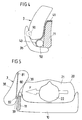
- FIG. 6 shows a modification of the embodiment of FIGS. 1 to 3 ,
- an airbag 3 with two fabric layers 38, 39, a back frame 11, a module carrier 40 ', a gas generator 50, an additional fabric layer 31' and an attachment 60 'for connecting the additional fabric layer 31' provided with the back frame 11 ,
- the additional fabric layer 31 'to the airbag 3 or its fabric layer 39 two seams 36', 36a 'are provided.
- the one seam 36a ' extends adjacent to and thus substantially congruent with the attachment 60' and provided by the attachment 60 ', perpendicular to the image plane extending attachment line between the airbag 3 and the back frame 11.
- the further seam 36 ' connects an edge region of the additional fabric layer 31' to the gas bag.
- the further seam 36 ' can be formed circumferentially, so that even in the rear direction in the direction of travel (adjacent to the module carrier 40') there is a connection between additional fabric layer 31 'and airbag 3.
- additional seams may be present.
- the attachment 60 ' is formed, for example, by means of screws or bolts and, in one embodiment, passes through the layer 312' facing away from the gas bag 3 as well as the module carrier 40 '. Corresponding screws or bolts can be preassembled on the module carrier 40 '. In other embodiments, the attachment 60 'passes through both layers 311', 312 'of the additional tissue mounts 31' and the module carrier 40 '.
- the airbag 3 is in the embodiment of FIG. 4 from two sub-chambers, one extending in the direction of travel main chamber 3a, which is filled in the case of release alone directly with the gas of the gas generator 50 and an associated with the main chamber 3a auxiliary chamber 3b.
- the additional chamber 3b closes on the side facing away from the direction of travel of the main chamber 3a to this.
- the additional chamber 3b is now shaped such that it covers the vehicle seat at its side facing away from the direction of travel, ie the rear side laterally at least partially in the manner of a claw.
- the additional chamber 3b and the encompassing of the seat back of the airbag 3 is additionally stabilized in total, so that the main chamber 3a has a higher buckling resistance and positional stability upon impact of a vehicle occupant.
- the additional chamber 3b is preferably formed sickle-shaped in cross-section or boomerang-shaped, whereby embracing the back of the vehicle seat is particularly effective possible.
- the flow connection 90 between the two chambers 3a, 3n can basically be designed in any desired manner.
- the existing representation is only to be understood schematically.
- a proboscis can project into the other chamber 3b, via which gas is introduced into the additional chamber 3b from a certain internal pressure in the main chamber 3a.
- an additional chamber 3b also a plurality of additional chambers may be provided, either all the additional chambers are filled by the main chamber 3a or another additional chamber is filled by an additional chamber previously filled by the main chamber.
- tether 80 not only a tether 80, but a plurality of tethers are provided, which may be parallel or intersecting formed.
- the gas generator 50 is located behind the gas bag 3 and the tube 51 is bent out of the image plane.
- the gas generator 50 is partially or completely disposed within the airbag 3.
- the outlet opening of the gas generator 50 (not shown) is located inside the airbag 3.
- the one end of the gas generator 50 is in the embodiment of FIG. 8 outside of the gas bag, however, may alternatively also be arranged in the gas bag 3.
- this has a slot 301 in one of its layers.
- the gas bag 3 is attached directly to the gas generator 50, for example by means of a clamping connection.
- the folded airbag fabric lies in one embodiment in the x-direction (ie in the direction of travel) in front of the filling element. This will ensure that the unfolding is directed primarily in the x-direction. Otherwise, there would be the risk that the airbag is deploying too much in the direction of the interior (y-direction).
- FIGS. 1 to 3 , of the FIG. 4 and the FIG. 5 can also be combined.
- the gas bag of FIG. 1 or the FIG. 6 a tether 80 corresponding to FIG. 5 or an additional chamber 3b according to the FIG. 4 form.
Abstract
Description
Die Erfindung betrifft ein Fahrzeuginsassen-Rückhaltesystem mit einem in einem Fahrzeugsitz angeordneten aufblasbaren Gassack gemäß dem Oberbegriff des Patentanspruchs 1.The invention relates to a vehicle occupant restraint system having an inflatable airbag arranged in a vehicle seat according to the preamble of patent claim 1.
Es besteht allgemein das Bedürfnis, Fahrzeuginsassen-Rückhaltesysteme bereitzustellen, die bei einem Seitenaufprall den stoßabgewandten Insassen mittels eines Gassacks im Sitz halten, um Verletzungen des Insassen durch Kontakt mit dem Fahrzeuginterieur oder anderen Insassen zu vermeiden. Statistiken zeigen dabei, dass ca. 27 bis 30 Prozent der Getöteten oder Schwerverletzten im Seitencrashfall auf der stoßabgewandten Seite saßen.There is a general need to provide vehicle occupant restraint systems that, in a side impact, hold the occupant away from the impact by means of a gas bag in the seat to prevent injury to the occupant by contact with the vehicle interior or other occupants. Statistics show that about 27 to 30 percent of those killed or seriously injured sat in a side crash case on the side facing away from the impact.
Aus der
Weiter ist es zum Schutz eines Insassen bei einem Seitenaufprall bekannt, eine Kombination aus einem Dreipunkt-Gurt und einem Zweipunkt-Gurt oder auch Vierpunkt- und Fünfpunkt-Gurtsysteme zu verwenden. Solche Gurtsysteme weisen den Nachteil auf, dass der gewohnte Komfort beim Anlegen eines gewöhnlichen Dreipunkt-Gurtes nicht mehr vorhanden ist und daher das Risiko besteht, dass der Insasse den Sicherheitsgurt überhaupt nicht anlegt.Further, in order to protect an occupant in a side impact, it is known to use a combination of a three-point belt and a two-point belt, or four-point and five-point belt systems. Such harness systems have the disadvantage that the usual comfort when creating a common three-point belt is no longer present and therefore there is a risk that the occupant does not apply the seat belt at all.
Die
Der vorliegenden Erfindung liegt die Aufgabe zugrunde, ein Fahrzeuginsassen-Rückhaltesystem mit einem in einem Fahrzeugsitz angeordneten aufblasbaren Gassack zur Verfügung zu stellen, das eine Seitwärtsbewegung oder schräge Vorwärtsbewegung eines Fahrzeuginsassen einschränkt und dabei möglichst knicksteif ausgebildet ist. Insbesondere soll das Fahrzeuginsassen-Rückhaltesystem ermöglichen, dass sich der stoßabgewandte Insasse während eines Seitenaufpralls nicht aus dem Bereich seines Sitzes hinaus bewegen kann und somit ein Kontakt des Insassen mit anderen Insassen oder dem Fahrzeuginterieur verhindert oder zumindest reduziert wird. Dabei soll ein kombinierte Nutzung des Fahrzeuginsassen-Rückhaltesystems mit einem üblichen Dreipunkt-Gurtsystem möglich sein.The present invention has for its object to provide a vehicle occupant restraint system with an arranged in a vehicle seat inflatable airbag available that limits a sideways movement or oblique forward movement of a vehicle occupant and is formed as kink-resistant. In particular, the vehicle occupant restraint system is intended to allow the shock-deflected occupant to not move out of the region of his seat during a side impact and thus prevent or at least reduce contact of the occupant with other occupants or the vehicle interior. In this case, a combined use of the vehicle occupant restraint system with a conventional three-point belt system should be possible.
Die vorliegende Aufgabe wird erfindungsgemäß durch ein Fahrzeuginsassen-Rückhaltesystem mit den Merkmalen des Anspruchs 1 gelöst. Bevorzugte und vorteilhafte Ausgestaltungen der Erfindung sind in den Unteransprüchen angegeben.The present object is achieved by a vehicle occupant restraint system with the features of claim 1. Preferred and advantageous embodiments of the invention are specified in the subclaims.
Danach zeichnet sich die Erfindung dadurch aus, einen Gassack des Fahrzeuginsassen-Rückhaltesystems an dem in Fahrtrichtung vorderen Ende des Lehnenrahmens mit diesem zu verbinden. Die Verbindung des Gassacks mit dem Lehnenrahmen erfolgt dabei mittels einer Zusatz-Gewebelage, die zum einen mit dem Gassack und zum anderen mit dem vorderen Ende des Lehnenrahmens verbunden ist. Die gebildete Verbindung des Gassacks mit dem Lehnenrahmen erfolgt entlang einer Verbindungslinie, die sich entsprechend der Form des Lehnenrahmens im Wesentlichen in vertikaler Richtung erstreckt.Thereafter, the invention is characterized by connecting a gas bag of the vehicle occupant restraint system at the front end in the direction of travel of the back frame with this. The connection of the gas bag with the back frame is carried out by means of an additional fabric layer, which is connected to the one with the gas bag and the other with the front end of the back frame. The formed connection of the gas bag with the back frame takes place along a connecting line which extends according to the shape of the back frame substantially in the vertical direction.
Es ist bekannt, dass sich an den beiden Seiten eines Fahrzeugsitzes jeweils ein Lehnenrahmen erstreckt, wobei der Lehnenrahmen im Wesentlichen in Fahrtrichtung ausgerichtet ist und dementsprechend ein vorderes, in Fahrtrichtung weisendes und ein hinteres, der Fahrtrichtung abgewandtes Ende aufweist. Das vordere Ende des Lehnenrahmens umfasst zum einen die in Fahrtrichtung weisende Stirnseite des Lehnenrahmens. Das vordere Ende des Lehnenrahmens umfasst jedoch auch Bereiche des Lehnenrahmens, die an die Stirnseite angrenzen. Ein vorderes Ende im Sinne der vorliegenden Erfindung liegt dabei solange vor, wie der Abstand zwischen der Verbindungsstruktur zur Befestigung des Gassackes am Lehnenrahmen und der Stirnseite des Lehnenrahmens nicht größer ist als die Hälfte des Abstandes zwischen der Stirnseite und dem in Fahrtrichtung hinteren Ende des Lehnenrahmens. Die Verbindungsstruktur ist also in der vorderen Hälfte des Lehnenrahmens angeordnet. In einer Ausgestaltung beträgt der Abstand zwischen der Verbindungsstruktur zur Befestigung des Gassackes am Lehnenrahmen und der Stirnseite des Lehnenrahmens nicht mehr als ein Viertel des Abstandes zwischen der Stirnseite und dem in Fahrtrichtung hinteren Ende des Lehnenrahmens.It is known that in each case a back frame extends on both sides of a vehicle seat, wherein the back frame is oriented substantially in the direction of travel and accordingly has a front, pointing in the direction of travel and a rear, facing away from the direction of travel end. The front end of the backrest frame comprises on the one hand facing in the direction of travel front side of the backrest frame. However, the front end of the backrest frame also includes areas of the backrest frame, which adjoin the front side. A front end in the sense of the present invention is present as long as the distance between the Connection structure for attaching the airbag to the back frame and the front of the back frame is not greater than half the distance between the front and the rear end of the back frame in the direction of travel. The connection structure is thus arranged in the front half of the backrest frame. In one embodiment, the distance between the connection structure for fastening the airbag to the backrest frame and the front side of the backrest frame is not more than a quarter of the distance between the front side and the rear end of the backrest frame in the direction of travel.
Durch die Bereitstellung der Verbindung des Gassacks mit dem Lehnenrahmen an dem in Fahrtrichtung vorderen Ende des Lehnenrahmens wird zum einen eine Entfaltung des Gassackes in Fahrtrichtung erleichtert und eine möglichst weit gegenüber der Rückenlehne des Fahrzeugsitzes vorstehende Gassackform ermöglicht. Zum anderen kann sich der mit dem Lehnenrahmen verbundene Gassack an diesem abstützen, so dass der Gassack insgesamt hinsichtlich seiner Position stabilisiert und gestützt wird. Dies führt dazu, dass die erfindungsgemäße Lösung eine Seitwärtsbewegung oder schräge Vorwärtsbewegung eines Insassen im Falle eines Seitenaufpralls weitgehend einschränken kann. Die bereitgestellte Lösung kann dabei problemlos mit üblichen Dreipunkt-Gurtsystemen zusammenwirken.By providing the connection of the gas bag with the back frame on the front end in the direction of travel of the backrest frame, a deployment of the airbag in the direction of travel is facilitated and allows as far as possible against the backrest of the vehicle seat gas bag shape. On the other hand, the gas bag connected to the back frame can be supported on this, so that the gas bag is stabilized and supported overall with respect to its position. As a result, the solution according to the invention can largely restrict sideways movement or oblique forward movement of an occupant in the event of a side impact. The solution provided can easily interact with conventional three-point belt systems.
Im Vordergrund der Erfindung steht die Bereitstellung eines möglichst knicksteifen Gassacks, der eine Seitwärtsbewegung oder schräge Vorwärtsbewegung eines Fahrzeuginsassens bei einem Seitenaufprall sicher einschränkt. Primär von Bedeutung ist daher die Funktion des Gassacks der Rückhaltung eines Fahrzeuginsassen. Die Funktion der Energieabsorption durch den Gassack ist von lediglich sekundärer Bedeutung. Dementsprechend ist bevorzugt vorgesehen, einen hohen Druck von circa 2 Bar in dem Gassack zu verwirklichen und diesen gasdicht, d.h. ohne Luftausströmöffnungen auszubilden.In the foreground of the invention is the provision of a kink-resistant as possible gas bag, which restricts a sideways movement or oblique forward movement of a vehicle occupant in a side impact safely. Of primary importance is therefore the function of the gas bag, the restraint of a vehicle occupant. The function of energy absorption by the gas bag is of only secondary importance. Accordingly, it is preferably provided to realize a high pressure of about 2 bar in the gas bag and to make it gas-tight, i. without air outlets form.
Erfindungsgemäß erfolgt die Verbindung des Gassacks mit dem Lehnenrahmen entlang einer Verbindungslinie, die sich entsprechend der Form des Lehnenrahmens im Wesentlichen in vertikaler Richtung erstreckt. Der Gassack ist dabei entlang der Verbindungslinie beispielsweise mittels einer Mehrzahl von Befestigungsstellen (z.B. Verschraubungen) mit dem Lehnenrahmen verbunden. Es ergibt sich eine vertikale Struktur des Gassacks im Bereich der Lehnenanbindung, wodurch sich der Gassack im Bereich des Lehnenrahmens sicher und über eine definierte vertikale Länge an diesem abstützen kann.According to the invention, the connection of the gas bag with the back frame along a connecting line, which extends in accordance with the shape of the back frame substantially in the vertical direction. The gas bag is connected along the connecting line, for example by means of a plurality of fastening points (eg screw) with the back frame. The result is a vertical structure of the gas bag in the region of the Lehnenanbindung, whereby the gas bag in the region of the backrest frame can be supported safely and over a defined vertical length of this.
Erfindungsgemäß erfolgt des Weiteren die Verbindung des Gassacks mit dem Lehnenrahmen mittels einer Zusatz-Gewebelage, die zum einen mit dem Gassack und zum anderen mit dem vorderen Ende des Lehnenrahmens verbunden ist. Die Verbindung der Zusatz-Gewebelage mit dem Gassack erfolgt beispielsweise über ein Vernähen der Zusatz-Gewebelage und mit einer der Gewebelagen des Gassacks, wobei das Vernähen zumindest entlang des Umfangs der Zusatz-Gewebelage erfolgt. Alternativ kann auch vorgesehen sein, dass die Zusatz-Gewebelage mit einer der Gewebelagen des Gassacks verklebt ist, entweder entlang ihres Randbereiches oder über ihre vollständige Fläche.According to the invention, furthermore, the connection of the gas bag to the back frame is effected by means of an additional fabric layer, which is connected on the one hand to the gas bag and on the other hand to the front end of the back frame. The connection of the additional fabric layer with the gas bag is effected, for example, by sewing the additional fabric layer and with one of the fabric layers of the gas bag, the sewing taking place at least along the circumference of the additional fabric layer. Alternatively, it can also be provided that the additional fabric layer is glued to one of the fabric layers of the gas bag, either along its edge region or over its entire surface.
Die Verwendung einer Zusatz-Gewebelage zur Befestigung des Gassacks an dem vorderen Ende des Lehnenrahmens ermöglicht zum einen eine einfache unmittelbare Verbindung des Gassacks mit dem Lehnenrahmen. Zum anderen bildet der Gassack im Bereich der Anbringung der Zusatz-Gewebelage aufgrund der übereinander liegenden Gewebelagen einen besonders stabilen und knicksteifen Teilbereich aus, der sich gut an dem Lehnenrahmen abstützen und darüber hinaus auch andere Bereiche oder Teilkammern des Gassacks stabilisieren und positionieren kann.The use of an additional fabric layer for fastening the gas bag to the front end of the back frame allows for a simple direct connection of the gas bag with the back frame. On the other hand, the gas bag in the region of attachment of the additional fabric layer forms a particularly stable and kink-resistant portion due to the superposed fabric layers, which support well on the back frame and beyond stabilize and position other areas or sub-chambers of the gas bag.
Zur Verbindung der Zusatz-Gewebelage mit dem vorderen Ende des Lehnenrahmens ist die Zusatz-Gewebelage beispielsweise um ein mit dem vorderen Ende des Lehnenrahmens verbundenes Halteteil geführt, das beispielsweise an der Stirnseite des Lehnenrahmens mit diesem verschraubt ist. Hierdurch wird in einfacher Weise über eine definierte vertikale Länge eine Anbindung des Gassackes an das vordere Ende des Lehnenrahmens erreicht.To connect the additional fabric layer to the front end of the backrest frame, the additional fabric layer is guided, for example, around a holding part connected to the front end of the backrest frame, which is screwed to the end face of the backrest frame for example. As a result, a connection of the airbag to the front end of the backrest frame is achieved in a simple manner over a defined vertical length.
In einer anderen Ausgestaltung bildet die Zusatz-Gewebelage eine Schlaufe aus.In another embodiment, the additional fabric layer forms a loop.
Das Fahrzeuginsassen-Rückhaltesystem weist bevorzugt einen Gassack-Modulträger zur Befestigung eines Gasgenerators sowie der Gassackverpackung mit dem gefalteten Gassack daran auf. Der Modulträger ist beispielsweise als gebogenes Blechteil ausgebildet. Es ist bevorzugt vorgesehen, dass auch ein solcher Modulträger an das vordere Ende des Lehnenrahmens angebunden ist. Dabei kann der Modulträger zusammen mit einem Halteteil, das der Befestigung der Zusatz-Gewebelage an dem Lehnenrahmen dient, mit dem Lehnenrahmen verbunden werden. Hierdurch wird eine einfache Konstruktion bereitgestellt. In einer anderen Ausgestaltung ist der Modulträger vollständig oder teilweise in eine Schlaufe oder Tasche eingeführt, die die Zusatz-Gewebelage ausbildet.The vehicle occupant restraint system preferably has an airbag module carrier for fastening a gas generator as well as the airbag packaging with the folded airbag thereto. The module carrier is formed, for example, as a bent sheet metal part. It is preferably provided that such a module carrier is connected to the front end of the back frame. In this case, the module carrier can be connected to the back frame together with a holding part, which serves to attach the additional fabric layer to the back frame. This provides a simple construction. In another embodiment, the module carrier fully or partially inserted into a loop or pocket which forms the additional fabric layer.
In bevorzugten Ausgestaltungen der Erfindung weist der Gassack eine oder mehrere Abnäher zur Ausbildung von einem oder mehreren nicht aufblasbaren Teilbereichen des Gassacks auf. Die Abnäher sind dabei bevorzugt derart ausgebildet, dass der Gassack mindestens eine knicksteife, im Wesentlichen vertikal verlaufende Säule und/oder mindestens eine knicksteife, im Wesentlichen horizontal verlaufende Säule ausbildet. Eine solche Säule bzw. mehrere solchen Säulen werden dabei durch den unmittelbar an den Lehnenrahmen angrenzenden Teilbereich des Gassacks stabilisiert und positioniert. Dabei stützt sich der Teilbereich des aufgeblasenen Gassacks, der mit der Zusatz-Gewebelage verbunden ist, wie erläutert am Lehnenrahmen ab und stellt dadurch eine Stabilisierung und Positionierung des Gassacks insgesamt bereit.In preferred embodiments of the invention, the gas bag has one or more darts for forming one or more non-inflatable portions of the gas bag. The darts are preferably designed such that the gas bag forms at least one buckling-resistant, substantially vertical column and / or at least one buckling-resistant, substantially horizontally extending column. Such a pillar or a plurality of such pillars are stabilized and positioned by the subregion of the airbag which is directly adjacent to the backrest frame. As explained, the partial region of the inflated gas bag, which is connected to the additional fabric layer, is supported on the backrest frame, thereby providing stabilization and positioning of the gas bag as a whole.
Die Erfindung wird nachfolgend unter Bezugnahme auf die Figuren anhand mehrerer Ausführungsbeispiele näher erläutert. Es zeigen:
- Figur 1
- in Schnittansicht ein Ausführungsbeispiel eines Fahrzeuginsassen- Rückhaltesystems, bei dem ein Gassack mit dem vorderen Ende eines Lehnenrahmen verbunden ist;
- Figur 2
- eine Darstellung des Details "X" der
Figur 1 ; Figur 3- eine Seitenansicht des Fahrzeuginsassen-Rückhaltesystems der
Figuren 1 und 2 ; - Figur 4
- in Schnittansicht ein Ausführungsbeispiel eines Fahrzeuginsassen- Rückhaltesystems, bei dem ein Gassack eine Hauptkammer und eine Zusatzkammer aufweist, die in Strömungsverbindung mit der Hauptkammer steht und sich an der der Fahrtrichtung abgewandten Seite der Hauptkammer an diese anschließt;
- Figur 5
- in Schnittansicht ein Ausführungsbeispiel eines Fahrzeuginsassen- Rückhaltessystems, bei dem im Inneren eines Gassacks ein Fangband die beiden Lagen des Gassacks miteinander verbindet;
- Figur 6
- in Schnittansicht ein weiteres Ausführungsbeispiel eines Fahrzeuginsassen- Rückhaltesystems, bei dem ein Gassack mit dem vorderen Ende eines Lehnenrahmen verbunden ist;
- Figur 7
- ein Ausführungsbeispiel für die Anordnung eines Gasgenerators; und
- Figur 8
- ein weiteres Ausführungsbeispiel für die Anordnung eines Gasgenerators.
- FIG. 1
- in sectional view an embodiment of a vehicle occupant restraint system in which a gas bag is connected to the front end of a back frame;
- FIG. 2
- a representation of the detail "X" of the
FIG. 1 ; - FIG. 3
- a side view of the vehicle occupant restraint system of
Figures 1 and 2 ; - FIG. 4
- in sectional view an embodiment of a vehicle occupant restraint system in which a gas bag has a main chamber and an additional chamber, which is in fluid communication with the main chamber stands and adjoins the side facing away from the direction of travel of the main chamber to this;
- FIG. 5
- in a sectional view of an embodiment of a vehicle occupant restraint system, wherein in the interior of a gas bag, a tether connects the two layers of the airbag together;
- FIG. 6
- in a sectional view of another embodiment of a vehicle occupant restraint system in which a gas bag is connected to the front end of a back frame;
- FIG. 7
- an embodiment of the arrangement of a gas generator; and
- FIG. 8
- a further embodiment of the arrangement of a gas generator.
Die
Ein Fahrzeugsitz 10 weist allgemein im Bereich seiner Rückenlehne an den beiden Seiten der Rückenlehne jeweils einen Lehnenrahmen auf, von denen der eine Lehnenrahmen 11 in der
Die beiden Lehnenrahmen eines Fahrzeugsitzes stellen eine Rahmenstruktur bereit, an der weitere Komponenten des Sitzes in an sich bekannter Weise direkt oder indirekt befestigt sind. Die Lehnenrahmen erstrecken sich dabei im Wesentlichen in vertikaler Richtung im Fahrzeugsitz. Das Querschnittsprofil ist gemäß der
Der Gassack 3 weist flach ausgebreitet im entfalteten, nicht aufgeblasenen Zustand zwei übereinander liegende Gewebelagen 38, 39 auf. Nach Aufblasen des Gassackes sind diese beiden Gewebelagen 38, 39 voneinander beabstandet und bilden zwischen sich das Gassackvolumen aus. Es ist des Weiteren eine Zusatz-Gewebelage 31 vorgesehen, die mit der einen Gewebelage 39 des Gassacks 3 verbunden ist und einer Befestigung des Gassacks 3 an dem in Fahrtrichtung vorderen Ende des Lehnenrahmens 11 dient. Die Befestigung erfolgt über eine Befestigungsstruktur 32, die in Bezug auf die
Die
Bei einem Seitenaufprall erfährt der Fahrzeuginsasse 20, dessen Torso 21 und Kopf 22 dargestellt sind, eine in Richtung des Pfeils F wirkende Kraft, die dazu geeignet ist, den Fahrzeuginsassen aus dem Fahrzeugsitz 10 herauszuschleudern. Um dies zu vermeiden, ist der am Lehnenrahmen 11 befestigte Gassack 3 vorgesehen. Durch den Gassack wird eine Seitwärtsbewegung oder schräge Vorwärtsbewegung des Fahrzeuginsassen 20, bevorzugt in Zusammenspiel mit einem herkömmlichen DreiPunkt-Gurtsystem so weit eingeschränkt, dass sich der stoßabgewandte Fahrzeuginsasse 21 während des Seitenaufpralls nicht aus dem Bereich seines Sitzes hinaus bewegt und somit eine Verletzungsgefahr durch Kontakt mit Fahrzeugelementen oder anderen Fahrzeuginsassen verhindert oder reduziert wird. Für einen wirksamen Schutz des Fahrzeuginsassen ist es dabei vorteilhaft, wenn der Gassack 3 insgesamt möglichst stabil und knicksteif ausgebildet ist.In a side impact, the
Der Gassack 3 ist gemäß der
Gemäß der
Der Modulträger 40 ist an seinem der Stirnseite 12 des Lehnenrahmens 11 abgewandten Ende zur Aufnahme und Befestigung eines Gasgenerators 50 ausgebildet, der schematisch dargestellt ist. Der Gasgenerator 50 und der gefaltete Gassack 3 bilden zusammen mit dem Modulträger 40 und weiteren typischen Komponenten eines Gassackmoduls ein solches aus. Solche weiteren Komponenten sind z.B. ein Modulgehäuse, Airbagsensoren und eine Steuervorrichtung. Solche weiteren Elemente sind in den Figuren nicht gesondert dargestellt, da sie dem Fachmann wohl bekannt sind.The
Die
Die Zusatz-Gewebelage 31 ist entlang ihres Umfanges mit der entsprechenden Gewebelage 39 des Gassacks 3 verbunden. Zusätzlich kann optional eine Naht zwischen der Zusatz-Gewebelage 31 und der Gassack-Gewebelage 39 im Bereich der Anbindung der Zusatz-Gewebelage 31 an den Lehnenrahmen 11 erfolgen, damit der eigentliche Gassack 3 in diesem Anbindungsbereich eng an der Stirnseite 12 des Lehnenrahmens 11 geführt wird. Zur Darstellung einer solchen weiteren Naht ist in der
Weiter kann in einer alternativen Ausgestaltung auch vorgesehen sein, dass die Zusatz-Gewebelage 31 mit der entsprechenden Gewebelage 39 des Gassackes verklebt ist, entlang ihres Umfanges oder aber auch großflächig.Furthermore, it can also be provided in an alternative embodiment that the
Der Gassack 3 weist des Weiteren zwei Abnäher 33, 34 auf, die jeweils einen nicht aufblasbaren Teilbereich 330, 340 des Gassacks bilden.The
Bei Entfalten des Gassackes 3 bildet dieser in dem Bereich, der mit der Zusatz-Gewebelage 31 verbunden ist, einen hoch stabilisierten Teilbereich 360 aus, der sich am Lehnenrahmen 11 direkt abstützt und dadurch eine Stabilisierung und Positionierung des Gassackes 3 insgesamt bereitstellt. Durch Anbindung des Gassackes 3 am in Fahrtrichtung vorderen Ende des Lehnenrahmens 11 kann sich der Gassack 3 weit in Fahrtrichtung von der Rückenlehne 10 erstrecken, so dass auch bei einer schrägen Vorwärtsbewegung ein beschleunigter Fahrzeuginsasse zurückgehalten wird. Der Bereich 360 der Anbindung des Gassacks 3 an den Lehnenrahmen 11 stellt zusätzlich einen auf Grund der zusätzlichen Gewebelage 31 und der Abstützung direkt am Lehnenrahmen 11 stabilisierend und positionierend wirkenden Teilbereich dar.Upon deployment of the
Durch diese Stabilisierung und Positionierung ist es möglich, dass auch andere Teilbereiche des Gassackes stabilisiert werden. Insbesondere bildet im Ausführungsbeispiel der
Die
Anders als beim Ausführungsbeispiel der
Die Zusatz-Gewebelage 31' ist in dem Ausführungsbeispiel der
Zur Befestigung der Zusatz-Gewebelage 31' an dem Gassack 3 bzw. dessen Gewebelage 39 sind zwei Nähte 36', 36a' vorgesehen. Die eine Naht 36a' verläuft angrenzend zur und damit im Wesentlichen deckungsgleich mit der Befestigung 60' und die durch die Befestigung 60' bereitgestellte, senkrecht zur Bildebene verlaufende Befestigungslinie zwischen dem Gassack 3 und dem Lehnenrahmen 11. Hierdurch wird der aufgebasene Gassack 3 in vertikaler Richtung an dem Lehnenrahmen 33 ausgerichtet. Die weitere Naht 36' verbindet einen Randbereich der Zusatz-Gewebelage 31' mit dem Gassack. Die weitere Naht 36' kann dabei umlaufend ausgebildet sein, so dass auch im in Fahrtrichtung hinteren Bereich (angrenzend an den Modulträgers 40') eine Verbindung zwischen Zusatz-Gewebelage 31' und Gassack 3 vorliegt. In weiteren Ausgestaltungen können weitere Nähte vorhanden sein.To attach the
Die Befestigung 60' ist beispielsweise über durch Schrauben oder Bolzen ausgebildet und durchgreift in einer Ausgestaltung die dem Gassack 3 abgewandte Lage 312' sowie den Modulträger 40'. Entsprechende Schrauben oder Bolzen können dabei an dem Modulträger 40' vormontiert sein. In anderen Ausführungsvarianten durchgreift die Befestigung 60' beide Lagen 311', 312' der Zusatz-Gewebelöage 31' sowie den Modulträger 40'.The attachment 60 'is formed, for example, by means of screws or bolts and, in one embodiment, passes through the layer 312' facing away from the
Die
Der Gassack 3 besteht im Ausführungsbeispiel der
Die Zusatzkammer 3b ist nun derart geformt, dass sie den Fahrzeugsitz an seiner der Fahrtrichtung abgewandten, also hinteren Seite seitlich zumindest teilweise nach Art einer Kralle umfasst. Durch die Zusatzkammer 3b und deren Umgreifen der Sitzlehne wird der Gassack 3 insgesamt zusätzlich stabilisiert, so dass die Hauptkammer 3a eine höhere Knicksteifigkeit und Positionstreue bei Aufprall eines Fahrzeuginsassen aufweist.The additional chamber 3b is now shaped such that it covers the vehicle seat at its side facing away from the direction of travel, ie the rear side laterally at least partially in the manner of a claw. By the additional chamber 3b and the encompassing of the seat back of the
Die Zusatzkammer 3b ist bevorzugt im Querschnitt sichelförmig oder boomerang-förmig ausgebildet, wodurch ein Umgreifen der Rückseite des Fahrzeugsitzes besonders effektiv möglich ist.The additional chamber 3b is preferably formed sickle-shaped in cross-section or boomerang-shaped, whereby embracing the back of the vehicle seat is particularly effective possible.
Es wird darauf hingewiesen, dass die Strömungsverbindung 90 zwischen den beiden Kammern 3a, 3n grundsätzlich in beliebiger Weise ausgebildet sein kann. Die vorhandene Darstellung ist lediglich schematisch zu verstehen. Beispielsweise kann von der einen Kammer 3a ein Rüssel in die andere Kammer 3b ragen, über den ab einem bestimmten Innendruck in der Hauptkammer 3a Gas in die Zusatzkammer 3b geleitet wird.It should be noted that the
Weiter wird darauf hingewiesen, dass statt einer Zusatzkammer 3b auch mehrere Zusatzkammern vorgesehen sein können, wobei entweder sämtliche Zusatzkammern durch die Hauptkammer 3a befüllt werden oder aber eine weitere Zusatzkammer durch eine durch die Hauptkammer zuvor befüllte Zusatzkammer befüllt wird.It should also be noted that instead of an additional chamber 3b also a plurality of additional chambers may be provided, either all the additional chambers are filled by the main chamber 3a or another additional chamber is filled by an additional chamber previously filled by the main chamber.
Die
Zur Stabilisierung des Gassacks 3 und der Bereitstellung einer hohen Knicksteifigkeit gegenüber einem aufprallenden Insassen 20 ist im Inneren des Gassacks 3 ein Fangband 80 vorgesehen, das zum einen über einen Anbindungspunkt 81 mit der einen Gewebelage 38 und zum anderen über einen Anbindungspunkt 82 mit der anderen Gewebelage 39 verbunden ist. Das Fangband 80 erstreckt sich bevorzugt entsprechend der Darstellung der
In alternativen Ausführungsbeispielen sind nicht nur ein Fangband 80, sondern eine Vielzahl von Fangbändern vorgesehen, die parallel verlaufend oder auch sich kreuzend ausgebildet sein können.In alternative embodiments, not only a
Die Anordnung des Gasgenerators kann in den beschriebenen Ausführungsbeispielen auf verschiedene Weise erfolgen. In einer in der
Es wird darauf hingewiesen, dass in der Darstellung der
In einem weiteren, in der
Es wird darauf hingewiesen, dass das gefaltete Luftsackgewebe in einer Ausgestaltung in x-Richtung (also in Fahrtrichtung) vor dem Füllelement liegt. Hierdurch wird sichergestellt, dass die Entfaltung primär in x-Richtung gerichtet ist. Anderenfalls würde die Gefahr bestehen, dass der Luftsack sich zu sehr in Richtung des Innenraums (y-Richtung) entfaltet.It should be noted that the folded airbag fabric lies in one embodiment in the x-direction (ie in the direction of travel) in front of the filling element. This will ensure that the unfolding is directed primarily in the x-direction. Otherwise, there would be the risk that the airbag is deploying too much in the direction of the interior (y-direction).
Die Ausführungsbeispiele der
Claims (26)
- A vehicle occupant restraint system with a vehicle seat having an inflatable airbag (3) which is arranged in the vehicle seat (10) and which, in the event of triggering, unfolds at least partially in the direction of travel on that side of the vehicle seat (10) which faces toward the vehicle interior, with the vehicle seat (10) having a backrest frame (11) which extends in the vehicle seat (10) in a substantially vertical direction and which is aligned substantially in the direction of travel,
characterized in that
the airbag (3) is connected to the backrest frame (11) at the front end (12) thereof in the direction of travel, wherein the connection of the airbag (3) to the backrest frame (11) takes place by means of an auxiliary material layer (31, 31') which is connected firstly to the airbag (3) and secondly to the front end (12) of the backrest frame (11), and wherein the thereby formed connection of the airbag (3) to the backrest frame (11) takes place along a connecting line (37) which extends in a substantially vertical direction corresponding to the shape of the backrest frame (11). - The vehicle occupant restraint system as claimed in claim 1, characterized in that the connection of the airbag (3) to the backrest frame (11) takes place at that end side (12) of the backrest frame (11) which points in the direction of travel.
- The vehicle occupant restraint system as claimed in claim 1, characterized in that the connection of the airbag (3) to the backrest frame (11) takes place adjacent to that end side (12) of the backrest frame (11) which points in the direction of travel.
- The vehicle occupant restraint system as claimed in claim 1 or 3, characterized in that the spacing between the connecting structure (60') for fastening the airbag (3) to the backrest frame (11) and the end side (12) of the backrest frame (11) is not greater than half of the spacing between the end side (12) of the backrest frame (11) and the rear end (13) of the backrest frame (11) in the direction of travel.
- The vehicle occupant restraint system as claimed in one of the preceding claims, characterized in that the airbag (3) is connected to the backrest frame (11) along the connecting line (37) by means of a plurality of fastening points (32).
- The vehicle occupant restraint system as claimed in one of the preceding claims, characterized in that the connection of the auxiliary material layer (31) to the airbag (3) comprises a stitched connection of the auxiliary material layer (31) to one of the material layers (39) of the airbag (3) along its periphery.
- The vehicle occupant restraint system as claimed in one of the preceding claims, characterized in that the connection of the auxiliary material layer (31) to the airbag (3) comprises an adhesively bonded connection of the auxiliary material layer (31) to one of the material layers (39) of the airbag (3).
- The vehicle occupant restraint system as claimed in one of the preceding claims, characterized in that, for the connection of the auxiliary material layer (31) to the front end (12) of the backrest frame (11), the auxiliary material layer (31) is guided around a holding part (70) which is connected to the front end of the backrest frame (11).
- The vehicle occupant restraint system as claimed in claim 8, characterized in that the holding part (70) is screwed to the front end (12) of the backrest frame (11).
- The vehicle occupant restraint system as claimed in claim 8 or 9, characterized in that the holding part (70) is connected to that end side (12) of the backrest frame (11) which points in the direction of travel.
- The vehicle occupant restraint system as claimed in one of claims 1 to 8, characterized in that the auxiliary material layer (31') forms a loop with a layer (311') which faces toward the airbag (3) and a layer (312') which faces away from the airbag (3).
- The vehicle occupant restraint system as claimed in claim 11, characterized in that the auxiliary material layer (31') is connected to the backrest frame (11) adjacent to the end side (12) thereof.
- The vehicle occupant restraint system as claimed in one of the preceding claims, characterized in that an airbag module carrier (40) is also provided, which airbag module carrier (40) is likewise connected to the front end (12) of the backrest frame (11).
- The vehicle occupant restraint system as claimed in claim 13, if referred back to claim 8, characterized in that the module carrier (40) is connected together with the holding part (70) to the front end (12) of the backrest frame (11).
- The vehicle occupant restraint system as claimed in claim 13, if referred back to claim 11, characterized in that the module carrier (40) is arranged in the loop formed by the auxiliary material layer (31') and is connected together with at least one layer of the loop to the front end (12) of the backrest frame (11).
- The vehicle occupant restraint system as claimed in one of the preceding claims, characterized in that the airbag (3) has one or more darts (33, 34) in order to form one or more non-inflatable partial regions (330, 340) of the airbag (3).
- The vehicle occupant restraint system as claimed in one of the preceding claims, characterized in that the airbag (3) forms at least one buckling-resistant, substantially vertically-running column (350).
- The vehicle occupant restraint system as claimed in one of the preceding claims, characterized in that the airbag (3) forms at least one buckling-resistant, substantially horizontally-running column (370).
- The vehicle occupant restraint system as claimed in one of the preceding claims, characterized in that that region (360) of the inflated airbag (3) which is connected to the auxiliary material layer (31) is supported on the backrest frame (11) and thereby provides stabilization and positioning of the airbag (3).
- The vehicle occupant restraint system as claimed in one of the preceding claims, characterized in that the inflated airbag (3) has a main chamber (3a) and at least one auxiliary chamber (3b), with the main chamber (3a) being connected to the backrest frame (11) at the front end of the latter in the direction of travel, and with the auxiliary chamber (3b) adjoining that side of the main chamber (3a) which faces away from the direction of travel and being flow-connected to the main chamber (3a).
- The vehicle occupant restraint system as claimed in claim 20, characterized in that the at least one auxiliary chamber (3b) at least partially engages laterally around the vehicle seat (10) at that side of the latter which faces away from the direction of travel.
- The vehicle occupant restraint system as claimed in one of the preceding claims, characterized in that the airbag (3) has at least one check strap (80) which runs in the interior of the airbag (3) and which, in the inflated state, connects a first layer (38) of the airbag and a second layer (39) of the airbag to one another.
- The vehicle occupant restraint system as claimed in claim 22, characterized in that the check strap (80) extends substantially in the direction of travel in the inflated airbag.
- The vehicle occupant restraint system as claimed in one of the preceding claims, characterized in that the gas internal pressure in the inflated airbag (3) is over 1.5 bar, and is particularly preferably approximately 2 bar.
- The vehicle occupant restraint system as claimed in one of the preceding claims, characterized in that the airbag (3) has no gas outlet openings.
- The vehicle occupant restraint system as claimed in one of the preceding claims, characterized in that the folded airbag (3), which is connected to the front end (12) of the backrest frame (11) over a defined length, is stored in the vehicle seat (10) in a substantially vertical direction along the backrest frame (11).
Applications Claiming Priority (2)
| Application Number | Priority Date | Filing Date | Title |
|---|---|---|---|
| DE102005059197A DE102005059197B4 (en) | 2005-12-06 | 2005-12-06 | Vehicle occupant restraint systems having an inflatable airbag disposed in a vehicle seat |
| PCT/EP2006/011704 WO2007065650A2 (en) | 2005-12-06 | 2006-12-06 | Passenger restraint system comprising an inflatable air bag and arranged in a vehicle seat |
Publications (2)
| Publication Number | Publication Date |
|---|---|
| EP1957325A2 EP1957325A2 (en) | 2008-08-20 |
| EP1957325B1 true EP1957325B1 (en) | 2011-02-16 |
Family
ID=37903447
Family Applications (1)
| Application Number | Title | Priority Date | Filing Date |
|---|---|---|---|
| EP06829336A Expired - Fee Related EP1957325B1 (en) | 2005-12-06 | 2006-12-06 | Passenger restraint system comprising an inflatable air bag and arranged in a vehicle seat |
Country Status (7)
| Country | Link |
|---|---|
| US (3) | US7819423B2 (en) |
| EP (1) | EP1957325B1 (en) |
| JP (1) | JP5164851B2 (en) |
| CN (1) | CN101326081B (en) |
| AU (1) | AU2006322173B2 (en) |
| DE (2) | DE102005059197B4 (en) |
| WO (1) | WO2007065650A2 (en) |
Families Citing this family (44)
| Publication number | Priority date | Publication date | Assignee | Title |
|---|---|---|---|---|
| DE102005062849A1 (en) * | 2005-12-23 | 2007-09-06 | Takata-Petri Ag | Occupant restraint device for a motor vehicle |
| DE102007044824B4 (en) * | 2007-09-20 | 2019-07-04 | Autoliv Development Ab | Safety device for a motor vehicle seat and motor vehicle seat |
| DE102007056848B4 (en) * | 2007-11-26 | 2018-10-11 | GM Global Technology Operations LLC (n. d. Ges. d. Staates Delaware) | Side airbag system, backrest and headrest |
| DE102008063794B4 (en) | 2008-12-17 | 2014-04-03 | TAKATA Aktiengesellschaft | Airbag for a vehicle occupant restraint system |
| DE102009007179B4 (en) * | 2008-12-18 | 2014-10-16 | TAKATA Aktiengesellschaft | A gas bag assembly for a vehicle occupant restraint system and method for protecting a vehicle occupant |
| KR101080728B1 (en) * | 2009-07-31 | 2011-11-07 | 현대자동차주식회사 | Side airbag apparatus for vehicles |
| CN102029968B (en) * | 2009-09-24 | 2015-11-25 | 马自达汽车株式会社 | Comprise the vehicle seat used of air bag device |
| US8186708B2 (en) * | 2010-03-08 | 2012-05-29 | Ford Global Technologies, Llc | Asymmetric side airbag for improved head and neck protection |
| DE102010027401B4 (en) * | 2010-07-15 | 2022-05-12 | Autoliv Development Ab | Side gas bag with lateral support |
| DE102010044611B4 (en) * | 2010-08-13 | 2019-05-09 | Autoliv Development Ab | Airbag with at least one connector |
| JP5961341B2 (en) * | 2011-02-25 | 2016-08-02 | 富士重工業株式会社 | Crew protection device |
| KR101283698B1 (en) * | 2011-03-29 | 2013-07-05 | 기아자동차주식회사 | Side air-bag for a vehicle |
| US8684408B2 (en) * | 2011-09-24 | 2014-04-01 | GM Global Technology Operations LLC | Side impact airbag cushion |
| DE102011087449B4 (en) | 2011-11-30 | 2019-04-25 | Autoliv Development Ab | Curtain airbag for a vehicle |
| KR101355594B1 (en) * | 2011-12-07 | 2014-01-29 | 현대자동차주식회사 | Dual chamber side air bag apparatus for vehicle |
| DE102013216178A1 (en) | 2012-09-19 | 2014-03-20 | Lear Corporation | Airbag module for a vehicle seat assembly |
| DE102012224178A1 (en) | 2012-12-21 | 2013-03-28 | Takata AG | Side airbag for motor vehicles, particularly for protecting vehicle occupants against a collision, has gas bag, which is arranged at vehicle seat so that gas bag is unfolded near vehicle occupant for protecting vehicle occupant |
| US8851511B1 (en) * | 2013-06-03 | 2014-10-07 | Key Safety Systems, Inc. | Shaped airbag |
| DE102014006862A1 (en) * | 2014-05-13 | 2015-11-19 | Trw Automotive Gmbh | Vehicle occupant protection device and vehicle seat |
| JP6197777B2 (en) * | 2014-10-10 | 2017-09-20 | トヨタ自動車株式会社 | Far-side airbag device for vehicles |
| DE102015108423A1 (en) * | 2015-05-28 | 2015-09-17 | Takata AG | Airbag for an airbag module |
| KR101781387B1 (en) * | 2016-04-15 | 2017-09-25 | 아우토리브 디벨롭먼트 아베 | Far side airbag apparatus for vehicle |
| JP6738416B2 (en) * | 2016-05-20 | 2020-08-12 | オートリブ ディベロップメント エービー | Side airbag device |
| JP6414157B2 (en) * | 2016-07-22 | 2018-10-31 | トヨタ自動車株式会社 | Vehicle occupant restraint system |
| JP6561942B2 (en) * | 2016-08-22 | 2019-08-21 | トヨタ自動車株式会社 | Vehicle seat with side airbag device |
| US10906494B1 (en) * | 2017-01-19 | 2021-02-02 | State Farm Mutual Automobile Insurance Company | Systems and methods for predicting occupant location based on vehicular collision |
| DE102017202868B4 (en) | 2017-02-22 | 2022-11-17 | Joyson Safety Systems Germany Gmbh | vehicle seats for motor vehicles |
| US10336278B2 (en) | 2017-07-14 | 2019-07-02 | Autoliv Asp, Inc. | Inflatable airbag harness assemblies |
| DE102017125755A1 (en) | 2017-11-03 | 2019-05-09 | Takata AG | The vehicle occupant restraint system |
| DE102018103071B4 (en) | 2017-11-15 | 2024-03-07 | Joyson Safety Systems Germany Gmbh | Gas bag for a vehicle occupant restraint system of a motor vehicle |
| US10703321B2 (en) | 2017-11-20 | 2020-07-07 | Ford Global Technologies, Llc | Airbag assembly |
| JP6762328B2 (en) * | 2018-02-14 | 2020-09-30 | オートリブ ディベロップメント エービー | Crew restraint device |
| DE102018202417A1 (en) * | 2018-02-16 | 2019-08-22 | Takata AG | The vehicle occupant restraint system |
| US10926733B2 (en) * | 2018-03-12 | 2021-02-23 | Ford Global Technologies, Llc | Vehicle including inflatable assembly supported by seat |
| DE102019203316A1 (en) | 2018-03-12 | 2019-09-12 | Lear Corporation | Occupant protection system for a vehicle seat |
| US20190275974A1 (en) * | 2018-03-12 | 2019-09-12 | Lear Corporation | Occupant protection systems for a vehicle seat |
| DE102018114771B4 (en) | 2018-06-20 | 2020-07-09 | Isi Automotive Holding Gmbh | Restraint device for reducing an abrupt sideways and forward movement of an occupant |
| EP3838689B1 (en) * | 2018-08-14 | 2024-01-03 | Autoliv Development AB | Side airbag device |
| JP7047701B2 (en) * | 2018-10-22 | 2022-04-05 | 豊田合成株式会社 | Side airbag device |
| US20200189513A1 (en) * | 2018-12-14 | 2020-06-18 | Key Safety Systems, Inc. | Far side crash mitigation |
| DE102019112344A1 (en) * | 2019-05-10 | 2020-11-12 | Autoliv Development Ab | VEHICLE SEAT ARRANGEMENT |
| US10988100B2 (en) | 2019-08-29 | 2021-04-27 | Ford Global Technologies, Llc | Side airbag including non-expandable region |
| DE102020118339A1 (en) * | 2020-07-10 | 2022-01-13 | Zf Automotive Germany Gmbh | vehicle occupant restraint system |
| DE102022104042A1 (en) | 2022-02-21 | 2023-08-24 | Faurecia Sieges D'automobile | Side airbag module for attachment to a frame of a seat backrest, method for its attachment and vehicle seat with side airbag module |
Family Cites Families (39)
| Publication number | Priority date | Publication date | Assignee | Title |
|---|---|---|---|---|
| US658838A (en) * | 1900-04-25 | 1900-10-02 | Joseph Fayolle | Alarm device for railway-tracks. |
| GB2232936B (en) * | 1989-06-13 | 1993-07-28 | Autoliv Dev | Improvements in or relating to an arrangement for protecting an occupant of a vehicle |
| GB2293355B (en) * | 1994-09-08 | 1997-12-17 | Alliedsignal Deutschland Gmbh | Inflatable safety restraint for vehicle occupant protection |
| US5651582A (en) * | 1994-12-20 | 1997-07-29 | Ikeda Bussan Co., Ltd. | Vehicular seat with side air-bag |
| US5503428A (en) * | 1995-02-03 | 1996-04-02 | Hoover Universal, Inc. | Vehicle seat with an inflatable air cushion |
| US5533750A (en) * | 1995-06-01 | 1996-07-09 | Takata, Inc. | Simplified inflatable restraint module |
| US5636862A (en) * | 1995-09-07 | 1997-06-10 | General Motors Corporation | Air bag assembly with tether |
| US5667241A (en) * | 1995-10-17 | 1997-09-16 | Morton International, Inc. | Seat mounted side impact airbags |
| US5564739A (en) * | 1995-12-07 | 1996-10-15 | Takata, Inc. | Side impact airbag module with soft cover |
| DE29601497U1 (en) * | 1996-01-29 | 1996-05-30 | Trw Repa Gmbh | Airbag side impact protection device |
| JP3357937B2 (en) * | 1996-02-07 | 2002-12-16 | 豊田合成株式会社 | How to fold the side airbag |
| US5630616A (en) * | 1996-02-14 | 1997-05-20 | Lear Seating Corporation | Seat frame integrated air bag inflator |
| DE19635495A1 (en) * | 1996-09-02 | 1998-03-05 | Pars Passive Rueckhaltesysteme | Restraint mechanism for side-airbag module of motor vehicle |
| JPH10100828A (en) * | 1996-09-27 | 1998-04-21 | Mazda Motor Corp | Side air bag device for vehicle |
| JP3722562B2 (en) * | 1996-09-27 | 2005-11-30 | デルタ工業株式会社 | Energy absorption structure on the side of the vehicle |
| US5890733A (en) * | 1996-10-24 | 1999-04-06 | Alliedsignal Inc. | Hook and snap side air bag module attachment |
| DE19746387B4 (en) * | 1996-10-25 | 2004-06-24 | Honda Giken Kogyo K.K. | airbag device |
| US5779263A (en) * | 1997-01-21 | 1998-07-14 | Alliedsignal Inc. | Integrated side impact air bag system within a seat structure |
| GB2322338B (en) * | 1997-02-20 | 2001-03-14 | Autoliv Dev | Improvements in or relating to an air-bag arrangement |
| US5890734A (en) * | 1997-03-07 | 1999-04-06 | Morton International, Inc. | Integral cover-deployment chute for side airbag module |
| JP3399280B2 (en) * | 1997-03-17 | 2003-04-21 | 三菱自動車工業株式会社 | Seat structure with side airbag |
| US5752714A (en) * | 1997-04-03 | 1998-05-19 | Morton International, Inc. | Side-impact airbag assembly |
| FR2761941B1 (en) * | 1997-04-09 | 1999-06-18 | Faure Bertrand Equipements Sa | VEHICLE SEAT WITH LATERAL INFLATABLE SAFETY BAG |
| EP0940299B1 (en) * | 1997-09-19 | 2005-01-19 | Nissan Motor Company, Limited | Air bag device for side collision of automobile |
| US6302431B1 (en) * | 1997-09-19 | 2001-10-16 | Nissan Motor Co., Ltd. | Air bag device |
| US6189916B1 (en) * | 1998-12-15 | 2001-02-20 | Trw Vehicle Safety Systems Inc. | Air bag module with deployment door |
| US6382665B2 (en) * | 1999-03-05 | 2002-05-07 | Magna Seating Systems Inc. | Self aligning and locking fastener |
| US6126192A (en) * | 1999-03-10 | 2000-10-03 | Autoliv Asp, Inc. | No fasteners side air bag module |
| US6386577B1 (en) * | 1999-03-29 | 2002-05-14 | Honda Giken Kogyokabushiki Kaisha | Side-collision air bag device |
| GB2357999B (en) * | 2000-01-05 | 2003-05-14 | Autoliv Dev | Improvements in or relating to an air-bag arrangement |
| DE60018158T8 (en) * | 2000-02-01 | 2006-08-24 | Delphi Automotive Systems Sungwoo Corp. | Side airbag system and its manufacturing process |
| US6588838B1 (en) * | 2000-03-23 | 2003-07-08 | Lear Corporation | Reinforced seat cover |
| DE10106238B4 (en) * | 2001-02-10 | 2012-09-13 | Volkswagen Ag | Safety device for a vehicle, in particular for a motor vehicle |
| US20030168836A1 (en) * | 2002-03-11 | 2003-09-11 | Eiji Sato | Side airbag apparatus |
| GB2397047B (en) * | 2003-01-10 | 2006-02-22 | Autoliv Development Ab | Improvements in or relating to vehicle air-seats and air-bag units |
| JP2004217184A (en) * | 2003-01-17 | 2004-08-05 | Toyoda Gosei Co Ltd | Airbag device for side collision |
| JP4313641B2 (en) * | 2003-10-17 | 2009-08-12 | 本田技研工業株式会社 | Side airbag device |
| DE102004020643A1 (en) * | 2004-04-22 | 2005-11-17 | Takata-Petri (Ulm) Gmbh | safety device |
| JP4465512B2 (en) * | 2004-06-30 | 2010-05-19 | テイ・エス テック株式会社 | Automotive seat with light alloy frame with airbag module |
-
2005
- 2005-12-06 DE DE102005059197A patent/DE102005059197B4/en not_active Expired - Fee Related
-
2006
- 2006-12-06 AU AU2006322173A patent/AU2006322173B2/en not_active Ceased
- 2006-12-06 EP EP06829336A patent/EP1957325B1/en not_active Expired - Fee Related
- 2006-12-06 WO PCT/EP2006/011704 patent/WO2007065650A2/en active Application Filing
- 2006-12-06 CN CN200680046136XA patent/CN101326081B/en not_active Expired - Fee Related
- 2006-12-06 JP JP2008543718A patent/JP5164851B2/en not_active Expired - Fee Related
- 2006-12-06 DE DE502006008921T patent/DE502006008921D1/en active Active
-
2008
- 2008-06-05 US US12/155,556 patent/US7819423B2/en not_active Expired - Fee Related
-
2010
- 2010-09-22 US US12/923,443 patent/US8091920B2/en not_active Expired - Fee Related
-
2012
- 2012-01-09 US US13/346,608 patent/US8256796B2/en not_active Expired - Fee Related
Also Published As
| Publication number | Publication date |
|---|---|
| WO2007065650A3 (en) | 2007-09-13 |
| US8091920B2 (en) | 2012-01-10 |
| JP2009518220A (en) | 2009-05-07 |
| WO2007065650A2 (en) | 2007-06-14 |
| AU2006322173B2 (en) | 2010-06-17 |
| EP1957325A2 (en) | 2008-08-20 |
| DE102005059197A1 (en) | 2007-07-19 |
| US7819423B2 (en) | 2010-10-26 |
| US20120139211A1 (en) | 2012-06-07 |
| US8256796B2 (en) | 2012-09-04 |
| DE102005059197B4 (en) | 2008-04-10 |
| CN101326081B (en) | 2010-12-29 |
| US20110012326A1 (en) | 2011-01-20 |
| AU2006322173A1 (en) | 2007-06-14 |
| JP5164851B2 (en) | 2013-03-21 |
| DE502006008921D1 (en) | 2011-03-31 |
| CN101326081A (en) | 2008-12-17 |
| US20090014990A1 (en) | 2009-01-15 |
Similar Documents
| Publication | Publication Date | Title |
|---|---|---|
| EP1957325B1 (en) | Passenger restraint system comprising an inflatable air bag and arranged in a vehicle seat | |
| DE102018114771B4 (en) | Restraint device for reducing an abrupt sideways and forward movement of an occupant | |
| DE60018158T2 (en) | Side airbag system and its manufacturing process | |
| DE102019124091A1 (en) | Airbag assembly for a vehicle occupant restraint system | |
| DE102011051318B4 (en) | INTERNAL AIRBAG DEVICE | |
| DE102008060729B4 (en) | Airbag cushion with multiple chambers | |
| EP2424750B1 (en) | Airbag module for protecting the thorax and head areas of a vehicle occupant | |
| WO2019166268A1 (en) | Airbag module and system for restraining vehicle occupants | |
| DE102008030188A1 (en) | Multi-chamber side airbag | |
| DE202006010878U1 (en) | Airbag arrangement for vehicle occupant restraint system has chamber section that extends forward when airbag inflated to protect occupant including for forward occupant movements at angle by catching associated occupant body regions | |
| DE102016224858A1 (en) | Curtain airbag for a vehicle | |
| DE102009006879A1 (en) | Side impact air bag system | |
| DE102018202417A1 (en) | The vehicle occupant restraint system | |
| WO2019197164A1 (en) | Airbag arrangement for a vehicle occupant restraint system | |
| DE112018006758T5 (en) | Driver airbag | |
| DE102004026313B4 (en) | Overhead airbag system | |
| EP0889808B1 (en) | Inflatable head-protection system for the side region of a passenger car | |
| EP1514744A2 (en) | Occupant restraint system located in the rear passenger compartment of a vehicle | |
| DE102014100550B4 (en) | Product comprising a vehicle with a roof frame airbag | |
| DE102014014028A1 (en) | A vehicle occupant restraint device and method of manufacturing a vehicle occupant restraint device | |
| DE102004014742B4 (en) | Vehicle with curtain airbag | |
| EP1227014B1 (en) | Vehicle occupant restraining device | |
| DE102017129024A1 (en) | Airbag device for a vehicle | |
| EP0955213B1 (en) | Inflatable head protection system for the side region of a vehicle | |
| DE102009016800B4 (en) | Side airbag module for a motor vehicle |
Legal Events
| Date | Code | Title | Description |
|---|---|---|---|
| PUAI | Public reference made under article 153(3) epc to a published international application that has entered the european phase |
Free format text: ORIGINAL CODE: 0009012 |
|
| 17P | Request for examination filed |
Effective date: 20080331 |
|
| AK | Designated contracting states |
Kind code of ref document: A2 Designated state(s): DE FR GB SE |
|
| DAX | Request for extension of the european patent (deleted) | ||
| RBV | Designated contracting states (corrected) |
Designated state(s): DE FR GB SE |
|
| 17Q | First examination report despatched |
Effective date: 20090922 |
|
| GRAP | Despatch of communication of intention to grant a patent |
Free format text: ORIGINAL CODE: EPIDOSNIGR1 |
|
| GRAS | Grant fee paid |
Free format text: ORIGINAL CODE: EPIDOSNIGR3 |
|
| GRAA | (expected) grant |
Free format text: ORIGINAL CODE: 0009210 |
|
| AK | Designated contracting states |
Kind code of ref document: B1 Designated state(s): DE FR GB SE |
|
| REG | Reference to a national code |
Ref country code: GB Ref legal event code: FG4D Free format text: NOT ENGLISH |
|
| REF | Corresponds to: |
Ref document number: 502006008921 Country of ref document: DE Date of ref document: 20110331 Kind code of ref document: P |
|
| REG | Reference to a national code |
Ref country code: DE Ref legal event code: R096 Ref document number: 502006008921 Country of ref document: DE Effective date: 20110331 |
|
| PG25 | Lapsed in a contracting state [announced via postgrant information from national office to epo] |
Ref country code: SE Free format text: LAPSE BECAUSE OF FAILURE TO SUBMIT A TRANSLATION OF THE DESCRIPTION OR TO PAY THE FEE WITHIN THE PRESCRIBED TIME-LIMIT Effective date: 20110216 |
|
| PLBE | No opposition filed within time limit |
Free format text: ORIGINAL CODE: 0009261 |
|
| STAA | Information on the status of an ep patent application or granted ep patent |
Free format text: STATUS: NO OPPOSITION FILED WITHIN TIME LIMIT |
|
| 26N | No opposition filed |
Effective date: 20111117 |
|
| REG | Reference to a national code |
Ref country code: DE Ref legal event code: R097 Ref document number: 502006008921 Country of ref document: DE Effective date: 20111117 |
|
| GBPC | Gb: european patent ceased through non-payment of renewal fee |
Effective date: 20111206 |
|
| REG | Reference to a national code |
Ref country code: DE Ref legal event code: R082 Ref document number: 502006008921 Country of ref document: DE Representative=s name: MAIKOWSKI & NINNEMANN PATENTANWAELTE, DE |
|
| REG | Reference to a national code |
Ref country code: DE Ref legal event code: R081 Ref document number: 502006008921 Country of ref document: DE Owner name: TAKATA AKTIENGESELLSCHAFT, DE Free format text: FORMER OWNER: TAKATA-PETRI AG, 63743 ASCHAFFENBURG, DE Effective date: 20120904 Ref country code: DE Ref legal event code: R082 Ref document number: 502006008921 Country of ref document: DE Representative=s name: MAIKOWSKI & NINNEMANN PATENTANWAELTE, DE Effective date: 20120904 Ref country code: DE Ref legal event code: R082 Ref document number: 502006008921 Country of ref document: DE Representative=s name: MAIKOWSKI & NINNEMANN PATENTANWAELTE PARTNERSC, DE Effective date: 20120904 Ref country code: DE Ref legal event code: R081 Ref document number: 502006008921 Country of ref document: DE Owner name: JOYSON SAFETY SYSTEMS GERMANY GMBH, DE Free format text: FORMER OWNER: TAKATA-PETRI AG, 63743 ASCHAFFENBURG, DE Effective date: 20120904 |
|
| PG25 | Lapsed in a contracting state [announced via postgrant information from national office to epo] |
Ref country code: GB Free format text: LAPSE BECAUSE OF NON-PAYMENT OF DUE FEES Effective date: 20111206 |
|
| REG | Reference to a national code |
Ref country code: FR Ref legal event code: PLFP Year of fee payment: 10 |
|
| PGFP | Annual fee paid to national office [announced via postgrant information from national office to epo] |
Ref country code: FR Payment date: 20151110 Year of fee payment: 10 |
|
| REG | Reference to a national code |
Ref country code: FR Ref legal event code: ST Effective date: 20170831 |
|
| PG25 | Lapsed in a contracting state [announced via postgrant information from national office to epo] |
Ref country code: FR Free format text: LAPSE BECAUSE OF NON-PAYMENT OF DUE FEES Effective date: 20170102 |
|
| REG | Reference to a national code |
Ref country code: DE Ref legal event code: R082 Ref document number: 502006008921 Country of ref document: DE Representative=s name: MAIKOWSKI & NINNEMANN PATENTANWAELTE PARTNERSC, DE Ref country code: DE Ref legal event code: R081 Ref document number: 502006008921 Country of ref document: DE Owner name: JOYSON SAFETY SYSTEMS GERMANY GMBH, DE Free format text: FORMER OWNER: TAKATA AKTIENGESELLSCHAFT, 63743 ASCHAFFENBURG, DE |
|
| PGFP | Annual fee paid to national office [announced via postgrant information from national office to epo] |
Ref country code: DE Payment date: 20200227 Year of fee payment: 14 |
|
| REG | Reference to a national code |
Ref country code: DE Ref legal event code: R119 Ref document number: 502006008921 Country of ref document: DE |
|
| PG25 | Lapsed in a contracting state [announced via postgrant information from national office to epo] |
Ref country code: DE Free format text: LAPSE BECAUSE OF NON-PAYMENT OF DUE FEES Effective date: 20210701 |