EP1952937A1 - Centre d'usinage avec deux têtes de broche - Google Patents
Centre d'usinage avec deux têtes de broche Download PDFInfo
- Publication number
- EP1952937A1 EP1952937A1 EP07405312A EP07405312A EP1952937A1 EP 1952937 A1 EP1952937 A1 EP 1952937A1 EP 07405312 A EP07405312 A EP 07405312A EP 07405312 A EP07405312 A EP 07405312A EP 1952937 A1 EP1952937 A1 EP 1952937A1
- Authority
- EP
- European Patent Office
- Prior art keywords
- main spindle
- axis
- head
- machining center
- spindle unit
- Prior art date
- Legal status (The legal status is an assumption and is not a legal conclusion. Google has not performed a legal analysis and makes no representation as to the accuracy of the status listed.)
- Ceased
Links
Images


Classifications
-
- B—PERFORMING OPERATIONS; TRANSPORTING
- B23—MACHINE TOOLS; METAL-WORKING NOT OTHERWISE PROVIDED FOR
- B23Q—DETAILS, COMPONENTS, OR ACCESSORIES FOR MACHINE TOOLS, e.g. ARRANGEMENTS FOR COPYING OR CONTROLLING; MACHINE TOOLS IN GENERAL CHARACTERISED BY THE CONSTRUCTION OF PARTICULAR DETAILS OR COMPONENTS; COMBINATIONS OR ASSOCIATIONS OF METAL-WORKING MACHINES, NOT DIRECTED TO A PARTICULAR RESULT
- B23Q39/00—Metal-working machines incorporating a plurality of sub-assemblies, each capable of performing a metal-working operation
- B23Q39/02—Metal-working machines incorporating a plurality of sub-assemblies, each capable of performing a metal-working operation the sub-assemblies being capable of being brought to act at a single operating station
- B23Q39/021—Metal-working machines incorporating a plurality of sub-assemblies, each capable of performing a metal-working operation the sub-assemblies being capable of being brought to act at a single operating station with a plurality of toolheads per workholder, whereby the toolhead is a main spindle, a multispindle, a revolver or the like
- B23Q39/022—Metal-working machines incorporating a plurality of sub-assemblies, each capable of performing a metal-working operation the sub-assemblies being capable of being brought to act at a single operating station with a plurality of toolheads per workholder, whereby the toolhead is a main spindle, a multispindle, a revolver or the like with same working direction of toolheads on same workholder
- B23Q39/024—Metal-working machines incorporating a plurality of sub-assemblies, each capable of performing a metal-working operation the sub-assemblies being capable of being brought to act at a single operating station with a plurality of toolheads per workholder, whereby the toolhead is a main spindle, a multispindle, a revolver or the like with same working direction of toolheads on same workholder consecutive working of toolheads
-
- B—PERFORMING OPERATIONS; TRANSPORTING
- B23—MACHINE TOOLS; METAL-WORKING NOT OTHERWISE PROVIDED FOR
- B23Q—DETAILS, COMPONENTS, OR ACCESSORIES FOR MACHINE TOOLS, e.g. ARRANGEMENTS FOR COPYING OR CONTROLLING; MACHINE TOOLS IN GENERAL CHARACTERISED BY THE CONSTRUCTION OF PARTICULAR DETAILS OR COMPONENTS; COMBINATIONS OR ASSOCIATIONS OF METAL-WORKING MACHINES, NOT DIRECTED TO A PARTICULAR RESULT
- B23Q1/00—Members which are comprised in the general build-up of a form of machine, particularly relatively large fixed members
- B23Q1/0009—Energy-transferring means or control lines for movable machine parts; Control panels or boxes; Control parts
-
- B—PERFORMING OPERATIONS; TRANSPORTING
- B23—MACHINE TOOLS; METAL-WORKING NOT OTHERWISE PROVIDED FOR
- B23Q—DETAILS, COMPONENTS, OR ACCESSORIES FOR MACHINE TOOLS, e.g. ARRANGEMENTS FOR COPYING OR CONTROLLING; MACHINE TOOLS IN GENERAL CHARACTERISED BY THE CONSTRUCTION OF PARTICULAR DETAILS OR COMPONENTS; COMBINATIONS OR ASSOCIATIONS OF METAL-WORKING MACHINES, NOT DIRECTED TO A PARTICULAR RESULT
- B23Q1/00—Members which are comprised in the general build-up of a form of machine, particularly relatively large fixed members
- B23Q1/01—Frames, beds, pillars or like members; Arrangement of ways
- B23Q1/012—Portals
-
- B—PERFORMING OPERATIONS; TRANSPORTING
- B23—MACHINE TOOLS; METAL-WORKING NOT OTHERWISE PROVIDED FOR
- B23Q—DETAILS, COMPONENTS, OR ACCESSORIES FOR MACHINE TOOLS, e.g. ARRANGEMENTS FOR COPYING OR CONTROLLING; MACHINE TOOLS IN GENERAL CHARACTERISED BY THE CONSTRUCTION OF PARTICULAR DETAILS OR COMPONENTS; COMBINATIONS OR ASSOCIATIONS OF METAL-WORKING MACHINES, NOT DIRECTED TO A PARTICULAR RESULT
- B23Q5/00—Driving or feeding mechanisms; Control arrangements therefor
- B23Q5/02—Driving main working members
- B23Q5/04—Driving main working members rotary shafts, e.g. working-spindles
- B23Q5/043—Accessories for spindle drives
- B23Q5/045—Angle drives
-
- Y—GENERAL TAGGING OF NEW TECHNOLOGICAL DEVELOPMENTS; GENERAL TAGGING OF CROSS-SECTIONAL TECHNOLOGIES SPANNING OVER SEVERAL SECTIONS OF THE IPC; TECHNICAL SUBJECTS COVERED BY FORMER USPC CROSS-REFERENCE ART COLLECTIONS [XRACs] AND DIGESTS
- Y10—TECHNICAL SUBJECTS COVERED BY FORMER USPC
- Y10T—TECHNICAL SUBJECTS COVERED BY FORMER US CLASSIFICATION
- Y10T29/00—Metal working
- Y10T29/51—Plural diverse manufacturing apparatus including means for metal shaping or assembling
- Y10T29/5104—Type of machine
- Y10T29/5109—Lathe
- Y10T29/5114—Lathe and tool
-
- Y—GENERAL TAGGING OF NEW TECHNOLOGICAL DEVELOPMENTS; GENERAL TAGGING OF CROSS-SECTIONAL TECHNOLOGIES SPANNING OVER SEVERAL SECTIONS OF THE IPC; TECHNICAL SUBJECTS COVERED BY FORMER USPC CROSS-REFERENCE ART COLLECTIONS [XRACs] AND DIGESTS
- Y10—TECHNICAL SUBJECTS COVERED BY FORMER USPC
- Y10T—TECHNICAL SUBJECTS COVERED BY FORMER US CLASSIFICATION
- Y10T29/00—Metal working
- Y10T29/51—Plural diverse manufacturing apparatus including means for metal shaping or assembling
- Y10T29/5168—Multiple-tool holder
-
- Y—GENERAL TAGGING OF NEW TECHNOLOGICAL DEVELOPMENTS; GENERAL TAGGING OF CROSS-SECTIONAL TECHNOLOGIES SPANNING OVER SEVERAL SECTIONS OF THE IPC; TECHNICAL SUBJECTS COVERED BY FORMER USPC CROSS-REFERENCE ART COLLECTIONS [XRACs] AND DIGESTS
- Y10—TECHNICAL SUBJECTS COVERED BY FORMER USPC
- Y10T—TECHNICAL SUBJECTS COVERED BY FORMER US CLASSIFICATION
- Y10T409/00—Gear cutting, milling, or planing
- Y10T409/30—Milling
- Y10T409/306664—Milling including means to infeed rotary cutter toward work
- Y10T409/307784—Plural cutters
Definitions
- the present invention relates to a machining center comprising, in addition to a first main spindle, a second main spindle having a long protruding length for providing turning and milling processes to inner bore portions and the like of a work.
- Japanese Patent Application Laid-Open Publication No. 2004-66430 discloses an arrangement of a complex five-axis finishing machine
- Japanese Patent Application Laid-Open Publication No. 2001-150256 discloses a machining center equipped with a turning head disposed separately from a main spindle head.
- Japanese Patent Application Laid-Open Publication No. 2004-130423 discloses a so-called angle head that converts the rotary force of a tool shank to a right-angle force and transmits the same to a tool.
- Japanese Patent Application Laid-Open Publication No. 11-114759 discloses a machine tool having a two-step feed driving system and equipped with a main spindle head for replaceably attaching tools on a leading end of a ram
- Japanese Patent Application Laid-Open Publication No. 2007-966 discloses a similar type of machine tool.
- the object of the present invention is to provide a machining center having in addition to a first main spindle a second main spindle especially capable of performing a long boring process.
- the machining center of the present invention comprises, as basic means, a vertical machining center having a table disposed horizontally and a processing unit disposed perpendicularly, wherein the processing unit comprises a first main spindle unit, and a secondmain spindle unit having an axis of movement that is parallel to the axis of movement of the first main spindle unit.
- the vertical machining center is a gate-type machining center comprising a rotary table disposed on a bed, a means for moving a rotary table in an X-axis direction, a pair of columns disposed vertically on both sides of a bed, a cross rail supported by the column, a means for moving the cross rail in a Z-axis direction, a saddle supported by the cross rail and having a processing unit, and a means for moving the saddle in a Y-axis direction; or the vertical machining center is a column-type machining center comprising a rotary table disposed on a bed, a saddle moving on the table in an X-axis direction, a column moving on the saddle in a Y-axis direction, and a processing unit moving on a front side of the column in a Z-axis direction.
- the first main spindle unit comprises a first processing head disposed rotatably around a B-axis orthogonal to a Z-axis and a rotating mechanism that rotates the first processing head around the B-axis
- the second main spindle unit is disposed in a space formed between the rotating mechanism of the first processing head and the saddle; and the second main spindle unit comprises a ram shaft controlled to move in a W-axis direction parallel to a Z-axis, a ram head attached to a lower end portion of the ram shaft, and a turning head and a milling head replaceably attached,to the ram head.
- the ram head comprises a hydraulic clamp unit that replaceably supports the turning head or the milling head
- the second main spindle unit comprises a motor disposed on an upper portion of the ram shaft, a driving shaft for transmitting the driving force of the motor, a means for transmitting the rotary force of the driving shaft via a transmission mechanism to an output shaft disposed on a lower end of the ram shaft, and a clutch disposed on a leading end of the output shaft.
- the milling head comprises an input shaft connected to a clutch of the ram shaft, a power transmission mechanism for orthogonally converting the driving force of the input shaft and transmitting the same to a spindle, and a milling tool attached to the spindle.
- the machining center has a first main spindle unit that rotates around a B-axis and a second main spindle unit having a ram shaft which are disposed on a common saddle.
- the saddle can be lowered to directly above the work on a Z-axis and then processing can be performed with a shortest possible projection length of the ram shaft, so that the processing effect can be improved.
- the ram shaft can be arranged between the B-shaft driving mechanism and the saddle, efficient use of space can be realized.
- FIG. 1 is a perspective view showing the external appearance of a machining center to which the present invention is applied
- FIG. 2 is a front view thereof.
- the machining center shown as a whole by reference number 1 is a so-called gate-type machining center including a rotary table 20 disposed on a bed 10, wherein the table is controlled to move along an X-axis.
- a pair of columns 30 is disposed vertically on both sides of the bed 10, and a cross rail 40 capable of moving arbitrarily along a Z-axis by a linear guide is disposed between the columns 30.
- the cross rail 40 is controlled to move by a servomotor 42 in the direction of the Z-axis via a ball screw or the like.
- a saddle 50 is disposed to move arbitrarily along a Y-axis on the cross rail 40 by a linear guide.
- the saddle 50 is controlled to move in the direction of the Y-axis by a servomotor 52 and a ball screw.
- a first main spindle unit 60 is disposed on the saddle 50.
- a first main spindle 70 is disposed on the first main spindle unit 60, capable of being rotated arbitrarily around a B-axis.
- a tool T 1 is disposed on the first main spindle 70.
- the tool T 1 to be attached to the first main spindle 70 is either a turning tool or a milling tool, which is used to provide necessary turning processes or milling processes and the like to a work K 1 chucked on the table 20.
- a second main spindle unit 100 is disposed on a rear side of the first main spindle unit 60 on the saddle 50.
- the second main spindle unit 100 comprises a ram shaft 110, and the ram shaft 110 is controlled to move along a W-axis parallel to the Z-axis by a servomotor 120 and a ball spring.
- FIG. 3 is an explanatory view showing the details of the second main spindle unit 100.
- the second main spindle unit 100 has a plurality of linear guide blocks 106 fixed to the side having a head unit 105, and slidably supports the ram shaft 110.
- the plurality of linear guide blocks 106 is disposed above and below the head unit 105 at a distance therefrom, designed to maintain sufficient rigidity even when the ram shaft 110 is arranged at a protruded position.
- the ram shaft 110 is controlled to move in the direction of the W-axis by a servomotor 120 and via a ball spring.
- the second main spindle unit 100 can be displaced using the space existing between the saddle 50 and the first main spindle unit 60 comprising the mechanism to drive the first main spindle 70 around the B-axis, so there is no need to prepare any excessive space.
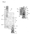
- FIG. 4 is an explanatory view showing the outline of the arrangement of the second main spindle unit 100.
- the servomotor 120 attached to the head unit 105 moves the ram shaft 110 in the direction of the W-axis via a drive system such as a ball spring.
- a ram head 130 is attached to the lower end of the ram shaft 110.
- the ram head 130 comprises a hydraulic clamp unit 140 and a gear transmission mechanism 160.
- a turning head 200 is attached to the ram head 130.
- a turning tool T 2 is attached to the turning head 200, which is fixed to the ram shaft 110 via the hydraulic clamp unit 140 of the ram head 130.
- the hydraulic clamp unit 140 has a piston 140 operated via hydraulic pressure, which supports the turning head 200 using a taper shank 205.
- FIG. 5 shows a case in which the second main spindle unit 100 is used to subject a work K 1 to a bore turning process.
- the second main spindle unit 100 can subject deep areas of the work K 1 to turning process by projecting the ram shaft 110.
- the ram shaft 110 is projected along the W-axis so as to subject deep areas of the work K 1 to a turning process efficiently.
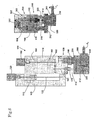
- FIG. 6 illustrates a state in which a milling head 300 is attached to the ram head 130 at the leading end of the ram shaft.
- the milling head 300 is supported by the hydraulic clamp unit 140 of the ram head 130 using a shank 305. This supporting mechanism is similar to how the turning head 200 is supported.
- the second main spindle unit 100 has a mill driving motor 150 disposed at the upper portion of the ram shaft 110, and drives the gear transmission mechanism 160 disposed on the side of the ram head 130 via the driving shaft 152.
- the gear transmission mechanism 160 comprises a pair of mesh gears 162 and 164, and drives an output shaft 166.
- a clutch 170 is disposed at the leading end of the drive shaft 166, which is connected to an input shaft 310 disposed on the side of the milling head 300.
- the milling head 300 comprises a pair of mesh gears 312 and 314 and a bevel gear 320, and drives a spindle 330 disposed in a direction orthogonal to the input shaft 310.
- a mill tool T 3 is attached to the spindle 330.
- the driving mechanism of the milling head of the present invention since the driving mechanism of the milling head of the present invention has its driving system arranged at a position offset from the axis line of the hydraulic clamp unit, the milling head can be effectively downsized.
- the driving motor of the mill tool can be disposed at the upper portion of the ram shaft, the structure thereof can be simplified.
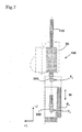
- FIG. 7 shows a case in which the ram shaft 110 equipped with the milling head 300 which is an angle head is extended so as to provide a milling process using a mill tool T 3 to a deep portion of the work K 1 .
- the present invention is applied to a gate-type machining center, but the present invention can also be applied to other types of machining centers.
- FIG. 8 illustrates an example in which the present invention is applied to a column-type machining center.
- the machining center illustrated as a whole by reference number 500 has a rotary table 520 disposed on a bed 510.
- a saddle 530 is disposed so as to be moved arbitrarily in an X-axis direction on the bed 510.
- a column 540 is disposed slidably in a Y-axis direction on the saddle 530, which is controlled to move by a servomotor 532.
- a head unit 550 On the front side of the column 540 is disposed a head unit 550 capable of sliding arbitrarily in a Z-axis direction or perpendicular direction, which is controlled to move by a servomotor 542.
- a first main spindle unit 600 is attached to the head unit 550.
- the first main spindle unit 600 has a first main spindle 610, and subjects a work on the table 520 to necessary processes.
- a second main spindle unit 700 is attached to the head unit 550.
- the second main spindle unit 700 has a ram shaft 710, and the ram shaft 710 is controlled to move along a W-axis parallel to the Z-axis by a servomotor 720.
- the functions of the first main spindle unit 600 and the second main spindle unit 700 are the same as those described in the aforementioned embodiment.
Applications Claiming Priority (1)
| Application Number | Priority Date | Filing Date | Title |
|---|---|---|---|
| JP2007019639A JP5030606B2 (ja) | 2007-01-30 | 2007-01-30 | マシニングセンタ |
Publications (1)
| Publication Number | Publication Date |
|---|---|
| EP1952937A1 true EP1952937A1 (fr) | 2008-08-06 |
Family
ID=38969966
Family Applications (1)
| Application Number | Title | Priority Date | Filing Date |
|---|---|---|---|
| EP07405312A Ceased EP1952937A1 (fr) | 2007-01-30 | 2007-10-19 | Centre d'usinage avec deux têtes de broche |
Country Status (4)
| Country | Link |
|---|---|
| US (1) | US7500297B2 (fr) |
| EP (1) | EP1952937A1 (fr) |
| JP (1) | JP5030606B2 (fr) |
| CN (1) | CN101234474A (fr) |
Cited By (13)
| Publication number | Priority date | Publication date | Assignee | Title |
|---|---|---|---|---|
| WO2011057941A1 (fr) * | 2009-11-12 | 2011-05-19 | Stama Maschinenfabrik Gmbh | Procédé et machine-outil pour l'usinage simultané de deux pièces |
| CN102814708A (zh) * | 2012-08-29 | 2012-12-12 | 宜兴市灵人机械有限公司 | 一种3c产品加工专用机 |
| CN103878424A (zh) * | 2012-12-19 | 2014-06-25 | 鸿准精密模具(昆山)有限公司 | 金属件铣削方法 |
| CN103878591A (zh) * | 2012-12-19 | 2014-06-25 | 鸿准精密模具(昆山)有限公司 | 金属件加工方法 |
| EP2745958A3 (fr) * | 2012-12-19 | 2015-01-21 | Fu Ding Electronical Technology (Jiashan) Co., Ltd. | Machine-outil avec outil de tournage et fraise |
| EP2745959A3 (fr) * | 2012-12-19 | 2015-02-11 | Fu Ding Electronical Technology (Jiashan) Co., Ltd. | Machine-outil avec outil de tournage et lame de raclage |
| EP2745960A3 (fr) * | 2012-12-19 | 2015-04-15 | Fu Ding Electronical Technology (Jiashan) Co., Ltd. | Procédé d'usinage d'un élément métallique à l'aide de tournage et broyage/raclage |
| EP2745962A3 (fr) * | 2012-12-19 | 2015-04-15 | Fu Ding Electronical Technology (Jiashan) Co., Ltd. | Procédé d'usinage d'un élément métallique à l'aide de tournage et de raclage |
| EP2745961A3 (fr) * | 2012-12-19 | 2015-04-15 | Fu Ding Electronical Technology (Jiashan) Co., Ltd. | Procédé d'usinage d'un élément métallique à l'aide de tournage et de fraisage |
| EP3045264A3 (fr) * | 2014-10-28 | 2016-08-10 | Fu Ding Electronical Technology (Jiashan) Co., Ltd. | Mécanisme de traitement et dispositif de traitement utilisant celui-ci |
| US9550257B2 (en) | 2012-12-19 | 2017-01-24 | Fu Ding Electronical Technology (Jiashan) Co., Ltd. | Method for machining metallic member using lathing and milling |
| US9718153B2 (en) | 2012-12-19 | 2017-08-01 | Fu Ding Electronical Technology (Jiashan) Co., Ltd. | Method for machining metallic member using lathing and scraping |
| EP2746881B1 (fr) * | 2012-12-19 | 2021-10-27 | Fuxiang Precision Industrial (Kunshan) Co., Ltd. | Système de commande de machine employant un outil de tournage et un dispositif de coupe |
Families Citing this family (27)
| Publication number | Priority date | Publication date | Assignee | Title |
|---|---|---|---|---|
| JP2010069554A (ja) * | 2008-09-17 | 2010-04-02 | Toshiba Mach Co Ltd | 複合工具、工作機械および加工方法 |
| WO2010064478A1 (fr) * | 2008-12-02 | 2010-06-10 | ヤマザキマザック 株式会社 | Procédé d'alésage d'une pièce par une machine-outil d'usinage à 5 axes à double boîtier et machine-outil d'usinage à 5 axes à double boîtier |
| JP2010155300A (ja) * | 2008-12-26 | 2010-07-15 | Mitsubishi Heavy Ind Ltd | 工作機械 |
| JP5433344B2 (ja) * | 2009-08-10 | 2014-03-05 | 東芝機械株式会社 | 複合工具、工作機械および加工方法 |
| WO2011050750A1 (fr) * | 2009-10-29 | 2011-05-05 | 大连科德数控有限公司 | Centre d'usinage complexe à tour vertical |
| JP5525387B2 (ja) * | 2010-08-27 | 2014-06-18 | 新日本工機株式会社 | ワーク旋削装置 |
| JP5525400B2 (ja) * | 2010-09-24 | 2014-06-18 | 新日本工機株式会社 | 立旋盤 |
| CN102452004A (zh) * | 2010-10-22 | 2012-05-16 | 大连吉润高新技术机械有限公司 | 一种多功能智能立式数控机床 |
| TWM399771U (en) * | 2010-10-29 | 2011-03-11 | Jian Xue Qin | Y-axis aligned twin spindle C-model vertical machining center with dual Z-axis function |
| FR2966756B1 (fr) * | 2010-11-02 | 2013-08-23 | Snecma | Procede d'usinage d'un carter d'un turbomoteur d'aeronef et outil de grattoir pour la mise en oeuvre du procede |
| JP5784410B2 (ja) * | 2011-08-17 | 2015-09-24 | Thk株式会社 | 五面加工機、及びこれに用いられる回転テーブル機構 |
| CN103252517B (zh) * | 2012-02-17 | 2016-08-03 | 沈阳机床股份有限公司中捷钻镗床厂 | 一种卧式铣镗床用运动分配机构 |
| CN103567459B (zh) * | 2012-07-20 | 2016-06-08 | 鸿准精密模具(昆山)有限公司 | 具有非回转曲面的工件 |
| CN103878635B (zh) * | 2012-12-19 | 2018-05-04 | 鸿准精密模具(昆山)有限公司 | 机床控制系统 |
| CN103878534B (zh) * | 2012-12-19 | 2016-05-11 | 鸿准精密模具(昆山)有限公司 | 金属件加工方法 |
| CN103878636B (zh) * | 2012-12-19 | 2018-05-04 | 鸿准精密模具(昆山)有限公司 | 机床控制系统 |
| WO2014180002A1 (fr) * | 2013-05-10 | 2014-11-13 | 宜兴市灵人机械有限公司 | Machine-outil à usage déterminé pour l'usinage d'un élément précis de petite taille de produit 3c |
| CN115958430A (zh) | 2015-02-09 | 2023-04-14 | 株式会社迪恩机床 | 五轴加工机 |
| WO2016129884A1 (fr) * | 2015-02-10 | 2016-08-18 | 두산공작기계 주식회사 | Machine-outil |
| CN104801991B (zh) * | 2015-04-28 | 2017-04-26 | 佛山市普拉迪数控科技有限公司 | 一种具有多向加工功能的数控加工中心 |
| CN105798632B (zh) * | 2016-03-28 | 2018-03-16 | 广东长盈精密技术有限公司 | 车铣加工工艺 |
| WO2017167089A1 (fr) | 2016-03-28 | 2017-10-05 | 广东长盈精密技术有限公司 | Système de tournage/fraisage et procédé de tournage/fraisage |
| KR102584750B1 (ko) * | 2016-10-12 | 2023-10-06 | 주식회사 디엔솔루션즈 | 공구 스핀들 및 이를 포함하는 공작 기계 |
| CA3058016A1 (fr) * | 2017-04-19 | 2018-10-25 | Christopher Baker | Groupe de production de plateau de table automatise modulaire |
| CN107498320A (zh) * | 2017-08-17 | 2017-12-22 | 上海诺倬力机电科技有限公司 | 数控机床加工中心 |
| CN109955331B (zh) * | 2017-12-25 | 2021-03-23 | 许俊仁 | 车削万向仿型机 |
| CN111037295B (zh) * | 2019-12-31 | 2022-03-01 | 湖北三江航天红阳机电有限公司 | 一种车铣复合加工中心 |
Citations (9)
| Publication number | Priority date | Publication date | Assignee | Title |
|---|---|---|---|---|
| EP0314824A1 (fr) * | 1987-11-03 | 1989-05-10 | Waldrich Siegen Werkzeugmaschinenbau GmbH | Fraiseuse universelle à plusieurs axes |
| JPH06126514A (ja) * | 1991-10-28 | 1994-05-10 | Nippei Toyama Corp | 工作機械 |
| DE29504342U1 (de) * | 1995-03-14 | 1995-05-18 | Paatz Viernau Gmbh | Bohrkopf |
| DE19919645A1 (de) * | 1999-04-30 | 2000-11-09 | Stama Maschinenfabrik Gmbh | Werkzeugmaschine mit Werkzeugspindel und Revolverkopf |
| US20020006764A1 (en) * | 2000-06-26 | 2002-01-17 | Loh Optikmaschinen Ag | Device for machining optical workpieces |
| DE20204365U1 (de) | 2002-03-19 | 2002-05-29 | Deckel Maho Pfronten Gmbh | Spindelkopf für eine Universal-Fräsmaschine |
| EP1452270A1 (fr) * | 2003-02-28 | 2004-09-01 | VIGEL S.p.A. | Dispositif pour usiner des supports de freins à disque pour automobiles |
| DE102004058891A1 (de) | 2004-11-30 | 2006-06-01 | Tfd Teilefertigung Dresden Gmbh | Präzisionswerkzeugmaschine mit zwei Arbeitsspindeln |
| EP1842621A1 (fr) * | 2006-04-06 | 2007-10-10 | Homag Holzbearbeitungssysteme AG | Machine d'usinage avec une unité de broche à 5 axes |
Family Cites Families (23)
| Publication number | Priority date | Publication date | Assignee | Title |
|---|---|---|---|---|
| US2887016A (en) * | 1955-12-07 | 1959-05-19 | Giddings & Lewis | Headstock for milling machines |
| DE2739087A1 (de) * | 1976-08-30 | 1978-03-09 | Komatsu Mfg Co Ltd | Werkzeugmaschine |
| JPH0321929Y2 (fr) * | 1987-12-16 | 1991-05-14 | ||
| US4949443A (en) * | 1988-06-29 | 1990-08-21 | Tatsuhiko Saruwatari | Numerically controlled lathe |
| US4949942A (en) * | 1989-11-13 | 1990-08-21 | Isao Shoda | Table exchanging device for wood working machine |
| US5075530A (en) * | 1990-07-23 | 1991-12-24 | Lee Shih Lu | Multi-head type of electro-discharging machine |
| JP3348106B2 (ja) * | 1992-05-06 | 2002-11-20 | 株式会社森精機製作所 | 門型複合加工機 |
| US5848458A (en) * | 1997-05-15 | 1998-12-15 | Northrop Grumman Corporation | Reconfigurable gantry tool |
| US5848863A (en) * | 1997-06-09 | 1998-12-15 | Liao; Bi Hu | Working machine having different working angle |
| JPH11114759A (ja) | 1997-10-07 | 1999-04-27 | Shin Nippon Koki Co Ltd | 工作機械 |
| JPH11179628A (ja) * | 1997-12-19 | 1999-07-06 | Toshiba Mach Co Ltd | Nc工作機械 |
| US5980172A (en) * | 1998-04-20 | 1999-11-09 | Shoda Iron Works, Ltd. | Double cutting spindle unit for a cutting machine |
| US6502002B2 (en) * | 1998-05-13 | 2002-12-31 | Thermwood Corporation | System and method of implementing new product designs on computer numerical control machines |
| IT1310733B1 (it) * | 1999-11-23 | 2002-02-22 | Gifam S R L | Macchina operatrice. |
| JP2001150256A (ja) | 1999-11-29 | 2001-06-05 | Olympus Optical Co Ltd | ワークの複合加工方法 |
| JP2004066430A (ja) | 2002-08-08 | 2004-03-04 | O M Ltd | 複合工作機械 |
| JP3940346B2 (ja) | 2002-10-09 | 2007-07-04 | 株式会社Mstコーポレーション | アングルヘッド |
| JP2004160584A (ja) * | 2002-11-12 | 2004-06-10 | Mori Seiki Co Ltd | 多軸加工工作機械及びテーブルユニット着脱用治具 |
| JP2005279835A (ja) * | 2004-03-29 | 2005-10-13 | Mori Seiki Hitech Co Ltd | 複合加工機および旋削加工方法 |
| JP2005334927A (ja) * | 2004-05-26 | 2005-12-08 | Yamazaki Mazak Corp | レーザ加工機における突起物除去加工装置 |
| JP4672299B2 (ja) * | 2004-07-26 | 2011-04-20 | ヤマザキマザック株式会社 | 工作機械のバランサ取付角度算出方法、及び工作機械 |
| JP2007000966A (ja) * | 2005-06-23 | 2007-01-11 | O M Ltd | 工作機械 |
| US7172375B2 (en) * | 2005-06-23 | 2007-02-06 | Mori Seiki Co., Ltd. | Machine tool |
-
2007
- 2007-01-30 JP JP2007019639A patent/JP5030606B2/ja active Active
- 2007-10-19 EP EP07405312A patent/EP1952937A1/fr not_active Ceased
- 2007-11-02 US US11/934,107 patent/US7500297B2/en active Active
- 2007-12-06 CN CN200710196939.XA patent/CN101234474A/zh active Pending
Patent Citations (9)
| Publication number | Priority date | Publication date | Assignee | Title |
|---|---|---|---|---|
| EP0314824A1 (fr) * | 1987-11-03 | 1989-05-10 | Waldrich Siegen Werkzeugmaschinenbau GmbH | Fraiseuse universelle à plusieurs axes |
| JPH06126514A (ja) * | 1991-10-28 | 1994-05-10 | Nippei Toyama Corp | 工作機械 |
| DE29504342U1 (de) * | 1995-03-14 | 1995-05-18 | Paatz Viernau Gmbh | Bohrkopf |
| DE19919645A1 (de) * | 1999-04-30 | 2000-11-09 | Stama Maschinenfabrik Gmbh | Werkzeugmaschine mit Werkzeugspindel und Revolverkopf |
| US20020006764A1 (en) * | 2000-06-26 | 2002-01-17 | Loh Optikmaschinen Ag | Device for machining optical workpieces |
| DE20204365U1 (de) | 2002-03-19 | 2002-05-29 | Deckel Maho Pfronten Gmbh | Spindelkopf für eine Universal-Fräsmaschine |
| EP1452270A1 (fr) * | 2003-02-28 | 2004-09-01 | VIGEL S.p.A. | Dispositif pour usiner des supports de freins à disque pour automobiles |
| DE102004058891A1 (de) | 2004-11-30 | 2006-06-01 | Tfd Teilefertigung Dresden Gmbh | Präzisionswerkzeugmaschine mit zwei Arbeitsspindeln |
| EP1842621A1 (fr) * | 2006-04-06 | 2007-10-10 | Homag Holzbearbeitungssysteme AG | Machine d'usinage avec une unité de broche à 5 axes |
Cited By (21)
| Publication number | Priority date | Publication date | Assignee | Title |
|---|---|---|---|---|
| WO2011057941A1 (fr) * | 2009-11-12 | 2011-05-19 | Stama Maschinenfabrik Gmbh | Procédé et machine-outil pour l'usinage simultané de deux pièces |
| CN102814708A (zh) * | 2012-08-29 | 2012-12-12 | 宜兴市灵人机械有限公司 | 一种3c产品加工专用机 |
| CN102814708B (zh) * | 2012-08-29 | 2013-08-14 | 宜兴市灵人机械有限公司 | 一种3c产品加工专用机 |
| US9381580B2 (en) | 2012-12-19 | 2016-07-05 | Fu Ding Electronical Technology (Jiashan) Co., Ltd. | Milling method for machining metallic member |
| US9550257B2 (en) | 2012-12-19 | 2017-01-24 | Fu Ding Electronical Technology (Jiashan) Co., Ltd. | Method for machining metallic member using lathing and milling |
| EP2745958A3 (fr) * | 2012-12-19 | 2015-01-21 | Fu Ding Electronical Technology (Jiashan) Co., Ltd. | Machine-outil avec outil de tournage et fraise |
| EP2745959A3 (fr) * | 2012-12-19 | 2015-02-11 | Fu Ding Electronical Technology (Jiashan) Co., Ltd. | Machine-outil avec outil de tournage et lame de raclage |
| EP2745960A3 (fr) * | 2012-12-19 | 2015-04-15 | Fu Ding Electronical Technology (Jiashan) Co., Ltd. | Procédé d'usinage d'un élément métallique à l'aide de tournage et broyage/raclage |
| EP2745962A3 (fr) * | 2012-12-19 | 2015-04-15 | Fu Ding Electronical Technology (Jiashan) Co., Ltd. | Procédé d'usinage d'un élément métallique à l'aide de tournage et de raclage |
| EP2745961A3 (fr) * | 2012-12-19 | 2015-04-15 | Fu Ding Electronical Technology (Jiashan) Co., Ltd. | Procédé d'usinage d'un élément métallique à l'aide de tournage et de fraisage |
| CN103878424A (zh) * | 2012-12-19 | 2014-06-25 | 鸿准精密模具(昆山)有限公司 | 金属件铣削方法 |
| US9409268B2 (en) | 2012-12-19 | 2016-08-09 | Fu Ding Electronical Technology (Jiashan) Co., Ltd. | Machine tool with lathe tool and milling cutter |
| EP2746881B1 (fr) * | 2012-12-19 | 2021-10-27 | Fuxiang Precision Industrial (Kunshan) Co., Ltd. | Système de commande de machine employant un outil de tournage et un dispositif de coupe |
| US9421651B2 (en) | 2012-12-19 | 2016-08-23 | Fu Ding Electronical Technology (Jiashan) Co., Ltd. | Machine tool with lathe tool and scraping cutter |
| US9527174B2 (en) | 2012-12-19 | 2016-12-27 | Fu Ding Electronical Technology (Jiashan) Co.,Ltd. | Method for machining metallic member using lathing and milling |
| CN103878424B (zh) * | 2012-12-19 | 2016-12-28 | 鸿准精密模具(昆山)有限公司 | 金属件加工方法 |
| CN103878591A (zh) * | 2012-12-19 | 2014-06-25 | 鸿准精密模具(昆山)有限公司 | 金属件加工方法 |
| US9630278B2 (en) | 2012-12-19 | 2017-04-25 | Fu Ding Electronical Technology (Jiashan) Co., Ltd. | Method for machining metallic member using lathing and scraping |
| US9718153B2 (en) | 2012-12-19 | 2017-08-01 | Fu Ding Electronical Technology (Jiashan) Co., Ltd. | Method for machining metallic member using lathing and scraping |
| US10195702B2 (en) | 2014-10-28 | 2019-02-05 | Fuxiang Precision Industrial (Kunshan) Co., Ltd | Processing mechanism and processing device using same |
| EP3045264A3 (fr) * | 2014-10-28 | 2016-08-10 | Fu Ding Electronical Technology (Jiashan) Co., Ltd. | Mécanisme de traitement et dispositif de traitement utilisant celui-ci |
Also Published As
| Publication number | Publication date |
|---|---|
| CN101234474A (zh) | 2008-08-06 |
| US20080178447A1 (en) | 2008-07-31 |
| US7500297B2 (en) | 2009-03-10 |
| JP5030606B2 (ja) | 2012-09-19 |
| JP2008183666A (ja) | 2008-08-14 |
Similar Documents
| Publication | Publication Date | Title |
|---|---|---|
| US7500297B2 (en) | Machining center | |
| JP3238662B2 (ja) | 六面連続自動加工機および該加工機を用いた加工方法 | |
| EP1046461A3 (fr) | Machine-outil universelle | |
| JP5389213B2 (ja) | マシニングセンタ | |
| CN104959631A (zh) | 一种复合加工刀塔式数控车床 | |
| JP2008207296A (ja) | 工作機械のテーブル装置 | |
| CN202447714U (zh) | 导板钻 | |
| CN201913485U (zh) | 回转式数控液压精密平口钳 | |
| CN203579210U (zh) | 重型铣镗床回转工作台 | |
| CN108381246A (zh) | 一种全铝墙板和家具的打孔设备 | |
| CN104526785A (zh) | 一种全自动木头加工机 | |
| JP5171111B2 (ja) | パレット交換装置 | |
| JP2005335026A (ja) | テイルストック付き旋盤 | |
| CN204295800U (zh) | 一种全自动木头加工机 | |
| CN103551861A (zh) | 一种数控加工中心机床 | |
| JP2014124756A (ja) | ボーリングヘッド | |
| CN203579175U (zh) | 一种数控铣、镗复合机床 | |
| US9120157B2 (en) | NC lathe and accessory | |
| CN210651124U (zh) | 一种木工车铣复合机床 | |
| CN102601430B (zh) | 自动送料双头端铣开榫锯 | |
| CN211162890U (zh) | 一种卧式钻铣光机结构 | |
| KR20220124534A (ko) | 내부를 절삭가공하기 위한 가공장치 | |
| CN204686570U (zh) | 一种双动力复合加工机床 | |
| CN110834204A (zh) | 一种双轴复合数控机床 | |
| CN213438230U (zh) | 一种定梁数控龙门镗铣床用刀具装置 |
Legal Events
| Date | Code | Title | Description |
|---|---|---|---|
| PUAI | Public reference made under article 153(3) epc to a published international application that has entered the european phase |
Free format text: ORIGINAL CODE: 0009012 |
|
| AK | Designated contracting states |
Kind code of ref document: A1 Designated state(s): AT BE BG CH CY CZ DE DK EE ES FI FR GB GR HU IE IS IT LI LT LU LV MC MT NL PL PT RO SE SI SK TR |
|
| AX | Request for extension of the european patent |
Extension state: AL BA HR MK RS |
|
| 17P | Request for examination filed |
Effective date: 20090129 |
|
| AKX | Designation fees paid |
Designated state(s): DE FR GB IT |
|
| 17Q | First examination report despatched |
Effective date: 20090513 |
|
| STAA | Information on the status of an ep patent application or granted ep patent |
Free format text: STATUS: THE APPLICATION HAS BEEN REFUSED |
|
| 18R | Application refused |
Effective date: 20100517 |