EP1936723B1 - Prozess zur herstellung einer brennstoffzelle - Google Patents
Prozess zur herstellung einer brennstoffzelle Download PDFInfo
- Publication number
- EP1936723B1 EP1936723B1 EP06810338.1A EP06810338A EP1936723B1 EP 1936723 B1 EP1936723 B1 EP 1936723B1 EP 06810338 A EP06810338 A EP 06810338A EP 1936723 B1 EP1936723 B1 EP 1936723B1
- Authority
- EP
- European Patent Office
- Prior art keywords
- support substrate
- compact
- solid electrolyte
- fuel cell
- gas channel
- Prior art date
- Legal status (The legal status is an assumption and is not a legal conclusion. Google has not performed a legal analysis and makes no representation as to the accuracy of the status listed.)
- Ceased
Links
- 239000000446 fuel Substances 0.000 title claims description 61
- 238000000034 method Methods 0.000 title claims description 33
- 230000008569 process Effects 0.000 title description 2
- 239000000758 substrate Substances 0.000 claims description 123
- 239000007784 solid electrolyte Substances 0.000 claims description 85
- 239000000463 material Substances 0.000 claims description 74
- 238000004519 manufacturing process Methods 0.000 claims description 34
- 238000010304 firing Methods 0.000 claims description 22
- 229910010272 inorganic material Inorganic materials 0.000 claims description 19
- 239000011147 inorganic material Substances 0.000 claims description 19
- 238000003475 lamination Methods 0.000 claims description 13
- 238000010030 laminating Methods 0.000 claims description 7
- 239000000843 powder Substances 0.000 claims description 4
- OKTJSMMVPCPJKN-UHFFFAOYSA-N Carbon Chemical compound [C] OKTJSMMVPCPJKN-UHFFFAOYSA-N 0.000 claims description 3
- 229910052799 carbon Inorganic materials 0.000 claims description 3
- 239000000203 mixture Substances 0.000 claims description 3
- 239000011347 resin Substances 0.000 claims description 3
- 229920005989 resin Polymers 0.000 claims description 3
- 239000007789 gas Substances 0.000 description 119
- 239000000126 substance Substances 0.000 description 12
- 239000000919 ceramic Substances 0.000 description 10
- MCMNRKCIXSYSNV-UHFFFAOYSA-N Zirconium dioxide Chemical compound O=[Zr]=O MCMNRKCIXSYSNV-UHFFFAOYSA-N 0.000 description 8
- 238000010248 power generation Methods 0.000 description 7
- 229910052751 metal Inorganic materials 0.000 description 6
- 239000002184 metal Substances 0.000 description 6
- 229910052761 rare earth metal Inorganic materials 0.000 description 6
- PXHVJJICTQNCMI-UHFFFAOYSA-N Nickel Chemical compound [Ni] PXHVJJICTQNCMI-UHFFFAOYSA-N 0.000 description 5
- 230000015572 biosynthetic process Effects 0.000 description 5
- 238000005336 cracking Methods 0.000 description 5
- 229910002076 stabilized zirconia Inorganic materials 0.000 description 5
- 239000002737 fuel gas Substances 0.000 description 4
- 229910052746 lanthanum Inorganic materials 0.000 description 4
- 239000012528 membrane Substances 0.000 description 4
- XEEYBQQBJWHFJM-UHFFFAOYSA-N Iron Chemical compound [Fe] XEEYBQQBJWHFJM-UHFFFAOYSA-N 0.000 description 3
- 229910052769 Ytterbium Inorganic materials 0.000 description 3
- QVGXLLKOCUKJST-UHFFFAOYSA-N atomic oxygen Chemical compound [O] QVGXLLKOCUKJST-UHFFFAOYSA-N 0.000 description 3
- 230000008901 benefit Effects 0.000 description 3
- 238000005520 cutting process Methods 0.000 description 3
- 238000009792 diffusion process Methods 0.000 description 3
- 230000000694 effects Effects 0.000 description 3
- 238000001125 extrusion Methods 0.000 description 3
- 239000001301 oxygen Substances 0.000 description 3
- 229910052760 oxygen Inorganic materials 0.000 description 3
- 230000002265 prevention Effects 0.000 description 3
- 229910001404 rare earth metal oxide Inorganic materials 0.000 description 3
- 230000009467 reduction Effects 0.000 description 3
- 229910052727 yttrium Inorganic materials 0.000 description 3
- 229910052692 Dysprosium Inorganic materials 0.000 description 2
- 229910052691 Erbium Inorganic materials 0.000 description 2
- 229910052688 Gadolinium Inorganic materials 0.000 description 2
- 229910052689 Holmium Inorganic materials 0.000 description 2
- 229910002321 LaFeO3 Inorganic materials 0.000 description 2
- 229910052765 Lutetium Inorganic materials 0.000 description 2
- 229910052777 Praseodymium Inorganic materials 0.000 description 2
- 229910052772 Samarium Inorganic materials 0.000 description 2
- 229910052775 Thulium Inorganic materials 0.000 description 2
- 241000276425 Xiphophorus maculatus Species 0.000 description 2
- PNEYBMLMFCGWSK-UHFFFAOYSA-N aluminium oxide Inorganic materials [O-2].[O-2].[O-2].[Al+3].[Al+3] PNEYBMLMFCGWSK-UHFFFAOYSA-N 0.000 description 2
- 230000008859 change Effects 0.000 description 2
- 230000005611 electricity Effects 0.000 description 2
- 239000007772 electrode material Substances 0.000 description 2
- LNTHITQWFMADLM-UHFFFAOYSA-N gallic acid Chemical compound OC(=O)C1=CC(O)=C(O)C(O)=C1 LNTHITQWFMADLM-UHFFFAOYSA-N 0.000 description 2
- 238000010438 heat treatment Methods 0.000 description 2
- 229910052742 iron Inorganic materials 0.000 description 2
- FZLIPJUXYLNCLC-UHFFFAOYSA-N lanthanum atom Chemical compound [La] FZLIPJUXYLNCLC-UHFFFAOYSA-N 0.000 description 2
- 230000035699 permeability Effects 0.000 description 2
- 238000007650 screen-printing Methods 0.000 description 2
- FIXNOXLJNSSSLJ-UHFFFAOYSA-N ytterbium(III) oxide Inorganic materials O=[Yb]O[Yb]=O FIXNOXLJNSSSLJ-UHFFFAOYSA-N 0.000 description 2
- RUDFQVOCFDJEEF-UHFFFAOYSA-N yttrium(III) oxide Inorganic materials [O-2].[O-2].[O-2].[Y+3].[Y+3] RUDFQVOCFDJEEF-UHFFFAOYSA-N 0.000 description 2
- 229910052684 Cerium Inorganic materials 0.000 description 1
- MYMOFIZGZYHOMD-UHFFFAOYSA-N Dioxygen Chemical compound O=O MYMOFIZGZYHOMD-UHFFFAOYSA-N 0.000 description 1
- 229910052693 Europium Inorganic materials 0.000 description 1
- UFHFLCQGNIYNRP-UHFFFAOYSA-N Hydrogen Chemical compound [H][H] UFHFLCQGNIYNRP-UHFFFAOYSA-N 0.000 description 1
- 229910002254 LaCoO3 Inorganic materials 0.000 description 1
- 229910002262 LaCrO3 Inorganic materials 0.000 description 1
- 229910002328 LaMnO3 Inorganic materials 0.000 description 1
- 229910052779 Neodymium Inorganic materials 0.000 description 1
- 239000004698 Polyethylene Substances 0.000 description 1
- 229910052771 Terbium Inorganic materials 0.000 description 1
- 239000000956 alloy Substances 0.000 description 1
- 229910045601 alloy Inorganic materials 0.000 description 1
- 229910002064 alloy oxide Inorganic materials 0.000 description 1
- 239000011230 binding agent Substances 0.000 description 1
- 239000006229 carbon black Substances 0.000 description 1
- 239000011195 cermet Substances 0.000 description 1
- NFYLSJDPENHSBT-UHFFFAOYSA-N chromium(3+);lanthanum(3+);oxygen(2-) Chemical compound [O-2].[O-2].[O-2].[Cr+3].[La+3] NFYLSJDPENHSBT-UHFFFAOYSA-N 0.000 description 1
- 238000010344 co-firing Methods 0.000 description 1
- 239000011248 coating agent Substances 0.000 description 1
- 238000000576 coating method Methods 0.000 description 1
- 229910017052 cobalt Inorganic materials 0.000 description 1
- 239000010941 cobalt Substances 0.000 description 1
- GUTLYIVDDKVIGB-UHFFFAOYSA-N cobalt atom Chemical compound [Co] GUTLYIVDDKVIGB-UHFFFAOYSA-N 0.000 description 1
- 239000002131 composite material Substances 0.000 description 1
- 239000004020 conductor Substances 0.000 description 1
- 238000010276 construction Methods 0.000 description 1
- 238000005238 degreasing Methods 0.000 description 1
- 230000001419 dependent effect Effects 0.000 description 1
- 229910001882 dioxygen Inorganic materials 0.000 description 1
- 238000007606 doctor blade method Methods 0.000 description 1
- NLQFUUYNQFMIJW-UHFFFAOYSA-N dysprosium(III) oxide Inorganic materials O=[Dy]O[Dy]=O NLQFUUYNQFMIJW-UHFFFAOYSA-N 0.000 description 1
- 238000003411 electrode reaction Methods 0.000 description 1
- 230000002708 enhancing effect Effects 0.000 description 1
- VQCBHWLJZDBHOS-UHFFFAOYSA-N erbium(III) oxide Inorganic materials O=[Er]O[Er]=O VQCBHWLJZDBHOS-UHFFFAOYSA-N 0.000 description 1
- CMIHHWBVHJVIGI-UHFFFAOYSA-N gadolinium(III) oxide Inorganic materials [O-2].[O-2].[O-2].[Gd+3].[Gd+3] CMIHHWBVHJVIGI-UHFFFAOYSA-N 0.000 description 1
- JYTUFVYWTIKZGR-UHFFFAOYSA-N holmium oxide Inorganic materials [O][Ho]O[Ho][O] JYTUFVYWTIKZGR-UHFFFAOYSA-N 0.000 description 1
- 229910052739 hydrogen Inorganic materials 0.000 description 1
- 239000001257 hydrogen Substances 0.000 description 1
- 230000006872 improvement Effects 0.000 description 1
- 239000011810 insulating material Substances 0.000 description 1
- 229910003443 lutetium oxide Inorganic materials 0.000 description 1
- 229910052748 manganese Inorganic materials 0.000 description 1
- 229910044991 metal oxide Inorganic materials 0.000 description 1
- 238000002156 mixing Methods 0.000 description 1
- 229910052759 nickel Inorganic materials 0.000 description 1
- 230000003647 oxidation Effects 0.000 description 1
- 238000007254 oxidation reaction Methods 0.000 description 1
- 239000012188 paraffin wax Substances 0.000 description 1
- 230000002093 peripheral effect Effects 0.000 description 1
- 239000012466 permeate Substances 0.000 description 1
- -1 polyethylene Polymers 0.000 description 1
- 229920000573 polyethylene Polymers 0.000 description 1
- 239000002994 raw material Substances 0.000 description 1
- 230000000630 rising effect Effects 0.000 description 1
- FKTOIHSPIPYAPE-UHFFFAOYSA-N samarium(III) oxide Inorganic materials [O-2].[O-2].[O-2].[Sm+3].[Sm+3] FKTOIHSPIPYAPE-UHFFFAOYSA-N 0.000 description 1
- 229910052706 scandium Inorganic materials 0.000 description 1
- 238000007789 sealing Methods 0.000 description 1
- 239000004065 semiconductor Substances 0.000 description 1
- 239000002904 solvent Substances 0.000 description 1
- 238000005507 spraying Methods 0.000 description 1
- 229910052717 sulfur Inorganic materials 0.000 description 1
- ZIKATJAYWZUJPY-UHFFFAOYSA-N thulium (III) oxide Inorganic materials [O-2].[O-2].[O-2].[Tm+3].[Tm+3] ZIKATJAYWZUJPY-UHFFFAOYSA-N 0.000 description 1
- 229910052723 transition metal Inorganic materials 0.000 description 1
- 150000003624 transition metals Chemical class 0.000 description 1
Images


Classifications
-
- H—ELECTRICITY
- H01—ELECTRIC ELEMENTS
- H01M—PROCESSES OR MEANS, e.g. BATTERIES, FOR THE DIRECT CONVERSION OF CHEMICAL ENERGY INTO ELECTRICAL ENERGY
- H01M4/00—Electrodes
- H01M4/86—Inert electrodes with catalytic activity, e.g. for fuel cells
- H01M4/88—Processes of manufacture
- H01M4/8878—Treatment steps after deposition of the catalytic active composition or after shaping of the electrode being free-standing body
- H01M4/8882—Heat treatment, e.g. drying, baking
- H01M4/8885—Sintering or firing
-
- H—ELECTRICITY
- H01—ELECTRIC ELEMENTS
- H01M—PROCESSES OR MEANS, e.g. BATTERIES, FOR THE DIRECT CONVERSION OF CHEMICAL ENERGY INTO ELECTRICAL ENERGY
- H01M4/00—Electrodes
- H01M4/86—Inert electrodes with catalytic activity, e.g. for fuel cells
- H01M4/8605—Porous electrodes
- H01M4/8621—Porous electrodes containing only metallic or ceramic material, e.g. made by sintering or sputtering
-
- H—ELECTRICITY
- H01—ELECTRIC ELEMENTS
- H01M—PROCESSES OR MEANS, e.g. BATTERIES, FOR THE DIRECT CONVERSION OF CHEMICAL ENERGY INTO ELECTRICAL ENERGY
- H01M4/00—Electrodes
- H01M4/86—Inert electrodes with catalytic activity, e.g. for fuel cells
- H01M4/88—Processes of manufacture
- H01M4/8803—Supports for the deposition of the catalytic active composition
-
- H—ELECTRICITY
- H01—ELECTRIC ELEMENTS
- H01M—PROCESSES OR MEANS, e.g. BATTERIES, FOR THE DIRECT CONVERSION OF CHEMICAL ENERGY INTO ELECTRICAL ENERGY
- H01M8/00—Fuel cells; Manufacture thereof
- H01M8/02—Details
- H01M8/0202—Collectors; Separators, e.g. bipolar separators; Interconnectors
- H01M8/023—Porous and characterised by the material
- H01M8/0236—Glass; Ceramics; Cermets
-
- H—ELECTRICITY
- H01—ELECTRIC ELEMENTS
- H01M—PROCESSES OR MEANS, e.g. BATTERIES, FOR THE DIRECT CONVERSION OF CHEMICAL ENERGY INTO ELECTRICAL ENERGY
- H01M8/00—Fuel cells; Manufacture thereof
- H01M8/02—Details
- H01M8/0202—Collectors; Separators, e.g. bipolar separators; Interconnectors
- H01M8/023—Porous and characterised by the material
- H01M8/0241—Composites
- H01M8/0245—Composites in the form of layered or coated products
-
- H—ELECTRICITY
- H01—ELECTRIC ELEMENTS
- H01M—PROCESSES OR MEANS, e.g. BATTERIES, FOR THE DIRECT CONVERSION OF CHEMICAL ENERGY INTO ELECTRICAL ENERGY
- H01M8/00—Fuel cells; Manufacture thereof
- H01M8/02—Details
- H01M8/0202—Collectors; Separators, e.g. bipolar separators; Interconnectors
- H01M8/0258—Collectors; Separators, e.g. bipolar separators; Interconnectors characterised by the configuration of channels, e.g. by the flow field of the reactant or coolant
- H01M8/026—Collectors; Separators, e.g. bipolar separators; Interconnectors characterised by the configuration of channels, e.g. by the flow field of the reactant or coolant characterised by grooves, e.g. their pitch or depth
-
- H—ELECTRICITY
- H01—ELECTRIC ELEMENTS
- H01M—PROCESSES OR MEANS, e.g. BATTERIES, FOR THE DIRECT CONVERSION OF CHEMICAL ENERGY INTO ELECTRICAL ENERGY
- H01M8/00—Fuel cells; Manufacture thereof
- H01M8/02—Details
- H01M8/0202—Collectors; Separators, e.g. bipolar separators; Interconnectors
- H01M8/0258—Collectors; Separators, e.g. bipolar separators; Interconnectors characterised by the configuration of channels, e.g. by the flow field of the reactant or coolant
- H01M8/0265—Collectors; Separators, e.g. bipolar separators; Interconnectors characterised by the configuration of channels, e.g. by the flow field of the reactant or coolant the reactant or coolant channels having varying cross sections
-
- H—ELECTRICITY
- H01—ELECTRIC ELEMENTS
- H01M—PROCESSES OR MEANS, e.g. BATTERIES, FOR THE DIRECT CONVERSION OF CHEMICAL ENERGY INTO ELECTRICAL ENERGY
- H01M8/00—Fuel cells; Manufacture thereof
- H01M8/02—Details
- H01M8/0271—Sealing or supporting means around electrodes, matrices or membranes
-
- H—ELECTRICITY
- H01—ELECTRIC ELEMENTS
- H01M—PROCESSES OR MEANS, e.g. BATTERIES, FOR THE DIRECT CONVERSION OF CHEMICAL ENERGY INTO ELECTRICAL ENERGY
- H01M8/00—Fuel cells; Manufacture thereof
- H01M8/10—Fuel cells with solid electrolytes
- H01M8/12—Fuel cells with solid electrolytes operating at high temperature, e.g. with stabilised ZrO2 electrolyte
- H01M8/1213—Fuel cells with solid electrolytes operating at high temperature, e.g. with stabilised ZrO2 electrolyte characterised by the electrode/electrolyte combination or the supporting material
- H01M8/1226—Fuel cells with solid electrolytes operating at high temperature, e.g. with stabilised ZrO2 electrolyte characterised by the electrode/electrolyte combination or the supporting material characterised by the supporting layer
-
- H—ELECTRICITY
- H01—ELECTRIC ELEMENTS
- H01M—PROCESSES OR MEANS, e.g. BATTERIES, FOR THE DIRECT CONVERSION OF CHEMICAL ENERGY INTO ELECTRICAL ENERGY
- H01M8/00—Fuel cells; Manufacture thereof
- H01M8/24—Grouping of fuel cells, e.g. stacking of fuel cells
- H01M8/241—Grouping of fuel cells, e.g. stacking of fuel cells with solid or matrix-supported electrolytes
- H01M8/2425—High-temperature cells with solid electrolytes
- H01M8/2432—Grouping of unit cells of planar configuration
-
- H—ELECTRICITY
- H01—ELECTRIC ELEMENTS
- H01M—PROCESSES OR MEANS, e.g. BATTERIES, FOR THE DIRECT CONVERSION OF CHEMICAL ENERGY INTO ELECTRICAL ENERGY
- H01M8/00—Fuel cells; Manufacture thereof
- H01M8/02—Details
- H01M8/0202—Collectors; Separators, e.g. bipolar separators; Interconnectors
- H01M8/023—Porous and characterised by the material
- H01M8/0232—Metals or alloys
-
- H—ELECTRICITY
- H01—ELECTRIC ELEMENTS
- H01M—PROCESSES OR MEANS, e.g. BATTERIES, FOR THE DIRECT CONVERSION OF CHEMICAL ENERGY INTO ELECTRICAL ENERGY
- H01M8/00—Fuel cells; Manufacture thereof
- H01M8/02—Details
- H01M8/0202—Collectors; Separators, e.g. bipolar separators; Interconnectors
- H01M8/023—Porous and characterised by the material
- H01M8/0234—Carbonaceous material
-
- Y—GENERAL TAGGING OF NEW TECHNOLOGICAL DEVELOPMENTS; GENERAL TAGGING OF CROSS-SECTIONAL TECHNOLOGIES SPANNING OVER SEVERAL SECTIONS OF THE IPC; TECHNICAL SUBJECTS COVERED BY FORMER USPC CROSS-REFERENCE ART COLLECTIONS [XRACs] AND DIGESTS
- Y02—TECHNOLOGIES OR APPLICATIONS FOR MITIGATION OR ADAPTATION AGAINST CLIMATE CHANGE
- Y02E—REDUCTION OF GREENHOUSE GAS [GHG] EMISSIONS, RELATED TO ENERGY GENERATION, TRANSMISSION OR DISTRIBUTION
- Y02E60/00—Enabling technologies; Technologies with a potential or indirect contribution to GHG emissions mitigation
- Y02E60/30—Hydrogen technology
- Y02E60/50—Fuel cells
-
- Y—GENERAL TAGGING OF NEW TECHNOLOGICAL DEVELOPMENTS; GENERAL TAGGING OF CROSS-SECTIONAL TECHNOLOGIES SPANNING OVER SEVERAL SECTIONS OF THE IPC; TECHNICAL SUBJECTS COVERED BY FORMER USPC CROSS-REFERENCE ART COLLECTIONS [XRACs] AND DIGESTS
- Y02—TECHNOLOGIES OR APPLICATIONS FOR MITIGATION OR ADAPTATION AGAINST CLIMATE CHANGE
- Y02P—CLIMATE CHANGE MITIGATION TECHNOLOGIES IN THE PRODUCTION OR PROCESSING OF GOODS
- Y02P70/00—Climate change mitigation technologies in the production process for final industrial or consumer products
- Y02P70/50—Manufacturing or production processes characterised by the final manufactured product
Definitions
- the present invention relates to a method for manufacturing a fuel cell.
- a fuel cell for use in a fuel cell apparatus of conventional design is manufactured by laminating, on an electrically conductive support substrate, an inner electrode, a solid electrolyte, and an outer electrode one after another.
- an interconnector In the solid electrolyte and a part of the inner electrode which is exposed from the outer electrode is disposed an interconnector so as not to make connection to the outer electrode.
- the electrically conductive support substrate has formed therein a plurality of gas channels constituting gas passages.
- Electrical connection between one fuel cell and the other fuel cell is established by connecting the electrically conductive support substrate of one fuel cell to the outer electrode of the other fuel cell via the interconnector and a current-collecting member disposed in the electrically conductive support substrate.
- the electrically conductive support substrate of a hollow flat plate-shaped or cylindrical-shaped fuel cell has customarily been manufactured by means of extrusion.
- the support substrate is prepared by the extrusion forming method. This gives rise to a problem of lack of mass productivity. That is, in the case of adopting the extrusion forming method, it is necessary to prepare support substrate compacts on an individual basis. This leads to inefficiency in manufacturing and difficulty in mass production, in consequence whereof there results a problem of rising costs.
- JP-A 2003-297387 in the production of the flat plate-shaped fuel cell apparatus, green tapes are laminated on top of each other, and then polyethylene and carbon black are print-formed in a part of the laminate in which is formed a gas channel. Subsequently, the printed substances are caused to scatter and vanish during firing thereby to form the gas channel.
- a crack tends to be generated at a corner of the gas channel. Even granted that no crack appears in the course of manufacture, there is a possibility that generation and propagation of a crack occurs due to a long-time electric power generation that will eventually cause occurrence of gas leakage through the gas channel.
- WO 2004/088783 A1 discloses a method for manufacturing a fuel cell constituted such that on a support substrate having a gas channel formed inside are laminated a first electrode, a solid electrolyte, and a second electrode one after another.
- An object of the invention is to provide a method for manufacturing a fuel cell capable of preventing occurrence of gas leakage through a gas channel and that allows production of such a fuel cell in high volume with lower costs while preventing occurrence of cracking at corners of the gas channel.
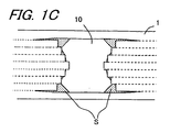
- Figs. 1A through 1C are views each showing a fuel cell in accordance with one embodiment of the invention, Fig. 1A being a transverse sectional view thereof, Fig. 1B being a vertical sectional view thereof, and Fig. 1C being an enlarged sectional view of a gas channel and the vicinities thereof.
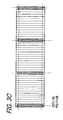
- Figs. 2A through 2F are plan views of various types of tapes that are employed in a fuel cell manufacturing method in accordance with one embodiment of the invention, Fig. 2A showing an interconnector layer tape, Fig. 2B showing a support substrate tape, Fig. 2C showing a support substrate tape having through holes, Fig. 2D showing a fuel-side electrode tape, Fig. 2E showing a solid electrolyte tape, and Fig. 2F showing an oxygen-side electrode tape.
- Figs. 3A through 3D are operation process views for explaining the fuel cell manufacturing method of one embodiment of the invention, Figs. 3A and 3B being transverse sectional views for explaining a lamination operation and Figs. 3C and 3D being views for explaining cutting positions set for a laminate, in which Fig. 3C is a plan view and Fig. 3D is a transverse sectional view.
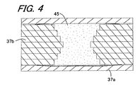
- Fig. 4 is a transverse sectional view showing a state where a space forming a gas channel is filled with a gas channel forming material.
- Figs. 5A and 5B are views each showing a state where three support substrate compacts constituting the fuel cell in accordance with another embodiment of the invention are present, Fig. 5A being a sectional view thereof and Fig. 5B being a plan view thereof.
- Figs. 6A and 6B are views each showing a state where three support substrate compacts constituting the fuel cell in accordance with still another embodiment of the invention are present, in which no solid electrolyte material 43 is formed, Fig. 6A being a plan view thereof and Fig. 6B being a sectional view thereof.
- Fig. 7 is an explanatory view showing a state where a core made of a gas channel forming material is housed in a concavity which is created as a result of laminating a plurality of support substrate tapes.
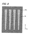
- Fig. 8 is a plan view showing the support substrate tape having formed therein through holes, the width of each of which is increased gradually from one end to the other in a direction in which a gas flows.
- Fig. 9 is a transverse sectional view showing a fuel cell manufactured by forming a solid electrolyte and an oxygen-side electrode on a support substrate which serves also as a fuel-side electrode.
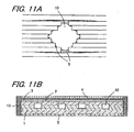
- Figs. 10A and 10B are transverse sectional views each showing a fuel cell of interconnector-less type in which a solid electrolyte is formed so as to surround a support substrate.
- Fig. 11A is a sectional view showing a state where a gas channel having a substantially circular sectional profile is formed
- Fig. 11B is a sectional view showing a state where the gas channel is formed in the vicinity of the solid electrolyte.
- a fuel cell according to the invention is, as shown in Figs. 1A through 1C , manufactured by forming a fuel-side electrode (a first electrode) 2, a solid electrolyte 3, and an oxygen-side electrode (a second electrode) 4 one after another on an upper principal surface of a support substrate 1, and also forming an interconnector layer 5 on a lower principal surface of the support substrate 1.
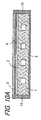
- the support substrate 1 is formed of a platy and rod-like porous element and has four gas channels 10 each having a substantially rectangular sectional profile formed inside so as to pass therethrough in a lengthwise direction.
- the porous fuel-side electrode 2 On the upper surface of the support substrate 1 are laminated the porous fuel-side electrode 2, the dense solid electrolyte 3, and the porous oxygen-side electrode 4 one after another.
- the dense interconnector layer 5 On the lower surface of the support substrate 1 is laminated the dense interconnector layer 5.
- a dense insulating gas seal layer 13 on each of opposite side surfaces of the support substrate 1 is formed a dense insulating gas seal layer 13.
- the gas seal layer 13 has its lower end connected to the interconnector layer 5 and has its upper end connected to the solid electrolyte 3.
- each of the lengthwise opposite end faces of the support substrate 1 has openings of the gas channels 10.
- the gas channel 10 has a rectangular sectional profile, and a fillet portion S is formed at a corner thereof. Thereby, the corner of the gas channel 10 is rounded off.
- a material constituting the fillet portion S is adhered not only to the four corners of the gas channel 10 but also to sharp edges of the side surface of the gas channel 10. The formation of the fillet portion S and the adhesion of the fillet portion material to the sharp edges of the side surface can be controlled in accordance with the percentage of inorganic material content in a gas channel forming material which will be described later.
- the material constituting the fillet portion S is adhered not only to the four corners of the gas channel 10 but also to the sharp edges of the side surface thereof, and as a consequence the gas channel becomes nearly circular in cross section.
- the material constituting the fillet portion S is adhered mainly to the four corners of the gas channel 10 thereby to form the fillet portions S.
- the fillet portion S is made of the material constituting the support substrate 1 and is thus porous, the material constituting the fillet portion S does not have to be an inorganic material which is electrical conductive and porous as well, so long as it lends itself to the formation of the fillet portion S at the corner of the gas channel 10.
- the fillet portion S can be made of alumina or a solid electrolyte material.
- the support substrate 1 is rectangular in cross section and is made as a platy porous conductor on the whole. In order for a fuel gas to permeate to the fuel-side electrode 2, the support substrate 1 is designed to exhibit gas permeability. Moreover, it is required that the support substrate 1 be electrically conductive to collect electricity through the interconnector layer 5. In order to satisfy such a requirement and to avoid inconveniences resulting from a co-fired operation as well, it is desirable to constitute the support substrate 1 with use of an iron-group metal component and a specific rare earth oxide.
- the thickness of the support substrate 1 is set to be greater than or equal to 1 mm in terms of supporting of a power generating portion on one hand, and is set to be smaller than or equal to 3 mm in terms of electrical conductivity between the oxygen-side electrode 4 and the interconnector layer 5 on the other hand.
- the iron-group metal component is used to impart electrical conductivity to the support substrate 1. It is possible to use any of a single iron-group metal, an iron-group metallic oxide, an alloy of iron-group metal, and an alloy oxide thereof.
- the examples of the iron-group metal include iron, nickel, and cobalt. Although any one of these materials can be used in the invention, it is preferable that Ni and/or NiO are contained as the iron-group metal component from the standpoint of inexpensiveness and stability in a fuel gas.
- the rare earth oxide is used to approximate the thermal expansion coefficient of the support substrate 1 to that of ZrO 2 containing a rare earth element constituting the solid electrolyte 2.
- an oxide containing at least one kind of rare earth element selected from the group consisting of Y, Lu, Yb, Tm, Er, Ho, Dy, Gd, Sm and Pr is used in combination with the aforementioned iron-group component.
- Such a rare earth oxide examples include Y 2 O 3 , Lu 2 O 3 , Yb 2 O 3 , Tm 2 O 3 , Er 2 O 3 , Ho 2 O 3 , Dy 2 O 3 , Gd 2 O 3 , Sm 2 O 3 , and Pr 2 O 3 .
- the use of Y 2 O 3 , Yb 2 O 3 is particularly desirable from a low cost standpoint.
- an intermediary layer may be disposed therebetween.
- a P-type semiconductor or the like may be disposed externally of the interconnector layer 5 to take out output.
- the interconnector layer 5 is made of electrically conductive ceramics. Being brought into contact with a fuel gas (hydrogen) and an oxygen-containing gas, the interconnector layer 5 needs to be designed to exhibit resistance to reduction and resistance to oxidation. Therefore, as such electrically conductive ceramics, in general, a lanthanum chromite-based perovskite-type oxide (LaCrO 3 -based oxide) is used. Moreover, in order to prevent the leakage of a fuel gas which passes through the inside of the support substrate 1 and the leakage of an oxygen-containing gas which passes through the outside of the support substrate 1, the electrically conductive ceramics needs to be dense. It is thus preferable that the electrically conductive ceramics has a relative density of, for example, 93% or above, and more particularly 95% or above.
- the interconnector layer 5 ranges in thickness from 10 to 200 ⁇ m from the standpoint of gas leakage prevention and electrical resistance.
- the fuel-side electrode 2 is provided to produce an electrode reaction, and is made of an electrically conductive porous cermet which is well known per se.
- the fuel-side electrode 2 is made of ZrO 2 in which a rare earth element is solid-solved, and Ni and/or NiO.
- ZrO 2 in which a rare earth element is solid-solved stabilized zirconia
- the content of stabilized zirconia in the fuel-side electrode 2 falls in a range of from 35 to 65% by volume, and that the content of Ni or NiO therein falls in a range of from 65 to 35% by volume. It is also preferable that the open porosity of the fuel-side electrode 2 is greater than or equal to 15%, and more particularly falls in a range of from 20 to 40%. Further, it is preferable that the thickness of the fuel-side electrode 2 falls in a range of from 1 to 30 ⁇ m from the standpoint of enhancing performance capabilities and preventing occurrence of peeling or the like trouble resulting from the difference in thermal expansion between the solid electrolyte 3 and the fuel-side electrode 2.
- the solid electrolyte 3 disposed on the fuel-side electrode 2 is made of dense ceramics which is ZrO 2 in which a rare earth element is solid-solved (usually called: stabilized zirconia) in an amount of, in general, 3 to 15 mol %.
- a rare earth element is solid-solved (usually called: stabilized zirconia) in an amount of, in general, 3 to 15 mol %.
- the examples of the rare earth element include Sc, Y, La, Ce, Pr, Nd, Pm, Sm, Eu, Gd, Tb, Dy, Ho, Er, Tm, Yb and Lu.
- the use of Y, Yb is particularly desirable from a low cost standpoint.
- the stabilized zirconia ceramics constituting the solid electrolyte 3 is dense to have a relative density (according to the Archimedes' method) of 93% or above, and more particularly 95% or above, and that its thickness falls in a range of from 10 to 100 ⁇ m.
- the solid electrolyte 3 may be made of a lanthanum gallate-based perovskite-type composite instead of the stabilized zirconia.
- the gas seal layer 13 is composed of a solid electrolyte material membrane made of a solid electrolyte material in terms of a reduction in the number of kinds of materials to be used and reliable sealing of a gas. Nevertheless, the gas seal layer 13 may be formed of any given material so long as it is a dense insulating material. For example, the gas seal layer may be formed of alumina.
- the gas seal layer 13 formed on each of the opposite side surfaces of the support substrate 1 is composed of the solid electrolyte material membrane
- a material which is slightly different in composition from the material constituting the solid electrolyte 3 can also be used. It is thus possible to use a lanthanum gallate-based solid electrolyte material.
- this region does not contribute to electric power generation, it is not necessary to use a solid electrolyte material.
- commonly-used insulating dense ceramics can also be used. It is preferable that the thickness of the gas seal layer 13 composed of the solid electrolyte material membrane is, just as is the case with the solid electrolyte 3, adjusted to be greater than or equal to 10 ⁇ m from the standpoint of gas permeation prevention.
- the oxygen-side electrode 4 is made of electrically conductive ceramics composed of a so-called ABO 3 perovskite-type oxide.
- a perovskite-type oxide a transition metal perovskite-type oxide, and more particularly at least one kind of substances selected from among an LaMnO 3 -based oxide having La in the A-site, an LaFeO 3 -based oxide, and an LaCoO 3 -based oxide are desirable.
- the use of the LaFeO 3 -based oxide is particularly desirable.
- perovskite-type oxide may be such as to contain, in addition to La, Sr or the like in the A-site, and may also be such as to contain, in addition to Fe, Co, Mn, or the like in the B-site.
- the oxygen-side electrode 4 needs to be designed to exhibit gas permeability. Therefore, the electrically conductive ceramics (perovskite-type oxide) constituting the oxygen-side electrode 4 should preferably have an open porosity of greater than or equal to 20%, and more particularly an open porosity falling in a range of from 30 to 50%. It is preferable that such an oxygen-side electrode 4 ranges in thickness from 30 to 100 ⁇ m from the standpoint of electricity collecting property. An oxygen gas, oxygen-containing air, and the like are supplied to the oxygen-side electrode 4.
- the oxygen-side electrode 4 Being made to have a high open porosity, the oxygen-side electrode 4 is liable to suffer from breakage at its end portions.
- the gas seal layer 13 formed on both sides of the support substrate 1 has its upper end portion made to protrude upwardly from the upper surface of the solid electrolyte 3 so that the oxygen-side electrode 4 can be formed between the upper end portions of the gas seal layers 13 by means of filling.
- the fuel cell having the structure thus far described can be manufactured in the following manner.
- an organic binder, a solvent, and so forth are admixed in powder of a predetermined raw material.
- the thus obtained admixture is compacted into tapes by the doctor blade method so as to form 6 varieties of tapes as shown in Figs. 2A through 2F .
- Fig. 2A shows an interconnector layer tape 35
- Fig. 2B shows a support substrate tape 37a
- Fig. 2C shows a support substrate tape 37b forming the gas channel 10
- Fig. 2D shows a fuel-side electrode tape 32
- Fig. 2E shows a solid electrolyte tape 33
- Fig. 2F shows an oxygen-side electrode tape 34.
- Each of these tapes, exclusive of the solid electrolyte tape 33 shown in Fig. 2E has formed therein a plurality of through holes in the direction of thickness of the tape, of which each has a rectangular sectional profile and extends in a lengthwise direction.
- Each of these through holes is filled with a solid electrolyte material 43 becoming a gas seal compact to constitute the gas seal layer 13 composed of the solid electrolyte material membrane.
- a plurality of additional through holes are formed in the support substrate tape 37b intended to form the gas channel 10 in the support substrate tape 37b intended to form the gas channel 10 in the support substrate tape 37b intended to form the gas channel 10 in the support substrate tape 37b intended to form the gas channel 10 in the support substrate tape 37b intended to form the gas channel 10 are formed a plurality of additional through holes, of which each has a rectangular sectional profile and extends in the lengthwise direction, to form the gas channel 10.
- Each of these additional through holes is filled with a gas channel forming material 45 prepared by mixing the inorganic material constituting the fillet portion S with a substance which is scattered at the time of firing, namely a to-be-scattered substance.
- the support substrate material is desirable in terms of compatibility with the support substrate.
- resin such as a paraffin wax and carbon are desirable.
- a through hole having a rectangular sectional profile can be created in the direction of thickness of the tape by means of stamping.
- the through hole can be filled with a paste containing the solid electrolyte material 43, as well as a paste containing the gas channel forming material 45 by means of screen printing.
- the solid electrolyte material 43 as well as the gas channel forming material 45 can be shaped into a sheet-like member and then housed in the through hole.
- the space having a rectangular sectional profile created as a result of laminating three pieces of the support substrate tapes 37b one after another, is filled with the gas channel forming material 45.
- the fuel-side electrode tape 32 shown in Fig. 2D is laminated in such a manner that the individual solid electrolyte materials 43 lying inside the through holes of the former and the latter are aligned with each other.
- the solid electrolyte tape 33 shown in Fig. 2E is laminated on the upper surface of the fuel-side electrode tape 32 in such a manner that the solid electrolyte material 43 lying inside the through hole of the oxygen-side electrode tape 34 and those lying inside the through holes of the fuel-side electrode tape 32 and the support substrate tapes 37a and 37b are aligned with each other.
- the solid electrolyte materials 43 of the individual layers are laminated on top of each other. As will be described later, by cutting the midportion of a stack of the solid electrolyte materials 43 in the direction of thickness of the laminate, it is possible to obtain three pieces of fuel cell laminates from a single laminate.
- the laminate is cut up at the positions indicated by alternate long and short dashed lines in Figs. 3C and 3D ; that is, the solid electrolyte material 43 is subjected to cutting at its midportion in the direction of thickness thereof while the lengthwise opposite ends of the solid electrolyte material 43 are cut away.
- the laminate is cut up in the lengthwise direction in such a manner as to divide the solid electrolyte material 43 lying inside the through hole of the laminate into two portions.
- the fuel cell laminates are each subjected to degreasing and firing to cause the to-be-scattered substance constituting the gas channel forming material 45 to scatter, thus forming the gas channel 10.
- the fuel cell according to the invention can be manufactured in that way.
- the cross sectional dimensions of the fuel cell are respectively 1.5 to 10 mm in thickness, and 15 to 40 mm in width, and the length of the fuel cell (the length in the direction in which the gas channel is formed) is 100 to 200 mm, for example. Note that, in Figs. 2A through 2F , Fig. 3C , and Fig. 5B , the fuel cell is illustrated as having a reduced lengthwise dimension.
- the gas channel 10 has such a sectional profile as shown in Fig. 1C in which the inner surface bears irregularities due to the conditions of the support substrate sheets to be laminated.
- This sectional profile of the gas channel 10 is a determinant factor of whether or not the fuel cell is manufactured by the sheet lamination method.
- the laminate is fired.
- the to-be-scattered substance constituting the gas channel forming material 45 is caused to scatter, and simultaneously, as indicated by a symbol S in Fig. 1C , the inorganic material is caused to spread to the four corners of the gas channel of the support substrate 1 thereby to form the fillet portions S.
- the degree of intimate contact among the tapes can be increased through the application of pressure.
- the space constituting the gas channel is so shaped that its side surfaces protrude inwardly and convexly, and as a consequence the four corners of the gas channel are each acute-angled. In this case, peeling or cracking in the support substrate tapes 37a and 37b at the acute-angled corners is prone to occur.
- the inorganic material contained in the gas channel forming material 45 is caused to spread to the four corners of the gas channel 10 under a capillary phenomenon. This makes the formation of the fillet portions S possible.
- the thick gas seal layers can be formed on the side surfaces thereof, and therefore it is possible to improve the gas sealability.
- the oxygen-side electrode 4 may also be formed in the following manner. Following the completion of co-firing of the solid electrolyte tape and the support substrate tape, the oxygen-side electrode material is applied to the tapes by means of spray coating or otherwise so that it can be print-coated onto the solid electrolyte.
- Figs. 5A and 5B show another embodiment of the invention that can be manufactured in the following manner.
- the support substrate compact 37 is formed, and, following the completion of firing, the fuel-side electrode, the solid electrolyte, and oxygen-side electrode are formed thereon.
- the solid electrolyte and so forth is formed by applying and baking the materials used for their formation onto the support substrate thus obtained.
- Figs. 6A and 6B show still another embodiment of the invention that can be manufactured in the following manner.
- the individual tapes are laminated on top of each other without forming the solid electrolyte material 43.
- the laminate is cut up at the positions indicated by alternate long and short dashed lines.
- the solid electrolyte material 43 is formed on the side surfaces of the support substrate 1 thus obtained.
- the support substrate 1 having formed thereon the solid electrolyte 3 and the interconnector 5 is immersed in a solution containing the solid electrolyte material, with the areas other than the part in which is formed the solid electrolyte material 43 kept masked, whereupon the solid electrolyte material 43 is formed on the side surfaces of the support substrate 1 through a heating treatment.
- the above embodiment description deals with the case where the through holes of the support substrate tapes 37b are filled with the gas channel forming material 45 and subsequently these support substrate tapes 37b are laminated on top of each other, it is also practicable that, as shown in Fig. 7 , the through hole is not filled with any material at the step of forming the tapes, and, following the completion of tape lamination, a core 53 made of the gas channel forming material is housed inside a concavity 51 created as a result of laminating a plurality of the support substrate tapes 37b.
- the core 53 is formed by applying an inorganic material 53b constituting the fillet portion S around a to-be-scattered substance 53a which is scattered during firing, and, after the thus obtained core 53 having a coating of the inorganic material 53b is housed inside the concavity 51, firing is carried out.
- the inorganic material 53b of the core 53 is caused to spread to the four corners thereby to form the fillet portions S.
- the sintered compact thus obtained is immersed in a solution containing the inorganic material constituting the fillet portions S. In this way, the inorganic material is adhered to the corners of the gas channel. Then, heat treatment is carried out so that the inorganic material portions can be print-coated thereto, whereby the fillet portions S are formed.
- the above embodiment description deals with the case where the interconnector layer tape 35, the support substrate tapes 37a and 37b, the fuel-side electrode tape 32, the solid electrolyte tape 33, and the oxygen-side electrode tape 34 are each laminated in the limited number
- the invention is not limited to the number of layers given in the above description.
- the formation of an intermediary layer or the like on the tapes is not deemed to be a detriment to the implementation of the invention.
- the through hole can be so shaped that its width becomes larger gradually from one end to the other in a gas flowing direction G.
- a gas can be diffused to the solid electrolyte sufficiently in the direction of the length of the cell.
- the concentration of a gas is high at the gas inlet port of the fuel cell, whereas it is low at the gas outlet port thereof. Therefore, while gas diffusion can be achieved adequately with the cross-sectional area of the gas channel 10 at its inlet port reduced to thereby increase the velocity of flow of a gas, since the concentration of a gas is low at the outlet port, it is possible to increase the area of the gas channel 10 and thereby decrease the velocity of flow of a gas. As a consequence, satisfactory gas diffusion can be achieved.
- the invention is applicable to a case where the support substrate 1 serves also as the fuel-side electrode 2, in other words, as shown in Fig. 9 , such a fuel cell as manufactured by forming, on a support substrate 11 which serves also as a fuel-side electrode, the solid electrolyte 3 and the oxygen-side electrode 4. Also in this case, it is possible to achieve the same effects as achieved in the above-described embodiment.
- Such a fuel cell can be manufactured in the same manner as in the above-described fuel cell shown in Figs. 1A through 1C except that, in the former, the fuel-side electrode material is used as the support substrate material.
- the above embodiment description pertains to the fuel cell constituted by forming, on the support substrate, the fuel-side electrode, the solid electrolyte, and the oxygen-side electrode one after another in the order named
- the invention is applicable to a fuel cell constructed by forming, on the support substrate, the oxygen-side electrode, the solid electrolyte, and the fuel-side electrode one after another in the order named. Also in this case, it is possible to achieve the same effects as achieved in the above-described embodiment. In addition, even if the fuel cell is so deigned that the support substrate serves also as the oxygen-side electrode, it is possible to achieve the same effects as achieved in the above-described embodiment.
- the invention is also applicable to the production of a so-called interconnector-less type fuel cell as shown in Figs. 10A and 10B in which the support substrate is surrounded with the solid electrolyte.
- a solid electrolyte tape is employed instead of the interconnector layer tape shown in Figs. 3A through 3D .
- the solid electrolyte 3 and the oxygen-side electrode via the fuel-side electrode are formed on the lower surface of the support substrate 1 .
- the invention is also applicable to a case where, as shown in Fig. 11A , a gas channel having a substantially circular sectional profile is formed. With the provision of the gas channel having such a configuration, it is possible to increase the strength of the support substrate.
- the invention is also applicable to a case where, as shown in Fig. 11B , the gas channel 10 is formed at a position which is closer to the solid electrolyte 3 rather than the interconnector 5. In this case, the power generation capability can be enhanced.
- the fillet portions formed at the corners of the gas channel of the support substrate by virtue of the fillet portions formed at the corners of the gas channel of the support substrate, occurrence of cracking at the corners of the gas channel can be suppressed in the course of manufacture of the fuel cell.
- the gas channel forming material composed of an inorganic material and the space corresponding to the configuration of the gas channel of the support substrate compact is filled with a to-be-scattered substance
- the to-be-scattered substance contained in the gas channel forming material is caused to scatter, and simultaneously the inorganic material is caused to congregate to the corners of the gas channel, in particular to crevices of the corners created as a result of pressurizing the support substrate compact (peeled-off portions), under a capillary phenomenon.
- the fillet portions are formed and thereby the corners of the gas channel can be rounded off. This makes it possible to prevent occurrence of cracking in the course of manufacture of the cell.
- propagation of a crack from the corners of the gas channel can be prevented.
- the support substrate compact, the first electrode compact, and the solid electrolyte at one time or by firing the support substrate compact which serves also as the first electrode and the solid electrolyte compact at one time, it is possible to expedite mass production even further which brings costs down.
- the first electrode compact and/or the solid electrolyte compact in the form of a tape it is possible to laminate, on the support substrate compact composed of a lamination of a plurality of green tapes, the tape-shaped first electrode compact and/or the tape-shaped solid electrolyte compact continuously. This helps expedite mass production.
- the support substrate is formed by laminating a plurality of green tapes containing powder of the support substrate material on top of each other and thereafter firing the laminate. Therefore, it is possible to adopt the sheet lamination method, the screen printing method, and so forth as have conventionally been in use as a method for manufacturing a ceramic substrate, and thus achieve mass production by means of automatic machinery. This makes cost reduction possible.
Landscapes
- Chemical & Material Sciences (AREA)
- Engineering & Computer Science (AREA)
- Chemical Kinetics & Catalysis (AREA)
- General Chemical & Material Sciences (AREA)
- Electrochemistry (AREA)
- Manufacturing & Machinery (AREA)
- Sustainable Development (AREA)
- Sustainable Energy (AREA)
- Life Sciences & Earth Sciences (AREA)
- Ceramic Engineering (AREA)
- Composite Materials (AREA)
- Physics & Mathematics (AREA)
- Thermal Sciences (AREA)
- Fuel Cell (AREA)
Claims (10)
- Verfahren zur Herstellung einer Brennstoffzelle, die so ausgestaltet ist, dass auf einem Trägersubstrat, in dem ein Gaskanal ausgeformt ist, eine erste Elektrode, ein fester Elektrolyt und eine zweite Elektrode aufeinanderfolgend geschichtet sind, wobei das Verfahren dadurch gekennzeichnet ist, dass ein Trägersubstrat durch einen Schritt des Brennens eines Trägersubstrat-Presskörpers gebildet wird, der durch Aufeinanderschichten einer Mehrzahl von Greentape-Bändern hergestellt wird, die jeweils ein Durchgangsloch aufweisen, das in ihrer Dickenrichtung ausgebildet ist und Pulver eines Trägersubstratmaterials enthält, wobei in dem Trägersubstrat-Presskörper ein Raum einer Gaskanalkonfiguration, der durch die Durchgangslöcher in der Mehrzahl von Greentape-Bändern gebildet ist, mit einem Material (45) zum Bilden eines Gaskanals gefüllt ist, das aus einer Mischung eines anorganischen Materials zum Ausbilden eines abgerundeten Bereichs an einer Ecke eines Gaskanals und einem Harz oder Kohlenstoff besteht, welches bzw. welcher während des Brennens abgebrannt wird.
- Verfahren zur Herstellung der Brennstoffzelle nach Anspruch 1, mit: einem Schritt der Herstellung eines Laminats, auf dem ein erster Elektroden-Presskörper und ein fester Elektrolyt-Presskörper aufeinanderfolgend auf den Trägersubstrat-Presskörper geschichtet sind, einem Schritt des Brennens des Laminats, und einem Schritt der Ausbildung der zweiten Elektrode auf dem festen Elektrolyten eines gesinterten Presskörpers.
- Verfahren zur Herstellung der Brennstoffzelle nach Anspruch 1 oder 2, wobei die erste Elektrode eine brennstoffseitige Elektrode ist und die zweite Elektrode eine sauerstoffseitige Elektrode.
- Verfahren zur Herstellung einer Brennstoffzelle, die so ausgestaltet ist, dass auf einem Trägersubstrat, in dem ein Gaskanal ausgeformt ist und welches als erste Elektrode dient, ein fester Elektrolyt und eine zweite Elektrode aufeinanderfolgend geschichtet sind, wobei das Verfahren dadurch gekennzeichnet ist, dass ein Trägersubstrat durch einen Schritt des Brennens eines Trägersubstrat-Presskörpers hergestellt wird, der durch Aufeinanderschichten einer Mehrzahl von Greentape-Bändern gebildet ist, die jeweils ein Durchgangsloch aufweisen, das in ihrer Dickenrichtung ausgebildet ist und Pulver eines Trägersubstratmaterials enthält, wobei in dem Trägersubstrat-Presskörper ein Raum einer Gaskanalkonfiguration, der durch die Durchgangslöcher in der Mehrzahl von Greentape-Bändern gebildet ist, mit einem Material (45) zum Bilden eines Gaskanals gefüllt ist, das aus einer Mischung eines anorganischen Materials zum Ausbilden eines abgerundeten Bereichs an einer Ecke eines Gaskanals und einem Harz oder Kohlenstoff besteht, welches bzw. welcher während des Brennens abgebrannt wird.
- Verfahren zur Herstellung einer Brennstoffzelle nach Anspruch 4, mit: einem Schritt des Herstellens eines Laminats, auf dem ein Festelektrolyt-Presskörper auf den Trägersubstrat-Presskörper geschichtet ist, einem Schritt des Brennens des Laminats, und einem Schritt des Bildens der zweiten Elektrode auf dem Festelektrolyten eines gesinterten Presskörpers.
- Verfahren zur Herstellung der Brennstoffzelle nach Anspruch 4 oder 5, wobei das Trägersubstrat ein Trägersubstrat ist, welches ebenfalls als brennstoffseitige Elektrode dient, und wobei die zweite Elektrode eine sauerstoffseitige Elektrode ist.
- Verfahren zur Herstellung der Brennstoffzelle nach einem der Ansprüche 1 bis 6, wobei ein Teil der Oberfläche eines Trägersubstrat-Presskörpers, der frei ist von einer Beschichtung mit einem Festelektrolyt-Presskörper, mit einem isolierenden Gasabdichtungs-Presskörper abgedeckt ist.
- Verfahren zur Herstellung der Brennstoffzelle nach einem der Ansprüche 1 bis 7, wobei das Laminat einen Festelektrolyt-Presskörper aufweist, der auf seiner einen Hauptfläche, gesehen in einer Richtung, in der die Greentape-Bänder, die den Trägersubstrat-Presskörper bilden, geschichtet sind, ausgebildet ist, und wobei das Laminat einen Verbinder-Presskörper aufweist, der auf dessen anderen Hauptfläche geformt ist, und wobei die Flächen der entgegengesetzten Seite des Trägersubstrat-Presskörpers jeweils mit einem isolierenden Gasdichtungs-Presskörper bedeckt sind, und wobei der Rand des Trägersubstrat-Presskörpers mit dem Festelektrolyt-Presskörper, dem Verbinder-Presskörper und dem isolierenden Gasdichtungs-Presskörper bedeckt ist.
- Verfahren zur Herstellung der Brennstoffzelle nach Anspruch 8, wobei ein erstes Trägersubstratband und ein zweites Trägersubstratband zu ihrer Verwendung hergerichtet werden, wobei das erste Trägersubstratband eine Mehrzahl von mit Gasabdichtungsmaterial gefüllten Durchgangslöchern aufweist, die sich in ihrer Längsrichtung erstrecken, wogegen das zweite Trägersubstratband ferner eine Mehrzahl von Durchgangslöchern aufweist, die mit einem einen Gaskanal bildenden Material gefüllt sind, und die sich in ihrer Längsrichtung erstrecken, wobei die Durchgangslöcher zwischen den benachbart nebeneinander liegenden mit Gasabdichtungsmaterial gefüllten Durchgangslöchern des ersten Trägersubstratbandes angeordnet sind, und wobei, nachdem eine Mehrzahl von den ersten Trägersubstratbändern aufeinandergeschichtet sind, eine Mehrzahl von den zweiten Trägersubstratbändern auf einer oberen Fläche davon geschichtet werden, und wobei eine Mehrzahl der ersten Trägersubstratbänder ferner auf einer oberen Flächen davon geschichtet werden, wodurch ein Trägersubstratanordnungs-Presskörper gebildet wird, und wobei der Trägersubstratanordnungs-Presskörper in seiner Längsrichtung derart aufgeschnitten wird, dass er das Gasabdichtungsmaterial, welches in dem Durchgangsloch liegt, in zwei Teile teilt, woraufhin ein Trägersubstrat-Presskörper gebildet wird, dessen sich gegenüberliegende Seitenflächen jeweils mit einem isolierenden Gasdichtungs-Presskörpers bedeckt sind.
- Verfahren zur Herstellung der Brennstoffzelle nach einem der Ansprüche 7 bis 9, wobei der isolierende Gasdichtungs-Presskörper ein Festelektrolytmaterial enthält.
Applications Claiming Priority (2)
| Application Number | Priority Date | Filing Date | Title |
|---|---|---|---|
| JP2005271858 | 2005-09-20 | ||
| PCT/JP2006/318642 WO2007034835A1 (ja) | 2005-09-20 | 2006-09-20 | 燃料電池セルおよびその製法 |
Publications (3)
| Publication Number | Publication Date |
|---|---|
| EP1936723A1 EP1936723A1 (de) | 2008-06-25 |
| EP1936723A4 EP1936723A4 (de) | 2010-12-08 |
| EP1936723B1 true EP1936723B1 (de) | 2013-06-05 |
Family
ID=37888878
Family Applications (1)
| Application Number | Title | Priority Date | Filing Date |
|---|---|---|---|
| EP06810338.1A Ceased EP1936723B1 (de) | 2005-09-20 | 2006-09-20 | Prozess zur herstellung einer brennstoffzelle |
Country Status (6)
| Country | Link |
|---|---|
| US (1) | US20100151348A1 (de) |
| EP (1) | EP1936723B1 (de) |
| JP (1) | JP4825215B2 (de) |
| CN (1) | CN101268576B (de) |
| CA (1) | CA2623302A1 (de) |
| WO (1) | WO2007034835A1 (de) |
Families Citing this family (12)
| Publication number | Priority date | Publication date | Assignee | Title |
|---|---|---|---|---|
| JP5176362B2 (ja) * | 2007-03-29 | 2013-04-03 | 大日本印刷株式会社 | 固体酸化物形燃料電池用構造体及びこれを用いた固体酸化物形燃料電池 |
| JP5167670B2 (ja) * | 2007-03-30 | 2013-03-21 | 大日本印刷株式会社 | 固体酸化物形燃料電池 |
| US8658328B2 (en) * | 2008-03-26 | 2014-02-25 | Japan Fine Ceramics Center | Stack structure for laminated solid oxide fuel cell, laminated solid oxide fuel cell and manufacturing method |
| JP5326330B2 (ja) * | 2008-04-04 | 2013-10-30 | 株式会社村田製作所 | 固体電解質形燃料電池とその製造方法 |
| JP5362605B2 (ja) * | 2010-02-05 | 2013-12-11 | 日本碍子株式会社 | 固体酸化物形燃料電池のセル |
| JP2011165379A (ja) * | 2010-02-05 | 2011-08-25 | Ngk Insulators Ltd | 固体酸化物形燃料電池セル |
| JP5987278B2 (ja) * | 2011-08-01 | 2016-09-07 | 大日本印刷株式会社 | 固体酸化物形燃料電池 |
| JP5929027B2 (ja) * | 2011-08-01 | 2016-06-01 | 大日本印刷株式会社 | 固体酸化物形燃料電池および固体酸化物形燃料電池の製造方法 |
| JP6212003B2 (ja) * | 2014-07-30 | 2017-10-11 | 株式会社ノリタケカンパニーリミテド | 円筒型sofcハーフセルグリーン体およびその焼成物である円筒型sofc |
| JP6622635B2 (ja) * | 2016-03-24 | 2019-12-18 | 京セラ株式会社 | 固体酸化物形燃料電池セルおよび燃料電池モジュールならびに燃料電池装置 |
| JP6213614B2 (ja) * | 2016-06-01 | 2017-10-18 | 大日本印刷株式会社 | 固体酸化物形燃料電池および固体酸化物形燃料電池の製造方法 |
| JP6797779B2 (ja) * | 2017-10-31 | 2020-12-09 | 株式会社東芝 | 電気化学セル及び電気化学装置 |
Family Cites Families (15)
| Publication number | Priority date | Publication date | Assignee | Title |
|---|---|---|---|---|
| JPH06283178A (ja) * | 1993-03-29 | 1994-10-07 | Nippon Telegr & Teleph Corp <Ntt> | 固体電解質型燃料電池の電解質膜製造方法 |
| DE19547700C2 (de) * | 1995-12-20 | 1998-09-17 | Forschungszentrum Juelich Gmbh | Elektrodensubstrat für eine Brennstoffzelle |
| MXPA03004079A (es) * | 2000-11-09 | 2004-10-15 | Univ Pennsylvania | El uso de combustible que contienen azufre para pilas de combustible de oxidacion directa. |
| DE10152792A1 (de) * | 2001-10-25 | 2003-05-08 | Bayer Ag | Methode zur Integration einer Gasdiffusionselektrode in einen elektrochemischen Reaktionsapparat |
| JP4113720B2 (ja) | 2002-03-29 | 2008-07-09 | Tdk株式会社 | 固体電解質燃料電池の製造方法 |
| US20030194592A1 (en) * | 2002-04-10 | 2003-10-16 | Hilliard Donald Bennett | Solid oxide electrolytic device |
| JP2004055194A (ja) * | 2002-07-17 | 2004-02-19 | Mitsubishi Materials Corp | 固体酸化物形燃料電池の電極 |
| US6893769B2 (en) * | 2002-12-18 | 2005-05-17 | Hewlett-Packard Development Company, L.P. | Fuel cell assemblies and methods of making the same |
| JP2004207088A (ja) * | 2002-12-26 | 2004-07-22 | Nissan Motor Co Ltd | ガス透過性基体及びこれを用いた固体酸化物形燃料電池 |
| JP4261927B2 (ja) | 2003-01-29 | 2009-05-13 | 京セラ株式会社 | 固体電解質形燃料電池セル及び燃料電池 |
| JP3935086B2 (ja) * | 2003-02-17 | 2007-06-20 | 京セラ株式会社 | 燃料電池セル及び燃料電池 |
| EP1453128B1 (de) * | 2003-02-28 | 2010-12-15 | Kyocera Corporation | Brennstoffzelle |
| US7838166B2 (en) * | 2003-03-31 | 2010-11-23 | Tokyo Gas Co., Ltd. | Method for fabricating solid oxide fuel cell module |
| DE10334131A1 (de) * | 2003-07-25 | 2005-02-17 | Webasto Ag | Verfahren zur Herstellung eines Brennstoffzellenstapels |
| KR101136191B1 (ko) * | 2003-09-10 | 2012-04-17 | 트르스티스 오브 보스톤 유니버시티 | 고체 산화물 연료전지 제조 방법 |
-
2006
- 2006-09-20 CN CN2006800346677A patent/CN101268576B/zh not_active Expired - Fee Related
- 2006-09-20 WO PCT/JP2006/318642 patent/WO2007034835A1/ja active Application Filing
- 2006-09-20 EP EP06810338.1A patent/EP1936723B1/de not_active Ceased
- 2006-09-20 CA CA002623302A patent/CA2623302A1/en not_active Abandoned
- 2006-09-20 US US12/067,440 patent/US20100151348A1/en not_active Abandoned
- 2006-09-20 JP JP2007536535A patent/JP4825215B2/ja not_active Expired - Fee Related
Also Published As
| Publication number | Publication date |
|---|---|
| CA2623302A1 (en) | 2007-03-29 |
| JPWO2007034835A1 (ja) | 2009-03-26 |
| WO2007034835A9 (ja) | 2008-03-20 |
| EP1936723A1 (de) | 2008-06-25 |
| US20100151348A1 (en) | 2010-06-17 |
| JP4825215B2 (ja) | 2011-11-30 |
| WO2007034835A1 (ja) | 2007-03-29 |
| EP1936723A4 (de) | 2010-12-08 |
| CN101268576B (zh) | 2011-08-17 |
| CN101268576A (zh) | 2008-09-17 |
Similar Documents
| Publication | Publication Date | Title |
|---|---|---|
| EP1936723B1 (de) | Prozess zur herstellung einer brennstoffzelle | |
| EP2851984B1 (de) | Leitfähiges element, zellenstapel, elektrochemisches modul und elektrochemische vorrichtung | |
| EP2355217B1 (de) | Brennstoffzelle, brennstoffzellenmodul, brennstoffzellenelement und verfahren zur herstellung einer brennstoffzelle | |
| AU784450B2 (en) | High performance ceramic fuel cell interconnect with integrated flowpaths and method for making same | |
| US7351487B2 (en) | Fuel cell | |
| EP2061108B1 (de) | Brennstoffbatteriezelle, brennstoffbatteriezellenstapel und brennstoffbatterie | |
| EP2495791A1 (de) | Brennstoffzelle, brennstoffzellenstapel, brennstoffzellenmodul und brennstoffzellenvorrichtung | |
| JP5922434B2 (ja) | 固体酸化物形燃料電池 | |
| AU5407901A (en) | Solid oxide fuel cell | |
| JP5105840B2 (ja) | 平板型燃料電池のインターコネクタ及びその製法、平板型燃料電池、平板型燃料電池スタック並びにその製法 | |
| JP4999305B2 (ja) | 燃料電池セル及び燃料電池 | |
| EP1528615B1 (de) | Brennstoffzelle | |
| JP2004265734A (ja) | 燃料電池セル | |
| EP1453128B1 (de) | Brennstoffzelle | |
| JP4798947B2 (ja) | 燃料電池セル及びセルスタック並びに燃料電池 | |
| JP4594035B2 (ja) | 燃料電池セル及び燃料電池 | |
| JP2017134941A (ja) | 燃料電池単セル | |
| JP5036163B2 (ja) | 燃料電池セル及びセルスタック並びに燃料電池 | |
| WO2018042476A1 (ja) | インターコネクタ、固体酸化物形燃料電池スタック、及び固体酸化物形燃料電池スタックの製造方法 | |
| JP4925574B2 (ja) | 燃料電池セル及び燃料電池 | |
| EP1484811B1 (de) | Festoxidbrennstoffzelle | |
| WO2018042477A1 (ja) | インターコネクタ、固体酸化物形燃料電池スタック、及び固体酸化物形燃料電池スタックの製造方法 | |
| JP4557578B2 (ja) | 燃料電池セル及びセルスタック並びに燃料電池 | |
| WO2018042479A1 (ja) | 固体酸化物形燃料電池用セル、固体酸化物形燃料電池スタック及び固体酸化物形燃料電池 | |
| WO2018042480A1 (ja) | 固体酸化物形燃料電池スタック及びその製造方法 |
Legal Events
| Date | Code | Title | Description |
|---|---|---|---|
| PUAI | Public reference made under article 153(3) epc to a published international application that has entered the european phase |
Free format text: ORIGINAL CODE: 0009012 |
|
| 17P | Request for examination filed |
Effective date: 20080320 |
|
| AK | Designated contracting states |
Kind code of ref document: A1 Designated state(s): DE |
|
| RBV | Designated contracting states (corrected) |
Designated state(s): DE |
|
| RBV | Designated contracting states (corrected) |
Designated state(s): DE |
|
| DAX | Request for extension of the european patent (deleted) | ||
| A4 | Supplementary search report drawn up and despatched |
Effective date: 20101105 |
|
| 17Q | First examination report despatched |
Effective date: 20101118 |
|
| GRAP | Despatch of communication of intention to grant a patent |
Free format text: ORIGINAL CODE: EPIDOSNIGR1 |
|
| GRAS | Grant fee paid |
Free format text: ORIGINAL CODE: EPIDOSNIGR3 |
|
| GRAA | (expected) grant |
Free format text: ORIGINAL CODE: 0009210 |
|
| AK | Designated contracting states |
Kind code of ref document: B1 Designated state(s): DE |
|
| REG | Reference to a national code |
Ref country code: DE Ref legal event code: R096 Ref document number: 602006036697 Country of ref document: DE Effective date: 20130801 |
|
| PLBE | No opposition filed within time limit |
Free format text: ORIGINAL CODE: 0009261 |
|
| STAA | Information on the status of an ep patent application or granted ep patent |
Free format text: STATUS: NO OPPOSITION FILED WITHIN TIME LIMIT |
|
| 26N | No opposition filed |
Effective date: 20140306 |
|
| REG | Reference to a national code |
Ref country code: DE Ref legal event code: R097 Ref document number: 602006036697 Country of ref document: DE Effective date: 20140306 |
|
| REG | Reference to a national code |
Ref country code: DE Ref legal event code: R082 Ref document number: 602006036697 Country of ref document: DE Representative=s name: VIERING, JENTSCHURA & PARTNER PATENT- UND RECH, DE Ref country code: DE Ref legal event code: R082 Ref document number: 602006036697 Country of ref document: DE Representative=s name: VIERING, JENTSCHURA & PARTNER MBB PATENT- UND , DE |
|
| PGFP | Annual fee paid to national office [announced via postgrant information from national office to epo] |
Ref country code: DE Payment date: 20150916 Year of fee payment: 10 |
|
| REG | Reference to a national code |
Ref country code: DE Ref legal event code: R119 Ref document number: 602006036697 Country of ref document: DE |
|
| PG25 | Lapsed in a contracting state [announced via postgrant information from national office to epo] |
Ref country code: DE Free format text: LAPSE BECAUSE OF NON-PAYMENT OF DUE FEES Effective date: 20170401 |