EP1933445A2 - Spule mit konzentrierter Windung und Herstellungsverfahren dafür - Google Patents
Spule mit konzentrierter Windung und Herstellungsverfahren dafür Download PDFInfo
- Publication number
- EP1933445A2 EP1933445A2 EP07023990A EP07023990A EP1933445A2 EP 1933445 A2 EP1933445 A2 EP 1933445A2 EP 07023990 A EP07023990 A EP 07023990A EP 07023990 A EP07023990 A EP 07023990A EP 1933445 A2 EP1933445 A2 EP 1933445A2
- Authority
- EP
- European Patent Office
- Prior art keywords
- wire
- coil
- bobbin
- winding
- concentrated winding
- Prior art date
- Legal status (The legal status is an assumption and is not a legal conclusion. Google has not performed a legal analysis and makes no representation as to the accuracy of the status listed.)
- Withdrawn
Links
- 238000004804 winding Methods 0.000 title claims abstract description 171
- 238000004519 manufacturing process Methods 0.000 title claims abstract description 20
- 238000003825 pressing Methods 0.000 claims abstract description 16
- 239000010410 layer Substances 0.000 description 85
- 238000000034 method Methods 0.000 description 25
- 230000007246 mechanism Effects 0.000 description 8
- 230000007423 decrease Effects 0.000 description 4
- 230000004048 modification Effects 0.000 description 3
- 238000012986 modification Methods 0.000 description 3
- 230000003746 surface roughness Effects 0.000 description 3
- 238000005520 cutting process Methods 0.000 description 2
- 230000008569 process Effects 0.000 description 2
- 241000486679 Antitype Species 0.000 description 1
- 230000004075 alteration Effects 0.000 description 1
- 230000015572 biosynthetic process Effects 0.000 description 1
- 230000008859 change Effects 0.000 description 1
- 239000011247 coating layer Substances 0.000 description 1
- 238000010276 construction Methods 0.000 description 1
- 230000003247 decreasing effect Effects 0.000 description 1
- 230000000593 degrading effect Effects 0.000 description 1
- 230000000694 effects Effects 0.000 description 1
- 239000012212 insulator Substances 0.000 description 1
- 238000010137 moulding (plastic) Methods 0.000 description 1
- 238000005498 polishing Methods 0.000 description 1
- 230000009467 reduction Effects 0.000 description 1
Images







Classifications
-
- H—ELECTRICITY
- H02—GENERATION; CONVERSION OR DISTRIBUTION OF ELECTRIC POWER
- H02K—DYNAMO-ELECTRIC MACHINES
- H02K3/00—Details of windings
- H02K3/04—Windings characterised by the conductor shape, form or construction, e.g. with bar conductors
- H02K3/18—Windings for salient poles
-
- H—ELECTRICITY
- H01—ELECTRIC ELEMENTS
- H01F—MAGNETS; INDUCTANCES; TRANSFORMERS; SELECTION OF MATERIALS FOR THEIR MAGNETIC PROPERTIES
- H01F41/00—Apparatus or processes specially adapted for manufacturing or assembling magnets, inductances or transformers; Apparatus or processes specially adapted for manufacturing materials characterised by their magnetic properties
- H01F41/02—Apparatus or processes specially adapted for manufacturing or assembling magnets, inductances or transformers; Apparatus or processes specially adapted for manufacturing materials characterised by their magnetic properties for manufacturing cores, coils, or magnets
- H01F41/04—Apparatus or processes specially adapted for manufacturing or assembling magnets, inductances or transformers; Apparatus or processes specially adapted for manufacturing materials characterised by their magnetic properties for manufacturing cores, coils, or magnets for manufacturing coils
- H01F41/06—Coil winding
- H01F41/082—Devices for guiding or positioning the winding material on the former
-
- H—ELECTRICITY
- H01—ELECTRIC ELEMENTS
- H01F—MAGNETS; INDUCTANCES; TRANSFORMERS; SELECTION OF MATERIALS FOR THEIR MAGNETIC PROPERTIES
- H01F41/00—Apparatus or processes specially adapted for manufacturing or assembling magnets, inductances or transformers; Apparatus or processes specially adapted for manufacturing materials characterised by their magnetic properties
- H01F41/02—Apparatus or processes specially adapted for manufacturing or assembling magnets, inductances or transformers; Apparatus or processes specially adapted for manufacturing materials characterised by their magnetic properties for manufacturing cores, coils, or magnets
- H01F41/04—Apparatus or processes specially adapted for manufacturing or assembling magnets, inductances or transformers; Apparatus or processes specially adapted for manufacturing materials characterised by their magnetic properties for manufacturing cores, coils, or magnets for manufacturing coils
- H01F41/06—Coil winding
- H01F41/082—Devices for guiding or positioning the winding material on the former
- H01F41/086—Devices for guiding or positioning the winding material on the former in a special configuration on the former, e.g. orthocyclic coils or open mesh coils
-
- H—ELECTRICITY
- H02—GENERATION; CONVERSION OR DISTRIBUTION OF ELECTRIC POWER
- H02K—DYNAMO-ELECTRIC MACHINES
- H02K15/00—Processes or apparatus specially adapted for manufacturing, assembling, maintaining or repairing of dynamo-electric machines
- H02K15/04—Processes or apparatus specially adapted for manufacturing, assembling, maintaining or repairing of dynamo-electric machines of windings prior to their mounting into the machines
- H02K15/043—Processes or apparatus specially adapted for manufacturing, assembling, maintaining or repairing of dynamo-electric machines of windings prior to their mounting into the machines winding flat conductive wires or sheets
- H02K15/0431—Concentrated windings
-
- H—ELECTRICITY
- H01—ELECTRIC ELEMENTS
- H01F—MAGNETS; INDUCTANCES; TRANSFORMERS; SELECTION OF MATERIALS FOR THEIR MAGNETIC PROPERTIES
- H01F27/00—Details of transformers or inductances, in general
- H01F27/28—Coils; Windings; Conductive connections
- H01F27/2823—Wires
-
- H—ELECTRICITY
- H01—ELECTRIC ELEMENTS
- H01F—MAGNETS; INDUCTANCES; TRANSFORMERS; SELECTION OF MATERIALS FOR THEIR MAGNETIC PROPERTIES
- H01F27/00—Details of transformers or inductances, in general
- H01F27/28—Coils; Windings; Conductive connections
- H01F27/2823—Wires
- H01F27/2828—Construction of conductive connections, of leads
-
- Y—GENERAL TAGGING OF NEW TECHNOLOGICAL DEVELOPMENTS; GENERAL TAGGING OF CROSS-SECTIONAL TECHNOLOGIES SPANNING OVER SEVERAL SECTIONS OF THE IPC; TECHNICAL SUBJECTS COVERED BY FORMER USPC CROSS-REFERENCE ART COLLECTIONS [XRACs] AND DIGESTS
- Y10—TECHNICAL SUBJECTS COVERED BY FORMER USPC
- Y10T—TECHNICAL SUBJECTS COVERED BY FORMER US CLASSIFICATION
- Y10T29/00—Metal working
- Y10T29/49—Method of mechanical manufacture
- Y10T29/49002—Electrical device making
- Y10T29/4902—Electromagnet, transformer or inductor
- Y10T29/49071—Electromagnet, transformer or inductor by winding or coiling
Definitions
- the present invention relates to a concentrated winding coil for use in an electric motor for example. Furthermore, this invention relates to a method of manufacturing the concentrated winding coils.
- a stator comprising a core and a winding wire, used for various kinds of electric motors
- winding density of the wire has been required to increase in order to pursue high efficiency of the electric motor.
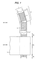
- Fig. 1 is a schematic illustration showing top and side views of a conventional concentrated winding coil disposed in a core.
- Fig. 1 shows a positional relationship between a coiled bobbin 10 and a core 5, wherein a wire 2 is wound around a bobbin 1 in the core 5.
- the circumferential length of the bobbin's outer flange 1-b is longer than that of the bobbin's inner flange 1-c.
- the coiled bobbin 10 includes a coil slot section 10a located inside the core 5 and a coil end section 10b located outside the core 5.
- the coil slot is a rectangle shape having a long side on the coil slot section 10a side and a short side on the coil end section 10b side as shown in the cross sectional view of Fig. 2 .
- Fig. 2 is a schematic illustration showing a top view and a cross sectional view cutting along A-A line in the top view of an example of a conventional bobbin 1 used for a concentrated winding coil.
- the outer flange 1-b and the inner flange 1-c are configured respectively on each side of the bobbin body 1-a, around which a wire 2 is wound, so as to prevent the wire 2 from removing from the bobbin body 1-a.
- an R (round) portion is provided on each of the four corners of the bobbin body 1-a. The radius of the R portion is usually determined according to the flexibility of the wire 2 and the strength of coating layer (insulator) of the wire 2.
- FIG. 3 is a model drawing for explaining the winding problem.
- side A and side C are of the coil slot section
- side B and side D are of the coil end section
- a terminal wire is pulled out in the direction of side D.
- each side is drawn with the same length.
- the winding method is: a wire is wound around the bobbin by the rotation of the bobbin with regard to a wire nozzle (not shown).
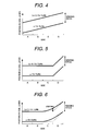
- Fig. 4 is a drawing for explaining a relationship between a wire position in a coil layer and a side of the bobbin.
- Fig. 4 shows the trajectory of the wire in the n-th turn and the (n+1)-th turn ("n" is a natural number) on each side of the bobbin when guiding of the wire 2 in the coil axis direction (expressed as "wire traverse") with a constant rate is provided in synchronization with a rotation angle of the bobbin.
- the wire 2 of the (n+1)-th turn is wound in close contact with the previous turn (n-th turn) not to have a gap therebetween in order to increase the winding density.
- FIG. 5 is a drawing for explaining another relationship between a wire position in a coil layer and a side of the bobbin. As shown in Fig. 5 , this is a method in which wire traverse is not executed between side A and side C but is executed only on side D, thereby increasing the slot-fill rate in the coil slot section on side A and side C.
- Fig. 6 is an explanatory drawing that shows an actual winding state with occurrence of a wire drifting.
- a wire drifting occurs only on side C, or in the range from side C to side B, or from side C to side A.
- JP-A-2003-244906 a method has been proposed in which a pair of wire guides called “former” are disposed on the outer circumference of the winding bobbin, and a wire is put through the guides and is wound around the winding bobbin.
- the former is approximated to the bobbin's flanges and is moved from the inner flange to the outer flange with winding the wire, thereby increasing the accuracy of positioning the wire on the winding bobbin.
- Fig. 7 is a schematic illustration showing cross sectional views at a slot portion of another example of a conventional bobbin and a concentrated winding coil wound on the bobbin in which a process of wire winding until the third coil layer is illustrated.
- a bobbin 1 has grooves that correspond to the wire pitch on the bobbin body 1-a.
- a wire guide method shown in Fig. 5
- the grooves of the bobbin body 1-a prevent the drifting that disturbs the wire alignment as shown in Fig. 6 .
- drifting of the wire is inhibited by the grooves of the bobbin body 1-a, and on the second and after coil layers, the wound wire on the previous coil layer achieves the same function as grooves.
- the present invention is originated to solve the above problems. It is an object of the present invention to provide a concentrated winding coil having a high slot-fill rate, which prevents the occurrence of disturbance in wire alignment and contributes to increasing the efficiency of the electric motor and reducing the size of an electric motor. Furthermore, it is another object of the present invention to provide a method of manufacturing said concentrated winding coil without increasing bobbin die costs.
- the present invention provides a concentrated winding coil having a high slot-fill rate, which can prevent the occurrence of disturbance in wire alignment and contribute to increasing the efficiency of the electric motor and reducing the size of an electric motor. Furthermore, the present invention provides a method of manufacturing said concentrated winding coil without increasing bobbin die manufacture costs.
- FIGs. 8(a) to 8(g) description will be provided about winding the first coil layer adjacent to the bobbin body by a winding method according to the present invention.
- One of essential points of the present invention is the positional relationship among a wire guiding/holding member, a wire and a bobbin during the winding; therefore, description of other parts will be omitted.
- Figs. 8(a) to 8(g) are schematic illustrations showing top views of a concentrated winding coil for explaining a winding method according to the present invention.
- Fig. 8(a) shows a bobbin 1 before a wire is wound around.
- the bobbin 1 comprises: a bobbin body 1-a on which a wire 2 is wound and which has no guide grooves; an outer flange 1-b which prevents a wire 2 from removing and is located on the outer circumference when the bobbin 1 is disposed in the core 5; and an inner flange 1-c which also prevents a wire 2 from removing and is located on the inner circumference when the bobbin 1 is disposed in the core 5.
- Fig. 8(b) shows a state in which a start-of-winding wire 2-a is positioned on the bobbin 1.
- winding is started while a wire is adjacent to the outer flange 1-b and is located on the left side of the bobbin body 1-a; however, winding can be started from other positions depending on the location of the terminal wire or on the coil winding direction.
- the position of the wire guiding/holding member of front side 3-a will be explained when the start-of-winding wire 2-a is positioned on the bobbin 1.
- the wire guiding/holding portion of front side 3-a is disposed on a winding spindle around which the bobbin 1 rotates, thereby the wire guiding/holding member of front side 3-a rotates along with the bobbin 1. That is, it is not necessary to position the mechanism on the outer circumference portion separate from the winding spindle. As a result, it is possible to inhibit the decrease in rotation rate of the winding spindle; and the mechanical structure allows the wire guiding/holding member of front side 3-a to press and hold the wire 2 while the winding spindle rotates (described later in detail).
- the wire guiding/holding member of front side 3-a comprises an end portion 3-a1 which faces the bobbin body 1-a, and a wire contact portion 3-a2 which guides a wire 2 when winding is executed.
- a surface of the wire contact portion 3-a2 comes in contact with a wire 2 while the wire is being wound and also comes in contact with the wire 2 in order to press the wire 2 (to adjust a wire alignment) after the wire 2 has reached the bobbin body 1-a. For this reason, it is desirable that the surface roughness of the wire contact portion 3-a2 be small by means of finish such as polishing.
- the distance between the end portion 3-a1 of the wire guiding/holding member of front side 3-a and the bobbin body 1-a has to be determined so that the wire 2 is prevented from entering the space and also the end portion 3-a1 is not in contact with the bobbin body 1-a.
- the distance between the end portion 3-a1 of the wire guiding/holding member of front side 3-a and the bobbin body 1-a can be set within a range of 0.1d and 0.5d to satisfy the above-mentioned conditions.
- the wire contact portion 3-a2 of the wire guiding/holding portion of front side 3-a is positioned at a distance within a range of 1.1d and 2d to the outer flange 1-b when a wire 2 does not exist between the wire contact portion 3-a2 and the outer flange 1-b, or to the most recently wound wire when a wire 2 exists and winding progresses. By setting the distance at that value, it is easy to guide the wire 2 when the wire is wound.
- Fig. 8(c) shows a state in which the winding progresses for a prescribed angle rotation from the state in Fig. 8(b) .
- the position of the wire contact portion 3-a2 of the wire guiding/holding member of front side 3-a has a clearance with regard to the diameter [d] of the wire 2; therefore, it is possible to wind a wire without interference when the wire 2 is dropped onto the bobbin body 1-a.
- Fig. 8(d) shows a state in which the wire is pressed (is adjusted) toward the outer flange 1-b by the wire contact portion 3-a2.
- the wire contact portion 3-a2 of the wire guiding/holding member of front side 3-a comes in contact with the wire 2 and presses the wire 2 toward the outer flange 1-b by a pressing mechanism, not shown, thereby making the wire 2 come in contact with the outer flange 1-b, and ensuring the wire alignment inside the bobbin 1.
- An optimal value for a pressing force should be selected according to the conditions, such as a diameter of a wire, flexibility of a wire, and wire tension while the wire is wound.
- Fig. 8(e) shows a state in which the winding further progresses when compared to the state shown in Fig. 8(d) and the wire contact portion 3-a2 of the wire guiding/holding member of front side 3-a is released from the wire 2 before the following turn of wire 2 is wound around.
- the position of the wire guiding/holding member of front side 3-a will be explained.
- the distance between the end portion 3-a1 of the wire guiding/holding member of front side 3-a and the bobbin body 1-a has to be determined so that the wire 2 is prevented from entering the space and also the end portion 3-a1 is not in contact with the bobbin body 1-a.
- the distance between the end portion 3-a1 of the wire guiding/holding member of front side 3-a and the bobbin body 1-a can be set within a range of 0.1d and 0.5d to satisfy the above-mentioned conditions.
- the wire contact portion 3-a2 of the wire guiding/holding member of front side 3-a is positioned at a distance within a range of 1.1d and 2d to the most recently wound wire. By changing the distance to that value, it is easy to guide the wire 2 when the wire is further wound.
- Fig. 8(f) shows a state in which the winding further progresses for a prescribed angle rotation from the state in Fig. 8(e) .
- the position of the wire contact portion 3-a2 of the wire guiding/holding member of front side 3-a includes a clearance to the wire 2 to be wound with regard to the diameter [d] of the wire 2; therefore, it is possible to wind a wire without interference when the wire 2 is dropped onto the bobbin body 1-a.
- Fig. 8(g) shows a state in which the wire is pressed (is adjusted) toward the outer flange 1-b by the wire contact portion 3-a2.
- the wire contact portion 3-a2 of the wire guiding/holding member of front side 3-a comes in contact with the wire 2 and presses the wire toward the outer flange 1-b by a pressing mechanism, not shown, thereby making the wire 2 come in contact with the most recently wound wire 2, and ensuring the wire alignment inside the bobbin 1.
- An optimal value for the pressing force should be selected according to the conditions, such as a diameter of a wire, flexibility of a wire, and wire tension while the wire is wound.
- Fig. 9 is a schematic illustration showing top and side views of a concentrated winding coil according to the present invention, of which state is that winding of the first coil layer progresses proximately before the last turn of the first coil layer is dropped on the bobbin body 1-a.
- the wire guiding/holding member of front side 3-a is retracted from a passage of the wire 2, and the last turn of the wire 2 of the first coil layer is positioned between the most recently wound wire 2 and the inner flange 1-c.
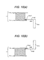
- Figs. 10(a) and 10(b) are schematic illustrations showing a top view of a coil with the first coil layer winding and that of the coil with the second coil layer winding respectively, for explaining a winding method according to the present invention.
- the method of the second coil layer winding is almost the same as that of the first coil layer winding described by referring to Figs. 8(a) to 8(g) .
- the difference is: as shown in Fig. 10(b) , a wire guiding/holding member of rear side 3-b is used, which is anteroposteriorly symmetrical with respect to the wire guiding/holding member of front side 3-a used for the first coil layer winding; and a direction of forming a coil layer is reverse, from the inner flange 1-c toward the outer flange 1-b.
- Fig. 11 is a schematic illustration showing top and side views of a concentrated winding coil according to the present invention, of which state is that winding of the second coil layer progresses proximately before the last turn of the second coil layer is dropped on the first coil layer toward the bobbin body 1-a.
- the wire guiding/holding member of rear side 3-b is retracted from the passage of the wire 2, and the last turn of the second coil layer is positioned between the most recently wound wire 2 and the outer flange 1-b.
- the wire 2 can be reached the first coil layer by pressing the wire 2 toward the bobbin body 1-a (toward the first coil layer) by means of an end portion 3-b1 of the wire guiding/holding member of rear side 3-b, as shown in Fig. 10(b) .
- the method of winding an m-th coil layer is as follows ("m" is a natural number): to wind a wire for an odd-number-th coil layer, the wire guiding/holding member of front side 3-a is used in the same manner as the first coil layer and the winding of the odd-number coil layer progresses from the outer flange 1-b toward the inner flange 1-c; and to wind a wire for an even-number-th coil layer, the wire guiding/holding member of rear side 3-b is used in the same manner as the second coil layer and the winding of the even-number coil layer progresses from the inner flange 1-c toward the outer flange 1-b.
- the disturbance in wire alignment is prone to occur in a layer shift section where the wire is shifted from an m-th coil layer to an (m+1)-th coil layer.
- the layer shift section is located only on the coil end side of the coil. The situation can be easily achieved by the winding method of the present invention because a wire on the coil slot side is guided and held during the winding by the wire guiding/holding members in the pressing mechanism according to the present invention.
- the alignment winding of a coil is not sufficiently controlled; accordingly, a length of the bobbin body in the coil axis direction is often set to be enough longer than a prescribed length of the coil layer in the same direction. In that case, when a good alignment winding is executed, a number of turns in the coil layer becomes one turn more; and when a poor alignment winding is executed, the winding on upper coil layer becomes unsteady. These situations degrade the reliability of the coils and inhibit the increase in a slot-fill rate.
- the wire guiding/holding member of front side 3-a and the wire guiding/holding member of rear side 3-b which are a pair are located only one side of the coil slot section; however, according to the degree of disturbance in wire alignment caused depending on flexibility of the wire or winding tension, by disposing another pair of wire guiding/holding members on the opposite side of the coil slot section, it is possible to further increase the effects of preventing the disturbance in wire alignment.
- Fig. 12 is a schematic illustration showing cross sectional views at a slot portion of a bobbin and of a concentrated winding coil wound on the bobbin according to a first embodiment of the present invention, in which a progress of wire winding until the third coil layer is illustrated.
- the bobbin body 1-a has no grooves, it is possible to prevent the increase in production cost resulting from groove formation, and the design capability increases because it is easy to change design conditions, such as a diameter of a wire, shape of a wire, shape of a bobbin, and so on.
- wires of the second coil layer and the third coil layer are located just right on the wires of the first coil layer.
- This winding configuration cannot be achieved by a conventional winding method, but is possible by the winding method according to the present invention.
- the winding configuration as shown in Fig. 7 can be easily manufactured by the winding method of the present invention without using a grooved bobbin.
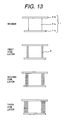
- Fig. 13 is a schematic illustration showing cross sectional views at a slot portion of a bobbin and of a concentrated winding coil wound on the bobbin according to a second embodiment of the present invention, in which a progress of wire winding until the third coil layer is illustrated.
- the wire 2 to be used is a rectangular (quadrate) wire.
- the rectangular wire is often used for an electric motor that requires a high slot-fill rate.
- By using a rectangular wire it is possible to significantly eliminate clearance that generates between coil layers of round wire and between turns of round wire.
- the conventional bobbin as shown in Fig.
- the winding method according to the present invention must be needed in order to ensure the winding alignment of the rectangular wire 2 without providing guide grooves on the bobbin body 1-a.
- Fig. 14 is a schematic illustration showing cross sectional views at a slot portion of a concentrated winding coil wound on a bobbin according to a third embodiment of the present invention, in which a progress of wire winding until the fourth coil layer is illustrated.
- the concentrated winding coil in this embodiment has the coil layer in which the number of turns differs for each coil layer.
- the bobbin has almost the same bobbin body 1-a as those shown in Figs. 12 and 13 , which has no grooves. Therefore, an explanatory drawing is omitted.
- the concentrated winding coil of this embodiment is intended to increase a slot-fill rate by decreasing a clearance between adjacent coils disposed in the core as shown in a top view of Fig. 1 . Specifically, the number of turns close to the outer flange 1-b in the coil is increased.
- the winding is executed as follows: the maximum number of turns that can fit the length of the bobbin body 1-a in the coil axis direction (the distance between the inner flange 1-c and the outer flange 1-b) are wound as the first coil layer and the second coil layer, e.g.; a turned-back position is changed in the third coil layer; and a coil layer from which the winding is started is changed in the fourth coil layer.
- This process is made possible only by the winding method according to the present invention in which a wire 2 is guided and held after the winding.
- Fig. 15 is a schematic illustration showing a perspective view of a coil end section of a concentrated winding coil wound on a bobbin according to a fourth embodiment of the present invention. As shown in Fig.15 , a start-of-winding wire, an end-of-winding wire, and terminal wire latch portions can be seen.
- the wire has to be led once to a start-of-winding half part (an opposite half part to the end-of-winding half part) on the coil end side in order to suppress slack and drift, and then has to be returned to the end-of-winding half part and be latched at the terminal wire latch position for the end-of-winding wire.
- a leading portion of the end-of-winding wire to the terminal wire latch portion must be positioned in the start-of-winding half part on the coil end viewed from the coil end.
- the present invention it is possible to prevent the wire from becoming slack and drift by directly holding the wire 2 with the wire guiding/holding member while handling for the terminal wire is executed.
- the end-of-winding wire 2-b directly to the terminal wire latch portion for the end-of-winding wire disposed in the end-of-winding half part on the coil end side viewed from the coil end, as shown in Fig. 15 .
- the leading portion of the end-of-winding wire to the terminal wire latch portion can be also positioned in the end-of-winding half part on the coil end side viewed from the coil end.
- the concentrated winding coil according to the present invention can shift all turns and all coil layers only on the coil end side, therefore maintaining a wire alignment condition of the coil, especially in the slot section inserted into a stator core. Furthermore, in the coil winding method of the present invention, a wire guiding/holding mechanism is disposed in the vicinity of a winding bobbin, and the wire guiding/holding mechanism stands ready at a position, which has a space with regard to the width of the wire, to guide the position of the wire before the wire is wound around the bobbin, and the wire guiding/holding mechanism then applies a pressing force onto the wire after the wire has been wound around.
- the wire guiding/holding member can position a wire inside the bobbin, thereby preventing the disturbance in alignment of the coil wire and enabling highly accurate winding.
- inside the bobbin means a space around the bobbin body and between the inner flange and the outer one.
Landscapes
- Engineering & Computer Science (AREA)
- Power Engineering (AREA)
- Manufacturing & Machinery (AREA)
- Manufacture Of Motors, Generators (AREA)
- Insulation, Fastening Of Motor, Generator Windings (AREA)
- Coil Winding Methods And Apparatuses (AREA)
Applications Claiming Priority (1)
| Application Number | Priority Date | Filing Date | Title |
|---|---|---|---|
| JP2006333942A JP2008148470A (ja) | 2006-12-12 | 2006-12-12 | 集中巻コイルおよび集中巻きコイルの製造方法 |
Publications (2)
| Publication Number | Publication Date |
|---|---|
| EP1933445A2 true EP1933445A2 (de) | 2008-06-18 |
| EP1933445A3 EP1933445A3 (de) | 2015-01-14 |
Family
ID=39193584
Family Applications (1)
| Application Number | Title | Priority Date | Filing Date |
|---|---|---|---|
| EP07023990.0A Withdrawn EP1933445A3 (de) | 2006-12-12 | 2007-12-11 | Spule mit konzentrierter Windung und Herstellungsverfahren dafür |
Country Status (4)
| Country | Link |
|---|---|
| US (2) | US8093779B2 (de) |
| EP (1) | EP1933445A3 (de) |
| JP (1) | JP2008148470A (de) |
| CN (2) | CN102306985B (de) |
Families Citing this family (41)
| Publication number | Priority date | Publication date | Assignee | Title |
|---|---|---|---|---|
| JP2008109829A (ja) * | 2006-10-27 | 2008-05-08 | Toyota Motor Corp | 回転電機の固定子構造及びその製造方法 |
| JP4582164B2 (ja) * | 2008-03-12 | 2010-11-17 | トヨタ自動車株式会社 | ステータ組付方法 |
| JP5233752B2 (ja) * | 2009-03-04 | 2013-07-10 | トヨタ自動車株式会社 | カセットコイル製造方法 |
| AT508080B1 (de) * | 2009-03-16 | 2012-08-15 | Egston System Electronics Eggenburg Gmbh | Verfahren zum herstellen einer spule |
| US7694909B1 (en) * | 2009-06-05 | 2010-04-13 | Remy Technologies, L.L.C. | Method of winding a flexible core |
| JP5636710B2 (ja) * | 2010-03-23 | 2014-12-10 | 日産自動車株式会社 | 回転電機のインシュレータ及びステータ巻線構造の製造方法 |
| JP5610887B2 (ja) * | 2010-07-16 | 2014-10-22 | 株式会社ベステック | 分割コア式ワークの巻線機及び巻線方法 |
| JP2012230972A (ja) | 2011-04-25 | 2012-11-22 | Sumida Corporation | コイル部品、圧粉インダクタおよびコイル部品の巻回方法 |
| WO2013157291A1 (ja) * | 2012-04-16 | 2013-10-24 | 三菱電機株式会社 | 回転電機の電機子及びそのインシュレータ及びコイル巻回装置 |
| US9343930B2 (en) | 2012-05-25 | 2016-05-17 | Baldor Electric Company | Segmented stator assembly |
| CN104137392B (zh) * | 2012-06-21 | 2017-09-22 | 三菱电机株式会社 | 旋转电机 |
| KR20140003674A (ko) * | 2012-06-22 | 2014-01-10 | 엘지이노텍 주식회사 | 모터 |
| DE102013022430B4 (de) | 2012-12-19 | 2025-02-06 | Tdk Corporation | Gleichtaktfilter |
| KR101468821B1 (ko) * | 2012-12-19 | 2014-12-03 | 티디케이가부시기가이샤 | 커먼 모드 필터 |
| US10256079B2 (en) | 2013-02-08 | 2019-04-09 | Applied Materials, Inc. | Semiconductor processing systems having multiple plasma configurations |
| USD709029S1 (en) | 2013-03-11 | 2014-07-15 | Regal Beloit America, Inc. | Electrical coil |
| US9230735B2 (en) | 2013-03-11 | 2016-01-05 | Regal Beloit America, Inc. | Electrical coil forming apparatus and methods of assembling electrical coils |
| US20140271097A1 (en) | 2013-03-15 | 2014-09-18 | Applied Materials, Inc. | Processing systems and methods for halide scavenging |
| US10177633B2 (en) | 2014-12-23 | 2019-01-08 | Abb Schweiz Ag | Multiphase fractional slot concentrated winding machine with end mounted detachable or integrated multiphase series converter circuit |
| DE102015104794A1 (de) * | 2015-03-27 | 2016-09-29 | Epcos Ag | Induktives Bauelement sowie Verfahren zur Herstellung eines induktiven Bauelements |
| EP3079242A1 (de) * | 2015-04-10 | 2016-10-12 | Siemens Aktiengesellschaft | Herstellungsverfahren einer wicklung um einen ausspringenden pol für eine synchronmaschine |
| DE202015005009U1 (de) | 2015-07-17 | 2015-08-28 | Zoltán Szöcs | Elektromotor |
| TW201707351A (zh) * | 2015-08-13 | 2017-02-16 | 建準電機工業股份有限公司 | 線圈繞組及其繞線套 |
| CN108352748B (zh) * | 2015-11-26 | 2020-02-07 | 日立汽车系统工程株式会社 | 电动机 |
| JP2017216801A (ja) * | 2016-05-31 | 2017-12-07 | 三菱電機株式会社 | コイル巻線装置及びコイル巻線方法 |
| JP6477622B2 (ja) * | 2016-07-15 | 2019-03-06 | 株式会社村田製作所 | コイル部品 |
| US10965198B2 (en) * | 2017-04-13 | 2021-03-30 | Panasonic Intellectual Property Management Co., Ltd. | Coil and motor using same |
| CN107731487A (zh) * | 2017-10-31 | 2018-02-23 | 昆山玛冀电子有限公司 | 一种用于电感生产的线圈的生产工艺 |
| DE102017221836A1 (de) * | 2017-12-04 | 2019-06-06 | Mahle International Gmbh | Elektrische Maschine, insbesondere für ein Fahrzeug |
| CN108831737B (zh) * | 2018-07-02 | 2024-01-19 | 河南森源电气股份有限公司 | 一种互感器绕线定位工装 |
| DE102018130504B4 (de) * | 2018-11-30 | 2023-11-23 | Borgwarner Ludwigsburg Gmbh | Primärspulenkörper für eine Zündspule und Zündspule mit einem solchen Primärspulenkörper |
| JP6591031B1 (ja) * | 2018-12-06 | 2019-10-16 | 三菱電機株式会社 | コイル装置 |
| CN110164682B (zh) * | 2019-04-17 | 2021-12-31 | 惠州学院 | 一种绕线装置的绕线方法 |
| JP2021048688A (ja) * | 2019-09-18 | 2021-03-25 | 日本電産トーソク株式会社 | モータ、電動ポンプ |
| CN112421908A (zh) * | 2020-10-27 | 2021-02-26 | 智新科技股份有限公司 | 高槽满率无骨架直线电机线圈的绕线装置及绕线方法 |
| WO2022107607A1 (ja) * | 2020-11-19 | 2022-05-27 | 株式会社多賀製作所 | 巻線方法及び巻線装置 |
| DE102020131417A1 (de) * | 2020-11-26 | 2022-06-02 | Nidec Motors & Actuators (Germany) Gmbh | Stator mit Drahtführung aufweisendem Isolator |
| DE102020131418A1 (de) * | 2020-11-26 | 2022-06-02 | Nidec Motors & Actuators (Germany) Gmbh | Stator mit Drahtführung aufweisendem Isolator |
| CN112489988B (zh) * | 2020-11-30 | 2022-11-01 | 保定天威集团特变电气有限公司 | 一种变压器连续式线圈制造方法、结构及变压器 |
| CN112489987B (zh) * | 2020-11-30 | 2022-09-02 | 保定天威集团特变电气有限公司 | 一种匹配调压匝数线圈制造方法、结构及变压器 |
| CN117277710A (zh) * | 2022-06-14 | 2023-12-22 | 上海舞肌科技有限公司 | 一种制造小尺寸线圈组件的绕线装置、绕线方法及小尺寸方形线圈组件 |
Citations (1)
| Publication number | Priority date | Publication date | Assignee | Title |
|---|---|---|---|---|
| JP2003244906A (ja) | 2001-12-13 | 2003-08-29 | Asmo Co Ltd | 回転電機製造方法及び回転電機 |
Family Cites Families (26)
| Publication number | Priority date | Publication date | Assignee | Title |
|---|---|---|---|---|
| US1504005A (en) * | 1922-06-01 | 1924-08-05 | Gen Electric | Coil-winding machine |
| US2930014A (en) * | 1954-12-24 | 1960-03-22 | Philips Corp | Polygonal electric coil |
| DE1181816B (de) * | 1963-01-02 | 1964-11-19 | Licentia Gmbh | Wickelvorrichtung zum axialen Aneinander-pressen der Draehte einer Roehrenwicklung |
| JPS6054419A (ja) * | 1983-09-02 | 1985-03-28 | Aichi Electric Mfg Co Ltd | 変圧器鉄心の製造方法 |
| JPS6197908A (ja) * | 1984-10-19 | 1986-05-16 | Jeol Ltd | コイル巻回方法 |
| JPS61254049A (ja) * | 1985-05-03 | 1986-11-11 | Nippon Denso Co Ltd | コイルの巻線装置 |
| JPS63222412A (ja) * | 1987-03-11 | 1988-09-16 | Mitsubishi Electric Corp | 巻線装置 |
| US4794361A (en) * | 1988-03-10 | 1988-12-27 | General Motors Corporation | Coil winding method for maximum utilization of winding envelope |
| US5174013A (en) * | 1988-06-16 | 1992-12-29 | Nippondenso Co., Ltd. | Winding apparatus and method which deforms the wire during winding |
| JP2953833B2 (ja) * | 1991-10-23 | 1999-09-27 | 北村機電株式会社 | 変圧器用巻線装置 |
| US5209414A (en) * | 1991-10-30 | 1993-05-11 | Dana Corporation | Apparatus for precisely winding a coil of wire |
| JP3715029B2 (ja) * | 1996-05-13 | 2005-11-09 | 株式会社ダイヘン | 変圧器コイルの巻回方法 |
| JP3515280B2 (ja) * | 1996-05-27 | 2004-04-05 | 株式会社三協精機製作所 | 回転電機の固定子の製造方法 |
| JPH1118331A (ja) * | 1997-06-30 | 1999-01-22 | Matsushita Electric Ind Co Ltd | モータの固定子 |
| JP3613994B2 (ja) * | 1998-02-12 | 2005-01-26 | トヨタ自動車株式会社 | 平角線コイル製造装置および平角線コイル製造方法 |
| JP2000083338A (ja) * | 1998-09-04 | 2000-03-21 | Mitsubishi Electric Corp | 車両用交流発電機の回転子 |
| JP3572209B2 (ja) | 1998-11-30 | 2004-09-29 | 株式会社東芝 | コイルの巻回方法 |
| JP3700444B2 (ja) * | 1999-02-05 | 2005-09-28 | トヨタ自動車株式会社 | コイル形成装置 |
| JP2001118505A (ja) * | 1999-10-20 | 2001-04-27 | Sony Corp | コイル巻線機及び偏向コイルの製造方法 |
| JP3498129B2 (ja) * | 2001-05-24 | 2004-02-16 | 三菱電機株式会社 | 回転電機 |
| JP3623471B2 (ja) * | 2001-09-03 | 2005-02-23 | 本田技研工業株式会社 | ステータ |
| JP3980402B2 (ja) * | 2002-05-13 | 2007-09-26 | 本田技研工業株式会社 | 回転電機 |
| WO2004038893A1 (ja) * | 2002-10-22 | 2004-05-06 | Mitsubishi Denki Kabushiki Kaisha | 回転電機の回転子 |
| JP3903922B2 (ja) * | 2003-01-27 | 2007-04-11 | 株式会社デンソー | 回転電機の集中巻きステータコイル |
| US7026739B2 (en) * | 2003-05-23 | 2006-04-11 | Honda Motor Co., Ltd | Stator and insulating bobbin and a manufacturing method of the stator |
| JP2005057931A (ja) * | 2003-08-06 | 2005-03-03 | Honda Motor Co Ltd | ステータ |
-
2006
- 2006-12-12 JP JP2006333942A patent/JP2008148470A/ja active Pending
-
2007
- 2007-12-06 CN CN201110265415.8A patent/CN102306985B/zh active Active
- 2007-12-06 CN CN2007101969455A patent/CN101202477B/zh active Active
- 2007-12-11 EP EP07023990.0A patent/EP1933445A3/de not_active Withdrawn
- 2007-12-12 US US11/954,305 patent/US8093779B2/en active Active
-
2011
- 2011-11-30 US US13/307,210 patent/US20120066897A1/en not_active Abandoned
Patent Citations (1)
| Publication number | Priority date | Publication date | Assignee | Title |
|---|---|---|---|---|
| JP2003244906A (ja) | 2001-12-13 | 2003-08-29 | Asmo Co Ltd | 回転電機製造方法及び回転電機 |
Also Published As
| Publication number | Publication date |
|---|---|
| US20120066897A1 (en) | 2012-03-22 |
| EP1933445A3 (de) | 2015-01-14 |
| CN101202477B (zh) | 2011-11-16 |
| CN101202477A (zh) | 2008-06-18 |
| CN102306985B (zh) | 2014-02-26 |
| US8093779B2 (en) | 2012-01-10 |
| CN102306985A (zh) | 2012-01-04 |
| US20080136286A1 (en) | 2008-06-12 |
| JP2008148470A (ja) | 2008-06-26 |
Similar Documents
| Publication | Publication Date | Title |
|---|---|---|
| EP1933445A2 (de) | Spule mit konzentrierter Windung und Herstellungsverfahren dafür | |
| US6975056B2 (en) | Stator | |
| JP4347219B2 (ja) | 回転電機の回転子 | |
| JP4402976B2 (ja) | ステータコア用インシュレータ及びステータコアへの巻線方法 | |
| US7872559B2 (en) | Winding method and coil unit | |
| US7166949B2 (en) | Stator and insulating bobbin and a manufacturing method of the stator | |
| EP1966808B1 (de) | Wickelverfahren und spuleneinheit | |
| WO2007055210A1 (ja) | モータコア部品及びモータ部品 | |
| WO2011111682A1 (ja) | 回転電機のステータ、ステータの製造方法、及びステータにおけるコイル製造方法 | |
| US20010015393A1 (en) | Winding apparatus | |
| JP4271495B2 (ja) | ステータ | |
| JP2011229285A (ja) | 回転電機のステータの製造方法及び回転電機のステータ | |
| TWI581282B (zh) | 線圈之捲繞方法及變壓器 | |
| US9608489B2 (en) | Rotating electrical machine armature | |
| JP7136111B2 (ja) | コイルの製造方法、コイルの製造装置、コイルおよびモータ | |
| JP2010067790A (ja) | エッジワイズコイルおよびその製造装置 | |
| JP7776998B2 (ja) | 変成器 | |
| KR100657187B1 (ko) | 광 케이블 | |
| WO2018047839A1 (ja) | 回転電機のステータ、および、その製造方法 | |
| JP6253709B2 (ja) | 回転電機の回転子 | |
| KR102741752B1 (ko) | 축방향 자속모터의 고정자용 보빈 및 평각 코일 권취방법 | |
| JP2000260650A (ja) | コイルの製造方法及びその巻線装置 | |
| EP4044408A1 (de) | Motorankerwicklungsstruktur und verfahren zum drahtwickeln eines motorankers | |
| CN111525760A (zh) | 电机绕组线圈的绕制工艺和电机绕组线圈 |
Legal Events
| Date | Code | Title | Description |
|---|---|---|---|
| PUAI | Public reference made under article 153(3) epc to a published international application that has entered the european phase |
Free format text: ORIGINAL CODE: 0009012 |
|
| AK | Designated contracting states |
Kind code of ref document: A2 Designated state(s): AT BE BG CH CY CZ DE DK EE ES FI FR GB GR HU IE IS IT LI LT LU LV MC MT NL PL PT RO SE SI SK TR |
|
| AX | Request for extension of the european patent |
Extension state: AL BA HR MK RS |
|
| PUAL | Search report despatched |
Free format text: ORIGINAL CODE: 0009013 |
|
| AK | Designated contracting states |
Kind code of ref document: A3 Designated state(s): AT BE BG CH CY CZ DE DK EE ES FI FR GB GR HU IE IS IT LI LT LU LV MC MT NL PL PT RO SE SI SK TR |
|
| AX | Request for extension of the european patent |
Extension state: AL BA HR MK RS |
|
| RIC1 | Information provided on ipc code assigned before grant |
Ipc: H02K 3/46 20060101AFI20141208BHEP Ipc: H02K 15/04 20060101ALI20141208BHEP Ipc: H01F 41/06 20060101ALI20141208BHEP Ipc: H02K 3/18 20060101ALI20141208BHEP Ipc: H02K 27/28 20060101ALI20141208BHEP Ipc: H02K 15/095 20060101ALI20141208BHEP |
|
| AKY | No designation fees paid | ||
| AXX | Extension fees paid |
Extension state: AL Extension state: RS Extension state: HR Extension state: MK Extension state: BA |
|
| STAA | Information on the status of an ep patent application or granted ep patent |
Free format text: STATUS: THE APPLICATION IS DEEMED TO BE WITHDRAWN |
|
| 18D | Application deemed to be withdrawn |
Effective date: 20150701 |