EP1966808B1 - Wickelverfahren und spuleneinheit - Google Patents
Wickelverfahren und spuleneinheit Download PDFInfo
- Publication number
- EP1966808B1 EP1966808B1 EP06832482.1A EP06832482A EP1966808B1 EP 1966808 B1 EP1966808 B1 EP 1966808B1 EP 06832482 A EP06832482 A EP 06832482A EP 1966808 B1 EP1966808 B1 EP 1966808B1
- Authority
- EP
- European Patent Office
- Prior art keywords
- wires
- winding
- coil
- bobbin
- pair
- Prior art date
- Legal status (The legal status is an assumption and is not a legal conclusion. Google has not performed a legal analysis and makes no representation as to the accuracy of the status listed.)
- Active
Links
Images






Classifications
-
- H—ELECTRICITY
- H01—ELECTRIC ELEMENTS
- H01F—MAGNETS; INDUCTANCES; TRANSFORMERS; SELECTION OF MATERIALS FOR THEIR MAGNETIC PROPERTIES
- H01F27/00—Details of transformers or inductances, in general
- H01F27/28—Coils; Windings; Conductive connections
- H01F27/2823—Wires
-
- B—PERFORMING OPERATIONS; TRANSPORTING
- B65—CONVEYING; PACKING; STORING; HANDLING THIN OR FILAMENTARY MATERIAL
- B65H—HANDLING THIN OR FILAMENTARY MATERIAL, e.g. SHEETS, WEBS, CABLES
- B65H54/00—Winding, coiling, or depositing filamentary material
- B65H54/02—Winding and traversing material on to reels, bobbins, tubes, or like package cores or formers
- B65H54/10—Winding and traversing material on to reels, bobbins, tubes, or like package cores or formers for making packages of specified shapes or on specified types of bobbins, tubes, cores, or formers
-
- H—ELECTRICITY
- H01—ELECTRIC ELEMENTS
- H01F—MAGNETS; INDUCTANCES; TRANSFORMERS; SELECTION OF MATERIALS FOR THEIR MAGNETIC PROPERTIES
- H01F41/00—Apparatus or processes specially adapted for manufacturing or assembling magnets, inductances or transformers; Apparatus or processes specially adapted for manufacturing materials characterised by their magnetic properties
- H01F41/02—Apparatus or processes specially adapted for manufacturing or assembling magnets, inductances or transformers; Apparatus or processes specially adapted for manufacturing materials characterised by their magnetic properties for manufacturing cores, coils, or magnets
- H01F41/04—Apparatus or processes specially adapted for manufacturing or assembling magnets, inductances or transformers; Apparatus or processes specially adapted for manufacturing materials characterised by their magnetic properties for manufacturing cores, coils, or magnets for manufacturing coils
- H01F41/06—Coil winding
- H01F41/082—Devices for guiding or positioning the winding material on the former
Definitions
- the present invention relates to a winding method of regularly winding wires on a bobbin, and a coil unit manufactured by the method.
- the wires can be wound on the bobbin in either multilayer or parallel winding manner.
- this publication has no particular disclosure about how to wind wires to make a resultant coil compact.
- a raised portion of the wound wires is likely to be generated near an end of the bobbin. This would result from inclination and floating of the wires at a row shift part and a layer shift part in regularly winding, namely, in a winding turn-back position.
- the regularly concentrated winding coil is likely to disorder the arrangement of the wires in the winding turn-back position, which is one of factors causing enlargement of a coil outer size, leading to obstruction of miniaturization of the concentrated winding coil.
- US 2005/115628 A upon which the precharacterising portions of appended claims 1 and 2 are based, describes a coil-winding method for forming a coil unit including the steps of winding first and second wires substantially parallel to each other simultaneously around a first layer position of a core to form a first turn, winding the first and second wires simultaneously to form a second turn while the second wire is disposed directly around the core, the first wire of the second turn adjacent to the first turn being disposed between the first and second wires of the first turn in the first layer so as to form a second layer, and winding the first and second wires simultaneously to form a third turn while the second wire is disposed directly around the core, the first wire of the third turn being disposed in the second layer and wound between the second wire of the first turn and the second wire of the second turn in the first layer.
- EP 1 699 060 A relevant under Article 54(3) EPC only, describes a multilayer coil which winds "n" wire rods ("n" is an integer number of two or more) in line around a winding core having a cross section of a polygonal shape.
- An intersection portion is formed on a face where feeding of the winding core is made by feeding the wire rods by an amount of "n" wire rods during a period when the wire rods are wound by one round around the winding core, so that the wire rods in a lower layer and an upper layer intersect therein.
- a twist portion is formed at an end of at least one face out of the faces where the feeding is made, wherein two wire rods out of "n" wire rods are twisted to replace an arrangement of the wire rods.
- the present invention has been made in view of the above circumstances and has an object to provide a method of regularly winding two wires, capable of preventing the generation of a raised portion of the wires in a winding turn-back position, thereby achieving a compact coil, and a coil manufactured by the winding method.
- the present invention provides a winding method as defined in appended claim 1.
- the wires are wound to advance obliquely together for the lane change corresponding to 0.5 wire (i.e. a half wire diameter) on one surface side of the pair of parallel surfaces of the four outer surfaces of the bobbin and the lane change corresponding to 1.5 wires (i.e. three and a half wire diameters) on the other surface side of the parallel surfaces.
- This method can provide less inclination of the wires as compared with for instance the lane change corresponding to 2 wires on one of the outer surfaces of the bobbin, with a consequent result that intersection of layered wires in turn-back positions of winding can be reduced.
- the present invention does not cause one of the two wires to be left uncoiled in the turn-back position where the winding is completed.
- the winding method is used to manufacture a rectangular coil unit including a coil having a rectangular section.
- the winding method is used to manufacture a trapezoidal coil unit including a coil having a trapezoidal section.
- the present invention provides a coil unit as defined in appended claim 2.
- the wires are wound to advance obliquely together for the lane change corresponding to 0.5 wire (i.e. a half wire diameter) on one surface side of the pair of parallel surfaces of the four outer surfaces of the bobbin and the lane change corresponding to 1.5 wires (i.e. three and a half wire diameters) on the other surface side of the parallel surfaces.
- the coil of the present invention can include less inclination of the wires as compared with for instance the lane change corresponding to 2 wires on one of the outer surfaces of the bobbin, with a consequent result that intersection of layered wires in turn-back positions of winding can be reduced.
- the present invention does not cause one of the two wires to be left uncoiled in the turn-back position where the winding is completed.
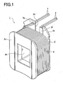
- Fig. 1 is a perspective view of a rectangular coil unit 1 in the present embodiment.
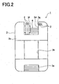
- Fig. 2 is a back view of the rectangular coil unit 1.
- Fig. 3 is a front view of the rectangular coil unit 1 from which a first flange is removed for convenience of explanation.
- the rectangular coil unit 1 in the present embodiment is manufactured in such a manner that a pair of two wires 2 is simultaneously regularly wound on four outer surfaces of a bobbin 3 having a rectangular section.
- a plurality of the rectangular coil units 1 will be mounted in a plurality of teeth formed on the inner periphery of a stator core, thus constituting a stator.
- This stator is further assembled with a rotor, producing a motor.
- the bobbin 3 includes a core tube 3a of a rectangular section, a first flange 3b and a second flange 3c formed at both axial ends of the core tube 3a.
- the bobbin 3 is made of a synthetic resin such as PPS (polyphenylene sulfide) to have an insulating property.
- the first flange 3b provided on a rear side has a distinctive shape as compared with the second flange 3c provided on a front side having a nearly normal rectangular shape.
- the first flange 3b includes upper and lower cutout portions 3d and 3e, an insulating wall 3f protruding from one of side surfaces of the upper cutout portion 3d in Fig.
- the core tube 3a is hollow, providing a center hole 3h. A clearance is formed between the insulating wall 3f and a lower surface of the upper cutout portion 3d as shown in Fig. 2 .
- two wires 2 are simultaneously regularly wound, forming a coil 4 having a hollow rectangular shape. Both end portions of each of two wires 2 are partly engaged with the insulating wall 3f and the stopper groove 3g.
- a relatively thick wire 2 is used to achieve a small-sized high-power motor.
- the wire 2 is made of a copper wire coated with an enamel insulating film.
- two wires 2 are guided onto the core tube 3a inside the first flange 3b through the clearance between the insulating wall 3f and the lower surface of the cutout portion 3d. Those two wires 2 are sequentially wound in a row on the core tube 3a in a direction advancing from the first flange 3b to the second flange 3c, forming a first layer. Then, the wires 2 are turned (folded) back along the second flange 3c and sequentially wound in a row on the first layer in a direction opposite to that for the first layer from the second flange 3c to the first flange 3b, forming a second layer.
- the two wires 2 are wound regularly and reciprocally in opposite directions along the axis of the core tube 3a as above, forming the coil 4 with a plurality of rows and a plurality of layers of wires. After winding, the end portions of the two wires 2 are engaged in the stopper groove 3g.
- the rectangular coil unit 1 including the coil 4 formed in the above manner to have a rectangular section is thus manufactured.
- the wiring method in the present embodiment has special features in a method of winding two wires.
- Fig. 4 is a side view of the coil 4 on the bobbin 3.
- Fig. 5 is a back view of the coil 4 on the bobbin.
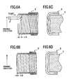
- Figs. 6A to 6D are views seen from direction indicated by arrows A, B, C, and D in Fig. 4 .
- Fig. 7 is a pattern diagram of the arrangement of the coil 4 on the bobbin 3. It is to be noted that the numbers to the wires 2 in Fig. 7 are merely given to facilitate the explanation of the wire arrangement and thus do not match to those in Figs. 6A to 6D . In the present embodiment, as shown in Figs.
- two wires 2 are wound in such a manner as to advance obliquely together for a lane change corresponding to 0.5 wire (i.e. a half wire diameter) on a lower surface side of the core tube 3a of the bobbin 3 having four outer surfaces including a pair of upper and lower parallel surfaces and to advance obliquely together for a lane change corresponding to 1.5 wires (i.e. one and a half wire diameters) on an upper surface side thereof (hereinafter, this winding method is referred to as "1.5-0.5 change").
- 1.5-0.5 change 1.5-0.5 change
- two wires 2 start to be wound from an upper side and along the first flange 3b to a left side, and then vertically downward to a lower side. Successively, the wires 2 advance obliquely together for the 0.5-wire lane change on the lower side, as indicated by number “1” in Fig. 6B , and then vertically upward on a right side to the upper side. As indicated by numbers “1” and “2” in Fig. 6A , on the upper side, the wires 2 advance obliquely together for the 1.5-wire lane change and vertically downward again on the left side to the lower side.
- the above lane changes are repeated as in the above manner on the upper side and the lower side respectively.
- the first layer of the coil 4 is thus formed (the first layer has 6 turns as indicated by numbers “1" to "6" in Figs. 6A and 6B .)
- the wires 2 are turned (folded) back at an opposite position from the winding start position.
- the 0.5-wire lane change is performed in the direction opposite to that for the first layer as shown in Fig. 6B .
- the 1.5-wire lane change is performed in the direction opposite to that the first layer as shown in Fig. 6A .
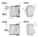
- Figs. 8A to 8D are views seen from the directions indicated by arrows A, B, C, and D in Fig. 4 .
- Fig. 9 is a pattern diagram of the arrangement of the coil 4 on the bobbin 3. It is to be noted that the numbers to the wires 2 in Fig. 9 are merely given to facilitate the explanation of the wire arrangement and thus do not match to those in Figs. 8A to 8D .
- two wires 2 are wound in such a manner as to traverse together straight for a lane change corresponding to 0 wire (i.e.
- this winding method causes the wires 2 to intersect and overlap in three layers in the winding turn-back positions as a shaded area in Fig. 8A , generating a raised portion as shown by a dot-dashed circular line S1 in Fig. 8C .
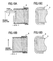
- Figs. 10A to 10D are views seen from the directions indicated by arrows A, B, C, and D in Fig. 4 .
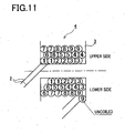
- Fig. 11 is a pattern diagram of the arrangement of the coil 4 on the bobbin 3. It is to be noted that the numbers to the wires 2 in Fig. 11 are merely given to facilitate the explanation of the wire arrangement and thus do not match to those in Figs. 10A to 10D .
- two wires 2 are wound in such a manner as to advance obliquely together for a lane change corresponding to 1 wire (i.e.
- this winding method is referred to as "1-1 change").
- the lane changes corresponding to a total of two wire diameters are performed on the upper and lower sides of the bobbin 3.
- this method when the winding is completed at the end of the bobbin 3, as shown in Fig. 11 , one of the wires 2 is left uncoiled in that winding end position corresponding to the winding turn-back position in Fig. 11 .
- the two wires 2 are wound to advance obliquely together for the 0.5-wire lane change on the lower surface side of the core tube 3a of the bobbin 3 having the four outer surfaces including the pair of upper and lower surfaces and for the 1.5-wire lane change on the upper surface side.
- the winding method using the "2-0 change" whereby the 2-wire lane change is performed on only the upper side of the bobbin 3 as shown in Figs.
- the winding method in the present embodiment can provide less inclination of the wires 2, with a consequent result that intersection of layered wires of the coil 4 in the vicinity of each flange 3b, 3c of the bobbin 3, that is, in the winding turn-back positions can be reduced.
- the winding method in the present embodiment can present one wire to be left uncoiled in the winding end position located in the vicinity of seach flange 3b, 3c of the bobbin 3 where the winding is completed. Accordingly, in simultaneously regularly winding two wires 2 for manufacturing the rectangular coil unit 1, it is possible to prevent the generation of a raised portion in the winding turn-back positions. This makes it possible to form the coil 4 compact without enlarging the outer size of the coil 4.
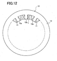
- this rectangular coil unit 1 may be mounted in each of teeth 12a of a stator core 12 in such a manner that trapezoidal coil units 11 and rectangular coil units 1 are alternately arranged to constitute a stator 13.
- the generation of a raised portion in the winding turn-back positions can be restrained, thus making compact the coil 4 of the rectangular coil unit 1.
- a predetermined distance can be ensured between the coil 4 of the rectangular coil unit 1 and the coil 4 of the trapezoidal coil unit 11 adjacent thereto. It is therefore possible to increase a space factor in assembly, ensure the insulation between the adjacently arranged coil units 1 and 11, and thus enhance performance of a motor using the above stator 13.
- the rectangular coil unit 1 manufactured according to the winding method in the present embodiment is configured so that two wires 2 are simultaneously regularly wound on the bobbin 3.
- the eddy-current loss of the rectangular coil unit 1 can therefore be reduced, which contributes to making the motor high-powered.
- the productivity of the rectangular coil units 1 can also be increased.
- Fig. 14 is a side view of a trapezoidal coil unit 11 in the present embodiment.
- Fig. 15 is a front view of the trapezoidal coil unit 11 seen from a direction indicated by arrow D in Fig. 14 .
- the trapezoidal coil unit 11 in the present embodiment is manufactured in such a manner that two wires 2 are simultaneously regularly wound on four outer surfaces of a bobbin 3 having a rectangular section, whereby forming a wound coil 4 having a trapezoidal section.
- This trapezoidal coil unit 11 will be mounted in each of teeth 12a of a stator core 12 so that the trapezoidal coil units 11 and the rectangular coil units 1 are arranged alternately as shown in Figs. 12 and 13 to constitute a stator 13.
- the bobbin 3 has substantially the same structure as the bobbin 3 in the first embodiment except that the bobbin 3 in this embodiment has a second flange 3c smaller than a first flange 3b.
- the method of winding two wires 2 is implemented in the same manner as the winding method in the first embodiment.
- Figs. 16A, 16B to Figs. 21A, 21B show the process of winding the wires 2 on the bobbin 3, in which circled numbers represent the order of turns of the wires 2.
- Figs. 16A to 21A show a lead side of the bobbin 3, namely, a view of the bobbin 3 (the upper side thereof) seen from a direction indicated by arrow A in Fig. 14 .
- Figs. 16B to 21B show an opposite side of the bobbin 3 to the lead side, namely, a view of the bobbin 3 (the lower side thereof) seen from a direction indicated by arrow B in Fig. 14 .
- two wires 2 are also regularly wound in such a manner as to advance obliquely together for a lane change corresponding to 0.5 wire (i.e. a half wire diameter) on a lower surface side of the bobbin 3 having four outer surfaces including a pair of upper and lower parallel surfaces and for a lane change corresponding to 1.5 wires (i.e. one and a half wire diameters) on an upper surface side of the bobbin 3 ("1.5-0.5 change").
- the lane changes corresponding to a total of two wire diameters are performed on the upper and lower sides of the bobbin 3.
- the wires 2 are wound over nearly the entire area of the core tube of the bobbin 3 from a first layer to a fifth layer as shown in Figs. 16 to 18 . Then, the rows of the coil 4 in each layer are gradually reduced as shown in Figs. 19 to 21 to form a trapezoidal-section coil 4 finally having a total of ten layers as shown in Fig. 21 .
- the same operations and effects for the trapezoidal coil unit 11 as in the first embodiment can be attained.
- the coil 4 produced by the winding method using the "1.5-0.5 change" is used for both the rectangular coil unit 1 and the trapezoidal coil unit 11 in Figs. 12 and 13 . It is therefore possible to increase a space factor in assembly of the rectangular coil units 1 and the trapezoidal coil units 11, ensure the insulation between adjacently arranged coil units 1 and 11, and hence enhance reliability of motor performance.
Landscapes
- Engineering & Computer Science (AREA)
- Power Engineering (AREA)
- Manufacturing & Machinery (AREA)
- Windings For Motors And Generators (AREA)
- Manufacture Of Motors, Generators (AREA)
- Coil Winding Methods And Apparatuses (AREA)
Claims (2)
- Ein Wickelverfahren zum gleichmäßigen Wickeln zweiter Drähte (2) auf einen Spulenkern (3), der rechteckförmigen Querschnitt hat, ein Paar von Enden in Axialrichtung hat und vier Außenflächen einschließlich eines Paares paralleler Oberflächen hat, wobei das Wickelverfahren das Wickeln der zwei Drähte (2) in der Axialrichtung unter Bildung einer Spule (4) mit einer Mehrzahl von Lagen der Drähte enthält, wobei das Verfahren den Schritt aufweist von:Wickeln der zwei Drähte auf den Spulenkern (3) nebeneinander liegend in der Axialrichtung derart, dass die zwei Drähte (2) miteinander schräg entlang der Axialrichtung für einen Bahnwechsel wandeln;gekennzeichnet durch:sequenzielles Wickeln der zwei Drähte (2) in einer Reihe in einer Richtung, welche von einem des Paares der Enden zum anderen des Paares der Enden fortschreitet, um eine entsprechende Lage zu bilden und zurückkehren an jenem der Enden, um hin- und hergehend zu wickeln, wodurch die Spule (4) mit einer Mehrzahl von Reihen entsprechend der Mehrzahl von Lagen gebildet wird; und dass:der Bahnwechsel 0.5 Drähten (2) auf einem des Paares paralleler Oberflächen entspricht und der Bahnwechsel 1.5 Drähten (2) auf dem anderen des Paares paralleler Oberflächen entspricht, wobeidas Wickelverfahren verwendet wird, eine trapezförmige Spuleneinheit herzustellen, welche eine Spule mit trapezförmigem Querschnitt hat.
- Eine Spuleneinheit mit zwei Drähten (2), welche gleichmäßig auf einen Spulenkern (3) gewickelt sind, der rechteckförmigen Querschnitt hat, ein Paar von Enden in Axialrichtung hat und vier Außenflächen einschließlich eines Paares paralleler Oberflächen hat, wobei die zwei Drähte (2) in Axialrichtung so gewickelt werden, dass die Spuleneinheit eine Mehrzahl von Lagen der Drähte hat,
wobei die zwei Drähte (2) auf den Spulenkern (3) nebeneinander liegend in Axialrichtung so gewickelt werden, dass die zwei Drähte (2) miteinander schräg entlang der Axialrichtung für einen Bahnwechsel wandern;
dadurch gekennzeichnet, dass:die zwei Drähte (2) sequenziell in einer Reihe in einer Richtung gewickelt sind, welche von dem einen des Paares der Enden zum anderen Ende des Paares der Enden fortschreitet, um eine entsprechende Lage zu bilden und an jedem der Enden zurückkehrt, um hin- und hergehend gewickelt zu werden, so dass die Spuleneinheit eine Mehrzahl von Reihen entsprechend der Mehrzahl von Lagen hat; undder Bahnwechsel 0.5 Drähten (2) auf einem des Paares von parallelen Oberflächen entspricht und der Bahnwechsel 1.5 Drähten (2) auf dem anderen Paar von parallelen Oberflächen entspricht und dass die gewickelte Spule einen trapezförmigen Querschnitt hat.
Applications Claiming Priority (2)
| Application Number | Priority Date | Filing Date | Title |
|---|---|---|---|
| JP2005373322A JP4396629B2 (ja) | 2005-12-26 | 2005-12-26 | 巻線方法及びコイル |
| PCT/JP2006/322429 WO2007074587A1 (en) | 2005-12-26 | 2006-11-02 | Winding method and coil unit |
Publications (2)
| Publication Number | Publication Date |
|---|---|
| EP1966808A1 EP1966808A1 (de) | 2008-09-10 |
| EP1966808B1 true EP1966808B1 (de) | 2013-06-26 |
Family
ID=37693613
Family Applications (1)
| Application Number | Title | Priority Date | Filing Date |
|---|---|---|---|
| EP06832482.1A Active EP1966808B1 (de) | 2005-12-26 | 2006-11-02 | Wickelverfahren und spuleneinheit |
Country Status (6)
| Country | Link |
|---|---|
| US (1) | US7868726B2 (de) |
| EP (1) | EP1966808B1 (de) |
| JP (1) | JP4396629B2 (de) |
| KR (1) | KR101031955B1 (de) |
| CN (1) | CN101346782B (de) |
| WO (1) | WO2007074587A1 (de) |
Families Citing this family (22)
| Publication number | Priority date | Publication date | Assignee | Title |
|---|---|---|---|---|
| KR100925916B1 (ko) | 2007-12-12 | 2009-11-09 | 현대자동차주식회사 | 브러쉬리스 모터 |
| JP5334712B2 (ja) * | 2009-07-02 | 2013-11-06 | 本田技研工業株式会社 | 巻線の捲回方法 |
| DE102011002336A1 (de) * | 2011-04-29 | 2012-10-31 | Hella Kgaa Hueck & Co. | Projektionsscheinwerfer für Fahrzeuge |
| CN102810394B (zh) * | 2011-05-31 | 2014-10-29 | 美桀电子科技(深圳)有限公司 | 线圈绕线方法 |
| EP2560269A3 (de) * | 2011-08-16 | 2017-10-18 | LG Innotek Co., Ltd. | Stator für einen Motor |
| CN103597715B (zh) * | 2011-09-01 | 2016-05-18 | 三菱电机株式会社 | 绕组、绕线方法和车辆用旋转电机 |
| CN102976151A (zh) * | 2011-09-05 | 2013-03-20 | 深圳市沃尔核材股份有限公司 | 一种线材或管材包装方法 |
| CN104137392B (zh) * | 2012-06-21 | 2017-09-22 | 三菱电机株式会社 | 旋转电机 |
| KR101468821B1 (ko) | 2012-12-19 | 2014-12-03 | 티디케이가부시기가이샤 | 커먼 모드 필터 |
| DE102013022430B4 (de) | 2012-12-19 | 2025-02-06 | Tdk Corporation | Gleichtaktfilter |
| JP1527265S (de) * | 2015-01-21 | 2015-06-22 | ||
| CA163385S (en) * | 2015-01-21 | 2016-05-24 | Nat Inst Of Advanced Ind Scien | Molded coil |
| WO2016139764A1 (ja) | 2015-03-04 | 2016-09-09 | 株式会社日立産機システム | アキシャルギャップ型回転電機及び固定子 |
| JP6547373B2 (ja) * | 2015-03-31 | 2019-07-24 | Tdk株式会社 | コイル装置およびコイル装置の製造方法 |
| KR102546479B1 (ko) | 2016-09-28 | 2023-06-21 | 한국전기연구원 | 전동기용 각형 코일의 고밀도 권선 방법 |
| JP6656474B2 (ja) * | 2017-06-02 | 2020-03-04 | デンソートリム株式会社 | 回転電機 |
| KR102105705B1 (ko) * | 2019-01-30 | 2020-04-28 | 주식회사 몹티콘 | 과속 차량 감지 장치 및 방법 |
| CN111525760B (zh) * | 2020-06-03 | 2022-04-05 | 北京萃丰资本投资有限公司 | 电机绕组线圈的绕制工艺和电机绕组线圈 |
| US11705768B2 (en) | 2021-05-18 | 2023-07-18 | Caterpillar Inc. | Twisted coil structures for an electric motor and systems, components, assemblies, and methods thereof |
| US20250116735A1 (en) * | 2022-01-31 | 2025-04-10 | Tdk Corporation | Magnetic sensor |
| JPWO2024195052A1 (de) * | 2023-03-22 | 2024-09-26 | ||
| KR102854213B1 (ko) * | 2024-06-27 | 2025-09-03 | 주식회사 수퍼제닉스 | 초전도 마그넷 엣지 손상 방지를 위한 고온초전도 코일의 제작방법 |
Citations (1)
| Publication number | Priority date | Publication date | Assignee | Title |
|---|---|---|---|---|
| EP1699060A2 (de) * | 2005-03-03 | 2006-09-06 | Nittoku Engineering Kabushiki Kaisha | Mehrschichtspule, Wickelverfahren dafür und Wickeleinrichtung dafür |
Family Cites Families (18)
| Publication number | Priority date | Publication date | Assignee | Title |
|---|---|---|---|---|
| US1456108A (en) * | 1923-05-22 | Coil and spool construction | ||
| US2937350A (en) * | 1954-12-13 | 1960-05-17 | Sasaki Shiro | Transformer and the like |
| US2930014A (en) * | 1954-12-24 | 1960-03-22 | Philips Corp | Polygonal electric coil |
| FR2181464B1 (de) * | 1972-04-25 | 1976-08-06 | Barthalon Maurice | |
| US4352081A (en) * | 1980-10-22 | 1982-09-28 | Kijima Musen Kabushiki Kaisha | Compact trans core |
| US4454492A (en) * | 1982-04-14 | 1984-06-12 | Laser Drive, Inc. | Low intra-winding capacitance multiple layer transformer winding |
| US4988055A (en) * | 1988-05-25 | 1991-01-29 | Nippondenso Co., Ltd. | Coil assembly for polygonal wire |
| JP3169314B2 (ja) | 1995-01-20 | 2001-05-21 | 日特エンジニアリング株式会社 | 多層コイルおよびその巻線方法 |
| US20010015393A1 (en) * | 1998-02-24 | 2001-08-23 | Hiroshi Miyazaki | Winding apparatus |
| JP2000245092A (ja) | 1998-12-24 | 2000-09-08 | Toyota Motor Corp | 集中巻コイルおよび巻線製造装置 |
| JP2000348959A (ja) * | 1999-03-29 | 2000-12-15 | Toyota Motor Corp | 巻線装置 |
| JP2002008931A (ja) * | 2000-04-18 | 2002-01-11 | Taiyo Yuden Co Ltd | 巻線型コモンモードチョークコイル |
| CN1165059C (zh) * | 2001-07-23 | 2004-09-01 | 广家声 | 日形线圈的绕线方法及应用 |
| JP2003100531A (ja) | 2001-09-27 | 2003-04-04 | Murata Mfg Co Ltd | コモンモードチョークコイル |
| JP3666748B2 (ja) * | 2002-05-10 | 2005-06-29 | 株式会社デンソー | 巻線装置および巻線方法 |
| JP4297323B2 (ja) * | 2002-09-30 | 2009-07-15 | Tdk株式会社 | 多線コイルの巻線方法 |
| JP4148115B2 (ja) | 2003-12-02 | 2008-09-10 | 株式会社村田製作所 | コイル巻線方法およびそれを用いたコイル部品 |
| JP4945105B2 (ja) | 2005-08-31 | 2012-06-06 | 日特エンジニアリング株式会社 | 多層コイルの巻線方法 |
-
2005
- 2005-12-26 JP JP2005373322A patent/JP4396629B2/ja not_active Expired - Lifetime
-
2006
- 2006-11-02 KR KR1020087018304A patent/KR101031955B1/ko active Active
- 2006-11-02 WO PCT/JP2006/322429 patent/WO2007074587A1/en not_active Ceased
- 2006-11-02 EP EP06832482.1A patent/EP1966808B1/de active Active
- 2006-11-02 US US12/085,910 patent/US7868726B2/en active Active
- 2006-11-02 CN CN2006800494471A patent/CN101346782B/zh active Active
Patent Citations (1)
| Publication number | Priority date | Publication date | Assignee | Title |
|---|---|---|---|---|
| EP1699060A2 (de) * | 2005-03-03 | 2006-09-06 | Nittoku Engineering Kabushiki Kaisha | Mehrschichtspule, Wickelverfahren dafür und Wickeleinrichtung dafür |
Also Published As
| Publication number | Publication date |
|---|---|
| JP4396629B2 (ja) | 2010-01-13 |
| CN101346782B (zh) | 2011-10-19 |
| KR101031955B1 (ko) | 2011-04-29 |
| WO2007074587A1 (en) | 2007-07-05 |
| US20090167475A1 (en) | 2009-07-02 |
| US7868726B2 (en) | 2011-01-11 |
| CN101346782A (zh) | 2009-01-14 |
| EP1966808A1 (de) | 2008-09-10 |
| JP2007180056A (ja) | 2007-07-12 |
| KR20080081987A (ko) | 2008-09-10 |
Similar Documents
| Publication | Publication Date | Title |
|---|---|---|
| EP1966808B1 (de) | Wickelverfahren und spuleneinheit | |
| EP1854111B1 (de) | Wickelverfahren und spuleneinheit | |
| CN102306985B (zh) | 旋转电机及其制造方法 | |
| JP4347219B2 (ja) | 回転電機の回転子 | |
| CN103119833B (zh) | 绕组构造、旋转电机及旋转电机的制造方法 | |
| WO2007055210A1 (ja) | モータコア部品及びモータ部品 | |
| JP6369293B2 (ja) | 回転電機の固定子 | |
| JP2010011715A (ja) | 回転電機のコイル組立体用のコイル線材 | |
| US7051770B2 (en) | Coil-winding method and coil unit formed by the method | |
| JP2009134891A (ja) | コイル用線材、コイル用線材の巻線構造、分割ステータおよびステータ | |
| JP2005327834A (ja) | コイルおよびその製造方法 | |
| CN102340189A (zh) | 定子、旋转电机及绕线方法 | |
| JP4708816B2 (ja) | 電動機の固定子の巻線方法と、その電動機の固定子 | |
| JP5625788B2 (ja) | 回転電機のコイル組立体製造方法 | |
| CN118675844A (zh) | 一种中心螺线管线圈及其绕制方法 | |
| US20020121829A1 (en) | Coil for an electrical machine, and method for producing a coil | |
| JP2005348461A (ja) | 整列巻きコイル及び整列巻きコイルの形成方法 | |
| JP2006353038A (ja) | 電機子、ブラシレスモータ、及び電機子の巻線方法 | |
| KR102741752B1 (ko) | 축방향 자속모터의 고정자용 보빈 및 평각 코일 권취방법 | |
| JP2008043108A (ja) | 巻線の巻回方法、及び分割ステータ | |
| JP2013223288A (ja) | コイル | |
| JP2005268248A (ja) | コイル装置およびコイル装置の製造方法 | |
| JP2005192373A (ja) | スロットレスモータ及びその製造方法 |
Legal Events
| Date | Code | Title | Description |
|---|---|---|---|
| PUAI | Public reference made under article 153(3) epc to a published international application that has entered the european phase |
Free format text: ORIGINAL CODE: 0009012 |
|
| 17P | Request for examination filed |
Effective date: 20080609 |
|
| AK | Designated contracting states |
Kind code of ref document: A1 Designated state(s): DE FR GB |
|
| RBV | Designated contracting states (corrected) |
Designated state(s): DE FR GB |
|
| 17Q | First examination report despatched |
Effective date: 20090924 |
|
| DAX | Request for extension of the european patent (deleted) | ||
| GRAP | Despatch of communication of intention to grant a patent |
Free format text: ORIGINAL CODE: EPIDOSNIGR1 |
|
| RAP1 | Party data changed (applicant data changed or rights of an application transferred) |
Owner name: TOYOTA JIDOSHA KABUSHIKI KAISHA |
|
| GRAS | Grant fee paid |
Free format text: ORIGINAL CODE: EPIDOSNIGR3 |
|
| GRAA | (expected) grant |
Free format text: ORIGINAL CODE: 0009210 |
|
| AK | Designated contracting states |
Kind code of ref document: B1 Designated state(s): DE FR GB |
|
| REG | Reference to a national code |
Ref country code: GB Ref legal event code: FG4D |
|
| REG | Reference to a national code |
Ref country code: DE Ref legal event code: R096 Ref document number: 602006037028 Country of ref document: DE Effective date: 20130822 |
|
| PLBE | No opposition filed within time limit |
Free format text: ORIGINAL CODE: 0009261 |
|
| STAA | Information on the status of an ep patent application or granted ep patent |
Free format text: STATUS: NO OPPOSITION FILED WITHIN TIME LIMIT |
|
| 26N | No opposition filed |
Effective date: 20140327 |
|
| REG | Reference to a national code |
Ref country code: DE Ref legal event code: R097 Ref document number: 602006037028 Country of ref document: DE Effective date: 20140327 |
|
| REG | Reference to a national code |
Ref country code: DE Ref legal event code: R084 Ref document number: 602006037028 Country of ref document: DE |
|
| REG | Reference to a national code |
Ref country code: GB Ref legal event code: 746 Effective date: 20140917 |
|
| REG | Reference to a national code |
Ref country code: DE Ref legal event code: R084 Ref document number: 602006037028 Country of ref document: DE Effective date: 20140910 |
|
| REG | Reference to a national code |
Ref country code: FR Ref legal event code: PLFP Year of fee payment: 10 |
|
| REG | Reference to a national code |
Ref country code: FR Ref legal event code: PLFP Year of fee payment: 11 |
|
| REG | Reference to a national code |
Ref country code: FR Ref legal event code: PLFP Year of fee payment: 12 |
|
| REG | Reference to a national code |
Ref country code: FR Ref legal event code: PLFP Year of fee payment: 13 |
|
| P01 | Opt-out of the competence of the unified patent court (upc) registered |
Effective date: 20230427 |
|
| PGFP | Annual fee paid to national office [announced via postgrant information from national office to epo] |
Ref country code: FR Payment date: 20250930 Year of fee payment: 20 |
|
| PGFP | Annual fee paid to national office [announced via postgrant information from national office to epo] |
Ref country code: DE Payment date: 20250930 Year of fee payment: 20 |
|
| PGFP | Annual fee paid to national office [announced via postgrant information from national office to epo] |
Ref country code: GB Payment date: 20251001 Year of fee payment: 20 |