EP1854718A1 - Flugzeugsitz - Google Patents
Flugzeugsitz Download PDFInfo
- Publication number
- EP1854718A1 EP1854718A1 EP06714689A EP06714689A EP1854718A1 EP 1854718 A1 EP1854718 A1 EP 1854718A1 EP 06714689 A EP06714689 A EP 06714689A EP 06714689 A EP06714689 A EP 06714689A EP 1854718 A1 EP1854718 A1 EP 1854718A1
- Authority
- EP
- European Patent Office
- Prior art keywords
- plate member
- back plate
- cushion
- seat
- front face
- Prior art date
- Legal status (The legal status is an assumption and is not a legal conclusion. Google has not performed a legal analysis and makes no representation as to the accuracy of the status listed.)
- Granted
Links
Images


Classifications
-
- B—PERFORMING OPERATIONS; TRANSPORTING
- B64—AIRCRAFT; AVIATION; COSMONAUTICS
- B64D—EQUIPMENT FOR FITTING IN OR TO AIRCRAFT; FLIGHT SUITS; PARACHUTES; ARRANGEMENTS OR MOUNTING OF POWER PLANTS OR PROPULSION TRANSMISSIONS IN AIRCRAFT
- B64D11/00—Passenger or crew accommodation; Flight-deck installations not otherwise provided for
- B64D11/06—Arrangements of seats, or adaptations or details specially adapted for aircraft seats
- B64D11/0649—Seats characterised by special features for reducing weight
-
- A—HUMAN NECESSITIES
- A47—FURNITURE; DOMESTIC ARTICLES OR APPLIANCES; COFFEE MILLS; SPICE MILLS; SUCTION CLEANERS IN GENERAL
- A47C—CHAIRS; SOFAS; BEDS
- A47C7/00—Parts, details, or accessories of chairs or stools
- A47C7/36—Support for the head or the back
- A47C7/40—Support for the head or the back for the back
-
- B—PERFORMING OPERATIONS; TRANSPORTING
- B60—VEHICLES IN GENERAL
- B60N—SEATS SPECIALLY ADAPTED FOR VEHICLES; VEHICLE PASSENGER ACCOMMODATION NOT OTHERWISE PROVIDED FOR
- B60N2/00—Seats specially adapted for vehicles; Arrangement or mounting of seats in vehicles
- B60N2/68—Seat frames
- B60N2/686—Panel like structures
-
- B—PERFORMING OPERATIONS; TRANSPORTING
- B60—VEHICLES IN GENERAL
- B60N—SEATS SPECIALLY ADAPTED FOR VEHICLES; VEHICLE PASSENGER ACCOMMODATION NOT OTHERWISE PROVIDED FOR
- B60N3/00—Arrangements or adaptations of other passenger fittings, not otherwise provided for
- B60N3/001—Arrangements or adaptations of other passenger fittings, not otherwise provided for of tables or trays
- B60N3/002—Arrangements or adaptations of other passenger fittings, not otherwise provided for of tables or trays of trays
- B60N3/004—Arrangements or adaptations of other passenger fittings, not otherwise provided for of tables or trays of trays of foldable trays mounted on the back-rest
-
- B—PERFORMING OPERATIONS; TRANSPORTING
- B64—AIRCRAFT; AVIATION; COSMONAUTICS
- B64D—EQUIPMENT FOR FITTING IN OR TO AIRCRAFT; FLIGHT SUITS; PARACHUTES; ARRANGEMENTS OR MOUNTING OF POWER PLANTS OR PROPULSION TRANSMISSIONS IN AIRCRAFT
- B64D11/00—Passenger or crew accommodation; Flight-deck installations not otherwise provided for
- B64D11/06—Arrangements of seats, or adaptations or details specially adapted for aircraft seats
- B64D11/0638—Arrangements of seats, or adaptations or details specially adapted for aircraft seats with foldable tables, trays or cup holders
-
- B—PERFORMING OPERATIONS; TRANSPORTING
- B64—AIRCRAFT; AVIATION; COSMONAUTICS
- B64D—EQUIPMENT FOR FITTING IN OR TO AIRCRAFT; FLIGHT SUITS; PARACHUTES; ARRANGEMENTS OR MOUNTING OF POWER PLANTS OR PROPULSION TRANSMISSIONS IN AIRCRAFT
- B64D11/00—Passenger or crew accommodation; Flight-deck installations not otherwise provided for
- B64D11/06—Arrangements of seats, or adaptations or details specially adapted for aircraft seats
- B64D11/0639—Arrangements of seats, or adaptations or details specially adapted for aircraft seats with features for adjustment or converting of seats
- B64D11/064—Adjustable inclination or position of seats
-
- Y—GENERAL TAGGING OF NEW TECHNOLOGICAL DEVELOPMENTS; GENERAL TAGGING OF CROSS-SECTIONAL TECHNOLOGIES SPANNING OVER SEVERAL SECTIONS OF THE IPC; TECHNICAL SUBJECTS COVERED BY FORMER USPC CROSS-REFERENCE ART COLLECTIONS [XRACs] AND DIGESTS
- Y02—TECHNOLOGIES OR APPLICATIONS FOR MITIGATION OR ADAPTATION AGAINST CLIMATE CHANGE
- Y02T—CLIMATE CHANGE MITIGATION TECHNOLOGIES RELATED TO TRANSPORTATION
- Y02T50/00—Aeronautics or air transport
- Y02T50/40—Weight reduction
Definitions
- the present invention relates to an aircraft seat on which an aircraft passenger is to sit.
- the seat back frame is formed with a tube frame for reinforcing the back plate member.
- the load of a sitting person is received by this seat back frame through the back plate member.
- the present invention has been made in view of such problems with which the prior art has encountered, and one purpose of the present invention is to provide an aircraft seat which can receive the load of a sitting person with only the back plate member, using no seat back frame, thus eliminating the need for sacrificing the sitting space, resulting from the existence of the seat back frame, and at the same time, allowing the weight of the seat to be reduced.
- Another purpose of the present invention is to provide an aircraft seat which has allowed the number of parts to be reduced.
- a third purpose of the present invention is to provide an aircraft seat which allows easy loading and unloading of the seat back cushion on and from the back plate member.
- an aircraft seat on which an aircraft passenger is to sit comprising:
- the aircraft seat according to the first aspect wherein said curved surface provides a geometry which maintains a sitting person at a comfortable posture.
- the aircraft seat according to the first or the second aspect wherein said cushion is formed to have a geometry which is along said curved surface.
- the aircraft seat according to the first, the second or the third aspect wherein a void between said reinforcing member and the rear face of said back plate member is formed as a pocket.
- the aircraft seat according to the first, the second, the third or the fourth aspect wherein said back plate member has a side edge part which is formed by bending the side edge thereof forward or rearward continuously from said front face as an integral part, and the inside of the side edge part is hollow.
- the aircraft seat according to the fifth aspect wherein the geometry of the cross section of the hollow inside of said side edge part changes continuously.
- the aircraft seat according to the first, the second, the third the fourth, the fifth or the sixth aspect comprising:
- a cushion for receiving the back of a sitting person is installed onto the front face of the back plate member which is formed of a hard resin, and on the rear face of the back plate member, a reinforcing member is provided.
- the curved surface geometry which has been provided for the back plate member exerts an effect of enhancing the surface rigidity of the back plate member.
- the need for reinforcing the back plate member with a seat back frame is eliminated, and the back plate member can be made thinner.
- the cushion can provide only the original function as a cushion with a minimum thickness required.
- the entire seat back can be made thinner, thus the sacrifice of the sitting space that results from the thickness of the seat back is minimized, which allows the sitting space to be expanded.
- the weight of the seat back can be reduced.
- the curved surface of the back plate member can be formed such that it also has a geometry which gives a comfortable feeling to the sitting person on the basis of the ergonomics.
- the surface which is to be butted against the back plate member is formed to have a geometry which is along said curved surface of the back plate member, which makes installation onto the back plate member easier and allows said curved surface to effectively give a comfortable feeling.
- the surface of the cushion that directly receives the back of a sitting person may also be adapted to have a curved surface geometry which is along the curved surface geometry of said back plate member, which could bring about a still more comfortable feeling.
- an installing member for removably installing the cushion onto the front face of the back plate member.
- the installing member include a hook and pile fastener, such as the Velcro Tape (a registered trade name) which is attached to the installation face of the cushion and the front face of the back plate member, or the like.
- a fitting member which components are formed to have a mutually fitting configuration may be mounted on the installation face of the cushion and the front face of the back plate member.
- the cushion may also be a thin one, is lightweight, and is easily removable with said installing member.
- the reinforcing member which is provided on the rear face of the back plate member serves to reinforce the strength of the back plate member, and it may be formed as an integral part of the back plate member, or may be formed as an unintegral part to be mounted to the rear face. Because the back plate member is reinforced by this reinforcing member, the thickness thereof can be still more decreased.
- this reinforcing member is made up of a side part which is bulged from both sides of the rear face of the back plate member, respectively, toward the rear seat, and a front part which, from this side part, continuously extends along the rear face of said back plate member to form a prescribed void between it and the rear face.
- the upper edge part of this reinforcing member forms an upward-directed opening between it and the rear face of the back plate member.
- the lower end part of the reinforcing member is at least partially closed.
- a table for use by a sitting person on the rear seat is provided on the rear face of the seat back, and the reinforcing member is located above the level of the table which is in service.
- the table which is not in service can be held in the state that the article resting face is butted against the front part of the reinforcing member.
- the back plate member may have a side edge part which is formed by bending the side edge thereof forward or rearward continuously from the front face as an integral part, and the side edge part may be formed to be hollow. Thereby, the strength of the back plate member is further improved, and because the side edge part is hollow, the increase in weight of the back plate member can be held to a minimum.
- the surface of the back plate member is resinous, thus depending upon the way of surface treatment of a visible portion, such as the rear face, or the like, the need for covering with a surface cloth, a decorative panel, or the like, can be eliminated. Thereby, the number of parts can be reduced, and the need for installation working for a surface cloth, a decorative panel, or the like, can be eliminated.
- FIG. 1 to FIG. 9(B) illustrates one embodiment of the present invention.
- FIG. 1 is a perspective view of a three-person capacity aircraft seat that three aircraft seats are connected, pertaining to the present embodiment, when viewed from oblique rear
- FIG. 2 is a side view of the aircraft seat pertaining to the present embodiment.
- the aircraft seat 1 is made up of a seat back 10, a seat bottom 20, an armrest 30, a table 40, and the like.
- the seat bottom 20 is provided on a bottom frame 21.
- This bottom frame 21 is connected to a base frame 22.
- This base frame 22 is supported by a leg part 23, and this leg part 23 is installed onto the floor of a passenger cabin of an aircraft.
- the seat back 10 is made up of a back plate member 11 which is formed of a hard resin, a cushion 12 which is installed onto a front face 11a of the back plate member 11 , and a reinforcing member 13 which is provided on a rear face 11b of the back plate member 11.
- the back plate member 11 is inclinably connected to the base frame 22.
- the back plate member 11 is formed of, for example, a hard resin, and in order to enhance the surface rigidity, is formed in the shape of a curved surface.
- the visible rear face 11b, and the like are provided with a surface treatment, such as embossing, which eliminates the need for using a surface cloth, a decorative design panel, or the like, for covering. Therefore, the need for installing a surface cloth, a decorative design panel, or the like, can be eliminated to reduce the number of parts, which allows making the seat back 10 lightweight, and the manufacturing process simpler.
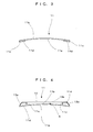
- FIG. 3 to FIG. 6 illustrate cross sections of the back plate member 11, respectively, and FIG. 3 is a section taken on line A-A in FIG. 2; FIG.
- FIG. 4 is a section taken on line B-B in FIG. 2;
- FIG. 5 is a section taken on line C-C in FIG. 2; and
- FIG. 6 is a section taken on line D-D in FIG. 2.
- FIG. 7 is a longitudinal section of the back plate member 11.
- FIG. 3 illustrates a cross section of a portion of the back plate member 11 that is above the reinforcing member 13 and close to the uppermost portion. The whole is curved such that it is slightly warped toward the side of the rear face 11b. Both of side edge parts 11c of the back plate member 11 are slightly bulged from the front face 11a of the back plate member 11, the inside of the respective side edge parts 11c being made hollow. This side edge part 11c provides an effect of improving the strength of the back plate member 11.
- FIG. 4 illustrates a section of a portion located lower than the level of the section as illustrated in FIG. 3.
- a smooth curved surface is formed from the side edge part 11c on one side of the front face 11a to the side edge part 11c on the other side thereof, and in the same manner as at the level as indicated in FIG. 3, the whole is curved such that it is slightly warped toward the side of the rear face 11b.
- the side edge part 11c is bulged toward the side of the rear face 11b unlike that at the level as indicated in FIG. 3.
- the hollow part 11d of the side edge part 11c is larger than that at the level as indicated in FIG. 3.
- the side edge part 11c provides an effect of improving the strength of the back plate member 11.
- the reinforcing member 13 is provided such that it covers the side edge parts 11c.
- the reinforcing member 13 is formed as a part unintegral with the back plate member 11, being made up of both of side parts 13a , 13a which cover the side edge parts 11c, and a front part 13b which continuously extends from both of the side parts 13a, 13a to form a spacing S between it and the rear face 11b of the back plate member 11.
- the spacing S is used as a pocket P as described later.
- FIG. 5 illustrates a section of a portion located lower than the level of the section as illustrated in FIG. 4. Also at this level, the whole is curved such that it is slightly warped toward the side of the rear face 11b. In addition, the side edge part 11c and the hollow part 11d are made larger, with the spacing S being made still larger.
- FIG. 6 illustrates a section of a portion located lower than the level of the section as illustrated in FIG. 5 and at substantially the same level of the armrest 30. Also at this level, the whole is curved such that it is slightly warped toward the side of the rear face 11b. In addition, the geometry of the side edge part 11c is changed into that which is bulged slenderly toward the rear. At this level, a portion is provided which continues to the reinforcing member 13, but there is no spacing S between that portion and the front face 11a of the back plate member 11, and thus, no pocket P is produced.
- the side edge part 11c and the hollow part 11d as shown in FIG. 3 to FIG. 6 are continuously changed in the geometry of the cross section.
- the back plate member 11 has a strength which is further improved by the side edge parts 11c, however, in the inside of the side edge parts 11c, a hollow part 11d is formed, thus the increase in weight of the seat back 10 is extremely small.
- the longitudinal section of the back plate member 11 is formed as a curved surface in the shape of a letter S that is extremely gradually changed.
- the curved surface geometry as indicated by this longitudinal section, and the curved surface geometries as indicated by said cross sections enhance the surface rigidity of the back plate member 11.
- the back plate member 11 is ergonomically formed to have a geometry which allows a sitting person to obtain a comfortable feeling.
- the upper end part and the lower end part of the back plate member 11 are formed to be hollow, respectively. Thereby, weight reduction is achieved.
- a flange 18 is provided in the central part of the rear face 11b. This flange 18 is located where it supports the lower part of the reinforcing member 13, forming a bottom part of the pocket P.
- the flange 18 may fully block the lower part of the reinforcing member 13 , or block to such a degree that the articles contained in the pocket P will not be dropped off.
- the location where said reinforcing member 13 is formed is at a level higher than the table 40 being in service, which is indicated with alternate long and two short dashes lines in FIG. 1 and FIG. 2.
- the pocket P has a depth which is deep enough to vertically contain a magazine M.
- a putting-in and taking-out opening 14 for putting articles in and taking them out of the pocket P is formed so as to be directed upward by the rear face 11b of the back plate member 11 and an upper edge part 13c of the reinforcing member 13. This putting-in and taking-out opening 14 is formed into an oblong opening along the rear face 11b.
- the reinforcing member 13 is provided with a taking-out opening 15 in the front part 13b.
- the lower edge part of the taking-out opening 15 is at a level higher than the bottom part of the pocket P. Also from this taking-out opening 15, articles can be put in and taken out of the pocket P.
- This taking-out opening 15 can be blocked by the table 40 not being in service.
- the table 40 is freely rotatably pivoted at the rear end thereof, being held between the tip ends of two arms 50 which basal ends are freely rotatably pivoted. At the time when the table 40 is not in service, a resting face 41 for articles thereof can be caused to be held, being positioned along the front part 13b of the reinforcing member 13.
- a recess is formed such that, when the table 40 is held, practically no step height differences are produced between a rear face 42, which is on the opposite side of the resting face 41, and the surface of the front part 13b.
- the table 40 is accommodated in this recess, it is held such that a feeling of integrity between it and the reinforcing member 13 is created.
- a table holding part 17 for holding the table 40 is provided in the vicinity of the putting-in and taking-out opening 14.
- the table holding part 17 is made up of a concave part 17a which is slightly recessed from the surface of the reinforcing member 13, and a rotating member 17b which is freely rotatably provided in the concave part 17a.
- a concave part 42a which is slightly recessed is provided.
- the concave part 42a and the concave part 17a of the table holding part 17 are made substantially flush with each other, thus by turning the rotating member 17b in order to cause a part of the rotating member 17b to be engaged with the concave part 42a, the table 40 can be held.
- the respective installing members 60, 70 may be of any configuration, provided that they are a pair of members which can seize or fit to each other.
- the installing member 60 is a hook and pile fastener 60
- another installing member 70 is a fitting rail 70 which components fit to each other.
- the hook and pile fastener 60 is made up of a pair of components, i.e., a first tape 61 (a first component) that a number of hook-like parts are formed over substantially the entire surface of the front face, and a second tape 62 (a second component) that a number of pile-like parts are formed over substantially the entire surface of the front face.
- a first tape 61 a first component
- a second tape 62 a second component
- the first tape 61 is attached in the longitudinal direction (vertical direction) of the back plate member 11 along both sides of the front face 11a
- the second tape 62 is attached in the longitudinal direction (vertical direction) of the cushion 12 along both sides of the installation face of the cushion 12.
- a combination of the first tape 61 with the second tape 62 is used as the hook and pile fastener 60
- either of the first tape 61 and the second tape 62 may be mounted to the front face 11a or the installation face of the cushion 12.
- the fitting rail 70 is made up of a pair of components, i.e. , a convex rail 71 that a convex part 71a extends in the longitudinal direction, as shown in FIG. 9 (A), and a concave rail 72 that a concave part 72a extends in the longitudinal direction as shown in FIG. 9(B), and the convex part 71a and the concave part 72a fit to each other.
- the convex rail 71 is mounted to the upper end part of the front face 11a in the lateral direction
- the concave rail 72 is mounted to the upper end part of the installation face of the cushion 12 in the lateral direction. So long as a combination of the convex rail 71 with the concave rail 72 is used as the fitting rail 70, either of the convex rail 71 and the concave rail 72 may be mounted to the front face 11a or the installation face of the cushion 12.
- the installation face thereof may be formed such that it is along the curved surface geometry of the front face 11a. Further, the geometry of the entire cushion 12 may be adapted to be that which is along the curved surface geometry of the front face 11a.
- the cushion 12 is installed onto the front face 11a of the back plate member 11, and on the rear face 11b, the reinforcing member 13, which is unintegral with the back plate member 11, is fixedly installed.
- the reinforcing member 13 is disposed in a location where the lower end part thereof is supported by the flange 18.
- one end of the concave part 72a of the concave rail 72 mounted to the upper end part of the installation face of the cushion 12 is fitted to the convex part 71a of the convex rail 71 mounted to the upper part of the front face 11a at one end thereof, and is slid to fit the entire concave part 72a to the convex part 71a.
- the cushion 12 is aligned to the front face 11a, and the first tape 61 attached to the front face 11a and the second tape 62 attached to the cushion 12 can be caused to be tightly contacted with each other for their seizing each other.
- the installation face of the cushion 12 By forming the installation face of the cushion 12 such that it is along the curved surface geometry of the rear face 11b, said installation working can be made easier. In addition, even in the case that the thickness of the cushion 12 is decreased, the comfortable feeling which is brought about by the curved surface geometry of the front face 11a can be provided without being impaired.
- the back plate member 11 is provided with an improvement in surface rigidity by making the surface curved, and with a reinforcement by the reinforcing member 13, the back plate member 11 can be made thinner and the need for using a seat back frame for reinforcement is eliminated. Therefore, there is no need for offsetting the step height difference between the back plate member 11 and the seat back frame by increasing the thickness of the cushion 12, thus the cushion 12 can provide only the original function as a cushion, having a minimum thickness required. As a result of this, the entire seat back 10 can be made thinner, and the sitting space can be expanded. In addition, the weight of the seat back 10 can be reduced, and the number of parts can be reduced.
- the putting-in and taking-out opening 14 of the pocket P which is formed on the rear face 11b of the back plate member 11 is directed upward, and above the putting-in and taking-out opening 14, there is nothing which hinders an article from being put in and taken out through the putting-in and taking-out opening 14, thus an article can be easily put in and taken out by one hand.
- a relatively long article such as a magazine or a folded newspaper can be placed straight into the pocket P from above without being bent halfway.
- the opening plane of the putting-in and taking-out opening 14 is gradually inclined downward from the rear face 11b of the back plate member 11, thus the opening area is wide, and the sitting person on the rear seat can directly view the putting-in and taking-out opening 14, which makes it easier to put articles in and take them out of the pocket P.
- the table 40 which can be held in the front part 13b of the reinforcing member 13 will have no influence on the operation of putting-in and taking-out of an article through the putting-in and taking-out opening 14, in either of the held state that it is held in the holding position, not being in service, and the servicing state that it is turned downward from the holding position to the front of the sitting person on the rear seat for service.
- the taking-out opening 15 formed in the front part 13b of the reinforcing member 13 is exposed in front of the sitting person, thus through this taking-out opening 15, an article can be put in and taken out of the pocket P.
- the side edge may be bent forward continuously from the front face 11a as an integral part to form a side edge part which inside is hollow, whereby the strength of the back plate member 11 is enhanced.
- the side edge part may be formed such that the body sides of the sitting person are supported.
- the reinforcing member 13 may be formed as an integral part of the back plate member 11.
- the installing member is not limited to said examples, provided that the components thereof have a configuration for fitting to each other, or seize each other.
- the back plate member is formed in the shape of a curved surface, resulting in the surface rigidity being enhanced, and in addition, is reinforced by means of the reinforcing member, whereby mainly the back plate member can receive the load imposed thereon by a sitting person, thus the need for using a seat back frame to reinforce the back plate member is eliminated, which allows the seat back to be rendered slim.
- the sacrifice of the sitting space that results from the thickness of the seat back is minimized, thus the sitting space can be enlarged.
- the weight of the seat can be reduced with the number of parts being reduced, which leads to reduction in the manufacturing cost.
- the curved surface of the back plate member have a geometry which can maintain the sitting person at a comfortable posture; thereby an effect of bringing about a comfortable posture is exerted, even if the cushion is thinned, thus by thinning the cushion, the seat back can be rendered still slimmer, which makes it possible to further enlarge the sitting space.
- the cushion be formed to have a geometry which is along the curved surface of the back plate member; thereby the installation of the cushion onto the back plate member is facilitated, and the comfortable feeling can be brought about by the curved surface of the back plate member as it is, which provides a more comfortable seat.
- the void between the reinforcing member and the rear face of the back plate member is formed as a pocket, and the opening for putting articles in and taking them out of this pocket is directed upward, thus even a relatively long article, such as a magazine, a newspaper, or the like, can be easily put in and taken out by one hand.
- the side edge of the back plate member may be bent forward or rearward continuously from the front face as an integral part to form a side edge part, and the side edge part may be formed to be hollow; thereby, the strength of the back plate member can be further improved, and because the side edge part is hollow, the increase in the weight of the back plate member can be held to a minimum.
- an installing member for removably installing the cushion onto the front face of the back plate member be provided, and with the installing member, a first component thereof provided on the front face of the back plate member and a second component thereof provided on the cushion seize each other, thus the cushion can be installed onto the front face of the back plate member, and the seizure can be cancelled for easily separating the cushion from the back plate member.
Applications Claiming Priority (2)
| Application Number | Priority Date | Filing Date | Title |
|---|---|---|---|
| JP2005056172A JP4260124B2 (ja) | 2005-03-01 | 2005-03-01 | 航空機用座席 |
| PCT/JP2006/303552 WO2006093072A1 (ja) | 2005-03-01 | 2006-02-27 | 航空機用座席 |
Publications (3)
| Publication Number | Publication Date |
|---|---|
| EP1854718A1 true EP1854718A1 (de) | 2007-11-14 |
| EP1854718A4 EP1854718A4 (de) | 2009-02-11 |
| EP1854718B1 EP1854718B1 (de) | 2010-07-14 |
Family
ID=36941101
Family Applications (1)
| Application Number | Title | Priority Date | Filing Date |
|---|---|---|---|
| EP06714689A Expired - Fee Related EP1854718B1 (de) | 2005-03-01 | 2006-02-27 | Flugzeugsitz |
Country Status (7)
| Country | Link |
|---|---|
| US (1) | US8020936B2 (de) |
| EP (1) | EP1854718B1 (de) |
| JP (1) | JP4260124B2 (de) |
| CN (1) | CN100519338C (de) |
| DE (1) | DE602006015434D1 (de) |
| HK (1) | HK1117114A1 (de) |
| WO (1) | WO2006093072A1 (de) |
Cited By (6)
| Publication number | Priority date | Publication date | Assignee | Title |
|---|---|---|---|---|
| EP2110313A2 (de) * | 2004-01-29 | 2009-10-21 | Recaro Aircraft Seating GmbH & Co.KG. | Fluggastsitz |
| DE202010002082U1 (de) * | 2010-02-08 | 2011-06-09 | ZIM GmbH, 88677 | Flugzeugsitz-Rückenlehne sowie Flugzeugsitz |
| DE202010002083U1 (de) * | 2010-02-08 | 2011-06-09 | ZIM GmbH, 88677 | Flugzeugsitz-Rückenlehne und Flugzeugsitz |
| FR2990659A1 (fr) * | 2012-05-15 | 2013-11-22 | Faurecia Sieges Automobile | Dossier de siege pour vehicule automobile |
| DE102014219984A1 (de) * | 2014-10-01 | 2016-04-07 | Bombardier Transportation Gmbh | Sitzschale und Verfahren zur Herstellung einer Sitzschale |
| DE102014119598A1 (de) * | 2014-12-23 | 2016-06-23 | Recaro Aircraft Seating Gmbh & Co. Kg | Sitzvorrichtung |
Families Citing this family (33)
| Publication number | Priority date | Publication date | Assignee | Title |
|---|---|---|---|---|
| CN105539853B (zh) | 2009-01-30 | 2018-08-28 | 新西兰航空公司 | 座椅布置、座椅单元、托盘桌以及座椅系统 |
| CN101575006B (zh) * | 2009-06-05 | 2011-05-04 | 吴速 | 由飞机乘客座椅前的餐板集成的媒体及通信系统 |
| DE102009024702A1 (de) * | 2009-06-12 | 2010-12-16 | Recaro Aircraft Seating Gmbh & Co. Kg | Passagiersitzvorrichtung |
| WO2011018930A1 (ja) | 2009-08-13 | 2011-02-17 | 株式会社デルタツーリング | 乗物用シート |
| USD665182S1 (en) | 2010-01-14 | 2012-08-14 | Air New Zealand Limited | Aircraft seat unit |
| CN102126557B (zh) * | 2011-01-05 | 2013-12-25 | 张培霞 | 一种载客飞机空中紧急情况救生系统 |
| JP5908062B2 (ja) * | 2011-04-15 | 2016-04-26 | ジョンソン・コントロールズ・ゲー・エム・ベー・ハー | プラスチック製の車両構造要素とその製造方法 |
| JP6026634B2 (ja) * | 2012-03-14 | 2016-11-16 | ビーイー・エアロスペース・インコーポレーテッドB/E Aerospace, Inc. | 複合座席フレーム用の一体成形された座席背もたれおよび方法 |
| JP5847983B2 (ja) * | 2012-03-23 | 2016-01-27 | ビーイー・エアロスペース・インコーポレーテッドB/E Aerospace, Inc. | 乗客用座席のリクライニングおよびトレイテーブルの支持機構 |
| CN102963529B (zh) * | 2012-11-30 | 2016-06-01 | 湖北航宇嘉泰飞机设备有限公司 | 轻型航空旅客座椅 |
| USD750392S1 (en) | 2013-08-20 | 2016-03-01 | Encore Interiors, Inc. | Aircraft seat |
| US9630717B2 (en) | 2013-04-26 | 2017-04-25 | Encore Interiors, Inc. | Aircraft seating assembly with reduced spacing |
| SG2013052030A (en) * | 2013-07-04 | 2015-02-27 | Singapore Tech Aerospace Ltd | A seatback for a passenger seat |
| USD775843S1 (en) * | 2014-03-27 | 2017-01-10 | Man Truck & Bus Ag | Vehicle seat |
| US9457731B2 (en) * | 2014-05-27 | 2016-10-04 | Honda Motor Co., Ltd. | Integrated device holder assembly and methods of use and manufacture thereof |
| USD807668S1 (en) * | 2014-12-02 | 2018-01-16 | Kehei Traveler Corporation | Seat cover |
| US11014676B2 (en) * | 2015-02-11 | 2021-05-25 | MIRUS Aircraft Seating Ltd. | Lightweight aircraft passenger seat assembly |
| CN104802995B (zh) * | 2015-04-10 | 2016-11-23 | 同济大学 | 一种用于轻量化航空座椅的承载结构部件 |
| US9764844B2 (en) | 2015-04-13 | 2017-09-19 | Encore Seats, Inc. | Aircraft seating assembly |
| JP6494102B2 (ja) * | 2015-06-10 | 2019-04-03 | 株式会社オカムラ | 椅子 |
| CN105034910B (zh) * | 2015-07-09 | 2018-03-20 | 苏州云逸航空复合材料结构有限公司 | 交通工具用座椅 |
| WO2017173400A1 (en) | 2016-04-01 | 2017-10-05 | Encore Seats, Inc. | Aircraft seating assembly and components |
| WO2018057117A1 (en) * | 2016-09-26 | 2018-03-29 | Zodiac Seats Us Llc | Amenities panel for passenger seat for holding passenger belongings and devices |
| DE202016106446U1 (de) * | 2016-11-17 | 2017-01-27 | Lear Corporation | Kartenfachanordnung |
| USD861537S1 (en) * | 2017-03-02 | 2019-10-01 | Newtl | Bus |
| US10065741B1 (en) | 2017-04-11 | 2018-09-04 | B/E Aerospace, Inc. | Illuminated literature pocket for aircraft passenger seat |
| WO2018190810A1 (en) * | 2017-04-11 | 2018-10-18 | B/E Aerospace, Inc. | Illuminated literature pocket for aircraft passenger seat |
| US10766622B2 (en) | 2017-10-23 | 2020-09-08 | Yaborã Indústria Aeronáutica S.A. | Lightweight vehicle passenger seat assemblies |
| US11603024B2 (en) * | 2017-12-21 | 2023-03-14 | Adient Aerospace Llc | Seating module having a recessed grip and a seating arrangement including a seating module having a recessed grip |
| US10569688B2 (en) * | 2017-12-21 | 2020-02-25 | Adient Aerospace Llc | Seating module having a recessed grip and a seating arrangement including a seating module having a recessed grip |
| USD903349S1 (en) * | 2018-04-23 | 2020-12-01 | Autoflug Gmbh | Seat for means of transport |
| US11180254B2 (en) | 2019-05-24 | 2021-11-23 | AirGo Design Pte., Ltd. | Space-efficient flat-bed seating arrangement |
| CN110155343B (zh) * | 2019-05-28 | 2020-10-09 | 北京安达维尔航空设备有限公司 | 双向三联抗坠毁座椅 |
Citations (4)
| Publication number | Priority date | Publication date | Assignee | Title |
|---|---|---|---|---|
| US5133587A (en) * | 1989-11-20 | 1992-07-28 | Hadden Jr James R | Seat |
| JP2000272597A (ja) * | 1998-11-12 | 2000-10-03 | Mgr Foamtex Ltd | 航空機用座席 |
| WO2002032268A1 (en) * | 2000-10-20 | 2002-04-25 | William Ashley Donlan | Seat signage and associated sales systems |
| WO2005073083A1 (de) * | 2004-01-29 | 2005-08-11 | Recaro Aircraft Seating Gmbh & Co. Kg | Fluggastsitz |
Family Cites Families (17)
| Publication number | Priority date | Publication date | Assignee | Title |
|---|---|---|---|---|
| US3182377A (en) * | 1963-11-29 | 1965-05-11 | American Seating Co | Theater chair backs and method of cushion assembly |
| US3695689A (en) * | 1970-04-22 | 1972-10-03 | American Seating Co | Vehicular safety chair |
| US4088367A (en) * | 1977-06-20 | 1978-05-09 | Rohr Industries, Inc. | Vehicle seat assembly |
| US4498702A (en) * | 1982-06-11 | 1985-02-12 | Steelcase Inc. | Seating unit with front flex area |
| JPS61156552A (ja) | 1984-12-28 | 1986-07-16 | Nippon Kokan Kk <Nkk> | 長時間記録装置 |
| DE8709523U1 (de) * | 1987-07-10 | 1987-09-10 | Keiper Recaro Gmbh & Co, 5630 Remscheid, De | |
| EP0572558B1 (de) * | 1991-02-20 | 1997-07-09 | Jay Medical, Ltd. | System für den rücken bei missbildung |
| US5152582A (en) * | 1991-03-28 | 1992-10-06 | American Seating Company | Self-aligning fastener system having stud-engaging resilient legs |
| US5292174A (en) * | 1991-10-22 | 1994-03-08 | Tachi-S Co., Ltd. | Pocket structure in automotive seat |
| US5951110A (en) | 1997-10-17 | 1999-09-14 | Irwin Seating Company | Contoured plastic seat back |
| US6450571B1 (en) * | 1999-02-27 | 2002-09-17 | Lear Corporation | Seat back having pocket for storing a storage case |
| US6142561A (en) * | 1999-04-09 | 2000-11-07 | Daimlerchrysler Corporation | Removable seating unit having a pivoting seatback and a combination handle and item supporting device |
| DE19916593C2 (de) | 1999-04-13 | 2003-06-12 | Fast Ag Grenchen | Fluggastsitz |
| US6131993A (en) * | 1999-04-19 | 2000-10-17 | Daimlerchrysler Corporation | Seat back panel |
| JP3088722B1 (ja) | 1999-08-23 | 2000-09-18 | 難波プレス工業株式会社 | リクライニング式の座席 |
| JP2001258681A (ja) * | 2000-03-17 | 2001-09-25 | Johnson Controls Automotive Systems Corp | 車両用シート |
| DE10232627A1 (de) * | 2002-07-18 | 2004-01-29 | Prospective Concepts Ag | Adaptives pneumatisches Sitz- und Lehnkissen für Fahr- und Flugzeuge |
-
2005
- 2005-03-01 JP JP2005056172A patent/JP4260124B2/ja not_active Expired - Fee Related
-
2006
- 2006-02-27 EP EP06714689A patent/EP1854718B1/de not_active Expired - Fee Related
- 2006-02-27 WO PCT/JP2006/303552 patent/WO2006093072A1/ja active Application Filing
- 2006-02-27 US US11/884,490 patent/US8020936B2/en active Active
- 2006-02-27 CN CNB2006800046297A patent/CN100519338C/zh not_active Expired - Fee Related
- 2006-02-27 DE DE602006015434T patent/DE602006015434D1/de active Active
-
2008
- 2008-07-03 HK HK08107360.9A patent/HK1117114A1/xx not_active IP Right Cessation
Patent Citations (4)
| Publication number | Priority date | Publication date | Assignee | Title |
|---|---|---|---|---|
| US5133587A (en) * | 1989-11-20 | 1992-07-28 | Hadden Jr James R | Seat |
| JP2000272597A (ja) * | 1998-11-12 | 2000-10-03 | Mgr Foamtex Ltd | 航空機用座席 |
| WO2002032268A1 (en) * | 2000-10-20 | 2002-04-25 | William Ashley Donlan | Seat signage and associated sales systems |
| WO2005073083A1 (de) * | 2004-01-29 | 2005-08-11 | Recaro Aircraft Seating Gmbh & Co. Kg | Fluggastsitz |
Non-Patent Citations (1)
| Title |
|---|
| See also references of WO2006093072A1 * |
Cited By (7)
| Publication number | Priority date | Publication date | Assignee | Title |
|---|---|---|---|---|
| EP2110313A2 (de) * | 2004-01-29 | 2009-10-21 | Recaro Aircraft Seating GmbH & Co.KG. | Fluggastsitz |
| EP2110313B1 (de) * | 2004-01-29 | 2015-01-07 | Recaro Aircraft Seating GmbH & Co. KG | Fluggastsitz |
| DE202010002082U1 (de) * | 2010-02-08 | 2011-06-09 | ZIM GmbH, 88677 | Flugzeugsitz-Rückenlehne sowie Flugzeugsitz |
| DE202010002083U1 (de) * | 2010-02-08 | 2011-06-09 | ZIM GmbH, 88677 | Flugzeugsitz-Rückenlehne und Flugzeugsitz |
| FR2990659A1 (fr) * | 2012-05-15 | 2013-11-22 | Faurecia Sieges Automobile | Dossier de siege pour vehicule automobile |
| DE102014219984A1 (de) * | 2014-10-01 | 2016-04-07 | Bombardier Transportation Gmbh | Sitzschale und Verfahren zur Herstellung einer Sitzschale |
| DE102014119598A1 (de) * | 2014-12-23 | 2016-06-23 | Recaro Aircraft Seating Gmbh & Co. Kg | Sitzvorrichtung |
Also Published As
| Publication number | Publication date |
|---|---|
| US20100155536A1 (en) | 2010-06-24 |
| CN100519338C (zh) | 2009-07-29 |
| WO2006093072A1 (ja) | 2006-09-08 |
| CN101115656A (zh) | 2008-01-30 |
| DE602006015434D1 (de) | 2010-08-26 |
| JP2006240379A (ja) | 2006-09-14 |
| HK1117114A1 (en) | 2009-01-09 |
| EP1854718A4 (de) | 2009-02-11 |
| EP1854718B1 (de) | 2010-07-14 |
| JP4260124B2 (ja) | 2009-04-30 |
| US8020936B2 (en) | 2011-09-20 |
Similar Documents
| Publication | Publication Date | Title |
|---|---|---|
| EP1854718B1 (de) | Flugzeugsitz | |
| US20090058154A1 (en) | Vehicle seat assembly | |
| US6499787B2 (en) | Collapsible vehicle seat assemblies | |
| US8109565B2 (en) | Automotive seat reconfigurable to work desk | |
| US6786544B1 (en) | Seat back structure of vehicle seat | |
| EP1908628A1 (de) | Fahrzeugsitz und fahrzeugsitzmontageverfahren | |
| US20120234455A1 (en) | Method for producing a rear wall of a seat backrest | |
| EP2108541A1 (de) | Kraftfahrzeugsitzverstaustruktur | |
| US9796310B1 (en) | Composite one-piece cushion nose | |
| US20170320415A1 (en) | Lightweight Seat for Vehicles | |
| JP6686698B2 (ja) | 乗物用シート | |
| JP2012101661A (ja) | シートバック構造 | |
| US11285848B2 (en) | Armrest of vehicle seat | |
| US10632887B2 (en) | Headrest storage structure | |
| JP6347244B2 (ja) | 車両のシート構造 | |
| JP5467762B2 (ja) | 乗り物用シート構造 | |
| JP7295772B2 (ja) | 乗物用シート | |
| JP4176807B2 (ja) | 自動車用シートの格納構造 | |
| JP4984109B2 (ja) | 車両の室内構造 | |
| JP7323760B2 (ja) | 車両用内装部材 | |
| JP2607251Y2 (ja) | 市内路線バスにおける座席構造 | |
| JP2014210536A (ja) | シート装置 | |
| CN218343332U (zh) | 座椅扶手、座椅组件、交通工具 | |
| US11760243B2 (en) | Armrest | |
| JP2006168727A (ja) | 2通りに使用可能な座席 |
Legal Events
| Date | Code | Title | Description |
|---|---|---|---|
| PUAI | Public reference made under article 153(3) epc to a published international application that has entered the european phase |
Free format text: ORIGINAL CODE: 0009012 |
|
| 17P | Request for examination filed |
Effective date: 20070809 |
|
| AK | Designated contracting states |
Kind code of ref document: A1 Designated state(s): DE FR GB IT |
|
| RBV | Designated contracting states (corrected) |
Designated state(s): DE FR GB IT |
|
| DAX | Request for extension of the european patent (deleted) | ||
| A4 | Supplementary search report drawn up and despatched |
Effective date: 20090113 |
|
| 17Q | First examination report despatched |
Effective date: 20090520 |
|
| GRAJ | Information related to disapproval of communication of intention to grant by the applicant or resumption of examination proceedings by the epo deleted |
Free format text: ORIGINAL CODE: EPIDOSDIGR1 |
|
| GRAP | Despatch of communication of intention to grant a patent |
Free format text: ORIGINAL CODE: EPIDOSNIGR1 |
|
| GRAP | Despatch of communication of intention to grant a patent |
Free format text: ORIGINAL CODE: EPIDOSNIGR1 |
|
| GRAS | Grant fee paid |
Free format text: ORIGINAL CODE: EPIDOSNIGR3 |
|
| GRAA | (expected) grant |
Free format text: ORIGINAL CODE: 0009210 |
|
| AK | Designated contracting states |
Kind code of ref document: B1 Designated state(s): DE FR GB IT |
|
| REG | Reference to a national code |
Ref country code: GB Ref legal event code: FG4D |
|
| REF | Corresponds to: |
Ref document number: 602006015434 Country of ref document: DE Date of ref document: 20100826 Kind code of ref document: P |
|
| PLBE | No opposition filed within time limit |
Free format text: ORIGINAL CODE: 0009261 |
|
| STAA | Information on the status of an ep patent application or granted ep patent |
Free format text: STATUS: NO OPPOSITION FILED WITHIN TIME LIMIT |
|
| 26N | No opposition filed |
Effective date: 20110415 |
|
| REG | Reference to a national code |
Ref country code: DE Ref legal event code: R097 Ref document number: 602006015434 Country of ref document: DE Effective date: 20110415 |
|
| PGFP | Annual fee paid to national office [announced via postgrant information from national office to epo] |
Ref country code: IT Payment date: 20120215 Year of fee payment: 7 |
|
| PGFP | Annual fee paid to national office [announced via postgrant information from national office to epo] |
Ref country code: DE Payment date: 20130220 Year of fee payment: 8 Ref country code: FR Payment date: 20130301 Year of fee payment: 8 Ref country code: GB Payment date: 20130228 Year of fee payment: 8 |
|
| REG | Reference to a national code |
Ref country code: DE Ref legal event code: R119 Ref document number: 602006015434 Country of ref document: DE |
|
| GBPC | Gb: european patent ceased through non-payment of renewal fee |
Effective date: 20140227 |
|
| REG | Reference to a national code |
Ref country code: FR Ref legal event code: ST Effective date: 20141031 |
|
| REG | Reference to a national code |
Ref country code: DE Ref legal event code: R119 Ref document number: 602006015434 Country of ref document: DE Effective date: 20140902 |
|
| PG25 | Lapsed in a contracting state [announced via postgrant information from national office to epo] |
Ref country code: GB Free format text: LAPSE BECAUSE OF NON-PAYMENT OF DUE FEES Effective date: 20140227 Ref country code: FR Free format text: LAPSE BECAUSE OF NON-PAYMENT OF DUE FEES Effective date: 20140228 Ref country code: DE Free format text: LAPSE BECAUSE OF NON-PAYMENT OF DUE FEES Effective date: 20140902 |
|
| PG25 | Lapsed in a contracting state [announced via postgrant information from national office to epo] |
Ref country code: IT Free format text: LAPSE BECAUSE OF NON-PAYMENT OF DUE FEES Effective date: 20140227 |
|
| P01 | Opt-out of the competence of the unified patent court (upc) registered |
Effective date: 20230510 |