EP1853086B1 - A/v amplifier and method for driving the same - Google Patents
A/v amplifier and method for driving the same Download PDFInfo
- Publication number
- EP1853086B1 EP1853086B1 EP06714363.6A EP06714363A EP1853086B1 EP 1853086 B1 EP1853086 B1 EP 1853086B1 EP 06714363 A EP06714363 A EP 06714363A EP 1853086 B1 EP1853086 B1 EP 1853086B1
- Authority
- EP
- European Patent Office
- Prior art keywords
- channel
- amplifiers
- amplifier
- reproduction mode
- decoder
- Prior art date
- Legal status (The legal status is an assumption and is not a legal conclusion. Google has not performed a legal analysis and makes no representation as to the accuracy of the status listed.)
- Ceased
Links
- 238000000034 method Methods 0.000 title claims description 9
- 238000010586 diagram Methods 0.000 description 7
- 230000000694 effects Effects 0.000 description 4
- 230000006870 function Effects 0.000 description 3
- 230000037361 pathway Effects 0.000 description 3
- 230000008878 coupling Effects 0.000 description 2
- 238000010168 coupling process Methods 0.000 description 2
- 238000005859 coupling reaction Methods 0.000 description 2
- 238000013016 damping Methods 0.000 description 2
- 230000001360 synchronised effect Effects 0.000 description 2
- 230000003247 decreasing effect Effects 0.000 description 1
- 230000003111 delayed effect Effects 0.000 description 1
- 238000005070 sampling Methods 0.000 description 1
- 230000019491 signal transduction Effects 0.000 description 1
- 230000005236 sound signal Effects 0.000 description 1
- 230000003936 working memory Effects 0.000 description 1
Images


Classifications
-
- H—ELECTRICITY
- H04—ELECTRIC COMMUNICATION TECHNIQUE
- H04S—STEREOPHONIC SYSTEMS
- H04S5/00—Pseudo-stereo systems, e.g. in which additional channel signals are derived from monophonic signals by means of phase shifting, time delay or reverberation
- H04S5/02—Pseudo-stereo systems, e.g. in which additional channel signals are derived from monophonic signals by means of phase shifting, time delay or reverberation of the pseudo four-channel type, e.g. in which rear channel signals are derived from two-channel stereo signals
-
- H—ELECTRICITY
- H03—ELECTRONIC CIRCUITRY
- H03F—AMPLIFIERS
- H03F3/00—Amplifiers with only discharge tubes or only semiconductor devices as amplifying elements
- H03F3/181—Low-frequency amplifiers, e.g. audio preamplifiers
-
- H—ELECTRICITY
- H03—ELECTRONIC CIRCUITRY
- H03F—AMPLIFIERS
- H03F3/00—Amplifiers with only discharge tubes or only semiconductor devices as amplifying elements
- H03F3/20—Power amplifiers, e.g. Class B amplifiers, Class C amplifiers
- H03F3/21—Power amplifiers, e.g. Class B amplifiers, Class C amplifiers with semiconductor devices only
- H03F3/217—Class D power amplifiers; Switching amplifiers
-
- H—ELECTRICITY
- H03—ELECTRONIC CIRCUITRY
- H03F—AMPLIFIERS
- H03F3/00—Amplifiers with only discharge tubes or only semiconductor devices as amplifying elements
- H03F3/68—Combinations of amplifiers, e.g. multi-channel amplifiers for stereophonics
-
- H—ELECTRICITY
- H03—ELECTRONIC CIRCUITRY
- H03F—AMPLIFIERS
- H03F2200/00—Indexing scheme relating to amplifiers
- H03F2200/03—Indexing scheme relating to amplifiers the amplifier being designed for audio applications
Definitions
- the present invention relates to an A/V amplifier in which any of a multi-channel reproduction mode and a 2-channel stereo reproduction mode can be selected, and to a method for driving the A/V amplifier.
- Dolby Surround System For a stereo reproduction with a surround sound system using a multi-channel A/V amplifier, Dolby Surround System is widely known (ref. FIG. 2 in Patent Document 1).
- FIG. 5 illustrates a configuration of a conventional A/V amplifier 500 using Dolby Surround System.
- This A/V amplifier 500 includes four channels, i.e., three channels in front and one channel in rear.
- the decoder 502 Based on 2-channel (left and right) stereo reproduction signals L and R entered into the terminals 501L and 501R, the decoder 502 produces and outputs four signals in total, i.e., the front left and right outputs 503L and 503R (stereo), the rear output 503S (monaural; in Patent Document 1, outputs from two speakers), and the center output 503C, according to the internal logic.
- the above four output signals are amplified by the amplifiers 504A to 504D each provided for the respective outputs, and then sent to the speakers for each channel (in FIG. 5 , only the speakers 506L for L-channel and 506R are shown) via the terminals 505A to 505D to cause the respective speakers to produce a sound, thereby achieving a reproduction by the predetermined Dolby Surround system.
- Patent Document 1 Japanese Examined Utility Model Application 6-23119
- the amplifier 504A and the amplifier 504C are used for the L channel and the R channel, respectively, and the amplifier 504B connected to the C channel speaker and the amplifier 504D connected to the S channel speaker are not used, not contributing at all to the sound quality improvement upon the 2-channel reproduction.
- the present invention aims to solve the above conventional problem, and to provide an A/V amplifier achieving the sound quality improvement upon 2-channel stereo reproduction, by effectively utilizing the amplifier that was only used in the multi-channel reproduction mode.
- an A/V amplifier in which a multi-channel reproduction mode and a 2-channel stereo reproduction mode can be selectively switched comprises:
- the timing of noise in the output signals of the plurality of amplifiers is preferably varied by connecting delay circuits to the amplifiers in series.
- the switching circuit preferably includes a plurality of switches, and a control unit for controlling on and off of these pluralities of switches.
- the A/V amplifier comprises:
- the timing of noise in the output signal of said plurality of amplifiers is preferably varied by connecting delay circuits to said plurality of amplifiers in series.
- high quality sound is embodied with a parallel-drive bi-amplifier reproduction upon the 2-channel stereo reproduction to realize a significant improvement in sound quality at low cost, by adding a simple switching circuit and a delay circuit to a multi-channel A/V amplifier in a popular price range.
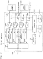
- FIG. 1 is a block diagram illustrating a connection arrangement of an A/V amplifier upon the multi-channel reproduction in an embodiment of the present invention
- FIG. 2 is a block diagram illustrating a connection arrangement of the same A/V amplifier upon the 2-channel stereo reproduction.
- reference numeral 102 refers to a Pro Logic decoder.
- the decoder 102 includes an input terminal unit 101, and to the input terminal unit 101, an input signal in which a 4-channel sound information and the like is encoded enters.
- the decoder 102 also includes the first to fourth signal sources, i.e., output terminals 103L, 103C, 103R, and 103S, from which signals for L-channel, C-channel, R-channel, and S-channel are output, respectively. Since the decoding method in the decoder 102 is known, its description is omitted.
- Reference numerals 104A to 104D refer to amplifiers.
- a PWM (pulse width modulation) amplifier is used for the amplifiers 104A to 104D.
- An input side of the amplifier 104A for L-channel, i.e., the first amplifier, is connected to the output terminal 103L of the decoder 102 via a switch S11.
- an output side is connected to the output terminal 105A for an L-channel speaker 106L, and further to an output side of the amplifier 104B for C-channel via a switch S1.
- An input side of the second amplifier i.e., the amplifier 104B, is connected to the output terminal 103C of the decoder 102 via a switch S2.
- an output side is connected to the output terminal 105A for a speaker 106L via a switch S1, and further to an output terminal 105B for a C-channel speaker (not shown), i.e., the second speaker, via a switch S3.
- a first delay circuit 107L is Also connected to the input side of the amplifier 104A, via a switch S12, is a first delay circuit 107L, between the input side of the amplifier 104A and the output terminal 103L of the decoder 102. Further, the input side of the amplifier 104B is connected, via a switch S5, to the output terminal 103L of the decoder 102.
- An input side of the amplifier 104C for R-channel i.e., the third amplifier, is connected to the output terminal 103R of the decoder 102 via a switch S13.
- an output side is connected to the output terminal 105C for an R-channel speaker 106R, i.e., the third speaker, and further to an output side of the amplifier 104D for S-channel, i.e., the fourth amplifier, via a switch S6.
- An input side of the amplifier 104D i.e., the fourth amplifier, is connected to the output terminal 103S of the decoder via a switch S7.
- an output side is connected to the output terminal 105D for a speaker 106R via a switch S6, and further to the output terminal 105D for an S-channel speaker (not shown), i.e., the fourth speaker, via a switch S9.
- a second delay circuit 107R is Also connected to the input side of the amplifier 104C, via a switch S14, is a second delay circuit 107R, between the input side of the amplifier 104C and the output terminal 103R of the decoder 102. Further, the input side of the amplifier 104D is connected, via a switch S10, to the output terminal 103R of the decoder 102.
- Reference numeral 108 is a control unit including a CPU (Central Processing Unit), and along with the switches S1 to S14, forms a switching circuit.
- the control unit 108 controls on and off of the switches S1 to S14, according to the selection information provided by a channel selecting unit 109.
- a channel selecting unit 109 For the switches S1 to S14, synchronized switches are used, so that the switches are simultaneously turned on or off.
- the channel selecting unit 109 is provided on an operation panel of the A/V amplifier 100, and operated by a user.
- the channel selecting unit 109 selects the 2-channel stereo reproduction mode or the 4-channel reproduction mode.
- Reference numeral 110 is a ROM in which an operation program of the control unit 108 is stored, and the control unit 108 carries out operations according to this operation program.
- Reference numeral 111 is a RAM.
- the RAM 103 functions as a working memory for storing various working data generated upon a program operation of the control unit 108.
- a multi-channel encoded source such as a movie and the like enters through the input terminal unit 101 of the decoder 102, is separated into four signals in the decoder 102, and is output to the output terminals 103L, 103C, 103R, and 103S.
- the control unit 108 turns on the switches S2, S3, S7, S9, S11, and S13, and turns off the switches S1, S5, S6, S10, S12, and S14.
- the output signal of the output terminal 103L of the decoder 102 is amplified at the amplifier 104A, since the switches S5 and S12 are open and the switch S11 is closed; and applied to the L-channel speaker 106L via the terminal 105 A, since the switch S1 is open, for a reproduction in the normal mode.
- the output of the output terminal 103R of the decoder 102 is amplified at the amplifier 104C, since the switches S10 and S14 are open and the switch S13 is closed; and applied to the R-channel speaker 106R via the terminal 105C, since the switch S6 is open, for a reproduction in the normal mode.
- the output signal of the output terminal 103C of the decoder 102 is amplified at the amplifier 104B, since the switch S2 is closed; and applied to the C-channel speaker via the terminal 105B to be reproduced, since the switch S1 is open and the switch S3 is closed.
- the output signal of the output terminal 103S of the decoder 102 is amplified at the amplifier 104D since the switch S7 is closed; and applied to the S-channel speaker via the terminal 105D to be reproduced, since the switch S6 is open and the switch S9 is closed.
- the delay circuits 107L and 107R are not in operation, since the switches S5, S10, S12, and S14 are open.
- the signals to be output from the decoder 102 are only for the L-channel and the R-channel.
- the control unit 108 closes the switches S1, S5, and S12, and opens the switches S2, S3, and S11.
- the output signal of the output terminal 103L of the decoder 102 enters the amplifier 104A from the switch S12 via the delay circuit 107L, and after being amplified by the amplifier 104A, output to the L-channel speaker 106L via the terminal 105A.
- the output signal of the output terminal 103L of the decoder 102 enters the amplifier 104B, i.e., the second amplifier for L-channel via the switch S5, and after being amplified at the amplifier 104B, output to the terminal 105A of the L-channel speaker 106L via the switch S1.
- the output signal of the output terminal 103L goes through two pathways, thereby driving the L-channel reproduction speaker 106L with the parallel-drive bi-amplifier system.
- the L-channel speaker 106L is driven at a low impedance; therefore, the effects of increasing the damping factor, which are effective in sound quality improvement of low-range component, can be expected.
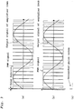
- FIG. 3 (a) to (c) show the output wave forms when the timing of the output signals of the amplifiers 104A and 104B is varied by the delay circuit 107L, instead of being synchronized; and the noise generated at that time.
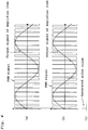
- FIG. 4(a) to (c) show the wave forms of the output signals of the amplifiers -104A and 104B when the delay circuit 107L is not provided; and the noise generated at that time.
- the noise is shown for just one wave form for a simple illustration.
- the delay duration may be set, for example, as in the following: when the sampling frequency Fs is 48 kHz, and a PWM modulator designed to enable a division into 256 relative to a wavelength of 1/4 is used, at least ⁇ (1/256) relative to the wavelength of 1/4 may be delayed.
- the delay duration is determined by considering the optimum value of distortion and the like in the circuit upon parallel-drive, setting the above value as the minimum value.
- the switches S6, S10, and S14 are closed, and the switches S7, S9, and S13 are open.
- the output signal of the output terminal 103R of the decoder 102 is separated to two: the pathway in which the signal goes through the delay circuit 107R and the switch S14, is amplified by the amplifier 104C, and then output from the terminal 105C to the R-channel speaker 106R; and the pathway in which the signal goes through the switch S10 and amplified by the fourth amplifier 104D for R-channel, and then connected to the output terminal 105C of the R-channel speaker 106R via the switch S6, thereby driving the bi-wiring reproduction speaker 106R for R-channel with the parallel-drive bi-amplifier system.
- the amplifier 104C i.e., the amplifier for R-channel and the amplifier 104D, i.e., the amplifier for S-channel are connected in parallel, thereby driving the R-channel speaker 106R with a low impedance; therefore, the effects of increasing the damping factor, which are effective in sound quality improvement of the low-range component, can be expected.
- the delay in one of the noises generated in the case of the non-feedback full digital amplifier can curb the overlay, and achieves direct coupling without being affected by the feedback circuit of the other amplifier.
- the amplifier for the multi-channel reproduction can be effectively utilized upon the 2-channel stereo reproduction, and the improvement in sound quality upon stereo reproduction can be achieved.
- the number of the switches can be decreased by using changeover switches for the switches S1 and S3, and the switches S6 and S9; removing the switches S2, S5, S7, S10, S11, S12, S13, and S14; providing changeover switches instead to the amplifiers 104A, 104B, 104C, and 104D.
- the position of the switches are not limited to those illustrated, and are satisfactory as long as the signal pathway can be switched between each of the amplifiers, the delay circuits, and the speakers for the connection that can bring out the effects of the present invention.
- the case when two amplifiers are driven in parallel is described, three or more amplifiers may be driven in parallel. In that case, the number of delay circuits necessary will be the number of amplifiers -1.
- the switches may be increased based on the configuration of FIG. 1 .
- An A/V amplifier of the present invention is highly industrially applicable, since the present invention contributes to the sound quality improvement of audio devices in which any of the multi-channel reproduction mode and the 2-channel stereo reproduction mode can be selected.
Landscapes
- Engineering & Computer Science (AREA)
- Power Engineering (AREA)
- Multimedia (AREA)
- Physics & Mathematics (AREA)
- Acoustics & Sound (AREA)
- Signal Processing (AREA)
- Amplifiers (AREA)
- Stereophonic System (AREA)
- Circuit For Audible Band Transducer (AREA)
Applications Claiming Priority (2)
| Application Number | Priority Date | Filing Date | Title |
|---|---|---|---|
| JP2005048351A JP4674474B2 (ja) | 2005-02-24 | 2005-02-24 | パラレル駆動バイアンプ切換回路 |
| PCT/JP2006/303223 WO2006090758A1 (ja) | 2005-02-24 | 2006-02-23 | Avアンプおよびその駆動方法 |
Publications (3)
| Publication Number | Publication Date |
|---|---|
| EP1853086A1 EP1853086A1 (en) | 2007-11-07 |
| EP1853086A4 EP1853086A4 (en) | 2011-04-06 |
| EP1853086B1 true EP1853086B1 (en) | 2018-04-04 |
Family
ID=36927396
Family Applications (1)
| Application Number | Title | Priority Date | Filing Date |
|---|---|---|---|
| EP06714363.6A Ceased EP1853086B1 (en) | 2005-02-24 | 2006-02-23 | A/v amplifier and method for driving the same |
Country Status (4)
| Country | Link |
|---|---|
| US (1) | US8081781B2 (enExample) |
| EP (1) | EP1853086B1 (enExample) |
| JP (1) | JP4674474B2 (enExample) |
| WO (1) | WO2006090758A1 (enExample) |
Families Citing this family (19)
| Publication number | Priority date | Publication date | Assignee | Title |
|---|---|---|---|---|
| US20060262936A1 (en) * | 2005-05-13 | 2006-11-23 | Pioneer Corporation | Virtual surround decoder apparatus |
| JP4197040B2 (ja) * | 2007-05-11 | 2008-12-17 | オンキヨー株式会社 | マルチチャンネル増幅器 |
| US8284963B2 (en) * | 2007-09-11 | 2012-10-09 | Texas Instruments Incorporated | Method and apparatus for diminishing mismatch effects between switched signals |
| JP4949193B2 (ja) * | 2007-10-23 | 2012-06-06 | ティーオーエー株式会社 | オーディオパワーアンプ |
| TW201019746A (en) * | 2008-11-05 | 2010-05-16 | Anpec Electronics Corp | Multi-channel output device for a multimedia device |
| US8494183B2 (en) | 2009-02-03 | 2013-07-23 | Onkyo Corporation | Audio processing apparatus |
| JP4471030B1 (ja) * | 2009-02-03 | 2010-06-02 | オンキヨー株式会社 | 音声処理装置 |
| US9426574B2 (en) | 2010-03-19 | 2016-08-23 | Bose Corporation | Automatic audio source switching |
| JP4997659B2 (ja) | 2010-04-02 | 2012-08-08 | オンキヨー株式会社 | 音声処理装置 |
| JP5444173B2 (ja) * | 2010-09-08 | 2014-03-19 | 株式会社東芝 | 増幅器及びアンプ制御方法 |
| US9543913B2 (en) * | 2013-01-09 | 2017-01-10 | Osc, Llc | Programmably configured switchmode audio amplifier |
| US10134295B2 (en) | 2013-09-20 | 2018-11-20 | Bose Corporation | Audio demonstration kit |
| US9997081B2 (en) | 2013-09-20 | 2018-06-12 | Bose Corporation | Audio demonstration kit |
| CN103702172A (zh) * | 2013-12-13 | 2014-04-02 | 乐视网信息技术(北京)股份有限公司 | 对音视频进行杜比转码的方法和系统 |
| TWI583206B (zh) * | 2015-07-15 | 2017-05-11 | 盛微先進科技股份有限公司 | 立體聲訊號驅動的裝置和方法 |
| WO2017164286A1 (ja) * | 2016-03-23 | 2017-09-28 | ヤマハ株式会社 | 音響機器の設定方法及び音響機器 |
| US11194607B2 (en) | 2018-01-16 | 2021-12-07 | Qsc, Llc | Cloud based audio / video operating systems |
| CN111602118B (zh) | 2018-01-16 | 2023-06-06 | Qsc公司 | 实现虚拟机的音频,视频和控制系统 |
| WO2019165317A2 (en) * | 2018-02-23 | 2019-08-29 | Qsc, Llc | Audio amplifier assemblies, processes, and methods |
Family Cites Families (12)
| Publication number | Priority date | Publication date | Assignee | Title |
|---|---|---|---|---|
| NL8105371A (nl) * | 1981-11-27 | 1983-06-16 | Philips Nv | Inrichting voor het aansturen van een of meer omzeteenheden. |
| JPS6047316A (ja) | 1983-08-23 | 1985-03-14 | 三菱電機株式会社 | パツフア式ガス遮断器 |
| JPS6047316U (ja) * | 1983-09-09 | 1985-04-03 | 日本コロムビア株式会社 | 増幅装置 |
| JPS60192512A (ja) * | 1984-03-13 | 1985-10-01 | 井関農機株式会社 | コンバイン播種機 |
| JPS60192512U (ja) * | 1984-05-30 | 1985-12-20 | 日本コロムビア株式会社 | 電力増幅器 |
| JPH0623119Y2 (ja) | 1989-01-24 | 1994-06-15 | パイオニア株式会社 | サラウンド方式ステレオ再生装置 |
| JPH0751169B2 (ja) | 1993-04-22 | 1995-06-05 | 株式会社三共 | パチンコ機 |
| JPH09271100A (ja) * | 1996-04-02 | 1997-10-14 | Nippon Columbia Co Ltd | 音響信号処理装置 |
| EP0866638B1 (en) | 1997-03-10 | 2011-06-15 | Panasonic Corporation | Audiovisual amplifier |
| US5875250A (en) * | 1998-02-02 | 1999-02-23 | Kuo; Mark | Single package three channel audio signal amplifier |
| JP2004048333A (ja) * | 2002-07-11 | 2004-02-12 | Victor Co Of Japan Ltd | Pwm変調方式d級アンプ |
| JP2006033499A (ja) * | 2004-07-16 | 2006-02-02 | Sony Corp | D級増幅器 |
-
2005
- 2005-02-24 JP JP2005048351A patent/JP4674474B2/ja not_active Expired - Fee Related
-
2006
- 2006-02-23 EP EP06714363.6A patent/EP1853086B1/en not_active Ceased
- 2006-02-23 US US11/814,791 patent/US8081781B2/en not_active Expired - Fee Related
- 2006-02-23 WO PCT/JP2006/303223 patent/WO2006090758A1/ja not_active Ceased
Non-Patent Citations (1)
| Title |
|---|
| None * |
Also Published As
| Publication number | Publication date |
|---|---|
| WO2006090758A1 (ja) | 2006-08-31 |
| US8081781B2 (en) | 2011-12-20 |
| US20090016539A1 (en) | 2009-01-15 |
| JP4674474B2 (ja) | 2011-04-20 |
| JP2006237928A (ja) | 2006-09-07 |
| EP1853086A4 (en) | 2011-04-06 |
| EP1853086A1 (en) | 2007-11-07 |
Similar Documents
| Publication | Publication Date | Title |
|---|---|---|
| EP1853086B1 (en) | A/v amplifier and method for driving the same | |
| US4953213A (en) | Surround mode stereophonic reproducing equipment | |
| EP0866638B1 (en) | Audiovisual amplifier | |
| NL192286C (nl) | Meerkanaalsaudioreproduktie-apparaat. | |
| US20040264717A1 (en) | Audio reproduction apparatus | |
| CA2507507A1 (en) | Multi-channel sound processing systems | |
| US5265166A (en) | Multi-channel sound simulation system | |
| JP2001103594A (ja) | オーディオ処理装置 | |
| US20040062402A1 (en) | Audio reproduction apparatus | |
| US6711270B2 (en) | Audio reproducing apparatus | |
| JP3436681B2 (ja) | Avアンプ | |
| JP2711152B2 (ja) | 多チャンネル音声信号再生装置 | |
| US5123051A (en) | Sound field reproducing apparatus | |
| JP2006050195A (ja) | Avアンプ | |
| JPH10215500A (ja) | テレビジョン受像機の多チャンネル音声出力回路 | |
| CA1321756C (en) | Sound field reproducing apparatus | |
| JP2003319487A (ja) | アコースティックサウンド再生装置 | |
| JPS61219300A (ja) | 多次元立体音場再生装置 | |
| JPH084799Y2 (ja) | ステレオ切換装置 | |
| CN2501273Y (zh) | 大功率、高保真环绕立体声电视机 | |
| KR200250865Y1 (ko) | 저주파 전용 차량용 음향 증폭기 | |
| JP2711151B2 (ja) | 多チャンネル音声再生装置 | |
| US20030198358A1 (en) | Loudspeaker arrangement and switching apparatus therefor | |
| WO2003061343A3 (en) | Surround-sound system | |
| JP2002112382A (ja) | 音響再生装置 |
Legal Events
| Date | Code | Title | Description |
|---|---|---|---|
| PUAI | Public reference made under article 153(3) epc to a published international application that has entered the european phase |
Free format text: ORIGINAL CODE: 0009012 |
|
| 17P | Request for examination filed |
Effective date: 20070718 |
|
| AK | Designated contracting states |
Kind code of ref document: A1 Designated state(s): DE GB |
|
| DAX | Request for extension of the european patent (deleted) | ||
| RBV | Designated contracting states (corrected) |
Designated state(s): DE GB |
|
| RAP1 | Party data changed (applicant data changed or rights of an application transferred) |
Owner name: PANASONIC CORPORATION |
|
| A4 | Supplementary search report drawn up and despatched |
Effective date: 20110304 |
|
| GRAP | Despatch of communication of intention to grant a patent |
Free format text: ORIGINAL CODE: EPIDOSNIGR1 |
|
| STAA | Information on the status of an ep patent application or granted ep patent |
Free format text: STATUS: GRANT OF PATENT IS INTENDED |
|
| INTG | Intention to grant announced |
Effective date: 20171009 |
|
| GRAS | Grant fee paid |
Free format text: ORIGINAL CODE: EPIDOSNIGR3 |
|
| GRAA | (expected) grant |
Free format text: ORIGINAL CODE: 0009210 |
|
| STAA | Information on the status of an ep patent application or granted ep patent |
Free format text: STATUS: THE PATENT HAS BEEN GRANTED |
|
| AK | Designated contracting states |
Kind code of ref document: B1 Designated state(s): DE GB |
|
| REG | Reference to a national code |
Ref country code: GB Ref legal event code: FG4D |
|
| REG | Reference to a national code |
Ref country code: DE Ref legal event code: R096 Ref document number: 602006055062 Country of ref document: DE |
|
| REG | Reference to a national code |
Ref country code: DE Ref legal event code: R097 Ref document number: 602006055062 Country of ref document: DE |
|
| PLBE | No opposition filed within time limit |
Free format text: ORIGINAL CODE: 0009261 |
|
| STAA | Information on the status of an ep patent application or granted ep patent |
Free format text: STATUS: NO OPPOSITION FILED WITHIN TIME LIMIT |
|
| 26N | No opposition filed |
Effective date: 20190107 |
|
| REG | Reference to a national code |
Ref country code: DE Ref legal event code: R119 Ref document number: 602006055062 Country of ref document: DE |
|
| GBPC | Gb: european patent ceased through non-payment of renewal fee |
Effective date: 20190223 |
|
| PG25 | Lapsed in a contracting state [announced via postgrant information from national office to epo] |
Ref country code: GB Free format text: LAPSE BECAUSE OF NON-PAYMENT OF DUE FEES Effective date: 20190223 Ref country code: DE Free format text: LAPSE BECAUSE OF NON-PAYMENT OF DUE FEES Effective date: 20190903 |