EP1849401B1 - Endoscope device - Google Patents
Endoscope device Download PDFInfo
- Publication number
- EP1849401B1 EP1849401B1 EP05809579.5A EP05809579A EP1849401B1 EP 1849401 B1 EP1849401 B1 EP 1849401B1 EP 05809579 A EP05809579 A EP 05809579A EP 1849401 B1 EP1849401 B1 EP 1849401B1
- Authority
- EP
- European Patent Office
- Prior art keywords
- image
- endoscope
- images
- unit
- card
- Prior art date
- Legal status (The legal status is an assumption and is not a legal conclusion. Google has not performed a legal analysis and makes no representation as to the accuracy of the status listed.)
- Active
Links
- 238000001444 catalytic combustion detection Methods 0.000 description 36
- 238000010586 diagram Methods 0.000 description 31
- 238000012545 processing Methods 0.000 description 27
- 230000006870 function Effects 0.000 description 18
- 230000003287 optical effect Effects 0.000 description 16
- 238000005286 illumination Methods 0.000 description 13
- 238000000034 method Methods 0.000 description 12
- 238000006243 chemical reaction Methods 0.000 description 11
- 238000012805 post-processing Methods 0.000 description 9
- 230000004913 activation Effects 0.000 description 8
- 238000003384 imaging method Methods 0.000 description 8
- 238000005516 engineering process Methods 0.000 description 7
- 238000003780 insertion Methods 0.000 description 7
- 230000037431 insertion Effects 0.000 description 7
- 238000004458 analytical method Methods 0.000 description 6
- 230000000694 effects Effects 0.000 description 6
- 230000008569 process Effects 0.000 description 6
- 238000002955 isolation Methods 0.000 description 4
- 238000012986 modification Methods 0.000 description 4
- 230000004048 modification Effects 0.000 description 4
- 238000007781 pre-processing Methods 0.000 description 4
- 238000003825 pressing Methods 0.000 description 4
- 230000008859 change Effects 0.000 description 3
- 230000015556 catabolic process Effects 0.000 description 2
- 238000004891 communication Methods 0.000 description 2
- 230000006378 damage Effects 0.000 description 2
- 238000006731 degradation reaction Methods 0.000 description 2
- 238000007639 printing Methods 0.000 description 2
- 238000001454 recorded image Methods 0.000 description 2
- 241000110058 Candidatus Phytoplasma pini Species 0.000 description 1
- 229920000742 Cotton Polymers 0.000 description 1
- 230000009471 action Effects 0.000 description 1
- 239000003086 colorant Substances 0.000 description 1
- 239000013256 coordination polymer Substances 0.000 description 1
- 238000013461 design Methods 0.000 description 1
- 238000001727 in vivo Methods 0.000 description 1
- 238000007689 inspection Methods 0.000 description 1
- 238000005259 measurement Methods 0.000 description 1
- 230000002093 peripheral effect Effects 0.000 description 1
- 230000009467 reduction Effects 0.000 description 1
- 229910052724 xenon Inorganic materials 0.000 description 1
- FHNFHKCVQCLJFQ-UHFFFAOYSA-N xenon atom Chemical compound [Xe] FHNFHKCVQCLJFQ-UHFFFAOYSA-N 0.000 description 1
Images


Classifications
-
- G—PHYSICS
- G02—OPTICS
- G02B—OPTICAL ELEMENTS, SYSTEMS OR APPARATUS
- G02B23/00—Telescopes, e.g. binoculars; Periscopes; Instruments for viewing the inside of hollow bodies; Viewfinders; Optical aiming or sighting devices
- G02B23/24—Instruments or systems for viewing the inside of hollow bodies, e.g. fibrescopes
- G02B23/2476—Non-optical details, e.g. housings, mountings, supports
- G02B23/2484—Arrangements in relation to a camera or imaging device
-
- A—HUMAN NECESSITIES
- A61—MEDICAL OR VETERINARY SCIENCE; HYGIENE
- A61B—DIAGNOSIS; SURGERY; IDENTIFICATION
- A61B1/00—Instruments for performing medical examinations of the interior of cavities or tubes of the body by visual or photographical inspection, e.g. endoscopes; Illuminating arrangements therefor
- A61B1/00002—Operational features of endoscopes
- A61B1/0002—Operational features of endoscopes provided with data storages
- A61B1/00022—Operational features of endoscopes provided with data storages removable
-
- A—HUMAN NECESSITIES
- A61—MEDICAL OR VETERINARY SCIENCE; HYGIENE
- A61B—DIAGNOSIS; SURGERY; IDENTIFICATION
- A61B1/00—Instruments for performing medical examinations of the interior of cavities or tubes of the body by visual or photographical inspection, e.g. endoscopes; Illuminating arrangements therefor
- A61B1/00002—Operational features of endoscopes
- A61B1/00039—Operational features of endoscopes provided with input arrangements for the user
- A61B1/0004—Operational features of endoscopes provided with input arrangements for the user for electronic operation
-
- A—HUMAN NECESSITIES
- A61—MEDICAL OR VETERINARY SCIENCE; HYGIENE
- A61B—DIAGNOSIS; SURGERY; IDENTIFICATION
- A61B1/00—Instruments for performing medical examinations of the interior of cavities or tubes of the body by visual or photographical inspection, e.g. endoscopes; Illuminating arrangements therefor
- A61B1/00002—Operational features of endoscopes
- A61B1/00043—Operational features of endoscopes provided with output arrangements
- A61B1/00045—Display arrangement
- A61B1/0005—Display arrangement combining images e.g. side-by-side, superimposed or tiled
-
- A—HUMAN NECESSITIES
- A61—MEDICAL OR VETERINARY SCIENCE; HYGIENE
- A61B—DIAGNOSIS; SURGERY; IDENTIFICATION
- A61B1/00—Instruments for performing medical examinations of the interior of cavities or tubes of the body by visual or photographical inspection, e.g. endoscopes; Illuminating arrangements therefor
- A61B1/04—Instruments for performing medical examinations of the interior of cavities or tubes of the body by visual or photographical inspection, e.g. endoscopes; Illuminating arrangements therefor combined with photographic or television appliances
- A61B1/042—Instruments for performing medical examinations of the interior of cavities or tubes of the body by visual or photographical inspection, e.g. endoscopes; Illuminating arrangements therefor combined with photographic or television appliances characterised by a proximal camera, e.g. a CCD camera
Definitions
- the present invention relates to an endoscope apparatus, and more specifically to an endoscope apparatus characterized by a reproduction portion of an endoscope image recorded on a removable storage medium.
- endoscopes have been widely used in the medical field and industrial field. Recently, endoscope apparatuses have displayed captured endoscope images on a monitor by using an endoscope with an external television camera. Other apparatuses such as an external television camera having a television camera comprising an imaging means in the optical endoscope eyepiece, or an electrical endoscope comprising imaging means at the end portion, have been widely used.
- an endoscope information recording system described in Japanese Patent Application Publication No. 6-96170 discloses a technology for recording image information read by image reading means and voice information read by voice reading means in a card type storage medium.
- An endoscope system described in Japanese Patent Application Publication No. 11-89792 comprises an image signal processing apparatus for processing an imaging signal from an endoscope. It further discloses a technology that detects when a PC card is loaded on a storage medium having at least card detecting means in a PC card slot and image signal output control means provided in the image signal processing apparatus. Recording on a PC card is performed by outputting the image signal from signal processing means for signal processing an imaging signal to memory control means for storing a freeze image of an endoscope images in memory on the PC card.
- the endoscope apparatus described in Japanese Patent Application Publication No. 11-32983 comprises a plurality of adjustment means for adjusting image signal characteristics of signal processing means and a memory card - which is an external storage means for storing adjustment value(s) of the adjustment means - and discloses a technology for changing operation settings of the adjustment means on the basis of the adjustment value stored on the memory card by the control means.
- this type of endoscope apparatus selects a plurality of desired images from a set of recorded images on a storage medium and display, or print out, the images as a single image. This allows for an effective analyses and diagnoses of a set of images that have been recorded on a storage medium such as a PC card or a memory card.
- a problem occurs when reading out and reproducing the image recorded on a storage medium such as a PC card or a memory card.
- the problem is that only a list display, such as a thumbnail display or a full-screen display, is possible and the conventional technology cannot select a plurality of desired images from a set of images recorded on a storage medium and displayed or printed out as a single image.
- annotation an explanatory remark
- An object of the present invention is to provide an endoscope apparatus, which can select a plurality of images from a set of images stored on a storage medium and can display or record the images as a signal image with annotations.
- US 2004/225185 discloses a graphical user interface for a person observing an in vivo examination, wherein images can be displayed to a user as a moving image, wherein the user can add comments to the images using a microphone or by inputting text, and wherein the user can save other information with respect to the image by, for example, making a manual measurement via the user interface. Further, the user can assign a label to the images corresponding to the type of image that is being viewed such that the image is stored as a sample image of the designated type.
- a removable storaqe medium may store an endoscope image and patient information, may be able to reproduce an endoscope image and patient information recorded on storage medium.
- the storage medium may comprise selection means for reproducing a plurality of the endoscope images on a list as well as for selecting at least one endoscope image from the reproduced list. It may also comprise display means for inputting additional information (other than patient information), selection means for adding the additional information to the endoscope image, as well as record reproduction means for recording or reproducing the selected endoscope image and the additional information on a storage medium.
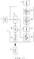
- FIG. 1 shows a block diagram of the entire configuration of the endoscope apparatus according to the first embodiment of the present invention.
- an endoscope apparatus 1 of the present embodiment comprises an electronic endoscope 2 (hereinafter referred to as an endoscope), an optical source apparatus 3, a video processor 4, an observation monitor 5 (hereinafter referred to as a monitor), a video printer 6, a key board 7, a mouse 8, USB memory 9, and a memory card (PC card) 10.
- the endoscope 2 may be inserted into a body cavity and is configured to capture images of the interior of the body cavity.
- the optical source apparatus 3 generates illumination light for observation.
- the video processor 4 performs signal processing of an image signal captured by the endoscope 2.
- the monitor 5 displays endoscope images.
- the video printer 6 prints out the endoscope images.
- the keyboard 7 and the mouse 8 perform operation instruction(s) and data input of the entire endoscope apparatus.
- the USB memory 9 is a storage medium that is removable from the video processor 4.
- the PC card 10 is a storage medium that is removable from the video processor 4.
- optical source apparatus 3 is integrated with the video processor 4; however, it can be a separate component.
- the endoscope 2 comprises an insertion unit 2A with an elongated shape that may be inserted into a body cavity, as well as an operation unit 2B that is provided at the posterior end of the insertion unit 2A.
- a light guide 16 for transmitting illumination light is inserted into the insertion unit 2A.
- a light guide connector 14 at the posterior end of the light guide 16 is connected in such a manner that it can be removed from the optical source apparatus 3.
- the light guide connector 14 transmits the illumination light supplied from the optical source apparatus 3.
- the transmitted illumination light lights the diseased part of the subject 2C and others parts in the body cavity via an end surface installed on an illumination window (not shown in the drawing) at a distal end 2a of the insertion unit 2A, and further via an illumination lens 17.
- the distal end 2a has an observation window (not shown in the drawing) that is located adjacent to the illumination window, wherein the observation window has an objective optical system 18 installed.
- An optical image of the illuminated subject 2C at the object optical system's 18 image position is produced.
- the imaging position has a CCD 19 that serves as a solid-state image sensing device and performs photoelectric conversions of the produced optical image(s).
- the CCD 19 is electrically connected to the video processor 4 via a signal line that is placed within the insertion unit 2A, a connector 11, a cable 12, and a connector 13.
- the image signal (an imaging signal), which is obtained from a photoelectric conversion by the CCD 19, is amplified by an amplifier 20 provided on the distal end 2a. Afterwards, the imaging signal is output to the video processor 4 via the signal line, the connector 11, the cable 12, and the connector 13.
- the operation unit 2B of an endoscope 2 has a CCD identification information unit 22 and a switch 21.
- the CCD identification information unit 22 stores model information (e.g. CCD identification information) and other information such as the electronic shutter speed of the endoscope 2.
- the switch 21 drives the CCD 19 and executes the observation mode.
- the optical source apparatus 3 comprises a lamp 23, a light adjuster unit 24, and a light adjuster control unit 25.
- the lamp 23 is a xenon lamp for radiating light.
- the light adjuster unit 24 is provided on an illumination light path of the lamp 23, comprises a plurality of optical filters, illumination light illumination light diaphragms, and rotating filters for adjusting the amount of illumination light.
- the light adjuster control unit 25 controls the light adjuster unit 24.
- the light adjuster control unit 25 controls the light adjuster unit 24 according to a control signal supplied from a video processor's 4 light adjuster control unit 30 (explained later) via the connector 13, the cable 12, the connector 11, and a signal line.
- the video processor 4 comprises a CCD driving unit 29, which generates a driving signal for driving the CCD 19.
- the video processor 4 is configured so that an image signal moves down in order corresponding to an A/D conversion circuit 26, a video pre-processing unit 27, an isolation unit 28, a video post-processing unit 31, a graphic display/superimposition unit 32, and a D/A conversion circuit 34.
- the A/D conversion circuit 26 converts the imaging signal output from the CCD 19 into a digital signal.
- the video pre-processing unit 27 preprocesses the image data output from the A/D converter circuit 26.
- the isolation unit 28 and the video post-processing unit 31 post-process the image data from the isolation unit 28.
- the graphic display/superimposition unit 32 combines and superimposes image data that is processed by the video post-processing unit 31 and image data stored on USB memory 9 or the memory card 10, which is an external storage medium that is explained later.
- the D/A conversion circuit 34 converts the digital signal output from the graphic display/superimposition unit 32 into an analog signal.
- the video processor 4 comprises a light adjuster control unit 30, a capture unit 3, a CPU 38, a bus 39, RAM 40, flash memory 41, an I/O port 42, a panel 43, a PCI (Peripheral Component Interconnect) bus bridge 44, a PCI bus 45, a USB (Universal Serial Bus) host controller 46, a PC card controller 48, and UART (Universal Asynchronous Receiver Transmitter) 50.
- the light adjuster control unit 30 controls the optical source apparatus's 3 light adjuster control unit 25.
- the capture unit 33 captures image data from the video post-processing unit 31 or image data from a storage medium such as the memory card 10.
- the CPU 38 performs various control operations throughout the entire apparatus.
- the bus 39 connects the CPU 38, the RAM 39, the flash memory 41, the I/O port 42, and the PCI bus bridge 44.
- the PCI bus 45 connects to the PCI bus bridge 44, the USB host controller 46, the PC card controller 48, the UART 50, the capture unit 33, and the graphic display/superimposition unit 32.
- the video processor 4 comprises a connector 35, a connector 36, a connecting terminal 37, a connecter unit 47, and a slot 49.
- the connector 35 is used to connect to the monitor 5.
- the connector 36 is used to connect to the video printer 6.
- the connecting terminal 37 is used to connect the UART 50 to the video printer 6.
- the connector unit 47 is used to connect the USB controller 46 to external USB equipment (such as the keyboard 7, the mouse 8, or the USB memory 9).
- the slot 49 is used to connect the PC card controller 48 to the memory card 10.
- Fig. 1 shows the video processor 4, according to the above configuration, wherein the A/D conversion circuit 26 converts the image signal obtained from the CCD 19, and outputs it to the video pre-processing unit 27.
- the video pre-processing unit 27 separates the color and isolates digitalized image data by using an isolation unit 28 and then outputs the data into a video post-processing unit 31.
- the video post-processing unit 31 performs video processing such as y conversion, edge enhancement, and expansion/reduction of supplied image data. Subsequently, the image data is superimposed with image data from the CPU circuit (which is explained later and includes an OSD (On-Screen Display) display image), or textual information from the graphic display/superimposition unit 32, and is output to the D/A conversion circuit 34.
- video processing such as y conversion, edge enhancement, and expansion/reduction of supplied image data.
- the image data is superimposed with image data from the CPU circuit (which is explained later and includes an OSD (On-Screen Display) display image), or textual information from the graphic display/superimposition unit 32, and is output to the D/A conversion circuit 34.
- OSD On-Screen Display
- the D/A conversion circuit 34 converts the supplied image data into analog.
- the analog image data is output to the monitor or the video printer 6 via the connector 35 or 36.
- an (endoscope) image is displayed according to the image signal supplied by the monitor 5, or an image according to the image signal supplied by the video printer 6 is printed out.
- the present embodiment includes an endoscope apparatus 1 (for driving a plurality of CCDs 19 with different driving conditions such as the number of pixels) that comprises a CCD identification information unit 22 in the endoscope's 2 operation unit.
- the video processor 4 can change the CCD's 19 driving conditions and the video post-processing unit's 31 processing parameters by using the identification information stored on the CCD identification information unit 22.
- the light adjuster unit 24 and the light adjuster control unit 25 are provided in the optical source apparatus 3 in order to maintain the optimal illumination conditions for the subject 2C (as explained above). Intensity of the illumination light is adjusted by these light adjuster unit 24 and the light adjuster control unit 25 controlled by the light adjuster control unit 30 in the video processor 4.
- the image data output from the video post-processing unit 31 is also supplied to the capture unit 33.
- the capture unit 33 is connected to the PCI bus 45.
- the capture unit 33 loads the endoscope image data and outputs it to the CPU circuit side (explained later) via the PCI bus 45.
- the CPU circuit comprises the CPU 38, the bus 39, the RAM 40, the flash memory 41, the I/O port 42, the PCI bus bridge 44, the PCI bus 45, the USB controller 46, the PC card controller 48, and the UART 50.
- the CPU circuit controls the internal video processor 4 and communicates with external equipment.
- the CPU 38 is connected to the RAM 40, the flash memory 41, and the I/O port 42 via the bus 39.
- the RAM 40 temporarily stores programs and data.
- the flash memory 41 holds programs and data when the power is OFF.
- the I/O port 42 controls the input/output signal from every circuit group.
- the panel 43 is connected to the I/O port 42.
- the panel 43 has a switch and LED for image quality adjustment.
- the panel 43 receives inputs from users through the switch, and controls the LED display through the LED.
- the PCI bus bridge 44 is connected to the CPU' s 38 bus 39.
- the PCI bus bridge 44 converts the CPU' s 38 bus 49 into the PCI bus 45, which is a general-purpose bus.
- the capture circuit 33, the USB controller 46, the PC card controller 48, and the UART 50 are connected to the PCI bus 45.
- the USB controller 46 is a circuit that connects to external USB equipment via a connector unit 47.
- the USB controller 46, the keyboard 7, the mouse's 8 HID (Human Interface Device), and the USB memory 9 are connected as USB equipment.
- the connector unit 47 comprises a connector 47a, a connector 47b, and a connector 47c.
- the connector 47a is for connecting the keyboard 7.
- the connector 47b is for connecting the mouse's 8 HID.
- the connector 47c is for connecting the USB memory 9.
- the PC card controller 48 is connected to the PC card slot 49, provided to the video processor 4, and controls the removable memory card 10 in the PC card slot 49.
- the UART 50 is a serial communication circuit with external equipment, and is used to remotely control the video printer 6.
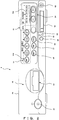
- Fig. 2 is a front view showing the exterior configuration of the video processor of Fig. 1 .
- the video processor 4 with this configuration has a main body 4A.
- the front face of the main body 4A has a front panel 4B.
- the left end of the front panel 4B in Fig. 2 has a power switch 51 for turning the video processor's 4 power on.
- An endoscope connection connector 52 (corresponding to connector 13 in Fig. 1 ) is provided proximally to the power switch 51.
- the endoscope connection connector 52 connects the connector (not shown in the drawing) to the basal end unit of the endoscope's 2 cable 12.
- the right side of the front panel includes a white balance switch 53.
- the white balance switch 53 adjusts the monitor's 5 white balance.
- the right side of the white balance 53 includes a light amount adjuster switch 54 and a LED 54a.
- the light amount adjuster switch 54 adjusts the amount of light from the optical source apparatus 3.
- the LED 54a displays the level when the amount of light is adjusted.
- Fig. 2 has an image selection switch 55 for selecting an input image near the center of the front panel 4B.
- the image selection switch 55 comprises a plurality of switches including SCOPE (endoscope 2), DV/VCR, PC (memory card 10), PRINTER (video printer 6), PinP (a picture-in-picture image displayed on the monitor 5) .
- SCOPE endoscope 2
- DV/VCR digital versatile disc recorder
- PC memory card 10
- PRINTER video printer 6
- PinP a picture-in-picture image displayed on the monitor 5
- each of the plurality of switches is an LED 55a that informs users of selected operations.
- a reset switch 56 Below the image selection switch 55 is a reset switch 56, an enhance (image enhancement) level switch 57, and a photometric mode selector switch 58.
- the reset switch 56 is a switch for, among other things, suspending and resetting the operation in execution.
- the enhance level switch 57 is pressed when the image displayed on a monitor needs to be enhanced.
- the photometric mode selector switch 58 is pressed when switching photometric modes.
- the front panel 4B of the video processor 4 has a PC card slot 62 (corresponding to the numerical reference 49 in Fig. 1 ).
- the right side of the PC card slot 62 includes an external image input connector 63 for connecting to the external image equipment.
- Fig. 2 includes a PC card stop switch 59 and an access display LED 60 that are proximate to the left side of the PC card slot 62.
- the PC card stop switch 59 is pressed down when the PC card slot 62 loads the memory card 10, and when the access operation needs to be stopped for any reason during the CPU's 38 access of the memory card 10.
- the CPU 38 recognizes that the switch is pressed down and controls the PC card controller 48 so as to stop access to the memory card 10.
- the access display LED 60 indicates when the CPU38 accesses the memory card 10 and informs users of the access.
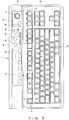
- Fig. 3 is a top view showing the exterior configuration of the keyboard in Fig. 1 .
- the keyboard 7 is connected to the video processor and, in accordance with the present embodiment, comprises a main body 7A.
- the main body 7A comprises a main key input unit 7B and a sub key input unit 7C that is placed above the main key input unit 7B.
- the main key input unit 7B primarily comprises an input key 70, a function key 71, and a VTR control key 74.
- the input key 70 performs normal input operations.
- a plurality of function keys 71 are placed above the input key 70.
- a PC card stop key (which operates in a similar manner to the PC card stop switch 59) 72 is assigned to one of the function keys 71.
- a PC card display key 73 is assigned to another one of the function keys 71.
- the VTR control key 74 is placed linearly next to the function keys 71.
- the PC card display key 73 is pressed when an image stored on the memory card 10 is displayed.
- the VTR control key 74 is a switch for controlling the VTR when the VTR (which is not shown in the drawing) is connected to the video processor 4,.
- the sub key input unit 7C comprises a pointer unit 75, a printer control key 78, a color tone key 79, a freeze key 81, a release key 82, and an inspection end key 83.
- the pointer unit 75 is located on the right side of the main body 7A and is configured to operate the mouse 8.
- the pointer unit 75 includes means for moving a cursor on the monitor 5 and for issuing execution instructions.
- This well known pointer unit 75 comprises a pointer 77 for moving a cursor and an execution button 76.
- the color tone key 79 is placed in the proximity of the printer control key 78.
- the printer control key 78 is placed to the left of the main body 7A and controls the video printer 6.
- a color tone LED 80 is placed next to the color tone key 79, and indicates the color tone level that is controlled by the color tone key 79. This allows users to recognize the adjusted color tone level at a glance.
- the freeze key 81 is placed next to the color tone key 79.
- the present embodiment of the endoscope apparatus 1 allows a user to add information, such as the names of patients (patient information) and additional information, to the endoscope image data by inputting data using the above configuration's keyboard 7.
- the endoscope apparatus 1 is able to store information, along with the image data, on the memory card 10 and on USB memory 9.
- the endoscope apparatus 1 can record information with the image data in the same manner as it records communications with external equipment, such as the video printer 6.
- the switch 21, which is provided in the operation unit 2B of the endoscope 2, the keyboard 7, or the panel's 43 switch, can issue the instruction for the record.
- the keyboard 7 has the PC card display key 73.
- the CPU 38 can read out image data from the memory card 10 or the USB memory 9 (which is a storage medium) by controlling the PC card controller 48 or the USB host controller 46, and display the image data and the information on the monitor via the graphic display/superimposition unit 32.
- the endoscope apparatus 1 of the present embodiment can read and reproduce images stored on the storage medium, such as the memory card 10, and can select a plurality of desired images from a set of images stored in a storage medium. These pluralities of desired images can then be displayed or printed out as a single image.
- the endoscope apparatus 1 can later add an annotation to a selected image, which may include patient information or additional information that is necessary for effective analyses and diagnoses.
- a function for selecting a plurality of desired images, displaying the images, printing them as a single image, and then adding an annotation to the selected images - which may include patient information or additional information necessary for effective analyses and diagnoses - is hereinafter referred to as an annotation function.
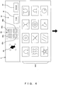
- Fig. 4 and Fig. 5 set forth the endoscope apparatus's 1 annotation function.
- the annotation function of the present embodiment is explained through Fig. 4 and Fig. 5 .
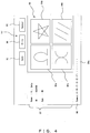
- Fig. 4 is an explanatory diagram showing operation procedures for selecting images and establishing annotation images.
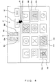
- Fig. 5 is an explanatory diagram showing a folder structure when the established annotation image in Fig. 4 is stored in a memory card.
- Fig. 4 shows the endoscope apparatus 1 of the present embodiment. If the annotation function is executed by pressing the PC card display key 73 in Fig. 3 , then the CPU controls the PC card controller 48 or the USB host controller 46 (as explained above), and reads out image data and information from the memory card 10 or the USB memory 9, which is a storage medium. Then the CPU 38 causes the monitor 5 to display an annotation screen 5A, which includes the plurality of images shown in Fig. 4 , via the graphic displaying/superimposition unit 32.
- Fig. 4 includes an annotation screen 5A comprising the annotation position designation unit 90, a "View” button 91, a “Cancel” button 92, a cursor 93, and an image display area 94.
- the annotation position designation unit 90 selects an annotation image.
- the "View” button 91 executes the image selected by the annotation position designation unit 90.
- the "Cancel” button 92 cancels the selection operation.
- the cursor 93 may select an operating image and an execution button at the annotation screen 5A.
- the image display area 94 displays a plurality of images.
- the annotation position designation unit 90 allows four images to be selected and comprises designation units 90a, 90b, 90c, and 90d according to the annotation position designations.
- the designation unit 90a selects and positions an image in the upper left portion of the screen.
- the designation unit 90b selects and positions an image in the upper right portion of the screen.
- the designation unit 90c selects and positions an image in the lower left portion of the screen and the designation unit 90d selects and positions an image in the lower right portion of the screen.
- the four designation units 90a-90d are colored in different colors: the designation unit 90a is red (shown with horizontal lines in the drawing), the designation unit 90b is blue (shown with vertical lines in the drawing), the designation unit 90c is green (shown with diagonal lines from the bottom left to the top right in the drawing), the designation unit 90d is yellow (shown with diagonal lines from the bottom right to the top left in the drawing).
- the designation unit 90a is red (shown with horizontal lines in the drawing)
- the designation unit 90b is blue (shown with vertical lines in the drawing)
- the designation unit 90c is green (shown with diagonal lines from the bottom left to the top right in the drawing)
- the designation unit 90d is yellow (shown with diagonal lines from the bottom right to the top left in the drawing).
- a user points the cursor 93 at the designation unit 90a by using the keyboard's 7 pointer unit 75 (see Fig. 3 ) or the mouse 8 (see Fig. 1 ).
- the video processor's 4 CPU 38 executes an image selection mode that is placed at a position corresponding to the designation unit 90a. In other words, as shown in the next annotation screen 5C, the CPU 38 displays an image selection cursor 90A on the image display area 94 by moving the cursor 63.
- a desired image is an image 94a
- the user points the cursor 93 at the image 94a
- the image 94a is designated by the image selection cursor 90A, and is selected when the execution button 76 (see Fig. 3 ) is pressed.
- the user points the cursor 93 at the designation unit 90b by using the keyboard's 7 pointer unit 75 (see Fig. 3 ) or the mouse 8 (see Fig. 1 ).
- the CPU 38 uses the same manner as above to execute the selection mode for the image placed at a position corresponding to the designation unit 90b. In other words, as shown in the annotation image 5D, as the cursor 63 moves, the CPU 38 causes the image selection cursor 90B to be displayed in the image display area 94.
- the desired image is an image 94b
- the user points the cursor 93 at the image 94b
- the image 94b is designated by the image selection cursor 90B, and is selected when the execution button 76 (see Fig. 3 ) is pressed.
- images for designation units 90c and 90d are selected in the same manner as the above image selection operation.
- the user completes the selection of the annotation images by pointing the cursor 93 to the "View" button 91 and pressing down the execution button 76 (see Fig. 3 ).
- the CPU 38 arranges images from the selected image data to a position designated by the designation units 90a-90d, generates an annotation screen 5J with the patient information and annotations being added, and displays the screen on the monitor 5.
- the annotation screen 5J comprises a display area 97, an annotation screen display area 98, an annotation display area 99, a "Save” button 95, a "Print” button 96, and a "Cancel” button 92.
- the display area 97 displays information (patient information) associated with the annotation image.
- the annotation image display area 98 comprises four images 94a-94d displayed at designated positions.
- the annotation display area 99 located at the bottom of the screen, is an area for displaying annotations such as comments on the annotation image.
- the "Save” button 95 executes an operation to store image data and annotations on the annotation screen 5J.
- the "Print” button 96 instructs the annotation screen 5J to be printed out.
- an annotation 99a such as a comment
- the present embodiment explains how four annotation images are selected by four designation units 90a-90d; however, the present embodiment is not limited to this case. It is possible for a user to set the desirable number of designation units to a different number, such as three.
- the CPU 38 supplies the video printer 6 with print outs of the image data and information on the annotation screen 5J by communicating with the UART 50.
- the CPU 38 controls the PC card controller 48, or the USB host controller 46, and stores the annotation screen's 5J image data and information to the memory card 10 or the USB memory 9.
- Fig. 5 shows a folder structure for when an annotation screen's image data and information is stored on the memory card 10.
- the video processor 4 in the present embodiment records the image data and annotation on the memory card 10 as hypertext according to the folder structure shown in Fig. 5 .
- the video processor 4 employs a well-known DCF (Design rule for Camera File system) digital camera image format, and records annotation(s).
- DCF Design rule for Camera File system
- the CPU 38 controls the memory card 10 and generates a first folder 10A including "DCIM” and "INDEX.HTM", a second folder 10B comprising image folders and annotation folders, and a third folder 10C, which is a subfolder of the second folder 10B, that stores every image file and every annotation file.
- a first folder 10A including "DCIM” and "INDEX.HTM”
- a second folder 10B comprising image folders and annotation folders
- a third folder 10C which is a subfolder of the second folder 10B, that stores every image file and every annotation file.
- the second folder 10B comprises image folders 10b1 and 10b2 for storing a plurality of image files for each diagnostic examination, and an annotation folder 10b3 for storing annotation image(s) (including annotations) generated by the annotation function.
- Image folders 10b1 and 10b2 are generated and added for every diagnostic examination.
- the annotation folder 10b3 is similarly generated and added for every execution of the annotation function.
- the folder "001AAAA” stores image files having a diagnostic examination such as "AAAA0001.JPG”(JPG compressed image), "AAAA0001.THM” (thumbnail image), or "AAAA0001.TIF” (TIFF uncompressed image) in the third folder 10C.
- the "999ZZZZZ" folder stores image files having one diagnostic examination such as "ZZAA0001.JPG"(JPG compressed image), "ZZAA0001.THM” (thumbnail image), or "ZZAA0001.TIF” (TIFF uncompressed image) in the third folder 10C.
- the "ANNO001” folder stores four selected images such as "AAAAO001.JPG” (JPG compressed image), “AAAA0002.JPG” (JPG compressed image), “AAAA0003.JPG” (JPG compressed image), "AAAA0004.JPG” (JPG compressed image), and an annotation file "ANNO0001.
- HTM HTTP file
- Data such as a list of all diagnostic examinations information, is stored as a HTML file ("INDEX.HTM") in the first folder 10A.
- usability can be improved by adding an annotation, as well as employing a DCF, to make it possible to reproduce and display image data and annotations stored on a memory card 10 by using a personal computer.
- the selected four image files are recorded as a file and the annotations are recorded as an HTML file; therefore, it is possible to display vivid image(s) and information without degradation of the image quality.
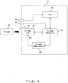
- Fig. 6 shows the second embodiment of the present invention wherein a block diagram shows an exterior configuration for the endoscope apparatus's video processor.
- the video processor's 4 PC card slot 49 has an eject button 49a for forcing the loaded memory card 10 in the PC card slot 49 to eject.
- a user can force the memory card 10 to eject by pressing the eject button 49a.
- Fig. 6 of the present embodiment shows the front panel 4B of a video processor 4 having an access stop switch 59 (which operates in the same manner as the PC card stop switch 59) and an access LED 60 provided near the PC card slot 49.
- the PC card stop key 72 can be the access stop switch 59.
- the access stop switch 59 is pressed when an access operation needs to be stopped for any reason during the CPU 38's access to the memory card 10.
- the CPU 38 recognizes the action and controls the CP card controller 48 so as to stop access (data read/write) to the memory card 10.
- the CPU 38 blocks power supply to the PC card slot 49 by controlling the PC card power 48a.
- the access LED 60 is controlled by the PC card controller 48, and displays whether the CPU 38 does, or does not, access the memory card 10.
- the PC card controller 48 lights the access LED 60.
- the light is turned off.
- the CPU 38 can control whether the data being written is destroyed, or whether to stop processing after the writing process is finished.
- the present embodiment it is possible to have the users recognize the access condition and the power supply condition at a glance by providing an access LED 60. As a result, it is possible to prevent accidental ejection by the eject cotton 49a, and it is also possible to prevent destruction of data on a memory card 10 and the memory card 10 itself.
- the present embodiment's access LED 60 can have a modified configuration as shown in Fig. 7 .
- Fig. 7 shows a modified example of the second embodiment's access LED, which is illustrated using a block diagram showing the configuration of the part containing the video processor 4.
- a green access LED 60a is connected via a resistance R1 between a power source control unit 48b, which is controlled by the PC card controller 48, and a PC card slot 49.
- a red access LED 60b is connected to the PC card controller 48 via a resistance R2. These two access LEDs, 60a and 60b, are incorporated by a single package and are provided to a certain position on the front panel 4B of the video processor 4.
- the PC card controller 48 controls the power supply control unit 48b, supplies a power supply signal, and lights the access LED 60a.
- the PC access controller 48 lights the access LED 60b by supplying an access display signal while lighting the access LED 60a.
- the PC card controller 48 controls whether both of the access LEDs 60a and 60b should be turned off.
- two access LEDs 60a and 60b are used; however, if a LED has a two-color display then a configuration with only one LED can be used.
- Fig. 8 is an explanatory diagram for explaining the third embodiment of the endoscope apparatus according to the present invention. It should be noted that in Fig. 8 , the same components as those used in the first embodiment are assigned with the same numerical reference, and the explanations are omitted.
- the endoscope apparatus 1 Generally it is desirable for the endoscope apparatus 1 to display endoscope images that are under examination in real time and also display endoscope images that are recorded on the memory card 10 at the same time so as to compare the images.
- the present embodiment's endoscope apparatus 1 has a configuration comprising a real-time image output connecter 35A and a PC card image output connecter 35B on a back face 4C (or a front panel 4B) of the video processor 4, and monitors 5 and 5X (not shown in the drawing) are connected to the respective connectors.
- the real-time connector 35A corresponds to the connecter 35 shown in Fig. 1 .
- the internal configuration of the video processor 4 is approximately the same as the internal configuration shown in Fig. 1 ; however, another system of graphic circuit units may be provided on the PCI bus 45 (see Fig. 1 .)
- the graphic displaying/superimposition unit 32 and the D/A converter circuit 34 are connected to the PCI bus 45 as shown in Fig. 1
- the PC card image output connecter 35A is connected to the D/A converter circuit 34.
- the newly provided monitor 5X is connected to the PC card image output connecter 35B.
- the monitor 5 displays the endoscope image under examination 100, and another monitor 5X displays the conventional endoscope image 101 stored on the memory card 10.
- the present embodiment can have a modified configuration as shown in Fig. 9 .
- Fig. 9 is an explanatory diagram that explains the modifications to the third embodiment.
- the present modifications have the same configuration as the video processor 4 shown in Fig. 1 with the PC card image output connecter 35B of the third embodiment removed.
- the endoscope image under examination 100 is displayed in real time and the endoscope image 101, which is recorded on the memory card 10, is displayed at the same time in a picture-in-picture display (PiP display); thereby allowing the images to be compared.
- a picture-in-picture display PiP display
- the video processor 4 performs a superimposing process via the graphic displaying/superimposition unit 32 and generates a PiP screen (see Fig. 9 .)
- the endoscope image data and the PC image data from the memory card are shown and, after D/A conversion, are output to the monitor 5 screen via the connector 35.
- the PiP screen shown in Fig. 9 is displayed on the monitor 5. Therefore, it is possible to display the endoscope image under examination 100 in real time, and the endoscope image 101 recorded on a memory card 10 at the same time; thereby, allowing a comparison of the images on a single monitor.
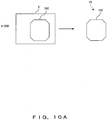
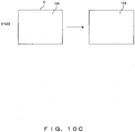
- Fig. 10 ( Fig. 10A , Fig. 10B , and Fig. 10C ) are diagrams explaining the fourth embodiment of the present invention's endoscope apparatus.
- Fig. 10A is an explanatory diagram showing an image to be recorded on an A-CCD.
- Fig. 10B is an explanatory diagram showing an image recorded on a B-CCD.
- Fig. 10C is an explanatory diagram showing an image recorded on a C-CCD. Note that in Fig. 10 , components that are the same as those in the first embodiment are assigned the same numerical references, and the explanations are omitted.
- a conventional endoscope apparatus records screens with an aspect ratio of 4:3 displayed on the observation screen of the monitor in a recording medium.
- a screen to be recorded has an octagonal endoscope image and a blank area other than the endoscope image. Consequently, with such a recording method, the blank area is recorded resulting in an increase in recording capacity.
- the blank area may display the patient ID or other information; however, it is not efficient to record a single patient ID on all images.
- the present embodiment only records endoscope images according to a CCD, without recording screens such as the blank area.
- the endoscope apparatus normally has different display areas on the endoscope screen in accordance with the number of CCD pixels mounted on the endoscope.
- the present embodiment's endoscope apparatus 1 distinguishes the video processor 4 that is connected to the endoscope 2 (CCD 19) on the basis of the identification information from the CCD identification information unit 22.
- the video processor's 4 CPU controls the video processor 4 that is connected to the endoscope 2 (CCD 19) and distinguishes the endoscope 2 (CCD 19) on the basis of the identification information from the CD identification information unit 22 and controls recording endoscope images on the memory card 10 on the basis of the masked area corresponding to each CCD 19 in advance.
- the CPU 38 determines that the endoscope's 2 CCD 19 is A-CCD, the size of the endoscope image 102 displayed on the observation screen is masked from the identification information, as shown in Fig. 10A .
- the CPU 38 controls the PC card controller 48 so as to record only the endoscope image 102 with the masked size on the memory card 10.
- the CPU 38 distinguishes that the endoscope's 2 CCD 19 is B-CCD, the size of the endoscope image 103 displayed on the observation screen is masked from the identification information, as shown in Fig. 10B .
- the CPU 38 controls the PC card controller 48 so as to record only the endoscope image 103 with the masked size on a memory card 10.
- the CPU 38 distinguishes that the endoscope's 2 CCD 19 is C-CCD, the size of the endoscope image 104 displayed on the observation screen has a full-screen mask, as shown in Fig. 10C .
- the CPU 38 controls the PC card controller 48 so as to record only the endoscope image 104 with the masked size (full screen) on a memory card 10.
- Fig. 11 and Fig. 12 show the fifth embodiment of the present invention's endoscope apparatus.
- Fig. 11 is a block diagram showing a major part of the endoscope apparatus's video processor.
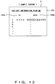
- Fig. 12 is a diagram showing a sample display of a monitor. Note that components in Fig. 11 and Fig. 12 , which are the same as the components in the first embodiment, are assigned with the same numerical references, and the explanations are omitted.
- the endoscope apparatus 1 of the first embodiment employs DCF as a recording format for recording on the memory card 10.
- DCF patient information and annotations are recorded under file names based on a certain standard and, when displayed, the information and the annotations are displayed by being run under the file name.
- the present embodiment's endoscope apparatus 1 displays information using the patient ID or the date included in the patient information rather than using the file names so as to be easily understandable to users.
- the video processor 4 further comprises a driver 48B, memory 41, a file name generation unit 48C, a file information acquisition unit 48D, and a video processing circuit unit 32A.
- the file name generation unit 48C is connected to the driver 48B (corresponding to the CCD driving unit 29 in Fig. 1 ) and the memory 41A (corresponding to RAM 40 or the flash memory 41 in Fig. 1 ) .
- the video processing circuit unit 32A (corresponding to the video post-processing unit 31 and the graphic displaying/superimposition unit 32 in Fig. 1 ) and the file information acquisition unit 48D are connected to the memory 41A, which performs various signal processing.
- the CPU 38 drives the driver 48B, reads out images, patient information, and annotations on the basis of each file name stored by DCF on the memory card 10 (as explained in the first embodiment), and loads the information on the file information acquisition unit 48D at the same time as temporarily storing the information on the memory 41A.
- the CPU 38 acquires file information to be displayed, such as patient ID and date, from the patient information and annotations provided by the file information acquisition init 48D.
- the CPU also processes generated display data by corresponding the acquired file information to the DCF file name via the video processing circuit unit 32A at a subsequent stage; thus causing the monitor 5 to display the information.
- Fig. 12 shows a sample display screen wherein information is displayed.
- the present embodiment's endoscope apparatus 1 displays a patient information loading screen 105 on the monitor 5.
- the patient information loading screen 105 displays a patient ID display unit 105a for displaying the patient ID, and a date display unit 105b for displaying date recording images, which responds to the patient ID display unit 105a.
- the CPU 38 can generate a new file name according to the file information acquired by the file information acquisition unit 48D regardless of the file name recorded by DCF. This information can be stored on the memory card in relation to the existing file name.
- Fig. 13 and Fig. 14 show that the present embodiment's endoscope apparatus 1 can be controlled so as to generate a file name according to the presence or absence of patient information.
- the modified example of the fifth embodiment is explained with reference to Fig. 13 and Fig. 14 .
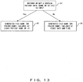
- Fig. 13 is an explanatory diagram showing the CPU' s 38 processing procedure.
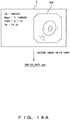
- Fig. 14 is a diagram showing the file names and the endoscope images generated as a result of the processing.
- the present modified example of an endoscope apparatus 1 uses the CPU 38 to determine whether or not prescribed patient information (patient data such as name and patient ID) is input in the determination processing step S1.
- patient data patient data such as name and patient ID
- the CPU 38 determines that patient information is input (i.e. proceeds to "Yes" at S1), the CPU 38 controls the file name generation unit 48C (see Fig. 11 ) and generates a name that contains at least the patient name or patient ID when processing the following step S2.
- An example of the resulting display is illustrated in Fig. 14A .
- the CPU 38 operates a control so as to generate a file name such as "ABC123_0002.JPG" on the basis of the patient information on the screen 106.
- the patient information is displayed with the endoscope images, as shown in Fig. 14A , and the name is stored on the memory card 10.
- the CPU 38 determines that patient information has not been input (i.e. proceeds to "No" at S1), the CPU 38 controls the file name generation unit 48C (see Fig. 11 ) and generates a name that contains at least the date and time when processing the following step S3.
- the CPU 38 operates a control so as to generate a file name such as "200406101824_0002.JPG" on the basis of the date and time information on the screen 107.
- the date and time are displayed with the endoscope images, as shown in Fig. 14B , and the name is stored on the memory card 10.
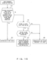
- Fig. 15 shows the sixth embodiment of the present invention's endoscope apparatus and is illustrated by a flowchart showing an example of the CPU controls in the endoscope apparatus.
- the components are the same as those in the fifth embodiment, are assigned the same numerical references, and the explanations are omitted.
- the present embodiment's endoscope apparatus can determine the presence or absence of the patient ID input, can generate an optical folder name based on the determination result, and can perform image recording on the memory card 10.
- the endoscope apparatus' s 1 CPU 38 uses step S10 to determine whether or not the patient ID is input after activation or during the activation and before insertion of the endoscope 2 into a body cavity and image recording operation.
- the CPU 38 When determining that a patient ID input has already been performed (i.e. proceeds to "Yes” at S10), the CPU 38 generates a folder based on the patient ID, stores the endoscope image and patient information (including annotations), and records data on the memory card 10 when processing the following step S11.
- the CPU 38 determines whether or not a resume (patient ID auto-save mode) function is ON in the determination processing step S12.
- a resume patient ID auto-save mode
- the process proceeds to step S15, and when the function is ON (i.e. proceeds to "Yes” in S10), the process proceeds to step S13.
- the CPU 38 determines whether or not the patient ID has already been input before activation.
- the CPU determines that the patient ID has already been input before activation (i.e. proceeds to "No" in S13)
- the CPU performs the process in the following step S14.
- processing step S14 and after setting a saving destination folder after recording images to a recording folder used at a previous time, the CPU 38 stores endoscope images and patient information (including annotations) in the recording folder and stores them on the memory card 10.
- processing step S15 if the resume function is OFF and the patient ID has not been input before the activation, then the CPU 38 may generate a new folder using the date or a temporary patient ID, and store the endoscope image and patient information (including annotations) on the memory card 10 in the newly generated folder.
- the saving destination folder when endoscope images and patient information (including annotations) are recorded on the memory card 10, it is possible to change the saving destination folder based on the presence or absence of the input of the patient ID at the activation. It is also possible to change the saving destination folder based on the presence or absence of the resume function. As a result, when reading out the recorded contents, it is easily recognizable to the users and therefore suitable for use.
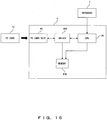
- the endoscope apparatus 1 of the first through sixth embodiments can have configurations, such as the one shown in Fig. 16 , by allowing patient lists to be recorded and loaded on the memory card 10. Patient information and patient lists generated on one endoscope apparatus can be shared by other endoscope apparatuses.
- the CPU 38 As shown in Fig. 16 , the CPU 38 generates a patient list and reads patient information using memory 41B (corresponding to RAM 40 or the flash memory 41 shown in Fig. 1 ), and stores the list in the memory card 10 by controlling the driver 48B (corresponding to the CCD driving unit 29 shown in Fig. 1 ) or by operating a reading control.
- memory 41B corresponding to RAM 40 or the flash memory 41 shown in Fig. 1
- the driver 48B corresponding to the CCD driving unit 29 shown in Fig. 1
- the present invention 's endoscope apparatus, there are advantages of selecting a plurality of images from a set of images stored on a recording medium, and displaying or recording the images as a single image with annotations.
Landscapes
- Health & Medical Sciences (AREA)
- Life Sciences & Earth Sciences (AREA)
- Surgery (AREA)
- Physics & Mathematics (AREA)
- Engineering & Computer Science (AREA)
- Optics & Photonics (AREA)
- Biomedical Technology (AREA)
- General Health & Medical Sciences (AREA)
- Pathology (AREA)
- Nuclear Medicine, Radiotherapy & Molecular Imaging (AREA)
- Biophysics (AREA)
- Heart & Thoracic Surgery (AREA)
- Medical Informatics (AREA)
- Molecular Biology (AREA)
- Animal Behavior & Ethology (AREA)
- Radiology & Medical Imaging (AREA)
- Public Health (AREA)
- Veterinary Medicine (AREA)
- Multimedia (AREA)
- Astronomy & Astrophysics (AREA)
- General Physics & Mathematics (AREA)
- Endoscopes (AREA)
- Instruments For Viewing The Inside Of Hollow Bodies (AREA)
Applications Claiming Priority (2)
| Application Number | Priority Date | Filing Date | Title |
|---|---|---|---|
| JP2005036971A JP2006218233A (ja) | 2005-02-14 | 2005-02-14 | 内視鏡装置 |
| PCT/JP2005/021713 WO2006085415A1 (ja) | 2005-02-14 | 2005-11-25 | 内視鏡装置 |
Publications (3)
| Publication Number | Publication Date |
|---|---|
| EP1849401A1 EP1849401A1 (en) | 2007-10-31 |
| EP1849401A4 EP1849401A4 (en) | 2010-09-22 |
| EP1849401B1 true EP1849401B1 (en) | 2016-12-28 |
Family
ID=36792993
Family Applications (1)
| Application Number | Title | Priority Date | Filing Date |
|---|---|---|---|
| EP05809579.5A Active EP1849401B1 (en) | 2005-02-14 | 2005-11-25 | Endoscope device |
Country Status (5)
| Country | Link |
|---|---|
| US (1) | US8537209B2 (ja) |
| EP (1) | EP1849401B1 (ja) |
| JP (1) | JP2006218233A (ja) |
| CN (2) | CN100473330C (ja) |
| WO (1) | WO2006085415A1 (ja) |
Families Citing this family (28)
| Publication number | Priority date | Publication date | Assignee | Title |
|---|---|---|---|---|
| JP5355846B2 (ja) * | 2006-05-08 | 2013-11-27 | オリンパスメディカルシステムズ株式会社 | 内視鏡用画像処理装置 |
| JP4981397B2 (ja) * | 2006-10-04 | 2012-07-18 | オリンパスメディカルシステムズ株式会社 | 医療用画像処理システム |
| JP2009265531A (ja) * | 2008-04-28 | 2009-11-12 | Olympus Corp | 内視鏡装置およびプログラム |
| JP5551765B2 (ja) * | 2010-04-01 | 2014-07-16 | オリンパス株式会社 | 内視鏡装置及び内視鏡装置用接続ユニット |
| CA2941578A1 (en) | 2010-09-08 | 2012-03-15 | Covidien Lp | Catheter with imaging assembly |
| US8606597B2 (en) * | 2011-02-24 | 2013-12-10 | Olympus Corporation | Endoscope inspection report creating apparatus, creating method of endoscope inspection report and storage medium |
| US9298351B2 (en) * | 2011-08-03 | 2016-03-29 | Olympus Corporation | Inspection image display apparatus, inspection image display method and storage medium |
| US9996681B2 (en) * | 2012-05-18 | 2018-06-12 | Carefusion 303, Inc. | Mobile device access for medical devices |
| JP5629023B2 (ja) * | 2012-05-30 | 2014-11-19 | オリンパスメディカルシステムズ株式会社 | 医療用3次元観察装置 |
| CN103513413B (zh) * | 2012-06-18 | 2017-05-24 | 奥林巴斯株式会社 | 内窥镜装置以及内窥镜图像的记录目的地文件夹变更方法 |
| WO2014035138A1 (ko) * | 2012-08-31 | 2014-03-06 | 부산대학교 산학협력단 | 의료 정보 처리 시스템 |
| USD735343S1 (en) | 2012-09-07 | 2015-07-28 | Covidien Lp | Console |
| US9517184B2 (en) | 2012-09-07 | 2016-12-13 | Covidien Lp | Feeding tube with insufflation device and related methods therefor |
| USD717340S1 (en) | 2012-09-07 | 2014-11-11 | Covidien Lp | Display screen with enteral feeding icon |
| US9198835B2 (en) | 2012-09-07 | 2015-12-01 | Covidien Lp | Catheter with imaging assembly with placement aid and related methods therefor |
| USD716841S1 (en) | 2012-09-07 | 2014-11-04 | Covidien Lp | Display screen with annotate file icon |
| US20140176661A1 (en) * | 2012-12-21 | 2014-06-26 | G. Anthony Reina | System and method for surgical telementoring and training with virtualized telestration and haptic holograms, including metadata tagging, encapsulation and saving multi-modal streaming medical imagery together with multi-dimensional [4-d] virtual mesh and multi-sensory annotation in standard file formats used for digital imaging and communications in medicine (dicom) |
| CN105519107B (zh) * | 2013-10-18 | 2018-06-19 | 奥林巴斯株式会社 | 图像信号输出装置以及图像信号收发系统 |
| WO2016017476A1 (ja) * | 2014-07-29 | 2016-02-04 | オリンパス株式会社 | 内視鏡のためのビデオプロセッサ及びそれを備えた内視鏡システム |
| JP6470092B2 (ja) * | 2015-04-15 | 2019-02-13 | オリンパス株式会社 | 電源管理システム |
| JPWO2017038321A1 (ja) * | 2015-09-03 | 2018-06-14 | オリンパス株式会社 | 内視鏡装置及び内視鏡装置の表示変更制御方法 |
| JP6717661B2 (ja) * | 2016-05-16 | 2020-07-01 | オリンパス株式会社 | 医療画像記録装置 |
| JP6929115B2 (ja) * | 2017-04-25 | 2021-09-01 | オリンパス株式会社 | 内視鏡装置、内視鏡システム及びレポート生成方法 |
| WO2018235389A1 (ja) * | 2017-06-20 | 2018-12-27 | オリンパス株式会社 | 医療表示装置 |
| JP7007139B2 (ja) * | 2017-09-20 | 2022-01-24 | オリンパス株式会社 | 内視鏡装置、内視鏡システム及び検査方法 |
| JP7289241B2 (ja) * | 2019-08-09 | 2023-06-09 | 富士フイルム株式会社 | ファイリング装置、ファイリング方法及びプログラム |
| CN111147756A (zh) * | 2020-01-03 | 2020-05-12 | 深圳术为科技有限公司 | 图像处理方法、图像处理系统及计算机可读存储介质 |
| USD986262S1 (en) * | 2021-07-01 | 2023-05-16 | Olympus Medical Systems Corporation | Display screen with graphical user interface |
Family Cites Families (24)
| Publication number | Priority date | Publication date | Assignee | Title |
|---|---|---|---|---|
| JP3012342B2 (ja) * | 1990-01-19 | 2000-02-21 | オリンパス光学工業株式会社 | 医療用画像表示装置 |
| JP3041015B2 (ja) * | 1990-04-18 | 2000-05-15 | オリンパス光学工業株式会社 | 内視鏡画像ファイルシステム |
| JPH0696170A (ja) | 1992-09-10 | 1994-04-08 | Olympus Optical Co Ltd | 内視鏡情報記録システム |
| US5412478A (en) * | 1992-09-30 | 1995-05-02 | Olympus Optical Co., Ltd. | Endoscope system which changes over switches in interlocking relation to each other within video processor and image display apparatus to perform display of endoscope image |
| JPH06327624A (ja) * | 1993-05-21 | 1994-11-29 | Olympus Optical Co Ltd | 電子内視鏡装置 |
| US6346940B1 (en) * | 1997-02-27 | 2002-02-12 | Kabushiki Kaisha Toshiba | Virtualized endoscope system |
| JPH1132983A (ja) | 1997-07-23 | 1999-02-09 | Olympus Optical Co Ltd | 内視鏡撮像装置 |
| JPH1189792A (ja) | 1997-09-24 | 1999-04-06 | Olympus Optical Co Ltd | 内視鏡システム |
| US6937267B1 (en) * | 1998-12-22 | 2005-08-30 | Pentax Corporation | Electronic endoscope |
| JP4223609B2 (ja) * | 1998-12-24 | 2009-02-12 | Hoya株式会社 | 内視鏡装置 |
| US6697101B1 (en) * | 1999-09-20 | 2004-02-24 | Pentax Corporation | Electronic endoscope |
| DE10059662B4 (de) * | 1999-12-03 | 2009-04-02 | Hoya Corp. | Elektronisches Endoskopsystem |
| US6678703B2 (en) * | 2000-06-22 | 2004-01-13 | Radvault, Inc. | Medical image management system and method |
| JP2003000536A (ja) * | 2001-06-26 | 2003-01-07 | Pentax Corp | 電子内視鏡装置 |
| JP3869698B2 (ja) * | 2001-10-23 | 2007-01-17 | ペンタックス株式会社 | 電子内視鏡装置 |
| US7226166B2 (en) * | 2001-11-13 | 2007-06-05 | Philadelphia Retina Endowment Fund | Optimizing the properties of electromagnetic energy in a medium using stochastic parallel perturbation gradient descent optimization adaptive optics |
| JP4067884B2 (ja) * | 2002-06-21 | 2008-03-26 | オリンパス株式会社 | 内視鏡装置 |
| US9936862B2 (en) | 2002-09-13 | 2018-04-10 | Karl Storz Imaging, Inc. | Video recording and image capture device |
| US7252633B2 (en) * | 2002-10-18 | 2007-08-07 | Olympus Corporation | Remote controllable endoscope system |
| JP2004174008A (ja) * | 2002-11-28 | 2004-06-24 | Olympus Corp | 内視鏡情報システム、内視鏡、及びプログラム |
| JP2004188026A (ja) | 2002-12-12 | 2004-07-08 | Olympus Corp | 情報処理装置 |
| JP2004208858A (ja) * | 2002-12-27 | 2004-07-29 | Toshiba Corp | 超音波診断装置及び超音波画像処理装置 |
| JP4356327B2 (ja) | 2003-01-31 | 2009-11-04 | コニカミノルタホールディングス株式会社 | 医用画像処理装置及び医用画像処理方法 |
| JP2005013573A (ja) * | 2003-06-27 | 2005-01-20 | Olympus Corp | 電子内視鏡システム |
-
2005
- 2005-02-14 JP JP2005036971A patent/JP2006218233A/ja active Pending
- 2005-11-25 WO PCT/JP2005/021713 patent/WO2006085415A1/ja active Application Filing
- 2005-11-25 EP EP05809579.5A patent/EP1849401B1/en active Active
- 2005-11-25 US US11/815,937 patent/US8537209B2/en active Active
-
2006
- 2006-02-14 CN CNB2006100077085A patent/CN100473330C/zh active Active
- 2006-02-14 CN CNU2006200017874U patent/CN200939124Y/zh not_active Expired - Lifetime
Also Published As
| Publication number | Publication date |
|---|---|
| CN1820698A (zh) | 2006-08-23 |
| EP1849401A4 (en) | 2010-09-22 |
| WO2006085415A1 (ja) | 2006-08-17 |
| JP2006218233A (ja) | 2006-08-24 |
| US8537209B2 (en) | 2013-09-17 |
| CN100473330C (zh) | 2009-04-01 |
| CN200939124Y (zh) | 2007-08-29 |
| EP1849401A1 (en) | 2007-10-31 |
| US20090303316A1 (en) | 2009-12-10 |
Similar Documents
| Publication | Publication Date | Title |
|---|---|---|
| EP1849401B1 (en) | Endoscope device | |
| US5583566A (en) | Combined medical image and data transmission with data storage, in which character/diagram information is transmitted with video data | |
| US5742339A (en) | Electronic still video camera | |
| JP2005013573A (ja) | 電子内視鏡システム | |
| JPH11266383A (ja) | デジタルカメラシステム | |
| JP2006271870A (ja) | 内視鏡用画像処理装置 | |
| WO2021073072A1 (zh) | 内窥镜摄像系统、摄像主机及其显示控制方法 | |
| US20080174687A1 (en) | Apparatus and method for photographing | |
| JP5030394B2 (ja) | 内視鏡画像表示装置及びその制御方法 | |
| JP4813178B2 (ja) | 内視鏡装置 | |
| CN214965293U (zh) | 一种4k医用内窥镜摄像系统 | |
| JP2001157200A (ja) | 内視鏡システム | |
| US7338438B2 (en) | Signal output apparatus of endoscope system | |
| JP2001275952A (ja) | 医療画像切替装置、および医療画像切替装置を備えた医療画像表示システム | |
| JP2001078174A (ja) | 画像処理装置 | |
| JP4827414B2 (ja) | 電子内視鏡システムとファイリングシステム | |
| JP2003265407A (ja) | 内視鏡装置 | |
| JP2001169159A (ja) | デジタルカメラおよびデジタルカメラシステム | |
| JP2006055350A (ja) | 内視鏡装置 | |
| JP2005049926A (ja) | デバイス機器 | |
| JP2005328201A (ja) | 顕微鏡デジタルカメラ | |
| JP2003339635A (ja) | 電子内視鏡装置 | |
| JPH09146012A (ja) | 電子内視鏡装置 | |
| JP2006334322A (ja) | 内視鏡システム | |
| JP4786831B2 (ja) | 内視鏡画像記録装置 |
Legal Events
| Date | Code | Title | Description |
|---|---|---|---|
| PUAI | Public reference made under article 153(3) epc to a published international application that has entered the european phase |
Free format text: ORIGINAL CODE: 0009012 |
|
| 17P | Request for examination filed |
Effective date: 20070904 |
|
| AK | Designated contracting states |
Kind code of ref document: A1 Designated state(s): DE FR GB |
|
| RIN1 | Information on inventor provided before grant (corrected) |
Inventor name: HASHIMOTO, SUSUMU OLYMPUS MEDICAL SYSTEMS CORP. Inventor name: NAKAGAWA, TAKEHIRO OLYMPUS MEDICAL SYSTEMS CORP. Inventor name: IWASAKI, TOMOKI OLYMPUS MEDICAL SYSTEMS CORP. Inventor name: SAITO, KATSUYUKI OLYMPUS MEDICAL SYSTEMS CORP. Inventor name: HIRAI, TSUTOMU OLYMPUS MEDICAL SYSTEMS CORP. |
|
| RBV | Designated contracting states (corrected) |
Designated state(s): DE FR GB |
|
| DAX | Request for extension of the european patent (deleted) | ||
| A4 | Supplementary search report drawn up and despatched |
Effective date: 20100820 |
|
| GRAP | Despatch of communication of intention to grant a patent |
Free format text: ORIGINAL CODE: EPIDOSNIGR1 |
|
| INTG | Intention to grant announced |
Effective date: 20160510 |
|
| RIN1 | Information on inventor provided before grant (corrected) |
Inventor name: NAKAGAWA, TAKEHIRO Inventor name: HIRAI, TSUTOMU Inventor name: HASHIMOTO, SUSUMU Inventor name: IWASAKI, TOMOKI Inventor name: SAITO, KATSUYUKI |
|
| GRAS | Grant fee paid |
Free format text: ORIGINAL CODE: EPIDOSNIGR3 |
|
| RAP1 | Party data changed (applicant data changed or rights of an application transferred) |
Owner name: OLYMPUS CORPORATION |
|
| RAP1 | Party data changed (applicant data changed or rights of an application transferred) |
Owner name: OLYMPUS CORPORATION |
|
| GRAA | (expected) grant |
Free format text: ORIGINAL CODE: 0009210 |
|
| AK | Designated contracting states |
Kind code of ref document: B1 Designated state(s): DE FR GB |
|
| REG | Reference to a national code |
Ref country code: GB Ref legal event code: FG4D |
|
| REG | Reference to a national code |
Ref country code: DE Ref legal event code: R096 Ref document number: 602005051027 Country of ref document: DE |
|
| REG | Reference to a national code |
Ref country code: DE Ref legal event code: R097 Ref document number: 602005051027 Country of ref document: DE |
|
| PLBE | No opposition filed within time limit |
Free format text: ORIGINAL CODE: 0009261 |
|
| STAA | Information on the status of an ep patent application or granted ep patent |
Free format text: STATUS: NO OPPOSITION FILED WITHIN TIME LIMIT |
|
| 26N | No opposition filed |
Effective date: 20170929 |
|
| GBPC | Gb: european patent ceased through non-payment of renewal fee |
Effective date: 20171125 |
|
| REG | Reference to a national code |
Ref country code: FR Ref legal event code: ST Effective date: 20180731 |
|
| PG25 | Lapsed in a contracting state [announced via postgrant information from national office to epo] |
Ref country code: FR Free format text: LAPSE BECAUSE OF NON-PAYMENT OF DUE FEES Effective date: 20171130 |
|
| PG25 | Lapsed in a contracting state [announced via postgrant information from national office to epo] |
Ref country code: GB Free format text: LAPSE BECAUSE OF NON-PAYMENT OF DUE FEES Effective date: 20171125 |
|
| P01 | Opt-out of the competence of the unified patent court (upc) registered |
Effective date: 20230528 |
|
| PGFP | Annual fee paid to national office [announced via postgrant information from national office to epo] |
Ref country code: DE Payment date: 20231121 Year of fee payment: 19 |