EP1832881A2 - Vorrichtung zum Schätzen einer Beschleunigung und Fahrzeug mit einer solchen Vorrichtung - Google Patents
Vorrichtung zum Schätzen einer Beschleunigung und Fahrzeug mit einer solchen Vorrichtung Download PDFInfo
- Publication number
- EP1832881A2 EP1832881A2 EP07004453A EP07004453A EP1832881A2 EP 1832881 A2 EP1832881 A2 EP 1832881A2 EP 07004453 A EP07004453 A EP 07004453A EP 07004453 A EP07004453 A EP 07004453A EP 1832881 A2 EP1832881 A2 EP 1832881A2
- Authority
- EP
- European Patent Office
- Prior art keywords
- acceleration
- vehicle
- offset
- acceleration sensor
- pitch angle
- Prior art date
- Legal status (The legal status is an assumption and is not a legal conclusion. Google has not performed a legal analysis and makes no representation as to the accuracy of the status listed.)
- Withdrawn
Links
Images


Classifications
-
- G—PHYSICS
- G01—MEASURING; TESTING
- G01P—MEASURING LINEAR OR ANGULAR SPEED, ACCELERATION, DECELERATION, OR SHOCK; INDICATING PRESENCE, ABSENCE, OR DIRECTION, OF MOVEMENT
- G01P15/00—Measuring acceleration; Measuring deceleration; Measuring shock, i.e. sudden change of acceleration
- G01P15/18—Measuring acceleration; Measuring deceleration; Measuring shock, i.e. sudden change of acceleration in two or more dimensions
-
- B—PERFORMING OPERATIONS; TRANSPORTING
- B60—VEHICLES IN GENERAL
- B60G—VEHICLE SUSPENSION ARRANGEMENTS
- B60G17/00—Resilient suspensions having means for adjusting the spring or vibration-damper characteristics, for regulating the distance between a supporting surface and a sprung part of vehicle or for locking suspension during use to meet varying vehicular or surface conditions, e.g. due to speed or load
- B60G17/015—Resilient suspensions having means for adjusting the spring or vibration-damper characteristics, for regulating the distance between a supporting surface and a sprung part of vehicle or for locking suspension during use to meet varying vehicular or surface conditions, e.g. due to speed or load the regulating means comprising electric or electronic elements
- B60G17/016—Resilient suspensions having means for adjusting the spring or vibration-damper characteristics, for regulating the distance between a supporting surface and a sprung part of vehicle or for locking suspension during use to meet varying vehicular or surface conditions, e.g. due to speed or load the regulating means comprising electric or electronic elements characterised by their responsiveness, when the vehicle is travelling, to specific motion, a specific condition, or driver input
- B60G17/0164—Resilient suspensions having means for adjusting the spring or vibration-damper characteristics, for regulating the distance between a supporting surface and a sprung part of vehicle or for locking suspension during use to meet varying vehicular or surface conditions, e.g. due to speed or load the regulating means comprising electric or electronic elements characterised by their responsiveness, when the vehicle is travelling, to specific motion, a specific condition, or driver input mainly during accelerating or braking
-
- B—PERFORMING OPERATIONS; TRANSPORTING
- B60—VEHICLES IN GENERAL
- B60G—VEHICLE SUSPENSION ARRANGEMENTS
- B60G17/00—Resilient suspensions having means for adjusting the spring or vibration-damper characteristics, for regulating the distance between a supporting surface and a sprung part of vehicle or for locking suspension during use to meet varying vehicular or surface conditions, e.g. due to speed or load
- B60G17/015—Resilient suspensions having means for adjusting the spring or vibration-damper characteristics, for regulating the distance between a supporting surface and a sprung part of vehicle or for locking suspension during use to meet varying vehicular or surface conditions, e.g. due to speed or load the regulating means comprising electric or electronic elements
- B60G17/019—Resilient suspensions having means for adjusting the spring or vibration-damper characteristics, for regulating the distance between a supporting surface and a sprung part of vehicle or for locking suspension during use to meet varying vehicular or surface conditions, e.g. due to speed or load the regulating means comprising electric or electronic elements characterised by the type of sensor or the arrangement thereof
- B60G17/01908—Acceleration or inclination sensors
-
- B—PERFORMING OPERATIONS; TRANSPORTING
- B60—VEHICLES IN GENERAL
- B60T—VEHICLE BRAKE CONTROL SYSTEMS OR PARTS THEREOF; BRAKE CONTROL SYSTEMS OR PARTS THEREOF, IN GENERAL; ARRANGEMENT OF BRAKING ELEMENTS ON VEHICLES IN GENERAL; PORTABLE DEVICES FOR PREVENTING UNWANTED MOVEMENT OF VEHICLES; VEHICLE MODIFICATIONS TO FACILITATE COOLING OF BRAKES
- B60T8/00—Arrangements for adjusting wheel-braking force to meet varying vehicular or ground-surface conditions, e.g. limiting or varying distribution of braking force
- B60T8/17—Using electrical or electronic regulation means to control braking
- B60T8/1701—Braking or traction control means specially adapted for particular types of vehicles
- B60T8/1706—Braking or traction control means specially adapted for particular types of vehicles for single-track vehicles, e.g. motorcycles
-
- B—PERFORMING OPERATIONS; TRANSPORTING
- B60—VEHICLES IN GENERAL
- B60T—VEHICLE BRAKE CONTROL SYSTEMS OR PARTS THEREOF; BRAKE CONTROL SYSTEMS OR PARTS THEREOF, IN GENERAL; ARRANGEMENT OF BRAKING ELEMENTS ON VEHICLES IN GENERAL; PORTABLE DEVICES FOR PREVENTING UNWANTED MOVEMENT OF VEHICLES; VEHICLE MODIFICATIONS TO FACILITATE COOLING OF BRAKES
- B60T8/00—Arrangements for adjusting wheel-braking force to meet varying vehicular or ground-surface conditions, e.g. limiting or varying distribution of braking force
- B60T8/17—Using electrical or electronic regulation means to control braking
- B60T8/172—Determining control parameters used in the regulation, e.g. by calculations involving measured or detected parameters
-
- G—PHYSICS
- G01—MEASURING; TESTING
- G01P—MEASURING LINEAR OR ANGULAR SPEED, ACCELERATION, DECELERATION, OR SHOCK; INDICATING PRESENCE, ABSENCE, OR DIRECTION, OF MOVEMENT
- G01P15/00—Measuring acceleration; Measuring deceleration; Measuring shock, i.e. sudden change of acceleration
-
- B—PERFORMING OPERATIONS; TRANSPORTING
- B60—VEHICLES IN GENERAL
- B60G—VEHICLE SUSPENSION ARRANGEMENTS
- B60G2300/00—Indexing codes relating to the type of vehicle
- B60G2300/12—Cycles; Motorcycles
-
- B—PERFORMING OPERATIONS; TRANSPORTING
- B60—VEHICLES IN GENERAL
- B60G—VEHICLE SUSPENSION ARRANGEMENTS
- B60G2400/00—Indexing codes relating to detected, measured or calculated conditions or factors
- B60G2400/10—Acceleration; Deceleration
- B60G2400/102—Acceleration; Deceleration vertical
-
- B—PERFORMING OPERATIONS; TRANSPORTING
- B60—VEHICLES IN GENERAL
- B60G—VEHICLE SUSPENSION ARRANGEMENTS
- B60G2400/00—Indexing codes relating to detected, measured or calculated conditions or factors
- B60G2400/10—Acceleration; Deceleration
- B60G2400/106—Acceleration; Deceleration longitudinal with regard to vehicle, e.g. braking
-
- B—PERFORMING OPERATIONS; TRANSPORTING
- B60—VEHICLES IN GENERAL
- B60G—VEHICLE SUSPENSION ARRANGEMENTS
- B60G2400/00—Indexing codes relating to detected, measured or calculated conditions or factors
- B60G2400/20—Speed
- B60G2400/204—Vehicle speed
-
- B—PERFORMING OPERATIONS; TRANSPORTING
- B60—VEHICLES IN GENERAL
- B60G—VEHICLE SUSPENSION ARRANGEMENTS
- B60G2400/00—Indexing codes relating to detected, measured or calculated conditions or factors
- B60G2400/20—Speed
- B60G2400/208—Speed of wheel rotation
-
- B—PERFORMING OPERATIONS; TRANSPORTING
- B60—VEHICLES IN GENERAL
- B60G—VEHICLE SUSPENSION ARRANGEMENTS
- B60G2600/00—Indexing codes relating to particular elements, systems or processes used on suspension systems or suspension control systems
- B60G2600/18—Automatic control means
- B60G2600/187—Digital Controller Details and Signal Treatment
- B60G2600/1871—Optimal control; Kalman Filters
-
- B—PERFORMING OPERATIONS; TRANSPORTING
- B60—VEHICLES IN GENERAL
- B60G—VEHICLE SUSPENSION ARRANGEMENTS
- B60G2800/00—Indexing codes relating to the type of movement or to the condition of the vehicle and to the end result to be achieved by the control action
- B60G2800/70—Estimating or calculating vehicle parameters or state variables
- B60G2800/702—Improving accuracy of a sensor signal
Definitions
- the present invention relates to an acceleration estimation device that estimates vehicle acceleration, and a vehicle including the same.
- the traveling speed of a vehicle can be calculated on the basis of the rotational speeds of its wheels.
- the wheels When the vehicle is rapidly accelerated, however, the wheels may be rotated while slipping on a road surface. When the vehicle is rapidly decelerated (braked), the wheels may be caused to slide on the road surface. In such a case, the speed of the vehicle that can be calculated from the rotational speed of the wheels does not coincide with the actual traveling speed of the vehicle.
- the acceleration of the vehicle is detected using an acceleration sensor, and the detected acceleration is integrated to calculate the speed of the vehicle.
- the vehicle body When the vehicle is rapidly accelerated or decelerated, however, the vehicle body is inclined up and down in a traveling direction by pitching of the vehicle body. That is, the front of the vehicle body rises at the time of the rapid acceleration, and lowers at the time of the rapid deceleration.
- the forward-and-backward acceleration of the vehicle that is detected by the acceleration sensor does not accurately coincide with an acceleration in a traveling direction of the vehicle.
- JP 10-104259 A discloses a vehicle longitudinal acceleration estimating device that removes an unnecessary component of an acceleration sensor for detecting a longitudinal acceleration to calculate an estimated value of the longitudinal acceleration.
- the change in an output voltage of the acceleration sensor is frequency-analyzed and is classified into changes due to DC offset, changes due to temperature drift, changes due to road conditions, changes due to acceleration/deceleration of the vehicle, and changes due to pitching of the vehicle body.
- a Karman filter is used to extract only a variable component having a higher frequency than a particular frequency from a detected value of the longitudinal acceleration by the acceleration sensor.
- JP 8-268257 A discloses an actual speed estimator that estimates an actual vehicle speed of a vehicle.
- a coefficient of rolling rigidity and a coefficient of pitching rigidity are defined to correct an output of a crosswise acceleration sensor and an output of a lengthwise acceleration sensor using the coefficient of rolling rigidity and the coefficient of pitching rigidity.
- preferred embodiments of the present invention provide an acceleration estimation device that can accurately estimate an acceleration in a traveling direction of a vehicle, and a vehicle including the same.
- an acceleration estimation device for estimating accelerations of a vehicle includes a first acceleration sensor that is provided in the vehicle and detects the acceleration in the forward-and-backward direction of the vehicle; a second acceleration sensor that is provided in the vehicle and detects the acceleration in the up-and-down direction of the vehicle; a pitch angle estimator that estimates the pitch angle of the vehicle on the basis of the relationship between a detected value in the first acceleration sensor and a detected value in the second acceleration sensor; and an acceleration calculator that calculates the acceleration in a traveling direction of the vehicle that is perpendicular or substantially perpendicular to a direction of gravity, on the basis of an estimated value of the pitch angle obtained by the pitch angle estimator, the detected value in the first acceleration sensor, and the detected value in the second acceleration sensor.
- the first acceleration sensor and the second acceleration sensor are provided in the vehicle.
- the first acceleration sensor detects the acceleration in the forward-and-backward direction of the vehicle
- the second acceleration sensor detects the acceleration in the up-and-down direction of the vehicle.
- the pitch angle estimator estimates the pitch angle of the vehicle on the basis of the relationship between the detected value in the first acceleration sensor and the detected value in the second acceleration sensor.
- the acceleration in the traveling direction of the vehicle is calculated on the basis of the estimated value of the pitch angle, the detected value in the first acceleration sensor, and the detected value in the second acceleration sensor.
- the pitch angle due to arbitrary pitching of the vehicle can be estimated with high accuracy. This allows the acceleration in the traveling direction of the vehicle to be detected with high accuracy.
- the acceleration estimation device may further include a speed calculator that integrates a calculated value of the acceleration in the traveling direction obtained by the acceleration calculator, to calculate a speed in the traveling direction.
- the speed in the traveling direction of the vehicle can be detected with high accuracy.
- the pitch angle estimator may include a first Karman filter that estimates the pitch angle of the vehicle using the relationship among the acceleration in the traveling direction of the vehicle that is perpendicular or substantially perpendicular to the direction of gravity, the acceleration in a vertical direction parallel or substantially parallel to the direction of gravity, the detected value in the first acceleration sensor, and the detected value in the second acceleration sensor, and the pitch angle of the vehicle.
- the first Karman filter estimates the pitch angle of the vehicle. Even when the detected value of the acceleration in the forward-and-backward direction and the detected value of the acceleration in the up-and-down direction of the vehicle are affected by gravity due to pitching having an arbitrary frequency, it is possible to detect the pitch angle of the vehicle with high accuracy.
- the acceleration estimation device may further include an offset estimator that estimates offset in the first acceleration sensor and offset in the second acceleration sensor when the vehicle is at a substantially constant speed, and a corrector that corrects the detected value in the first acceleration sensor and the detected value in the second acceleration sensor on the basis of an estimated value of the offset in the first acceleration sensor and an estimated value of the offset in the second acceleration sensor that are obtained by the offset estimator when the vehicle is accelerated or decelerated, and the pitch angle estimator may estimate the pitch angle of the vehicle on the basis of the relationship between the detected value in the first acceleration sensor and the detected value in the second acceleration sensor that are corrected by the corrector when the vehicle is accelerated or decelerated.
- an offset estimator that estimates offset in the first acceleration sensor and offset in the second acceleration sensor when the vehicle is at a substantially constant speed
- a corrector that corrects the detected value in the first acceleration sensor and the detected value in the second acceleration sensor on the basis of an estimated value of the offset in the first acceleration sensor and an estimated value of the offset in the second acceleration sensor that are obtained by
- the time when the vehicle is at a substantially constant speed refers to the time when the vehicle is stopped and the time when the rate of change in the traveling speed of the vehicle is not more than a predetermined threshold value.
- the threshold value is in a range of about -0.2 m/s 2 to about +0.2 m/s 2 , for example.
- the offset estimator estimates the offset in the first acceleration sensor and the offset in the second acceleration sensor.
- the offset in the first acceleration sensor and the offset in the second acceleration sensor preferably are not changed in a short time period.
- the corrector corrects the detected value in the first acceleration sensor and the detected value in the second acceleration sensor on the basis of the estimated value of the offset in the first acceleration sensor and the estimated value of the offset in the second acceleration sensor that are obtained when the vehicle is at a substantially constant speed.
- the pitch angle of the vehicle is estimated on the basis of the detected value in the first acceleration sensor and the detected value in the second acceleration sensor that are corrected. This allows the pitch angle of the vehicle to be detected with higher accuracy.
- the acceleration estimation device may further include a wheel speed detector that detects a wheel speed of the vehicle
- the offset estimator may include a second Karman filter that estimates the offset in the first acceleration sensor and the offset in the second acceleration sensor using the relationship among the acceleration in the traveling direction, the acceleration in the vertical direction, the detected value in the first acceleration sensor, the detected value in the second acceleration sensor, the speed in the traveling direction, the speed in the vertical direction, the speed of the vehicle obtained from the detected value in the wheel speed detector, and the pitch angle of the vehicle.
- the second Karman filter estimates the offset in the first acceleration sensor and the offset in the second acceleration sensor. Even when the detected value of the acceleration in the forward-and-backward direction and the detected value of the acceleration in the up-and-down direction are affected by gravity due to pitching having an arbitrary frequency, therefore, it is possible to more accurately estimate the offset in the first acceleration sensor and the offset in the second acceleration sensor. As a result, the pitch angle of the vehicle can be detected with higher accuracy.
- An observed disturbance applied to the first acceleration sensor and the second acceleration sensor is removed in the second Karman filter. This prevents a control system controlled on the basis of the acceleration in the traveling direction of the vehicle from being unstable due to the observed disturbance.
- the offset estimator may determine that the vehicle is in a substantially constant speed state when the rate of change in the wheel speed detected by the wheel speed detector is not more than a predetermined threshold value, and the pitch angle estimator may determine that the vehicle is accelerated or decelerated when the rate of change in the wheel speed detected by the wheel speed detector is higher than the threshold value.
- the offset estimator estimates the offset in the first acceleration sensor and the offset in the second acceleration sensor. Further, it is determined that the vehicle is accelerated or decelerated when the rate of change in the wheel speed is higher than the threshold value.
- the pitch angle estimator estimates the pitch angle of the vehicle.
- the offset in the first acceleration sensor and the offset in the second acceleration sensor can be detected with high accuracy.
- the pitch angle of the vehicle can be detected with higher accuracy when the vehicle is accelerated or decelerated.
- a vehicle includes a vehicle body, a wheel provided on the vehicle body, an acceleration estimation device that is provided on the vehicle body, and a controller, wherein the acceleration estimation device includes a first acceleration sensor that is provided on the vehicle and detects the acceleration in the forward-and-backward direction of the vehicle; a second acceleration sensor that is provided on the vehicle and detects the acceleration in the up-and-down direction of the vehicle; a pitch angle estimator that estimates the pitch angle of the vehicle on the basis of the relationship between a detected value in the first acceleration sensor and a detected value in the second acceleration sensor; and an acceleration calculator that calculates the acceleration in a traveling direction of the vehicle that is perpendicular or substantially perpendicular to a direction of gravity on the basis of an estimated value of the pitch angle obtained by the pitch angle estimator, the detected value in the first acceleration sensor, and the detected value in the second acceleration sensor, the controller controls the rotation of the wheel on the basis of the acceleration in the traveling direction obtained by the acceleration estimation device.
- the acceleration estimation device includes a first acceleration sensor that is provided on
- the acceleration estimation device estimates the pitch angle of the vehicle on the basis of the relationship between the detected value in the first acceleration sensor and the detected value in the second acceleration sensor.
- the acceleration in the traveling direction of the vehicle is calculated on the basis of the estimated value of the pitch angle, the detected value in the first acceleration sensor, and the detected value in the second acceleration sensor. This allows the acceleration in the traveling direction of the vehicle to be detected with high accuracy.
- the controller controls the rotation of the wheel on the basis of the acceleration in the traveling direction of the vehicle that is obtained by the acceleration estimation device.
- the pitch angle estimator estimates the pitch angle of the vehicle on the basis of the relationship between the detected value in the first acceleration sensor and the detected value in the second acceleration sensor.
- the acceleration in the traveling direction of the vehicle is calculated on the basis of the estimated value of the pitch angle, the detected value in the first acceleration sensor, and the detected value in the second acceleration sensor.
- the pitch angle due to arbitrary pitching of the vehicle can be estimated with high accuracy. This allows the acceleration in the traveling direction of the vehicle to be detected with high accuracy.
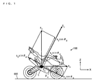
- Fig. 1 is a diagram showing the relationship of accelerations received by an acceleration sensor at the time of deceleration.
- Fig. 2 is a diagram showing the schematic configuration of the overall motorcycle according to a preferred embodiment of the present invention.
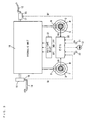
- Fig. 3 is a schematic view showing a hydraulic system and an electrical system of an ABS.
- Fig. 4 is a block diagram showing the configuration of a vehicle speed estimator.
- Fig. 5 is a diagram for explaining the relationship between an operation of estimating x-direction acceleration offset and z-direction acceleration offset in the vehicle speed estimator and the change in wheel speed.
- Fig. 6 is a flow chart showing the operations of the vehicle speed estimator.
- Fig. 7 is a block diagram showing the configuration of an ABS signal processor.
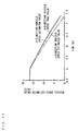
- Fig. 8 is a diagram showing the relationship between an acceleration offset true value and an acceleration offset estimated error.
- Fig. 9 is a diagram showing the change with time of an acceleration offset estimated value in the process of estimating acceleration offset.
- Fig. 10 is a diagram showing the results of estimation of X-direction acceleration.
- Fig. 11 is a diagram showing the results of estimation of a vehicle speed.
- Fig. 1 is a diagram showing the relationship of accelerations received by an acceleration sensor at the time of deceleration.
- a motorcycle 100 when a motorcycle 100 is decelerated by a front-wheel brake, a front suspension contracts, and a rear suspension expands. Therefore, the motorcycle 100 is inclined forward in its traveling direction.
- a coordinate system fixed to the ground below the motorcycle 100 is taken as a ground coordinate system, and a coordinate system fixed to the acceleration sensor attached to the motorcycle 100 is taken as a sensor coordinate system.
- a traveling direction of the motorcycle 100 (a direction perpendicular or substantially perpendicular to gravity) on a horizontal ground surface 600 is defined as an X-direction
- a vertical direction (a direction of gravity) is defined as a Z-direction. Consequently, the X-direction and the Z-direction on the ground coordinate system are not changed irrespective of the posture of the motorcycle 100.
- a direction of the horizontal axis of the motorcycle 100 (a forward-and-backward direction of a vehicle body 1) in a case where the motorcycle 100 is in a horizontal state is defined as an x-direction
- a direction perpendicular or substantially perpendicular to the horizontal axis of the motorcycle 100 (an up-and-down direction of the vehicle body 1) is defined as a z-direction. Consequently, the x-direction and the z-direction on the sensor coordinate system are inclined to the X-direction and the Z-direction on the ground coordinate system by the posture of the motorcycle 100.
- the X-direction on the ground coordinate system is merely referred to as an X-direction or a traveling direction
- the Z-direction on the ground coordinate system is referred to as a Z-direction or a vertical direction.
- an acceleration G x in the x-direction and an acceleration G z in the z-direction on the sensor coordinate system are respectively expressed by the following equations using an acceleration a x in the X-direction and an acceleration a z in the Z-direction on the ground coordinate system:
- G x a x ⁇ cos ⁇ p - a z ⁇ sin ⁇ p
- G z a x ⁇ sin ⁇ p + a z ⁇ cos ⁇ p
- ⁇ P denotes the pitch angle of the vehicle body 1.
- the motorcycle 100 in the present preferred embodiment is provided with an x-direction acceleration sensor for detecting the acceleration G x in the x-direction of the vehicle body 1 and a z-direction acceleration sensor for detecting the acceleration G z in the z-direction.
- the acceleration a x in the X-direction and the acceleration a z in the Z-direction on the ground coordinate system of the motorcycle 100 can be measured by detecting the acceleration G x in the x-direction using the x-direction acceleration sensor, detecting the acceleration G z in the z-direction using the z-direction acceleration sensor, and determining the pitch angle ⁇ P .
- the offset in the acceleration sensor refers to a value obtained by expressing a difference between a nominal value of an output voltage of the acceleration sensor at an acceleration of 0 m/s 2 and a value of an actual output voltage of the acceleration sensor in terms of unit of acceleration (m/s 2 ).
- offset in the x-direction acceleration sensor is referred to as x-direction acceleration offset
- offset in the z-direction acceleration sensor is referred to as z-direction acceleration offset
- the x-direction acceleration offset and the z-direction acceleration offset are estimated using an extended Karman filter, described later, when the motorcycle 100 is at a substantially constant speed.
- the time when the motorcycle 100 is at a substantially constant speed includes the time when the motorcycle 100 is stopped and the time when the rate of change in the traveling speed of the motorcycle 100 is not more than a predetermined threshold value.
- the time when the motorcycle 100 is traveling at a constant speed and the time when the rate of change in the traveling speed is not more than a threshold value are merely referred to as the time when the motorcycle 100 is traveling at a constant speed.
- the acceleration G x in the x-direction and the acceleration G z in the z-direction are corrected on the basis of respective estimated values of the x-direction acceleration offset and the z-direction acceleration offset, and the pitch angle ⁇ P of the vehicle body 1 is estimated on the basis of respective corrected values of the acceleration G x in the x-direction and the acceleration G z in the z-direction.
- the acceleration in the X-direction and the acceleration in the Z-direction of the motorcycle 100 are calculated using an estimated value of the pitch angle ⁇ P .
- the acceleration in the X-direction is integrated to calculate the speed in the X-direction of the motorcycle 100.
- Fig. 2 is a diagram showing the schematic configuration of the motorcycle 100 according to the present preferred embodiment.
- An ABS (Anti-Lock Brake System), described later, is preferably included in the motorcycle 100.
- a front wheel 2 is attached to the front of the vehicle body 1 of the motorcycle 100, and a rear wheel 3 is attached to the rear of the vehicle body 1.
- a sensor rotor 4 that rotates with the front wheel 2 is provided at the center of the front wheel 2.
- a front-wheel speed sensor 5 for detecting the rotational speed of the front wheel 2 is attached to the sensor rotor 4. Further, there is provided a front brake caliper 6 that is brought into contact with a brake disk of the front wheel 2 for braking the front wheel 2.
- a sensor rotor 7 that rotates with the rear wheel 3 is provided at the center of the rear wheel 3.
- a rear-wheel speed sensor 8 for detecting the rotational speed of the rear wheel 3 is attached to the sensor rotor 7. Further, there is provided a rear brake caliper 9 that is brought into contact with a brake disk of the rear wheel 3 for braking the rear wheel 3.
- a handle 11 is arranged so as to be swingable right and left at the top on the front side of the vehicle body 1.
- the handle 11 is provided with a front brake lever 12 and a warning lamp 13.
- a hydraulic unit 10 is provided at the center of the vehicle body 1.
- a rear brake pedal 14 is provided below the center of the vehicle body 1.
- An x-direction acceleration sensor 21 and a z-direction acceleration sensor 22 are attached to a position at the center of gravity of the vehicle body 1.
- a two-axis acceleration sensor or a three-axis acceleration sensor for use in detection of inclination, an impact of air bags, a drop of hard disks, etc. can be used.
- ECU electronice control unit
- fail-safe relay 31 are provided at the rear of the vehicle body 1.
- Fig. 3 is a schematic view showing a hydraulic system and an electrical system of the ABS.
- a master cylinder 15 is connected to the front brake lever 12, and the master cylinder 15 is connected to the hydraulic unit 10.
- the master cylinder 15 is provided with a brake switch 17.
- a master cylinder 16 is connected to the rear brake pedal 14, and the master cylinder 16 is connected to the hydraulic unit 10.
- the master cylinder 16 is provided with a brake switch 18.
- the master cylinder 15 raises the pressure of hydraulic fluid supplied to the front brake caliper 6 from the hydraulic unit 10. This causes the front brake caliper 6 to be driven to brake the front wheel 2.
- the brake switch 17 is turned on so that a front-wheel brake signal Bf is fed to the ECU 30.
- the master cylinder 16 raises the pressure of hydraulic fluid supplied to the rear brake caliper 9 from the hydraulic unit 10. This causes the rear brake caliper 9 to be driven to brake the rear wheel 3.
- the brake switch 18 is turned on so that a rear-wheel brake signal Br is fed to the ECU 30.
- a front-wheel speed signal Rf representing the rotational speed of the front wheel 2 is fed to the ECU 30 from the front-wheel speed sensor 5 provided in the sensor rotor 4 in the front wheel 2.
- a rear-wheel speed signal Rr representing the rotational speed of the rear wheel 3 is fed to the ECU 30 from the rear-wheel speed sensor 8 provided in the sensor rotor 7 in the rear wheel 3.
- the rotational speed of the front wheel 2 is referred to as a front wheel speed
- the rotational speed of the rear wheel 3 is referred to as a rear wheel speed.
- An x-direction acceleration signal Ax representing x-direction acceleration is fed to the ECU 30 from the x-direction acceleration sensor 21.
- a z-direction acceleration signal Az representing z-direction acceleration is fed to the ECU 30 from the z-direction acceleration sensor 22.
- the ECU 30 outputs a motor driving signal MD for driving a motor for a hydraulic pump within the hydraulic unit 10 to the hydraulic unit 10 through the fail-safe relay 31 in response to the front-wheel brake signal Bf or the rear-wheel brake signal Br.
- the ECU 30 outputs a reduced pressure signal FP for the front wheels and a reduced pressure signal RP for the rear wheels to the hydraulic unit 10 through the fail-safe relay 31 on the basis of the front-wheel speed signal Rf, the rear-wheel speed signal Rr, the x-direction acceleration signal Ax, and the z-direction acceleration signal Az.
- the hydraulic unit 10 reduces the pressure of hydraulic fluid supplied to the front brake caliper 6 in response to the reduced pressure signal FP. This causes the braking of the front wheel 2 by the front brake caliper 6 to be released. Further, the motorcycle 100 reduces the pressure of hydraulic fluid supplied to the rear brake caliper 9 in response to the reduced pressure signal RP. This causes the braking of the rear wheel 3 by the rear brake caliper 9 to be released.
- the fail-safe relay 31 switches the operation of the ABS in the hydraulic unit 10 into a normal braking operation when the ABS fails.
- the warning lamp 13 lights up.
- Fig. 4 is a block diagram showing the configuration of a vehicle speed estimator.
- the acceleration estimation device is preferably used for a vehicle speed estimator 300 shown in Fig. 4.
- the vehicle speed estimator 300 includes a speed selector 310, a filter selector 320, a Karman filter 330 for constant speed, a Karman filter 340 for acceleration/deceleration, an offset storage 350, an offset corrector 360, an acceleration corrector 370, and a vehicle speed operation unit 380.
- Each of the constituent elements within the vehicle speed estimator 300 is preferably provided in the ECU 30 shown in Figs. 2 and 3 with an associated program function.
- the front-wheel speed signal Rf and the rear-wheel speed signal Rr are respectively fed to the speed selector 310 from the front-wheel speed sensor 5 and the rear-wheel speed sensor 8, and the x-direction acceleration signal Ax is fed thereto from the x-direction acceleration sensor 21.
- the speed selector 310 selects the front-wheel speed signal Rf as a vehicle speed when the motorcycle 100 is at a substantially constant speed (is stopped and is traveling at constant speed).
- the front wheel speed and the rear wheel speed are compared with each other on the basis of the front-wheel speed signal Rf and the rear-wheel speed signal Rr, to select the smaller one of the front wheel speed and the rear wheel speed as a vehicle speed at the time of the acceleration, while selecting the larger one of the front wheel speed and the rear wheel speed as a vehicle speed at the time of the deceleration.
- a substantially constant speed state or an accelerated/decelerated state is determined on the basis of the rate of change in the vehicle speed selected at the time of the determination.
- the vehicle speed selected by the speed selector 310 is outputted to the vehicle speed operation unit 380.
- the vehicle speed is provided to the Karman filter 330 from the speed selector 310, and the x-direction acceleration signal Ax and the z-direction acceleration signal Az are respectively fed from the x-direction acceleration sensor 21 and the z-direction acceleration sensor 22.
- the Karman filter 330 estimates the x-direction acceleration offset and the z-direction acceleration offset in a method, described later, when the motorcycle 100 is at a substantially constant speed (is stopped and is traveling at a constant speed), to obtain an x-direction acceleration offset estimated value and a z-direction acceleration offset estimated value.
- the offset storage 350 stores the x-direction acceleration offset estimated value and the z-direction acceleration offset estimated value that are obtained by the Karman filter 330.
- the x-direction acceleration signal Ax and the z-direction acceleration signal Az are respectively fed to the offset corrector 360 from the x-direction acceleration sensor 21 and the z-direction acceleration sensor 22, and the x-direction acceleration offset estimated value and the z-direction acceleration offset estimated value are fed thereto from the offset storage 350.
- the offset corrector 360 corrects the x-direction acceleration and the z-direction acceleration on the basis of the x-direction acceleration offset estimated value, the z-direction acceleration offset estimated value, the x-direction acceleration signal Ax, and the z-direction acceleration signal Az when the motorcycle 100 is accelerated and decelerated.
- the Karman filter 340 estimates the pitch angle of the vehicle body 1 on the basis of the wheel speed given from the speed selector 310 and the x-direction acceleration and the z-direction acceleration that are corrected by the offset corrector 360 when the motorcycle 100 is accelerated and decelerated, to obtain a pitch angle estimated value.
- the filter selector 320 operates the Karman filter 330 in the substantially constant speed state or operates the Karman filter 340 as well as the vehicle speed operation unit 380 in the accelerated/decelerated state.
- the acceleration corrector 370 corrects the x-direction acceleration and the z-direction acceleration that are corrected by the offset corrector 360 on the basis of the pitch angle estimated value obtained by the Karman filter 340 to obtain an X-direction acceleration and a Z-direction acceleration.
- the vehicle speed operation unit 380 integrates over time the X-direction acceleration obtained by the acceleration corrector 370 using the vehicle speed obtained from the speed selector 310 as an initial value immediately before the operation to calculate an X-direction speed (vehicle speed) and output a vehicle speed signal VX representing the vehicle speed.
- Fig. 5 is a diagram for explaining the relationship between an operation of estimating the x-direction acceleration offset and the z-direction acceleration offset in the vehicle speed estimator 300 and the change in the wheel speed.
- the vertical axis represents offset and wheel speed
- the horizontal axis represents time.
- a thick solid line indicates the change in the wheel speed
- a thin solid line indicates the respective changes in the x-direction acceleration offset estimated value and the z-direction acceleration offset estimated value.
- the operation of estimating the x-direction acceleration offset and the z-direction acceleration offset is performed in the Karman filter 330 for a constant speed when the motorcycle 100 is stopped and is traveling at a constant speed, while the x-direction acceleration offset estimated value and the z-direction acceleration offset estimated value are held when the motorcycle 100 is accelerated and decelerated.
- Fig. 6 is a flow chart showing the operations of the vehicle speed estimator 300.
- the filter selector 320 in the vehicle speed estimator 300 determines whether or not the rate of change in a wheel speed selected by the speed selector 310 is larger than a predetermined threshold value (step S1).
- the threshold value is about -0.2 m/s 2 to about +0.2 m/s 2 , for example.
- the filter selector 320 When it is determined in the step S1 that the rate of change in the wheel speed is not more than the predetermined threshold value, the filter selector 320 considers that the motorcycle 100 is stopped or is traveling at a constant speed to calculate a vehicle speed from the wheel speed (step S2).
- the vehicle speed corresponds to an X-direction speed observed value, described later.
- the Karman filter 330 then respectively estimates offset in the x-direction acceleration sensor 21 (x-direction acceleration offset) and offset in the z-direction acceleration sensor 22 (z-direction acceleration offset) by a method, described later, to obtain an x-direction acceleration offset estimated value and a z-direction acceleration offset estimated value (step S3).
- a Z-direction speed observed value is taken as zero, for example.
- the procedure is returned to the step S1.
- the filter selector 320 When it is determined in the step S1 that the rate of change in the wheel speed is more than the predetermined threshold value, the filter selector 320 considers that the motorcycle 100 is accelerated or decelerated, and the offset storage 350 stores previous respective values of the x-direction acceleration offset estimated value and the z-direction acceleration offset estimated value (values estimated in the step S3) (step S4).
- the offset corrector 360 then respectively corrects a detected value in the x-direction acceleration sensor 21 and a detected value in the z-direction acceleration sensor 22 by a method, described later, on the basis of the x-direction acceleration offset estimated value and the z-direction acceleration offset estimated value that are stored in the offset storage 350 (step S5).
- the Karman filter 340 for acceleration/deceleration estimates the pitch angle of the vehicle body 1 by a method, described later, on the basis of the detected value in the x-direction acceleration sensor 21 and the detected value in the z-direction acceleration sensor 22 that are corrected by the offset corrector 360 to obtain a pitch angle estimated value (step S6).
- the acceleration corrector 370 then corrects an x-direction acceleration and a z-direction acceleration by a method, described later, using the detected value in the x-direction acceleration sensor 21 and the detected value in the z-direction acceleration sensor 22 that are corrected by the offset corrector 360 and the pitch angle estimated value to calculate an X-direction acceleration and a Y-direction acceleration (step S7).
- the vehicle speed operation unit 380 integrates over time the X-direction acceleration, to calculate a vehicle speed (step S8). Thereafter, the procedure is returned to the step S1.
- Fig. 7 is a block diagram showing the configuration of an ABS signal processor.
- the ABS signal processor shown in Fig. 7 includes the vehicle speed estimator 300, a first signal generator 400, and a second signal generator 500.
- the ABS signal processor shown in Fig. 7 is provided in the ECU 30 shown in Figs. 2 and 3 with an associated program function.
- the first signal generator 400 includes an acceleration operation unit 410, a slip determination unit 420, an acceleration determination unit 430, and a reduced pressure signal generator 440.
- the second signal generator 500 includes an acceleration operation unit 510, a slip determination unit 520, an acceleration determination unit 530, and a reduced pressure signal generator 540.
- the front-wheel speed signal Rf is fed to the slip determination unit 420 in the first signal generator 400 from the front-wheel speed sensor 5, and the vehicle speed signal VX is fed thereto from the vehicle speed estimator 300.
- the front-wheel speed signal Rf is fed to the acceleration operation unit 410 from the front-wheel speed sensor 5.
- the slip determination unit 420 determines whether or not the front wheel 2 is slipping depending on whether or not the difference between the vehicle speed calculated on the basis of the front-wheel speed signal Rf and the vehicle speed represented by the vehicle speed signal VX is larger than a predetermined reference value.
- the acceleration operation unit 410 calculates the acceleration of the front wheel 2 on the basis of the front-wheel speed signal Rf.
- the acceleration determination unit 430 determines whether or not the front wheel 2 is returned from a slipping state depending on whether or not the acceleration calculated by the acceleration operation unit 410 is changed from negative to positive.
- the reduced pressure signal generator 440 feeds a reduced pressure signal FP to the hydraulic unit 10 shown in Fig. 3 when the slip determination unit 420 determines that the front wheel 2 is slipping while releasing the reduced pressure signal FP when the acceleration determination unit 430 determines that the front wheel 2 is returned from a slipping state.
- the rear-wheel speed signal Rr is fed to the slip determination unit 520 in the second signal generator 500 from the rear-wheel speed sensor 8, and the vehicle speed signal VX is fed thereto from the vehicle speed estimator 300.
- the rear-wheel speed signal Rr is fed to the acceleration operation unit 510 from the rear-wheel speed sensor 8.
- the slip determination unit 520 determines whether or not the rear wheel 3 is slipping depending on whether or not the difference between the vehicle speed calculated on the basis of the rear-wheel speed signal Rr and the vehicle speed represented by the vehicle speed signal VX is larger than a predetermined reference value.
- the acceleration operation unit 510 calculates the acceleration of the rear wheel 3 on the basis of the rear-wheel speed signal Rr.
- the acceleration determination unit 530 determines whether or not the rear wheel 3 is returned from a slipping state depending on whether or not the acceleration calculated by the acceleration operation unit 510 is changed from negative to positive.
- the reduced pressure signal generator 540 feeds a reduced pressure signal RP to the hydraulic unit 10 shown in Fig. 3 when the slip determination unit 520 determines that the rear wheel 3 is slipping while releasing the reduced pressure signal RP when the acceleration determination unit 530 determines that the rear wheel 3 is returned from a slipping state.
- An X-direction speed observed value V obx (k) in the foregoing equation (4) is obtained by the front-wheel speed signal Rf fed from the front-wheel speed sensor 5 shown in Fig. 4.
- a Z-direction speed observed value V obz (k) is herein set to 0.0 m/s because it is considered to be almost zero when the motorcycle 100 is stopped and is traveling at a constant speed.
- An x-direction acceleration observed value G obx (k) is obtained by the x-direction acceleration signal Ax from the x-direction acceleration sensor 21, and a z-direction acceleration observed value G obz (k) is obtained by the z-direction acceleration signal Az from the z-direction acceleration sensor 22.
- Values that are actually and empirically valid are respectively set as the observed noise and the process noise.
- the observed noise and the process noise are adjusted by simulation on the basis of the values.
- Equation 6 1 T 0 0 0 0 0 1 0 0 0 0 0 0 1 0 0 0 0 0 1 T 0 0 0 0 0 0 0 1 Equation 7
- x k V x ⁇ k + 1 a x ⁇ k + 1 ⁇ off x ( k + 1 )
- V z ( k + 1 ) a z ( k + 1 ) ⁇ off z ( k + 1 )
- the third term on the right side of the foregoing equation (3) is an external force vector u k in the step k.
- the left side of the foregoing equation (4) is an observation vector y k in the step k.
- Equation 11 B 1 0 0 0 0 0 0 cos ⁇ p k 1 0 - sin ⁇ p k 0 0 0 1 0 0 0 sin ⁇ p k 0 0 cos ⁇ p k 1
- the second term on the right side of the foregoing equation (4) is an observed noise vector v k in the step k.
- the x-direction acceleration offset and the z-direction acceleration offset are estimated by sequential calculation using an extended Karman filter in the following manner with a pitch angle ⁇ P included in quantities of state (elements of a state vector).
- a constant A ax is zero, for example, and a constant A ⁇ P is 1, for example.
- k be an estimated value of the state vector z k in the step k
- k-1 be an estimated value of a state vector z k in a step k-1
- k be an estimated value of a state vector z k+1 in a step k
- a filter equation is expressed by the following equations: Equation 16
- k z Ek
- k f k z Ek
- K k denotes a Karman gain
- y k is expressed by the foregoing equation (10).
- k-1 ) will be described later.
- K k ⁇ k
- k-1 denotes a covariance matrix of an estimated error in the state vector z k in the step k-1
- ⁇ vk denotes a covariance matrix in the observed noise vector v k
- a matrix H k will be described later.
- k of an estimated error in the state vector z k is expressed by the following equation: Equation 19 ⁇ k
- k ⁇ k
- Equation 20 ⁇ k + 1
- k F k ⁇ ⁇ k
- Equation 22 h k ⁇ Z Ek
- k - 1 C k ( ⁇ pEk
- k-1 denotes an estimated value of the state vector x k in the step k-1.
- k-1 denotes an estimated value of a pitch angle ⁇ P (k) in the step k-1.
- I denotes a unit matrix.
- the extended Karman filter allows the pitch angle ⁇ P (k), together with x-direction acceleration offset ⁇ offx (k) and z-direction acceleration offset ⁇ offz (k) at the time when the motorcycle 100 is stopped and is traveling at a constant speed, to be estimated.
- the Karman filter 330 was simulated to estimate the x-direction acceleration offset and the z-direction acceleration offset.
- Fig. 8 is a diagram showing the relationship between an acceleration offset true value and an acceleration offset estimated error.
- the horizontal axis represents respective true values of the x-direction acceleration offset and the z-direction acceleration offset
- the vertical axis represents an estimated error of the acceleration offset.
- the estimated error of the acceleration offset is a difference between an estimated value of the x-direction acceleration offset and the true value of the x-direction acceleration offset and a difference between an estimated value of the z-direction acceleration offset and the true value of the z-direction acceleration offset.
- the estimated error of the z-direction acceleration offset is indicated by a white circle, and the estimated error of the x-direction acceleration offset is indicated by a black triangle. As shown in Fig. 8, the estimated error of the x-direction acceleration offset is within about 0.06 m/s 2 , and the estimated error of the z-direction acceleration offset is within about 0.001 m/s 2 .
- Fig. 9 is a diagram showing the change with time of an acceleration offset estimated value in the process of estimating the acceleration offset.
- the horizontal axis represents time
- the vertical axis represents acceleration offset.
- the true value of the z-direction acceleration offset is indicated by a thin solid line
- the estimated value of the z-direction acceleration offset is indicated by a thick solid line
- the true value of the x-direction acceleration offset is indicated by a thin dotted line
- the estimated value of the x-direction acceleration offset is indicated by a thick dotted line.
- both the estimated value of the x-direction acceleration offset and the estimated value of the z-direction acceleration offset are completely converged in two seconds. This allows the x-direction acceleration offset and the z-direction acceleration offset to be estimated if a constant speed state for two or more seconds exists.
- an x-direction acceleration corrected value G Aobx (k) is an x-direction acceleration corrected by the offset corrector 360 shown in Fig. 4, and is a value obtained by subtracting the x-direction acceleration offset ⁇ offx (k) from the x-direction acceleration observed value G obx (k).
- a z-direction acceleration corrected value G Aobz (k) is a z-direction acceleration corrected by the offset corrector 360 shown in Fig. 4, and is a value obtained by subtracting the z-direction acceleration offset ⁇ offz (k) from the z-direction acceleration observed value G obz (k).
- Values that are actually and empirically valid are respectively set as the observed noise and the process noise.
- the observed noise and the process noise are adjusted by simulation on the basis of the values.
- the left side of the foregoing equation (26) is an observation vector y k in the step k.
- Equation 32 B cos ⁇ p k - sin ⁇ p k sin ⁇ p k cos ⁇ p k
- a pitch angle ⁇ P is estimated using an extended Karman filter in the following manner with the pitch angle ⁇ P included in quantities of state (elements of a state vector).
- a constant A ax is zero, for example, and a constant A ⁇ P is 1, for example.
- k be an estimated value of the state vector z k in the step k
- k-1 be an estimated value of a state vector z k in a step k-1
- k be an estimated value of a state vector z k+1 in a step k
- a filter equation is expressed by the following equations: Equation 37 z Ek
- k z Ek
- k f k z Ek
- K k denotes a Karman gain
- y k is expressed by the foregoing equation (31).
- k-1 ) will be described later.
- K k ⁇ k
- k-1 denotes a covariance matrix of an estimated error in the state vector z k in the step k-1
- ⁇ vk denotes a covariance matrix in the observed noise vector v k
- a matrix H k will be described later.
- k of the estimated error in the state vector z k is expressed by the following equation: Equation 40 ⁇ k
- k ⁇ k
- Equation 41 ⁇ k + 1
- k F k ⁇ ⁇ k
- Equation 43 h k ⁇ Z Ek
- k - 1 C k ( ⁇ pEk
- k-1 denotes an estimated value of the state vector x k in the step k-1.
- k-1 denotes an estimated value of a pitch angle ⁇ P (k) in the step k-1.
- I denotes a unit matrix.
- the extended Karman filter allows the pitch angle ⁇ P (k) at the time when themotorcycle 100 is accelerated and decelerated to be estimated.
- the acceleration corrector 370 corrects the x-direction acceleration and the z-direction acceleration by the following equation using a pitch angle estimated value obtained by the Karman filter 340 for acceleration/deceleration.
- an x-direction acceleration corrected value G Aobx (k) is an x-direction acceleration corrected by the offset corrector 360 shown in Fig. 4, and is a value obtained by subtracting the x-direction acceleration offset ⁇ offx (k) from the x-direction acceleration observed value G obx (k).
- a z-direction acceleration corrected value G Aobz (k) is a z-direction acceleration corrected by the offset corrector 360 shown in Fig. 4, and is a value obtained by subtracting the z-direction acceleration offset ⁇ offz (k) from the z-direction acceleration observed value G obz (k) .
- the foregoing equation (46) allows an x-direction acceleration estimated value a Ex and a Z-direction acceleration estimated value a Ez at the time when the motorcycle 100 is accelerated and decelerated to be calculated.
- the Karman filter 340 and the acceleration corrector 370 were simulated to estimate the X-direction acceleration and the Z-direction acceleration.
- Fig. 10 is a diagram showing the results of the estimation of the X-direction acceleration.
- a true value of the X-direction acceleration is indicated by a dotted line
- the X-direction acceleration estimated value a Ex obtained by the acceleration corrector 370 using a pitch angle estimated value ⁇ Ep obtained by the Karman filter 340 is indicated by a solid line
- an x-direction acceleration corrected value G Aobx (k) obtained by the offset corrector 360 is indicated by a one-dot and dash line.
- the x-direction acceleration corrected value G Aobx (k) is affected by a pitch angle, although the effect of the x-direction acceleration offset is removed therefrom.
- the X-direction acceleration estimated value a Ex is closer to the true value of the X-direction acceleration, as compared with the x-direction acceleration corrected value G Aobx (k) .
- the true value of the X-direction acceleration, the X-direction acceleration estimated value a Ex , and the x-direction acceleration corrected value G Aobx (k) were integrated over time to estimate a vehicle speed.
- Fig. 11 is a diagram showing the results of the estimation of the vehicle speed.
- the horizontal axis represents time
- the vertical axis represents a vehicle speed estimated value.
- a vehicle speed calculated using the true value of the X-direction acceleration is indicated by a dotted line
- an X-direction vehicle speed estimated value calculated using the X-direction acceleration estimated value a Ex is indicated by a solid line
- an x-direction vehicle speed estimated value calculated using the x-direction acceleration corrected value G Aobx (k) is indicated by a one-dot and dash line.
- the X-direction vehicle speed estimated value calculated using the X-direction acceleration estimated value a Ex is closer to the X-direction vehicle speed true value, as compared with the x-direction vehicle speed estimated value calculated using the x-direction acceleration corrected value G Aobx (k).
- the offset in the x-direction acceleration sensor 21 and the offset in the z-direction acceleration sensor 22 are estimated with high accuracy by the Karman filter 330 for a constant speed in the vehicle speed estimator 300 when the motorcycle 100 is stopped and is traveling at a constant speed. Even when the detected value in the x-direction acceleration sensor 21 and the detected value in the z-direction acceleration sensor 22 are affected by gravity due to pitching having an arbitrary frequency, it is possible to accurately estimate the offset in the x-direction acceleration sensor 21 and the offset in the z-direction acceleration sensor 22.
- An observed disturbance given to the x-direction acceleration sensor 21 and the z-direction acceleration sensor 22 are removed in the Karman filter 330. This prevents the ABS controlled by the vehicle speed in the X-direction obtained by the vehicle speed estimator 300 from being unstable due to the observed disturbance.
- the estimated value of the offset in the x-direction acceleration sensor 21 and the estimated value of the offset in the z-direction acceleration sensor 22 that are obtained when the motorcycle 100 is stopped or is traveling at a constant speed are stored in the offset storage 350, while the detected value in the x-direction acceleration sensor 21 and the detected value in the z-direction acceleration sensor 22 are corrected by the offset corrector 360 on the basis of the estimated value of the offset in the x-direction acceleration sensor 21 and the estimated value of the offset in the z-direction acceleration sensor 22 that are stored in the offset storage 350 when the motorcycle 100 is accelerated or decelerated. This allows the x-direction acceleration and the z-direction acceleration of the motorcycle 100 to be detected with high accuracy.
- the pitch angle of the vehicle body 1 is estimated by the Karman filter 340 for acceleration/deceleration when motorcycle 100 is accelerated or decelerated. This allows the pitch angle due to pitching having an arbitrary frequency to be estimated at low cost and with high accuracy without using a high-cost gyro sensor.
- the X-direction acceleration and the Y-direction acceleration of the motorcycle 100 are calculated by the acceleration corrector 370 on the basis of the estimated value of the pitch angle, the detected value in the x-direction acceleration sensor 21, and the detected value in the z-direction acceleration sensor 22. This allows the X-direction acceleration of the motorcycle 100 to be detected with high accuracy.
- the vehicle speed operation unit 380 obtains the vehicle speed in the X-direction from the X-direction acceleration with high accuracy. When both the front wheel 2 and the rear wheel 3 are braked, therefore, it is possible to detect the sliding of the front wheel 2 and the rear wheel 3 as well as to detect the vehicle speed with high accuracy.
- the acceleration estimation device may be applied to another brake control system, a traction control system, or a cruise control system.
- the traction control system refers to a system for obtaining a driving force most suitable for the time of turning, the time of starting, or the time of acceleration by controlling a driving force of a driving wheel or an output of the engine and a braking force.
- the cruise control system refers to a system for automatically controlling a vehicle speed to be constant in the case of long-distance or long-term traveling.
- the acceleration estimation device is also applicable to drivability control by an electronic throttle.
- the drivability control refers to the control for obtaining a comfortable driving performance.
- an error of an acceleration sensor can be reduced. Therefore, the comfortable driving performance can be controlled with high accuracy. As a result, it is possible to provide smooth acceleration characteristics that do not make a driver feel changes and variations in acceleration.
- the acceleration estimation device of the present invention can be utilized for estimating the acceleration of a vehicle when a GPS (Global Positioning System) signal cannot be received in a navigation system.
- GPS Global Positioning System
- each of the constituent elements within the vehicle speed estimator 300 is preferably provided by the ECU 30 and associated program function, the present invention is not limited to this.
- parts or all of the plurality of constituent elements within the vehicle speed estimator 300 may be provided by hardware such as an electronic circuit.
- the offset estimator preferably includes the Karman filter 330 for a constant speed composed of an extended Karman filter
- the present invention is not limited to this.
- the offset estimator may be achieved by another adaptive filtering method.
- an LMS (Least Mean Square) adaptive filter or H ⁇ filtering may be used.
- the pitch angle estimator preferably includes the Karman filter 340 for acceleration/deceleration composed of an extended Karman filter
- the present invention is not limited to this.
- the pitch angle estimator may be achieved by another adaptive filtering method.
- an LMS adaptive filter or H ⁇ filtering may be used.
- the vehicle speed estimator 300 in the preferred embodiments described above is not limited to the motorcycle 100.
- it can be applied to various types of vehicles such asmotorcycles, four-wheeled vehicles, and three-wheeled vehicles, or any other suitable vehicle.
Landscapes
- Engineering & Computer Science (AREA)
- Mechanical Engineering (AREA)
- Physics & Mathematics (AREA)
- General Physics & Mathematics (AREA)
- Transportation (AREA)
- Regulating Braking Force (AREA)
- Traffic Control Systems (AREA)
Applications Claiming Priority (1)
| Application Number | Priority Date | Filing Date | Title |
|---|---|---|---|
| JP2006062980 | 2006-03-08 |
Publications (2)
| Publication Number | Publication Date |
|---|---|
| EP1832881A2 true EP1832881A2 (de) | 2007-09-12 |
| EP1832881A3 EP1832881A3 (de) | 2007-09-26 |
Family
ID=38234902
Family Applications (1)
| Application Number | Title | Priority Date | Filing Date |
|---|---|---|---|
| EP07004453A Withdrawn EP1832881A3 (de) | 2006-03-08 | 2007-03-05 | Vorrichtung zum Schätzen einer Beschleunigung und Fahrzeug mit einer solchen Vorrichtung |
Country Status (2)
| Country | Link |
|---|---|
| US (1) | US7599779B2 (de) |
| EP (1) | EP1832881A3 (de) |
Cited By (11)
| Publication number | Priority date | Publication date | Assignee | Title |
|---|---|---|---|---|
| WO2009060093A1 (fr) * | 2007-11-09 | 2009-05-14 | Societe De Technologie Michelin | Système de contrôle d'un véhicule comportant une détermination de sa vitesse instantanée par rapport au sol. |
| US7599779B2 (en) * | 2006-03-08 | 2009-10-06 | Yamaha Hatsudoki Kabushiki Kaisha | Acceleration estimation device and vehicle |
| ITSA20080021A1 (it) * | 2008-08-06 | 2010-02-06 | Gerardo Acocella | Metodo ed apparato per controllare un sistema di sospensione semi-attivo per motociclo |
| US8370013B2 (en) | 2007-11-09 | 2013-02-05 | Compagnie Generale Des Establissements Michelin | System for generating an estimation of the ground speed of a vehicle from measures of the rotation speed of at least one wheel |
| WO2013024461A1 (en) * | 2011-08-18 | 2013-02-21 | Koninklijke Philips Electronics N.V. | Estimating velocity in a horizontal or vertical direction from acceleration measurements |
| US8527177B2 (en) | 2007-11-09 | 2013-09-03 | Compagnie Generale Des Etablissements Michelin | System for controlling a vehicle with determination of the speed thereof relative to the ground |
| US8565967B2 (en) | 2011-12-21 | 2013-10-22 | Infineon Technologies Ag | Acceleration detection and angular position determination systems and methods in tire pressure monitoring systems |
| US8593273B2 (en) | 2011-02-07 | 2013-11-26 | Infineon Technologies Ag | Systems and methods for localization of tire pressure monitoring system wheel modules |
| US8700286B2 (en) | 2011-12-21 | 2014-04-15 | Infineon Technologies Ag | Tire localization systems and methods in tire pressure monitoring systems |
| CN115169782A (zh) * | 2022-05-16 | 2022-10-11 | 江苏大块头智驾科技有限公司 | 一种基于鲁棒滤波的无人电动矿卡质量估计方法 |
| EP3418137B1 (de) | 2017-06-23 | 2023-02-22 | SNCF Voyageurs | Verfahren zur bestimmung der von einer gleitschutzvorrichtung eines schienenfahrzeugs verwendeten referenzgeschwindigkeit, und gleitschutzvorrichtung zur umsetzung dieses verfahrens |
Families Citing this family (16)
| Publication number | Priority date | Publication date | Assignee | Title |
|---|---|---|---|---|
| JP5020388B2 (ja) * | 2009-01-08 | 2012-09-05 | 株式会社小松製作所 | 車両速度推定装置及びトラクションコントロール装置 |
| JP5027933B2 (ja) | 2009-01-08 | 2012-09-19 | 株式会社小松製作所 | トラクションコントロール装置 |
| JP5109101B2 (ja) * | 2009-09-17 | 2012-12-26 | 日立オートモティブシステムズ株式会社 | 車両制御装置 |
| CN102770771B (zh) * | 2010-02-10 | 2015-03-11 | 丰田自动车株式会社 | 加减速度检测系统 |
| JP2012185111A (ja) * | 2011-03-08 | 2012-09-27 | Seiko Epson Corp | 測位装置、測位方法 |
| CN105722735B (zh) * | 2013-06-03 | 2018-01-30 | E-Aam 传动系统公司 | 用于确定车速参数的方法 |
| US9340212B2 (en) * | 2014-04-01 | 2016-05-17 | GM Global Technology Operations LLC | System and method for estimating road grade based on an output of a longitudinal acceleration sensor in a vehicle |
| DE102015111350A1 (de) * | 2015-07-14 | 2017-01-19 | Hella Kgaa Hueck & Co. | Verfahren zur Ermittlung einer Neigung einer Fahrzeugkarosserie |
| EP3437945B1 (de) * | 2016-03-31 | 2021-05-12 | Honda Motor Co., Ltd. | Bremskontrollvorrichtung für ein motorrad |
| IT201600069021A1 (it) * | 2016-07-04 | 2018-01-04 | Ducati Motor Holding Spa | Motocicletta con controllo delle sospensioni perfezionato |
| JP2018024324A (ja) * | 2016-08-10 | 2018-02-15 | ローベルト ボッシュ ゲゼルシャフト ミット ベシュレンクテル ハフツング | モータサイクルのブレーキシステムに生じさせるブレーキ力の制御装置及び制御方法 |
| CN110077385B (zh) * | 2018-01-25 | 2021-09-24 | 株洲中车时代电气股份有限公司 | 一种车辆制动控制方法 |
| US11427209B2 (en) | 2020-04-30 | 2022-08-30 | Ford Global Technologies, Llc | Systems and methods for vehicle speedometer calibration |
| EP4183629B1 (de) | 2021-11-23 | 2024-02-14 | C.R.F. Società Consortile per Azioni | System und verfahren zur einstellung der abstrahlrichtung einer kraftfahrzeugscheinwerfereinheit |
| IT202200008477A1 (it) | 2022-04-28 | 2023-10-28 | Fiat Ricerche | "Sistema e procedimento per regolare la direzione di emissione di un gruppo proiettore di autoveicolo" |
| CN116879579B (zh) * | 2023-09-07 | 2023-11-24 | 国汽(北京)智能网联汽车研究院有限公司 | 车辆加速度计算方法、装置、计算机设备及存储介质 |
Family Cites Families (40)
| Publication number | Priority date | Publication date | Assignee | Title |
|---|---|---|---|---|
| JP2669651B2 (ja) | 1988-07-06 | 1997-10-29 | 富士通テン株式会社 | 自動車の加速度センサの較正装置 |
| JPH0764175B2 (ja) * | 1989-04-14 | 1995-07-12 | トヨタ自動車株式会社 | 流体圧式アクティブサスペンション |
| JPH0396468A (ja) * | 1989-09-07 | 1991-04-22 | Honda Motor Co Ltd | 車体の前後加・減速度推定方法 |
| JPH0833408B2 (ja) * | 1990-03-29 | 1996-03-29 | 株式会社日立製作所 | 角度検出装置と並進加速度検出装置並びに自動車制御装置 |
| DE4201146C2 (de) * | 1991-01-18 | 2003-01-30 | Hitachi Ltd | Vorrichtung zur Steuerung des Kraftfahrzeugverhaltens |
| JP3115052B2 (ja) | 1991-10-08 | 2000-12-04 | 本田技研工業株式会社 | 車体状態検出方法および装置 |
| JP3210418B2 (ja) | 1992-06-24 | 2001-09-17 | 本田技研工業株式会社 | 推定車体速度演算装置 |
| EP0943516B1 (de) | 1992-06-24 | 2002-10-09 | Honda Giken Kogyo Kabushiki Kaisha | Vorrichtung zum Abschätzen der Geschwindigkeit eines Fahrzeuges |
| JP2766588B2 (ja) | 1992-06-29 | 1998-06-18 | 株式会社日立製作所 | 車両のヨー角速度検出方法 |
| JP3188323B2 (ja) | 1992-09-25 | 2001-07-16 | 株式会社デンソー | 車体速度推定装置 |
| US5608631A (en) | 1993-03-16 | 1997-03-04 | Mitsubishi Denki Kabushiki Kaisha | Apparatus and method for detecting acceleration of motor vehicle with high accuracy and anti-skid control apparatus using the same |
| JP2829214B2 (ja) | 1993-03-16 | 1998-11-25 | 三菱電機株式会社 | アンチスキッド制御装置 |
| JP2829215B2 (ja) | 1993-03-16 | 1998-11-25 | 三菱電機株式会社 | アンチスキッド制御装置 |
| JPH07228114A (ja) | 1994-02-16 | 1995-08-29 | Toyota Motor Corp | ショックアブソーバのための電気制御装置 |
| JPH08268257A (ja) * | 1995-03-30 | 1996-10-15 | Isuzu Motors Ltd | 実車速推定装置 |
| JP3204121B2 (ja) * | 1996-09-30 | 2001-09-04 | 三菱自動車工業株式会社 | 車両用前後加速度推定装置 |
| JP3304797B2 (ja) | 1996-12-17 | 2002-07-22 | 三菱自動車工業株式会社 | 車体速度推定装置 |
| US6082666A (en) | 1997-12-03 | 2000-07-04 | Raytheon Company | System for accurately determining missile vertical velocity and altitude |
| US6002974A (en) * | 1998-02-06 | 1999-12-14 | Delco Electronics Corporation | Vehicle rollover sensing using extended kalman filter |
| US6417767B1 (en) * | 2000-03-27 | 2002-07-09 | Craig D. Carlson | Device and system for indicating rapid deceleration in vehicles |
| EP1147929B1 (de) | 2000-04-17 | 2005-09-21 | Robert Bosch GmbH | Vorrichung und Methode zur Bestimmung von statischen und dynamischen Fahrzeugparametern |
| DE60022737T8 (de) * | 2000-04-17 | 2006-06-08 | Robert Bosch Gmbh | Vorrichung und Verfahren zur Bestimmung von Fahrzeugbetriebs-und Dynamikparametern |
| SE0004515D0 (sv) | 2000-06-28 | 2000-12-06 | Nira Automotive Ab | Roll angle indicator |
| JP2001074772A (ja) | 2000-07-10 | 2001-03-23 | Denso Corp | 車体加速度演算装置 |
| JP2002318274A (ja) | 2001-02-13 | 2002-10-31 | Mazda Motor Corp | 車体運動計測装置、車体運動計測方法及びその方法を記録した記録媒体 |
| JP2003004758A (ja) | 2001-06-20 | 2003-01-08 | Railway Technical Res Inst | 車両速度計測装置および車両速度計測方法 |
| US6556908B1 (en) * | 2002-03-04 | 2003-04-29 | Ford Global Technologies, Inc. | Attitude sensing system for an automotive vehicle relative to the road |
| EP1483129A1 (de) * | 2002-03-13 | 2004-12-08 | DaimlerChrysler AG | Vorrichtung zum bereitstellen von grössen |
| US6718248B2 (en) * | 2002-06-19 | 2004-04-06 | Ford Global Technologies, Llc | System for detecting surface profile of a driving road |
| JP4242134B2 (ja) | 2002-10-31 | 2009-03-18 | 本田技研工業株式会社 | 車両用加速度及び角速度検出装置 |
| JP4126239B2 (ja) * | 2003-02-04 | 2008-07-30 | パイオニア株式会社 | 角速度検出装置 |
| JP4336963B2 (ja) | 2003-11-18 | 2009-09-30 | 三菱自動車工業株式会社 | アンチロックブレーキ装置 |
| JP2006047146A (ja) | 2004-08-05 | 2006-02-16 | Nissin Kogyo Co Ltd | 車載用装置 |
| US7599779B2 (en) * | 2006-03-08 | 2009-10-06 | Yamaha Hatsudoki Kabushiki Kaisha | Acceleration estimation device and vehicle |
| JP2007271605A (ja) * | 2006-03-08 | 2007-10-18 | Yamaha Motor Co Ltd | 加速度推定装置および車両 |
| JP2007271606A (ja) * | 2006-03-08 | 2007-10-18 | Yamaha Motor Co Ltd | 加速度推定装置および車両 |
| JP2007303298A (ja) * | 2006-05-09 | 2007-11-22 | Yamaha Motor Co Ltd | 鞍乗型車両 |
| JP4755048B2 (ja) * | 2006-08-10 | 2011-08-24 | ヤマハ発動機株式会社 | ハイブリッド式自動二輪車 |
| JP5039349B2 (ja) * | 2006-09-27 | 2012-10-03 | ヤマハ発動機株式会社 | 鞍乗型車両の姿勢検知装置、エンジン制御装置、及び鞍乗型車両 |
| JP4717839B2 (ja) * | 2007-02-14 | 2011-07-06 | 株式会社ケーヒン | 自動二輪車のエンジン制御装置 |
-
2007
- 2007-03-05 US US11/682,036 patent/US7599779B2/en not_active Expired - Fee Related
- 2007-03-05 EP EP07004453A patent/EP1832881A3/de not_active Withdrawn
Cited By (20)
| Publication number | Priority date | Publication date | Assignee | Title |
|---|---|---|---|---|
| US7599779B2 (en) * | 2006-03-08 | 2009-10-06 | Yamaha Hatsudoki Kabushiki Kaisha | Acceleration estimation device and vehicle |
| US8527177B2 (en) | 2007-11-09 | 2013-09-03 | Compagnie Generale Des Etablissements Michelin | System for controlling a vehicle with determination of the speed thereof relative to the ground |
| FR2923596A1 (fr) * | 2007-11-09 | 2009-05-15 | Michelin Soc Tech | Systeme de controle du comportement au sol d'un vehicule comportant une determination de la pente du sol de roulement 1 |
| CN101855116B (zh) * | 2007-11-09 | 2015-05-06 | 米其林企业总公司 | 利用确定车辆相对于地面的瞬时速度控制车辆的系统 |
| WO2009060093A1 (fr) * | 2007-11-09 | 2009-05-14 | Societe De Technologie Michelin | Système de contrôle d'un véhicule comportant une détermination de sa vitesse instantanée par rapport au sol. |
| CN101855116A (zh) * | 2007-11-09 | 2010-10-06 | 米其林技术公司 | 利用确定车辆相对于地面的瞬时速度控制车辆的系统 |
| US8370013B2 (en) | 2007-11-09 | 2013-02-05 | Compagnie Generale Des Establissements Michelin | System for generating an estimation of the ground speed of a vehicle from measures of the rotation speed of at least one wheel |
| CN102131663B (zh) * | 2008-08-06 | 2013-08-14 | 斯伯林奥夫公司 | 用于控制摩托车的半主动悬挂系统的方法和装置 |
| WO2010022852A1 (en) * | 2008-08-06 | 2010-03-04 | Spring Off S.R.L. | Method and aparratus for controlling a semi-active suspension system for motorcycles |
| ITSA20080021A1 (it) * | 2008-08-06 | 2010-02-06 | Gerardo Acocella | Metodo ed apparato per controllare un sistema di sospensione semi-attivo per motociclo |
| US8593273B2 (en) | 2011-02-07 | 2013-11-26 | Infineon Technologies Ag | Systems and methods for localization of tire pressure monitoring system wheel modules |
| WO2013024461A1 (en) * | 2011-08-18 | 2013-02-21 | Koninklijke Philips Electronics N.V. | Estimating velocity in a horizontal or vertical direction from acceleration measurements |
| CN103733078B (zh) * | 2011-08-18 | 2017-02-15 | 皇家飞利浦有限公司 | 从加速度测量估计水平或垂直方向的速度 |
| US9835644B2 (en) | 2011-08-18 | 2017-12-05 | Koninklijke Philips N.V. | Estimating velocity in a horizontal or vertical direction from acceleration measurements |
| CN103733078A (zh) * | 2011-08-18 | 2014-04-16 | 皇家飞利浦有限公司 | 从加速度测量估计水平或垂直方向的速度 |
| US8565967B2 (en) | 2011-12-21 | 2013-10-22 | Infineon Technologies Ag | Acceleration detection and angular position determination systems and methods in tire pressure monitoring systems |
| US9139052B2 (en) | 2011-12-21 | 2015-09-22 | Infineon Technologies Ag | Tire localization systems and methods in tire pressure monitoring systems |
| US8700286B2 (en) | 2011-12-21 | 2014-04-15 | Infineon Technologies Ag | Tire localization systems and methods in tire pressure monitoring systems |
| EP3418137B1 (de) | 2017-06-23 | 2023-02-22 | SNCF Voyageurs | Verfahren zur bestimmung der von einer gleitschutzvorrichtung eines schienenfahrzeugs verwendeten referenzgeschwindigkeit, und gleitschutzvorrichtung zur umsetzung dieses verfahrens |
| CN115169782A (zh) * | 2022-05-16 | 2022-10-11 | 江苏大块头智驾科技有限公司 | 一种基于鲁棒滤波的无人电动矿卡质量估计方法 |
Also Published As
| Publication number | Publication date |
|---|---|
| US7599779B2 (en) | 2009-10-06 |
| US20070213899A1 (en) | 2007-09-13 |
| EP1832881A3 (de) | 2007-09-26 |
Similar Documents
| Publication | Publication Date | Title |
|---|---|---|
| EP1832881A2 (de) | Vorrichtung zum Schätzen einer Beschleunigung und Fahrzeug mit einer solchen Vorrichtung | |
| US7292925B1 (en) | Acceleration estimation device and vehicle | |
| US6351694B1 (en) | Method for robust estimation of road bank angle | |
| US6816804B1 (en) | System and method for estimating velocity using reliability indexed sensor fusion | |
| JP3539722B2 (ja) | 車両の路面摩擦係数推定装置 | |
| CN115056617B (zh) | 一种坡道停车时空气悬架自动调节车辆高度的方法及系统 | |
| US10330469B2 (en) | Bank angle detection device for vehicle | |
| US20050154513A1 (en) | Vehicle dynamics behavior reproduction system | |
| KR19990077631A (ko) | 차체롤평가치연산장치 | |
| CN108819950B (zh) | 汽车稳定性控制系统的车速估计方法及系统 | |
| EP1844996B1 (de) | Antiblockierbremssteuersystem für fahrzeug und steuerverfahren dafür | |
| US8340881B2 (en) | Method and system for assessing vehicle movement | |
| JP3619388B2 (ja) | 車両の重心高さの推定演算装置 | |
| JP2007271605A (ja) | 加速度推定装置および車両 | |
| JP2007271606A (ja) | 加速度推定装置および車両 | |
| JP3748334B2 (ja) | 車両の姿勢制御装置 | |
| EP1760451A1 (de) | Vorrichtung und Verfahren zur Bestimmung des Reibwerts einer Strassenoberfläche | |
| JP2003312512A (ja) | セルフアライニングトルク推定装置及び横グリップ度推定装置 | |
| US7580784B2 (en) | Method for estimating the longitudinal inclination of a roadway | |
| JP2002104158A (ja) | 路面摩擦状態演算装置、タイヤ種別判定装置、タイヤ摩耗判定装置、路面傾斜推定装置及び加速度センサのオフセット補正装置 | |
| JP3271955B2 (ja) | 車両の路面摩擦係数推定装置 | |
| JP3535358B2 (ja) | 路面摩擦係数の推定装置 | |
| JP2000233738A (ja) | 車両用走行状態判定装置 | |
| KR100987076B1 (ko) | 차량 안정성 제어시스템의 거친 노면 검출방법 | |
| KR101365008B1 (ko) | 차량 자세 제어방법 |
Legal Events
| Date | Code | Title | Description |
|---|---|---|---|
| PUAI | Public reference made under article 153(3) epc to a published international application that has entered the european phase |
Free format text: ORIGINAL CODE: 0009012 |
|
| PUAL | Search report despatched |
Free format text: ORIGINAL CODE: 0009013 |
|
| AK | Designated contracting states |
Kind code of ref document: A2 Designated state(s): AT BE BG CH CY CZ DE DK EE ES FI FR GB GR HU IE IS IT LI LT LU LV MC MT NL PL PT RO SE SI SK TR |
|
| AX | Request for extension of the european patent |
Extension state: AL BA HR MK YU |
|
| AK | Designated contracting states |
Kind code of ref document: A3 Designated state(s): AT BE BG CH CY CZ DE DK EE ES FI FR GB GR HU IE IS IT LI LT LU LV MC MT NL PL PT RO SE SI SK TR |
|
| AX | Request for extension of the european patent |
Extension state: AL BA HR MK YU |
|
| 17P | Request for examination filed |
Effective date: 20071122 |
|
| 17Q | First examination report despatched |
Effective date: 20071220 |
|
| AKX | Designation fees paid |
Designated state(s): AT BE BG CH CY CZ DE DK EE ES FI FR GB GR HU IE IS IT LI LT LU LV MC MT NL PL PT RO SE SI SK TR |
|
| GRAP | Despatch of communication of intention to grant a patent |
Free format text: ORIGINAL CODE: EPIDOSNIGR1 |
|
| STAA | Information on the status of an ep patent application or granted ep patent |
Free format text: STATUS: THE APPLICATION IS DEEMED TO BE WITHDRAWN |
|
| 18D | Application deemed to be withdrawn |
Effective date: 20111130 |