EP1825907B1 - Dispositif d'homogénéisation - Google Patents
Dispositif d'homogénéisation Download PDFInfo
- Publication number
- EP1825907B1 EP1825907B1 EP07106354A EP07106354A EP1825907B1 EP 1825907 B1 EP1825907 B1 EP 1825907B1 EP 07106354 A EP07106354 A EP 07106354A EP 07106354 A EP07106354 A EP 07106354A EP 1825907 B1 EP1825907 B1 EP 1825907B1
- Authority
- EP
- European Patent Office
- Prior art keywords
- rotor
- rotatable element
- homogenizer
- housing
- manner
- Prior art date
- Legal status (The legal status is an assumption and is not a legal conclusion. Google has not performed a legal analysis and makes no representation as to the accuracy of the status listed.)
- Expired - Lifetime
Links
Images


Classifications
-
- B—PERFORMING OPERATIONS; TRANSPORTING
- B01—PHYSICAL OR CHEMICAL PROCESSES OR APPARATUS IN GENERAL
- B01F—MIXING, e.g. DISSOLVING, EMULSIFYING OR DISPERSING
- B01F27/00—Mixers with rotary stirring devices in fixed receptacles; Kneaders
- B01F27/27—Mixers with stator-rotor systems, e.g. with intermeshing teeth or cylinders or having orifices
- B01F27/271—Mixers with stator-rotor systems, e.g. with intermeshing teeth or cylinders or having orifices with means for moving the materials to be mixed radially between the surfaces of the rotor and the stator
-
- B—PERFORMING OPERATIONS; TRANSPORTING
- B01—PHYSICAL OR CHEMICAL PROCESSES OR APPARATUS IN GENERAL
- B01F—MIXING, e.g. DISSOLVING, EMULSIFYING OR DISPERSING
- B01F27/00—Mixers with rotary stirring devices in fixed receptacles; Kneaders
- B01F27/40—Mixers with rotor-rotor system, e.g. with intermeshing teeth
- B01F27/41—Mixers with rotor-rotor system, e.g. with intermeshing teeth with the mutually rotating surfaces facing each other
- B01F27/411—Mixers with rotor-rotor system, e.g. with intermeshing teeth with the mutually rotating surfaces facing each other provided with intermeshing elements
Definitions
- the invention relates to a homogenizer for homogenizing flowable substances, with a rotatably mounted in a housing and driven by a drive means rotor.
- homogenizers are used, for example, in the cosmetic, pharmaceutical or chemical industry in the preparation of creams, ointments, pastes or the like.
- the homogenizer is z. B. arranged at the lowest point of a container and homogenized and / or dispersed the flowable material by the rotor together with a stationary stator shearing forces applied to the fabric.
- the homogenizer could also be placed separately next to or between two containers.
- the homogenised substance can either be returned to the container or to a bottling plant.
- the homogenization can be influenced in known homogenizers essentially by varying the rotational speed of the rotor relative to the fixed stator or by the specific design of the rotor and / or the stator. At high speeds, the shearing action and the conveying action of the homogenizer is greater than at low speeds.
- a disadvantage of the known homogenizers is that the shearing action and the conveying action are coupled directly to each other. In addition, it is necessary for the achievement of high shear effects and speeds of the rotor to design the drive devices and drive motors accordingly consuming.
- Another disadvantage is that at too high a speed of the engine, the shearing action is so great that the substance to be homogenized can be adversely affected or possibly even damaged.
- homogenizers In order to meet the requirement of high pumping capacity (conveying effect) and at the same time be able to reduce the shearing action at high speeds, homogenizers have been developed which allow an axial displacement of the rotor relative to the stator in order to control the free flow cross sections (or gaps) between the two To increase the wings of the rotor and the stator (cf. DE 296 08 712 or DE 24 13 452 ). The design effort for such axial displacement is very high.
- FR 606.508 discloses a centrifugal device for emulsifying, mixing or pulverizing liquids, semi-liquids or dry substances, in which a shearing action is set by the axial distance between two rotating disks.
- the patent DE 553 055 discloses a spin mill with a high-speed centrifugal disc loaded with pin rings and one of these opposed coaxially arranged, slow-moving and Mit supportivekränzen occupied driver disc, the pin and Mit supportivekränze interlock and rotate in the same or opposite sense.
- the publication WO 91/07223 discloses an apparatus for processing blends and pastes constructed according to the same principle.
- US 4,786,183 discloses a mixing device having a plurality of pump impellers arranged along a common axis with the immediately adjacent impeller impellers rotating in opposite directions.
- the publication DE 42 09 527 A1 discloses a homogenizing machine in which two rotors run in a housing against each other, wherein the one rotor has a frusto-conical surface and the second rotor with its surface is formed gap-forming the first rotor and both surfaces of the rotors are provided with shear forces generating means.
- the object of the present invention is to provide a homogenizer with which the homogenization effect can be influenced in a structurally simple manner and the shearing action and the pumping action can be adapted to the respective requirements.
- the invention solves this problem by a homogenizer with the features of claim 1 and a method according to claim 11.
- the advantages of the invention consist essentially in the fact that can be influenced by the additional, separately and independently driven by the rotor element homogenization and promotion in a variety of ways and adapted to the respective production requirements.
- the shearing action of the rotor and the rotatable member on the fabric can be adjusted.
- the rotatable element can be driven in the same direction or in opposite directions to the rotor in order to be able to vary the shearing action steplessly within large areas.
- the shearing action can be varied independently of the delivery rate (i.e., the delivery rate of the substance).
- the pumping power can be kept constant at a speed-dependent value, while the shearing action approaches zero at the same or approximately the same rotational speed in the same direction of rotation when the rotatable element rotates.
- the shearing action is maximal, and for the same shearing action, a substantially lower absolute rotational speed is necessary in comparison to conventional homogenizers.
- the drives of the homogenizer according to the invention can be designed for lower rotational speeds.
- the rotatable element is designed as a pumping wheel with a plurality of pumping blades, in order to be able to achieve high pumping powers, while the rotor essentially produces the shearing action of the homogenizer.
- the rotatable element is designed in the manner of a stator or a rotor with vanes. This is basically a homogenizer with a "rotatable stator” in order to produce the maximum shear described above.
- the rotatable element and the rotor are coupled to two coaxial drive shafts for driving the rotatable element or the rotor.
- This simple design solution saves space.
- one of the two drive shafts is preferably designed as a hollow shaft.
- the storage of the drive shafts is expediently designed so that the inner drive shaft is mounted by means of rolling bearings in the outer shaft and the outer shaft is in turn mounted in a housing.
- a structurally simple design of the rotor and the rotatable element provides that the rotor and / or the rotatable element has a base plate coupled to the associated drive shaft, from which the wings protrude axially, that the axes of rotation of the drive shafts in operation is arranged substantially vertically and that the shafts are driven by means of a toothed belt.
- a toothed belt chains instead of a toothed belt chains, V-belts, friction wheels, gears o. The like. Be used.
- the shearing action and the pumping action can be varied easily by controlling the drive motors of the rotor and of the rotatable element such that the rotor and the rotatable element have adjustable relative speeds can be rotated in the same direction or in opposite directions or selectively either the rotor or the rotatable element are driven while the other component is stationary.
- the invention provides that the housing of the homogenizer has an inlet opening, through which flowable material from a container can flow axially into the interior space, and an outlet opening through which the homogenized flowable material flows out of the housing substantially radially and / or tangentially.
- a further preferred embodiment provides that two return lines communicating with the outlet opening of the housing are provided, through which the flowable substance can be returned to different locations in the container, depending on the position of a control valve. In this way, the substance, for example, top recycled into the container or near the homogenizer, which is useful for small amounts of a substance to be homogenized.
- the shearing effect can be further optimized by arranging additional, stationary stator toothings on a housing of the homogenizer.
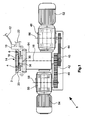
- the in the FIGS. 1 to 3 shown homogenizer consists essentially of a mounted in a housing 2 rotor 4, a likewise disposed within the housing 2 rotatable element 6 for homogenizing and / or conveying and a drive device 8, which drives the rotor 4 and independently thereof the rotatable element 6.
- the homogenizer is by means of a housing or adapter 10 to an agitator or the like.
- the wall 12 is shown, fastened so that from the interior of the agitator container a flowable material through an inlet opening 14 into the interior 16 of the homogenizer axially, ie in the direction of Longitudinal axis 18 can flow.
- a circumferential channel 20 is formed, which has an outlet opening, not shown, which communicates with a return line 22 through which the flowable material is traceable either in the container in the lower region or in the upper region.
- the substance can be transported to a bottling plant.
- the homogenizer can alternatively be set up separately from a container.
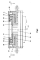
- the rotor 4 has a circular base plate 24 (see. FIG. 2 ) and a plurality of axially projecting from the base plate 24 wings 26, 28, wherein the plurality of wings 26 spaced along an inner circular line to each other and the wings 28 along an outer concentric circle spaced from each other.
- the wings 26 are designed in a manner known per se so that the substance to be homogenized is captured by the wings 26 and transported radially outward (relative to the longitudinal axis 18) and thereby acted upon by shear forces.
- the base plate 24 is coupled to an inner drive shaft 30.
- the rotatable element 6 is formed in the embodiment as a pumping wheel with a plurality of axially projecting from another disc-shaped base plate 32 pump blade 34, which extend along a relative to the blades 26, 28 concentric circle and are designed in a conventional manner so that the flowable material is pumped through the homogenizer in the channel 20 with relatively high pump power.
- the base plate 32 is integrally arranged with a concentric with the drive shaft 30 outer drive shaft 36 which is formed as a hollow shaft coupled.
- the base plates 24 and 32 are arranged substantially parallel to each other.
- stator 38 forming stator elements or rings which are multi-stage, formed in two stages in the embodiment.
- Inner stator elements are disposed between blades 26 and 28, as viewed in the radial direction, and further stator elements are placed between blades 28 and pumping blades 34 of rotatable element 6.
- the drive device 8 with which the rotor 4 and the rotatable element 6 are independently drivable, is described below with reference to FIG FIGS. 1 and 3 explained.
- the drive shafts 30, 36 can by means of fixed to the end portions of gears 40 and 42, timing belt 44 and 46, gears 48, 50 and electric motors 50, 54 are driven so with adjustable speeds in both directions of rotation that the rotor 4 and the rotatable element 6 rotate in the same direction or in opposite directions. Also, the rotor 4 or the rotatable member 6 can be stopped while the other component is rotating.
- the gear 48, 50 and the electric motors 52, 54 can be arranged offset or rotated about longitudinal axes 56, 58.
- the outer drive shaft 36 is supported by means of two bearings 60, 62, which are rolling or plain bearings, in a housing 64, which is flanged to the housing 2 of the homogenizer.
- the base plate 32 of the rotatable member 6 with its pump blades 34 is rotationally connected to an upper end portion of the drive shaft 36 by means of screws 66; Of course, instead of the screws other fasteners or a one-piece design could be used.
- a lid 68 which also determines the bearing 62.
- the inner, the rotor 4 driving drive shaft 30 is rotatably supported by two bearings 70, 72 in the drive shaft 36. All bearings 62, 64, 70, 72 are sufficient with Lubricant filled (“self-lubricating") and fixed with the help of retaining rings and sleeves at the specified positions.
- two mechanical seals 78, 80 are provided, each with four sliding rings.
- other shaft seals such as lip seals o. The like. Be used.
- An upper slip ring of the mechanical seal 78 is fixedly connected to the housing 2, while a lower seal ring is fixed to the drive shaft 36 and rotated therewith, so that flowable material can not flow from the inner space 16 into the interior of the housing 62.
- Upper ring of the mechanical seal 80 is fixed to the inside of the drive shaft 36 and relatively movable to a lower ring of the mechanical seal 80 which is fixedly connected to the outside of the drive shaft 30 so that no flowable material pass the mechanical seal 80 and from the interior 16th can flow into the interior of the housing 64.
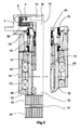
- FIG. 4 partially illustrated embodiment of a homogenizer according to the invention is designed in principle similar to the embodiment described above, so that in order to avoid repetition to the above descriptions, reference is made in full and only differences will be described below.
- the rotor 4 is driven by means of the drive shaft 30, toothed belt 44 and gear 48 and drive motor 52.
- the rotatable member 2 is driven by the outer drive shaft 36, timing belt 46, gear 50 and drive motor 54 independently of the rotor 4.
- the rotatable element 2 is provided with outer, attached to the base plate 32 pumping blades 34 which merge into a radially inwardly directed upper annular disc 82, from which axially in the direction of the base plate 24 projecting in the manner of a stator formed wing or stator elements 84 are formed , which are arranged between the pump blades 34 and the wings 28 and between the wings 26 and 28 and increase the shear effect.
- the stator elements 84 are rotatable together with the rotatable element 2 and the pump blades 34. Since the blades 84 are formed in the manner of a conventional stator and these are rotatable, can also be spoken of a "dynamic stator".
- the rotor 4 which can be driven by means of the drive shaft 30 has a plurality of webs 86 fastened to the base plate 24 and connected to a circular disk 88. From the circular disc 88 projecting axially inwardly projecting in the manner of a stator stator 90 from which are rotatable about the longitudinal axis 18.
- the rotatable element 2 which is coupled to the drive shaft 36, has blade-like blades 92 and outer pump blades 94.
- the stator elements 90 are arranged between pumping wheel 94 and the elements 92.
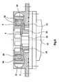
- FIG. 6 Further embodiment shown also referred to the above descriptions and explained below only the differences.
- the coupled to the drive shaft 30 rotor 6 is configured as in the previously with reference to FIG. 5 described embodiment.
- the rotatable by means of the drive shaft 36 element 6 is formed in the manner of a stator and has axially projecting from the base plate 24 stator elements 96.
Landscapes
- Chemical & Material Sciences (AREA)
- Chemical Kinetics & Catalysis (AREA)
- Mixers Of The Rotary Stirring Type (AREA)
- Accessories For Mixers (AREA)
- Processing And Handling Of Plastics And Other Materials For Molding In General (AREA)
- Pharmaceuticals Containing Other Organic And Inorganic Compounds (AREA)
- Transition And Organic Metals Composition Catalysts For Addition Polymerization (AREA)
Claims (11)
- Dispositif d'homogénéisation servant à homogénéiser des substances à écoulement libre,
comportant un rotor (4) logé de manière à pouvoir tourner dans un boîtier (2) et pouvant être entraîné au moyen d'un système d'entraînement (8),
dans lequel le boîtier (2) du dispositif d'homogénéisation présente une ouverture d'entrée (14), par laquelle le matériau à écoulement libre peut entrer de manière axiale dans l'espace intérieur (16), et une ouverture de sortie, par laquelle la substance à écoulement libre homogénéisée sort du boîtier (2) essentiellement de manière radiale et/ou tangentielle,
dans lequel un élément (6) logé de manière à pouvoir tourner dans le boîtier (2) et pouvant être entraîné indépendamment du rotor au moyen d'un système d'entraînement (8) est prévu pour homogénéiser et/ou transporter la substance à écoulement libre,
caractérisé en ce que l'élément (6) pouvant tourner peut être entraîné dans le même sens que le rotor (4) ou dans le sens opposé à ce dernier, et en ce que les moteurs d'entraînement (52), (54) du rotor (4) et de l'élément (6) pouvant tourner peuvent être commandés de telle manière que le rotor (4) et l'élément (6) pouvant tourner peuvent être tournés dans le même sens ou dans le sens opposé à des vitesses relatives réglables ou en ce qu'au choix soit le rotor (4) soit l'élément (6) pouvant tourner est entraîné, tandis que l'autre composant est à l'arrêt. - Système d'homogénéisation selon la revendication 1,
caractérisé en ce que l'élément (6) pouvant tourner est réalisé comme une roue de pompe dotée de plusieurs aubes de pompe (34). - Système d'homogénéisation selon la revendication 2,
caractérisé en ce que l'élément (6) pouvant tourner est réalisé à la manière d'un stator ou d'un rotor doté d'ailettes (84). - Dispositif d'homogénéisation selon l'une quelconque des revendications précédentes,
caractérisé en ce qu'au moins un dispositif d'étanchéité d'arbre, de préférence, une garniture étanche à anneau glissant (78), (80) sont prévus pour étanchéifier l'espace intérieur (16) du boîtier (2) du dispositif d'homogénéisation par rapport à l'environnement. - Dispositif d'homogénéisation selon l'une quelconque des revendications précédentes,
caractérisé en ce que l'élément (6) pouvant tourner et le rotor (4) sont couplés à deux arbres d'entraînement (30), (36) disposés de manière coaxiale l'un par rapport à l'autre et servant à entraîner l'élément (6) pouvant tourner ou le rotor (4), en ce qu'au moins un des deux arbres d'entraînement (30), (36) est réalisé comme un arbre creux, en ce que l'arbre d'entraînement intérieur (30) est logé dans l'arbre d'entraînement extérieur (36) au moyen de paliers de roulement et en ce que l'arbre d'entraînement extérieur (36) est logé de son côté dans un boîtier (64). - Dispositif d'homogénéisation selon l'une quelconque des revendications précédentes,
caractérisé en ce que le rotor (4) et/ou l'élément (6) pouvant tourner présentent une plaque de base (24), (32) couplée à l'arbre d'entraînement (30), (36) associé, de laquelle les ailettes (34), (38) font saillie de manière axiale, en ce que les axes de rotation des arbres d'entraînement (30), (36) sont disposés en fonctionnement essentiellement de manière verticale, et en ce que les arbres d'entraînement sont entraînés au moyen respectivement d'une courroie dentée (44), (46), d'une courroie trapézoidale ou d'une chaîne. - Dispositif d'homogénéisation selon l'une quelconque des revendications précédentes,
caractérisé en ce que les moteurs d'entraînement (52), (54) du rotor (4) et de l'élément (6) pouvant tourner peuvent être commandés de telle manière que le rotor (4) et l'élément (6) pouvant tourner tournent respectivement dans les deux sens de rotation. - Dispositif d'homogénéisation selon la revendication 7,
caractérisé en ce que deux conduites de récupération (22) communiquant avec l'ouverture de sortie du boîtier sont prévues, par lesquelles la substance à écoulement libre peut être récupérée en différents endroits dans un récipient, en fonction de la position d'une soupape de régulation. - Dispositif d'homogénéisation selon l'une quelconque des revendications précédentes,
caractérisé en ce que des dentures de stator (38) immobiles supplémentaires sont disposées au niveau du boîtier (2) du dispositif d'homogénéisation. - Dispositif d'homogénéisation selon l'une quelconque des revendications précédentes,
caractérisé en ce qu'un arbre d'entraînement (30), (36) du rotor (4) et/ou de l'élément (6) pouvant tourner sont entraînés directement au moyen d'un moteur d'entraînement (52, 54). - Procédé servant à homogénéiser des substances à écoulement libre au moyen d'un dispositif d'homogénéisation doté d'un rotor (4) logé de manière à pouvoir tourner dans un boîtier (2) et pouvant être entraîné au moyen d'un système d'entraînement (8),
dans lequel le boîtier (2) du dispositif d'homogénéisation présente une ouverture d'entrée (14), par laquelle le matériau à écoulement libre entre de manière axiale dans l'espace intérieur (16), et une ouverture de sortie, par laquelle la substance à écoulement libre homogénéisée sort du boîtier (2) essentiellement de manière radiale et/ou tangentielle,
dans le cadre duquel la substance à écoulement libre est homogénéisée et/ou transportée au moyen d'un élément (6) logé de manière à pouvoir tourner dans le boîtier (2) et pouvant être entraîné indépendamment du rotor (4) au moyen d'un système d'entraînement (8),
dans lequel l'élément (6) pouvant tourner peut être entraîné dans le même sens ou dans le sens opposé par rapport au rotor (4),
caractérisé en ce que- des moteurs d'entraînement (52), (54) du rotor (4) et de l'élément (6) pouvant tourner peuvent être commandés de telle manière que le rotor (4) et l'élément (6) pouvant tourner peuvent tourner dans le même sens ou dans le sens opposé à des vitesses relatives réglables afin de pouvoir faire varier de manière continue le cisaillement sur la substance,- ou en ce qu'au choix soit le rotor (4) soit l'élément (6) pouvant tourner est entraîné, tandis que l'autre composant respectif est à l'arrêt.
Applications Claiming Priority (2)
| Application Number | Priority Date | Filing Date | Title |
|---|---|---|---|
| DE20002920U DE20002920U1 (de) | 2000-02-18 | 2000-02-18 | Homogenisator |
| EP01103854A EP1125625B1 (fr) | 2000-02-18 | 2001-02-16 | Dispositif d'homogénéisation |
Related Parent Applications (1)
| Application Number | Title | Priority Date | Filing Date |
|---|---|---|---|
| EP01103854A Division EP1125625B1 (fr) | 2000-02-18 | 2001-02-16 | Dispositif d'homogénéisation |
Publications (2)
| Publication Number | Publication Date |
|---|---|
| EP1825907A1 EP1825907A1 (fr) | 2007-08-29 |
| EP1825907B1 true EP1825907B1 (fr) | 2012-10-03 |
Family
ID=7937511
Family Applications (2)
| Application Number | Title | Priority Date | Filing Date |
|---|---|---|---|
| EP01103854A Expired - Lifetime EP1125625B1 (fr) | 2000-02-18 | 2001-02-16 | Dispositif d'homogénéisation |
| EP07106354A Expired - Lifetime EP1825907B1 (fr) | 2000-02-18 | 2001-02-16 | Dispositif d'homogénéisation |
Family Applications Before (1)
| Application Number | Title | Priority Date | Filing Date |
|---|---|---|---|
| EP01103854A Expired - Lifetime EP1125625B1 (fr) | 2000-02-18 | 2001-02-16 | Dispositif d'homogénéisation |
Country Status (5)
| Country | Link |
|---|---|
| US (1) | US6866412B2 (fr) |
| EP (2) | EP1125625B1 (fr) |
| AT (1) | ATE359859T1 (fr) |
| DE (2) | DE20002920U1 (fr) |
| ES (1) | ES2286048T3 (fr) |
Families Citing this family (18)
| Publication number | Priority date | Publication date | Assignee | Title |
|---|---|---|---|---|
| SE9804442D0 (sv) * | 1998-12-21 | 1998-12-21 | Global Powder Ab | Anordning och metod för kontinuerlig blandning |
| US6648500B2 (en) * | 1999-04-13 | 2003-11-18 | International Process Equipment And Technology, Inc. | Rotary pulsation device |
| DE10023694C2 (de) * | 2000-05-16 | 2002-04-04 | Ystral Gmbh Maschb & Processte | Vorrichtungen zum Mischen von Stoffen |
| EP1331988B1 (fr) * | 2000-11-10 | 2006-06-14 | Maelstrom Advanced Process Technologies Ltd | Melangeur dynamique |
| DE10320739B3 (de) | 2003-05-09 | 2004-10-21 | Ika - Werke Gmbh & Co. Kg | Vorrichtung zum Dispergieren und/oder Homogenisieren |
| DE102004025281B4 (de) * | 2004-05-19 | 2008-09-04 | Henkel Ag & Co. Kgaa | Verfahren zur Herstellung von Mitteln zur Färbung keratinischer Fasern |
| SE527867C2 (sv) * | 2004-11-12 | 2006-06-27 | Bjoern Gudmunsson | Kylanordning |
| DE102005017075A1 (de) * | 2005-04-13 | 2006-10-19 | Ekato Unimix Gmbh | Vorrichtung zum Homogenisieren und/oder Dispergieren fliessfähiger Stoffe |
| DE502007001196D1 (de) * | 2006-03-29 | 2009-09-10 | Hebold Mixing & More Gmbh | Homogenisator |
| DE102007016445A1 (de) * | 2007-04-04 | 2008-10-09 | Beiersdorf Ag | Verfahren zur Herstellung fließfähiger kationischer Emulsionen |
| US7887862B2 (en) * | 2007-10-10 | 2011-02-15 | Industrias Centli S.A. De C.V. | Method and apparatus for separating, purifying, promoting interaction and improving combustion |
| DE102009047777A1 (de) | 2009-09-30 | 2011-04-07 | Azo Holding Gmbh | Homogenisator und Homogenisiervorrichtung mit einem solchen Homogenisator |
| FR2952641B1 (fr) * | 2009-11-18 | 2012-01-13 | Lfb Biomedicaments | Procede de traitement du plasma sanguin comprenant une etape de lavage par dispersion |
| JP2011147936A (ja) * | 2010-09-29 | 2011-08-04 | Sintokogio Ltd | 剪断式分散装置、循環式分散システム及び循環式分散方法 |
| KR101780329B1 (ko) * | 2015-05-06 | 2017-09-20 | 주식회사 케이엔에스컴퍼니 | 로터-로터 방식 분산유화장치 임펠러 구조 시스템 |
| DE202016000169U1 (de) | 2016-01-14 | 2017-04-20 | Symex Gmbh & Co. Kg | Pump- und/oder Mischeinrichtung zum Fördern, Homogenisieren und/oder Dispergieren fließfähiger Produkte |
| KR101992949B1 (ko) * | 2017-09-21 | 2019-06-26 | 주식회사 우원 | 면상 온도 센서를 구비한 원료 균질화 설비 |
| DE202018102804U1 (de) | 2018-05-18 | 2019-08-22 | Symex Gmbh & Co. Kg | Vorrichtung zum Homogenisieren fließfähiger Stoffe |
Family Cites Families (75)
| Publication number | Priority date | Publication date | Assignee | Title |
|---|---|---|---|---|
| DE183671C (fr) | ||||
| US204124A (en) * | 1878-05-28 | Improvement in churns | ||
| FR606508A (fr) | 1924-11-19 | 1926-06-15 | Perfectionnements aux appareils centrifuges pour émulsionner, mélanger ou pulvériser des substances quelconques liquides, semiliquides ou sèches | |
| US1624037A (en) * | 1925-04-30 | 1927-04-12 | Colloidal Equipment Corp | Apparatus for deflocculating and emulsifying |
| DE553055C (de) | 1929-10-08 | 1932-06-21 | Paul Griese | Schleudermuehle |
| GB665981A (en) * | 1946-10-04 | 1952-02-06 | Robert John Jay | Improvements in or relating to methods of and apparatus for emulsifying liquids |
| US2685436A (en) | 1950-08-31 | 1954-08-03 | Goodrich Co B F | Apparatus for foaming liquids |
| US2723110A (en) * | 1953-12-21 | 1955-11-08 | Lowell J Collins | Sanitary bearing and shaft combination |
| CH389577A (de) | 1960-06-24 | 1965-03-31 | Physik Chem Forschungsinstitut | Misch- und Dispergiervorrichtung |
| US3224744A (en) * | 1962-03-19 | 1965-12-21 | Day J H Co | Vertical mixer construction |
| FR1455028A (fr) | 1963-12-23 | 1966-04-01 | Procédé et appareil pour le travail instantané de matières farineuses, applicables notamment à la préparation instantanée de pâtes de plâtres traités | |
| US3271194A (en) * | 1964-01-27 | 1966-09-06 | Yokohama Seito Kabushiki Kaish | Solidification of saccharide solutions |
| US3308171A (en) * | 1964-07-17 | 1967-03-07 | Yokohama Seito Kabushiki Kaish | Method for producing granular or powdery sorbitol from sorbitol solution |
| US3580546A (en) * | 1968-09-05 | 1971-05-25 | Kaydon Technical Enterprises L | Device for mixing and proportioning liquids |
| US3731800A (en) * | 1970-11-27 | 1973-05-08 | Polaroid Corp | Counter-current centrifugal device and use |
| US3845938A (en) * | 1972-09-27 | 1974-11-05 | G Schold | Apparatus for dispersing finely divided solid particles in a liquid vehicle |
| DK133269C (da) | 1974-03-26 | 1976-09-20 | Rotostat Is | Blandeaggregat til blanding og eller bearbejdning af flydendematerialer |
| US3929318A (en) | 1974-12-09 | 1975-12-30 | Exxon Research Engineering Co | Static mixers for viscous material |
| US4019722A (en) * | 1975-11-28 | 1977-04-26 | Littleford Bros. Inc. | High intensity mixer utilizing a single speed motor |
| US4198168A (en) | 1978-04-12 | 1980-04-15 | Liquid Control Incorporated | Phase blending static mixing process and apparatus |
| US4222671A (en) * | 1978-09-05 | 1980-09-16 | Gilmore Oscar Patrick | Static mixer |
| EP0013547A1 (fr) | 1978-12-21 | 1980-07-23 | WAROP Industrie Aktiengesellschaft | Procédé de préparation d'une suspension ou d'une émulsion aqueuse stable d'un combustible |
| AT363862B (de) | 1979-02-12 | 1981-09-10 | Central Intertrade Finance | Verfahren zur aktivierung von wasser, zum zwecke der wachstumsfoerderung sowie desintegrator und vorrichtung zur durchfuehrung des verfahrens |
| CH642564A5 (de) | 1979-10-26 | 1984-04-30 | Sulzer Ag | Statische mischvorrichtung. |
| GB2077618A (en) * | 1980-06-13 | 1981-12-23 | Rtl Contactor Holding Sa | Contactor |
| DE3027567A1 (de) * | 1980-07-21 | 1982-02-25 | Dieter 6570 Kirn Kupka | Ruehrwerk mit zwei um dieselbe geometrische achse gegenlaeufig angetriebenen ruehrorganen |
| AT375417B (de) * | 1980-11-25 | 1984-08-10 | Escher Wyss Gmbh | Dispergiervorrichtung fuer die aufbereitung von altpapierstoff |
| DE3212642A1 (de) | 1981-04-14 | 1982-11-18 | Desro Patentverwertungs Ag | Verfahren zur zubereitung von brennstoffen oder brennstoffkomponenten, nach dem verfahren zubereitete brennstoffe und vorrichtung zur durchfuehrung des verfahrens |
| DD205076A1 (de) | 1981-09-04 | 1983-12-21 | Klaus Hoppe | Kontaktiereinrichtung zum kontinuierlichen statischen mischen und verteilen fliessfaehiger stoffe |
| JPS5939174B2 (ja) | 1982-02-01 | 1984-09-21 | 名友産業株式会社 | 流体混合装置 |
| DE3220092A1 (de) | 1982-05-28 | 1983-12-01 | Janke & Kunkel GmbH & Co KG Ika - Werk, 7813 Staufen | Dispergiervorrichtung |
| DE8215535U1 (de) | 1982-05-28 | 1985-07-11 | Janke & Kunkel GmbH & Co KG Ika - Werk, 7813 Staufen | Dispergiervorrichtung |
| DE3417242A1 (de) | 1984-05-10 | 1985-11-14 | Haagen & Rinau | Homogenisiereinrichtung |
| DE8414202U1 (de) | 1984-05-10 | 1987-07-23 | Haagen & Rinau Mischtechnik Gmbh, 2800 Bremen | Homogenisiereinrichtung |
| US4582432A (en) | 1984-12-20 | 1986-04-15 | Usm Corporation | Rotary processors and methods for mixing low viscosity liquids with viscous materials |
| JPS61268344A (ja) * | 1985-01-22 | 1986-11-27 | Funken:Kk | 微粉炭、オイルコ−クス等の粉体をスラリ−化するための連続混練方法及びその装置 |
| CH665959A5 (de) * | 1985-04-03 | 1988-06-30 | Miteco Ag | Vorrichtung zum durchmischen von zumindest einem stroemungsmedium. |
| DE3520040A1 (de) * | 1985-06-04 | 1986-12-04 | Herfeld, Friedrich Walter, Dr., 5982 Neuenrade | Vorrichtung zum mischen von gut |
| US4889428A (en) * | 1985-07-29 | 1989-12-26 | Concrete Technology Corporation | Rotary mill |
| JPS631430A (ja) * | 1986-06-20 | 1988-01-06 | Ishiyama Bunyo | 粉粒体の高速溶解湿潤方法 |
| DE3715331A1 (de) | 1987-05-08 | 1988-12-01 | Berents Gmbh & Co Kg A | Homogenisator fuer die herstellung fliessfaehiger produkte |
| FR2620044B1 (fr) * | 1987-09-08 | 1989-12-22 | Pillon Francis | Procede et dispositif pour epandre ou melanger des pulverulents par depot de particules en suspension dans l'air |
| DD293059A5 (de) | 1987-12-11 | 1991-08-22 | ���������������������k | Vorrichtung zur homogenisierung von substanzen mit unterschiedlichen aggregatzustaenden |
| US4848920A (en) * | 1988-02-26 | 1989-07-18 | Husky Injection Molding Systems Ltd. | Static mixer |
| DE3810609A1 (de) * | 1988-03-29 | 1989-10-12 | Fryma Masch Ag | Vorrichtung zum mischen und homogenisieren von fliessfaehigen produkten |
| JP2646111B2 (ja) * | 1988-06-27 | 1997-08-25 | 日本コム株式会社 | 連続流通攪拌装置 |
| JPH0265743U (fr) | 1988-11-04 | 1990-05-17 | ||
| US4878677A (en) * | 1988-12-15 | 1989-11-07 | Hydrochem Developments Ltd. | Shut off seal about a shaft of a device having a side entry into a tank |
| DD280048A1 (de) | 1989-02-24 | 1990-06-27 | Univ Halle Wittenberg | Vorrichtung zur umsetzung von feststoffen in oder mit fluessigkeiten |
| FI895593A (fi) | 1989-11-22 | 1991-05-23 | Flowcon Oy | Anordning i synnerhet foer behandling av kraemer och pastor. |
| US5309403A (en) * | 1991-07-10 | 1994-05-03 | Complete Automation, Inc. | Modular continuous flow paint delivery system |
| DE4209527A1 (de) | 1992-03-24 | 1993-09-30 | Dorr Oliver Deutschland | Homogenisiermaschine |
| US5253937A (en) * | 1992-06-29 | 1993-10-19 | Nalco Chemical Company | Method and apparatus for dispersing or dissolving particles of a pelletized material in a liquid |
| DK150692A (da) * | 1992-12-16 | 1994-06-17 | Niro Holding As | Fremgangsmåde ved injektion af et første fluidum i et andet fluidum og apparat til udøvelse af fremgangsmåden |
| DE9305553U1 (de) | 1993-04-15 | 1993-05-19 | Koruma Maschinenbau Gmbh, 7844 Neuenburg | Homogenisiervorrichtung o.dgl. |
| US5460444A (en) * | 1993-04-28 | 1995-10-24 | Howorka; Franz | Apparatus for the treatment of solid, liquid and/or gaseous materials |
| EP0646408B1 (fr) | 1993-10-05 | 1999-12-01 | Sulzer Chemtech AG | Dispositif pour homogéniser des liquides très visqueux |
| ES2148302T3 (es) | 1994-03-09 | 2000-10-16 | Sulzer Chemtech Ag | Elemento estructural plano y guarnecido a partir del mismo. |
| DE4433039B4 (de) * | 1994-09-16 | 2006-11-16 | Richard Frisse Gmbh | Vorrichtungen zum Bearbeiten von Dispersionen |
| DE19614295A1 (de) | 1995-04-21 | 1996-10-24 | Friedrich Dr Ing Vock | Verfahren und Vorrichtung zum Nassmahlen und Dispergieren von Feststoffpartikeln in Flüssigkeiten |
| AU5342896A (en) | 1995-04-21 | 1996-11-07 | William Ferguson Watson | Mixing |
| DE59508992D1 (de) | 1995-06-21 | 2001-03-01 | Sulzer Chemtech Ag Winterthur | In einem Rohr angeordneter Mischer |
| EP0760253B1 (fr) | 1995-08-30 | 1999-05-06 | Sulzer Chemtech AG | Mélangeur statique pour fluides visqueux |
| BE1009675A3 (nl) * | 1995-09-27 | 1997-06-03 | Haegeman J H | Toestel voor het behandelen van vloeistoffen. |
| JP3595892B2 (ja) * | 1995-12-20 | 2004-12-02 | 有限会社勝製作所 | 合成樹脂原料の攪拌装置 |
| JP3127115B2 (ja) | 1996-02-29 | 2001-01-22 | 東京日進ジャバラ株式会社 | 静的混合装置 |
| DE29608713U1 (de) | 1996-05-14 | 1996-08-08 | Wittek, Axel, 25582 Hohenaspe | Dispergiereinrichtung |
| JPH10370A (ja) * | 1996-06-13 | 1998-01-06 | Kansai Matetsuku Kk | 粉砕ピン式粉砕機 |
| ES2151650T3 (es) | 1996-07-05 | 2001-01-01 | Sulzer Chemtech Ag | Mezclador estatico. |
| CA2294445A1 (fr) | 1997-06-20 | 1998-12-30 | Kankyou Kagaku Kougyou Kabushiki Kaisya | Melangeur de fluide statique |
| DE19837671A1 (de) | 1998-08-20 | 2000-02-24 | Bayer Ag | Statischer Mischer |
| EP0988887B1 (fr) | 1998-08-25 | 2003-02-05 | Vakumix Rühr- und Homogenisiertechnik Aktiengesellschaft | Homogénisateur avec un dispositif de protection sur le rotor |
| DE10005457A1 (de) | 2000-02-08 | 2001-08-09 | Bayer Ag | Statischer Mischer |
| DE10103425A1 (de) | 2001-01-26 | 2002-08-01 | Basf Ag | Statischer Mischer mit geschichtetem Aufbau |
| EP1437173B1 (fr) | 2002-12-13 | 2006-01-11 | Sulzer Chemtech AG | Mélangeur statique pour milieux très visqueux |
-
2000
- 2000-02-18 DE DE20002920U patent/DE20002920U1/de not_active Expired - Lifetime
-
2001
- 2001-02-15 US US09/784,637 patent/US6866412B2/en not_active Expired - Lifetime
- 2001-02-16 ES ES01103854T patent/ES2286048T3/es not_active Expired - Lifetime
- 2001-02-16 EP EP01103854A patent/EP1125625B1/fr not_active Expired - Lifetime
- 2001-02-16 EP EP07106354A patent/EP1825907B1/fr not_active Expired - Lifetime
- 2001-02-16 DE DE50112352T patent/DE50112352D1/de not_active Expired - Lifetime
- 2001-02-16 AT AT01103854T patent/ATE359859T1/de active
Also Published As
| Publication number | Publication date |
|---|---|
| ES2286048T3 (es) | 2007-12-01 |
| EP1125625B1 (fr) | 2007-04-18 |
| US6866412B2 (en) | 2005-03-15 |
| ATE359859T1 (de) | 2007-05-15 |
| EP1825907A1 (fr) | 2007-08-29 |
| US20010036125A1 (en) | 2001-11-01 |
| DE20002920U1 (de) | 2000-04-20 |
| EP1125625A3 (fr) | 2002-01-30 |
| DE50112352D1 (de) | 2007-05-31 |
| EP1125625A2 (fr) | 2001-08-22 |
Similar Documents
| Publication | Publication Date | Title |
|---|---|---|
| EP1825907B1 (fr) | Dispositif d'homogénéisation | |
| DE69329469T2 (de) | Fluegelzellenmaschine | |
| EP0802879B1 (fr) | Dispositif pour doser des produits en vrac | |
| EP3202489B1 (fr) | Dispositif destiné à homogénéiser et/ou disperser des produits fluides | |
| EP2219917B1 (fr) | Pompe à vide | |
| EP3894706A1 (fr) | Pompe à piston rotatif avec palier interne | |
| EP2305370B1 (fr) | Homogénéisateur et dispositif d'homogénéisation doté d'un tel homogénéisateur | |
| DE2643560C2 (de) | Rührvorrichtung | |
| EP0946303B1 (fr) | Machine de reduction en morceaux pourvue d'un emulgateur | |
| EP1470856A1 (fr) | Agitateur pur mélanger, homogénéiser et disperser | |
| EP0645179B1 (fr) | Moulin à frottement et malaxeur contenant ledit moulin | |
| DE4337761A1 (de) | Rotierendes Maschinenteil, insbesondere Rotor eines Zykloidal-Schiffspropellers | |
| EP0801974B1 (fr) | Dispositif d'homogénéisation et/ou de dispersion d'un matériau apte à écoulement libre | |
| DE2219352A1 (de) | Kontinuierlich arbeitender ringmischer | |
| EP3572145B1 (fr) | Dispositif et procédé d'homogénéisation des substances coulantes | |
| EP0832682A1 (fr) | Appareil d'homogénéisation et dispersion de phases liquides | |
| EP0740953B1 (fr) | Dispositif pour le broyage et le mixage des masses | |
| EP0930093A2 (fr) | Dispositif pour agiter un mélange ainsi que l'utilisation du dispositif | |
| EP2001581B1 (fr) | Homogénéisateur | |
| DE102004055611B4 (de) | Vorrichtung, insbesondere zum Antrieb eines eine Hubbewegung und eine Schwenkbewegung ausführenden Organs | |
| DE3243169A1 (de) | Stroemungsmaschine | |
| DE1461014C (de) | Scheibenmühle für stückiges pflanzliches Gut | |
| DE3150569A1 (de) | Fluegelzellenpumpe | |
| DE1813215A1 (de) | Vorrichtung zur UEbertragung einer Drehbewegung von einem Antrieb auf einen von diesem entfernt liegenden Abtrieb | |
| DE1247128B (de) | Reibscheibenmuehle zum Zerreiben, Loesen, Mischen, Emulgieren od. dgl. von aus festen und fluessigen Komponenten bestehenden Stoffgemischen |
Legal Events
| Date | Code | Title | Description |
|---|---|---|---|
| PUAI | Public reference made under article 153(3) epc to a published international application that has entered the european phase |
Free format text: ORIGINAL CODE: 0009012 |
|
| AC | Divisional application: reference to earlier application |
Ref document number: 1125625 Country of ref document: EP Kind code of ref document: P |
|
| AK | Designated contracting states |
Kind code of ref document: A1 Designated state(s): AT BE CH CY DE DK ES FI FR GB GR IE IT LI LU MC NL PT SE TR |
|
| 17P | Request for examination filed |
Effective date: 20080218 |
|
| 17Q | First examination report despatched |
Effective date: 20080331 |
|
| AKX | Designation fees paid |
Designated state(s): AT BE CH CY DE DK ES FI FR GB GR IE IT LI LU MC NL PT SE TR |
|
| GRAP | Despatch of communication of intention to grant a patent |
Free format text: ORIGINAL CODE: EPIDOSNIGR1 |
|
| GRAS | Grant fee paid |
Free format text: ORIGINAL CODE: EPIDOSNIGR3 |
|
| GRAA | (expected) grant |
Free format text: ORIGINAL CODE: 0009210 |
|
| AC | Divisional application: reference to earlier application |
Ref document number: 1125625 Country of ref document: EP Kind code of ref document: P |
|
| AK | Designated contracting states |
Kind code of ref document: B1 Designated state(s): AT BE CH CY DE DK ES FI FR GB GR IE IT LI LU MC NL PT SE TR |
|
| REG | Reference to a national code |
Ref country code: GB Ref legal event code: FG4D Free format text: NOT ENGLISH |
|
| REG | Reference to a national code |
Ref country code: CH Ref legal event code: NV Representative=s name: E. BLUM & CO. AG PATENT- UND MARKENANWAELTE VSP Ref country code: CH Ref legal event code: EP Ref country code: AT Ref legal event code: REF Ref document number: 577708 Country of ref document: AT Kind code of ref document: T Effective date: 20121015 |
|
| REG | Reference to a national code |
Ref country code: IE Ref legal event code: FG4D Free format text: LANGUAGE OF EP DOCUMENT: GERMAN |
|
| REG | Reference to a national code |
Ref country code: DE Ref legal event code: R096 Ref document number: 50116182 Country of ref document: DE Effective date: 20121129 |
|
| REG | Reference to a national code |
Ref country code: NL Ref legal event code: VDEP Effective date: 20121003 |
|
| PG25 | Lapsed in a contracting state [announced via postgrant information from national office to epo] |
Ref country code: FI Free format text: LAPSE BECAUSE OF FAILURE TO SUBMIT A TRANSLATION OF THE DESCRIPTION OR TO PAY THE FEE WITHIN THE PRESCRIBED TIME-LIMIT Effective date: 20121003 Ref country code: SE Free format text: LAPSE BECAUSE OF FAILURE TO SUBMIT A TRANSLATION OF THE DESCRIPTION OR TO PAY THE FEE WITHIN THE PRESCRIBED TIME-LIMIT Effective date: 20121003 Ref country code: NL Free format text: LAPSE BECAUSE OF FAILURE TO SUBMIT A TRANSLATION OF THE DESCRIPTION OR TO PAY THE FEE WITHIN THE PRESCRIBED TIME-LIMIT Effective date: 20121003 |
|
| PG25 | Lapsed in a contracting state [announced via postgrant information from national office to epo] |
Ref country code: PT Free format text: LAPSE BECAUSE OF FAILURE TO SUBMIT A TRANSLATION OF THE DESCRIPTION OR TO PAY THE FEE WITHIN THE PRESCRIBED TIME-LIMIT Effective date: 20130204 Ref country code: CY Free format text: LAPSE BECAUSE OF FAILURE TO SUBMIT A TRANSLATION OF THE DESCRIPTION OR TO PAY THE FEE WITHIN THE PRESCRIBED TIME-LIMIT Effective date: 20121003 Ref country code: GR Free format text: LAPSE BECAUSE OF FAILURE TO SUBMIT A TRANSLATION OF THE DESCRIPTION OR TO PAY THE FEE WITHIN THE PRESCRIBED TIME-LIMIT Effective date: 20130104 |
|
| PG25 | Lapsed in a contracting state [announced via postgrant information from national office to epo] |
Ref country code: DK Free format text: LAPSE BECAUSE OF FAILURE TO SUBMIT A TRANSLATION OF THE DESCRIPTION OR TO PAY THE FEE WITHIN THE PRESCRIBED TIME-LIMIT Effective date: 20121003 |
|
| PLBE | No opposition filed within time limit |
Free format text: ORIGINAL CODE: 0009261 |
|
| STAA | Information on the status of an ep patent application or granted ep patent |
Free format text: STATUS: NO OPPOSITION FILED WITHIN TIME LIMIT |
|
| BERE | Be: lapsed |
Owner name: SYMEX G.M.B.H. & CO. KG Effective date: 20130228 |
|
| 26N | No opposition filed |
Effective date: 20130704 |
|
| PG25 | Lapsed in a contracting state [announced via postgrant information from national office to epo] |
Ref country code: MC Free format text: LAPSE BECAUSE OF NON-PAYMENT OF DUE FEES Effective date: 20130228 |
|
| PG25 | Lapsed in a contracting state [announced via postgrant information from national office to epo] |
Ref country code: ES Free format text: LAPSE BECAUSE OF FAILURE TO SUBMIT A TRANSLATION OF THE DESCRIPTION OR TO PAY THE FEE WITHIN THE PRESCRIBED TIME-LIMIT Effective date: 20130114 |
|
| REG | Reference to a national code |
Ref country code: DE Ref legal event code: R097 Ref document number: 50116182 Country of ref document: DE Effective date: 20130704 |
|
| REG | Reference to a national code |
Ref country code: IE Ref legal event code: MM4A |
|
| PG25 | Lapsed in a contracting state [announced via postgrant information from national office to epo] |
Ref country code: BE Free format text: LAPSE BECAUSE OF NON-PAYMENT OF DUE FEES Effective date: 20130228 Ref country code: IE Free format text: LAPSE BECAUSE OF NON-PAYMENT OF DUE FEES Effective date: 20130216 |
|
| REG | Reference to a national code |
Ref country code: AT Ref legal event code: MM01 Ref document number: 577708 Country of ref document: AT Kind code of ref document: T Effective date: 20130216 |
|
| PG25 | Lapsed in a contracting state [announced via postgrant information from national office to epo] |
Ref country code: AT Free format text: LAPSE BECAUSE OF NON-PAYMENT OF DUE FEES Effective date: 20130216 |
|
| PG25 | Lapsed in a contracting state [announced via postgrant information from national office to epo] |
Ref country code: TR Free format text: LAPSE BECAUSE OF FAILURE TO SUBMIT A TRANSLATION OF THE DESCRIPTION OR TO PAY THE FEE WITHIN THE PRESCRIBED TIME-LIMIT Effective date: 20121003 |
|
| PG25 | Lapsed in a contracting state [announced via postgrant information from national office to epo] |
Ref country code: LU Free format text: LAPSE BECAUSE OF NON-PAYMENT OF DUE FEES Effective date: 20130216 |
|
| REG | Reference to a national code |
Ref country code: FR Ref legal event code: PLFP Year of fee payment: 16 |
|
| REG | Reference to a national code |
Ref country code: FR Ref legal event code: PLFP Year of fee payment: 17 |
|
| REG | Reference to a national code |
Ref country code: FR Ref legal event code: PLFP Year of fee payment: 18 |
|
| PGFP | Annual fee paid to national office [announced via postgrant information from national office to epo] |
Ref country code: GB Payment date: 20200225 Year of fee payment: 20 Ref country code: DE Payment date: 20200304 Year of fee payment: 20 |
|
| PGFP | Annual fee paid to national office [announced via postgrant information from national office to epo] |
Ref country code: CH Payment date: 20200224 Year of fee payment: 20 |
|
| PGFP | Annual fee paid to national office [announced via postgrant information from national office to epo] |
Ref country code: FR Payment date: 20200220 Year of fee payment: 20 |
|
| REG | Reference to a national code |
Ref country code: DE Ref legal event code: R071 Ref document number: 50116182 Country of ref document: DE |
|
| REG | Reference to a national code |
Ref country code: CH Ref legal event code: PL |
|
| REG | Reference to a national code |
Ref country code: GB Ref legal event code: PE20 Expiry date: 20210215 |
|
| PG25 | Lapsed in a contracting state [announced via postgrant information from national office to epo] |
Ref country code: GB Free format text: LAPSE BECAUSE OF EXPIRATION OF PROTECTION Effective date: 20210215 |
|
| PG25 | Lapsed in a contracting state [announced via postgrant information from national office to epo] |
Ref country code: IT Free format text: LAPSE BECAUSE OF NON-PAYMENT OF DUE FEES Effective date: 20200216 |