EP1825907B1 - Homogenising device - Google Patents
Homogenising device Download PDFInfo
- Publication number
- EP1825907B1 EP1825907B1 EP07106354A EP07106354A EP1825907B1 EP 1825907 B1 EP1825907 B1 EP 1825907B1 EP 07106354 A EP07106354 A EP 07106354A EP 07106354 A EP07106354 A EP 07106354A EP 1825907 B1 EP1825907 B1 EP 1825907B1
- Authority
- EP
- European Patent Office
- Prior art keywords
- rotor
- rotatable element
- homogenizer
- housing
- manner
- Prior art date
- Legal status (The legal status is an assumption and is not a legal conclusion. Google has not performed a legal analysis and makes no representation as to the accuracy of the status listed.)
- Expired - Lifetime
Links
Images


Classifications
-
- B—PERFORMING OPERATIONS; TRANSPORTING
- B01—PHYSICAL OR CHEMICAL PROCESSES OR APPARATUS IN GENERAL
- B01F—MIXING, e.g. DISSOLVING, EMULSIFYING OR DISPERSING
- B01F27/00—Mixers with rotary stirring devices in fixed receptacles; Kneaders
- B01F27/27—Mixers with stator-rotor systems, e.g. with intermeshing teeth or cylinders or having orifices
- B01F27/271—Mixers with stator-rotor systems, e.g. with intermeshing teeth or cylinders or having orifices with means for moving the materials to be mixed radially between the surfaces of the rotor and the stator
-
- B—PERFORMING OPERATIONS; TRANSPORTING
- B01—PHYSICAL OR CHEMICAL PROCESSES OR APPARATUS IN GENERAL
- B01F—MIXING, e.g. DISSOLVING, EMULSIFYING OR DISPERSING
- B01F27/00—Mixers with rotary stirring devices in fixed receptacles; Kneaders
- B01F27/40—Mixers with rotor-rotor system, e.g. with intermeshing teeth
- B01F27/41—Mixers with rotor-rotor system, e.g. with intermeshing teeth with the mutually rotating surfaces facing each other
- B01F27/411—Mixers with rotor-rotor system, e.g. with intermeshing teeth with the mutually rotating surfaces facing each other provided with intermeshing elements
Definitions
- the invention relates to a homogenizer for homogenizing flowable substances, with a rotatably mounted in a housing and driven by a drive means rotor.
- homogenizers are used, for example, in the cosmetic, pharmaceutical or chemical industry in the preparation of creams, ointments, pastes or the like.
- the homogenizer is z. B. arranged at the lowest point of a container and homogenized and / or dispersed the flowable material by the rotor together with a stationary stator shearing forces applied to the fabric.
- the homogenizer could also be placed separately next to or between two containers.
- the homogenised substance can either be returned to the container or to a bottling plant.
- the homogenization can be influenced in known homogenizers essentially by varying the rotational speed of the rotor relative to the fixed stator or by the specific design of the rotor and / or the stator. At high speeds, the shearing action and the conveying action of the homogenizer is greater than at low speeds.
- a disadvantage of the known homogenizers is that the shearing action and the conveying action are coupled directly to each other. In addition, it is necessary for the achievement of high shear effects and speeds of the rotor to design the drive devices and drive motors accordingly consuming.
- Another disadvantage is that at too high a speed of the engine, the shearing action is so great that the substance to be homogenized can be adversely affected or possibly even damaged.
- homogenizers In order to meet the requirement of high pumping capacity (conveying effect) and at the same time be able to reduce the shearing action at high speeds, homogenizers have been developed which allow an axial displacement of the rotor relative to the stator in order to control the free flow cross sections (or gaps) between the two To increase the wings of the rotor and the stator (cf. DE 296 08 712 or DE 24 13 452 ). The design effort for such axial displacement is very high.
- FR 606.508 discloses a centrifugal device for emulsifying, mixing or pulverizing liquids, semi-liquids or dry substances, in which a shearing action is set by the axial distance between two rotating disks.
- the patent DE 553 055 discloses a spin mill with a high-speed centrifugal disc loaded with pin rings and one of these opposed coaxially arranged, slow-moving and Mit supportivekränzen occupied driver disc, the pin and Mit supportivekränze interlock and rotate in the same or opposite sense.
- the publication WO 91/07223 discloses an apparatus for processing blends and pastes constructed according to the same principle.
- US 4,786,183 discloses a mixing device having a plurality of pump impellers arranged along a common axis with the immediately adjacent impeller impellers rotating in opposite directions.
- the publication DE 42 09 527 A1 discloses a homogenizing machine in which two rotors run in a housing against each other, wherein the one rotor has a frusto-conical surface and the second rotor with its surface is formed gap-forming the first rotor and both surfaces of the rotors are provided with shear forces generating means.
- the object of the present invention is to provide a homogenizer with which the homogenization effect can be influenced in a structurally simple manner and the shearing action and the pumping action can be adapted to the respective requirements.
- the invention solves this problem by a homogenizer with the features of claim 1 and a method according to claim 11.
- the advantages of the invention consist essentially in the fact that can be influenced by the additional, separately and independently driven by the rotor element homogenization and promotion in a variety of ways and adapted to the respective production requirements.
- the shearing action of the rotor and the rotatable member on the fabric can be adjusted.
- the rotatable element can be driven in the same direction or in opposite directions to the rotor in order to be able to vary the shearing action steplessly within large areas.
- the shearing action can be varied independently of the delivery rate (i.e., the delivery rate of the substance).
- the pumping power can be kept constant at a speed-dependent value, while the shearing action approaches zero at the same or approximately the same rotational speed in the same direction of rotation when the rotatable element rotates.
- the shearing action is maximal, and for the same shearing action, a substantially lower absolute rotational speed is necessary in comparison to conventional homogenizers.
- the drives of the homogenizer according to the invention can be designed for lower rotational speeds.
- the rotatable element is designed as a pumping wheel with a plurality of pumping blades, in order to be able to achieve high pumping powers, while the rotor essentially produces the shearing action of the homogenizer.
- the rotatable element is designed in the manner of a stator or a rotor with vanes. This is basically a homogenizer with a "rotatable stator” in order to produce the maximum shear described above.
- the rotatable element and the rotor are coupled to two coaxial drive shafts for driving the rotatable element or the rotor.
- This simple design solution saves space.
- one of the two drive shafts is preferably designed as a hollow shaft.
- the storage of the drive shafts is expediently designed so that the inner drive shaft is mounted by means of rolling bearings in the outer shaft and the outer shaft is in turn mounted in a housing.
- a structurally simple design of the rotor and the rotatable element provides that the rotor and / or the rotatable element has a base plate coupled to the associated drive shaft, from which the wings protrude axially, that the axes of rotation of the drive shafts in operation is arranged substantially vertically and that the shafts are driven by means of a toothed belt.
- a toothed belt chains instead of a toothed belt chains, V-belts, friction wheels, gears o. The like. Be used.
- the shearing action and the pumping action can be varied easily by controlling the drive motors of the rotor and of the rotatable element such that the rotor and the rotatable element have adjustable relative speeds can be rotated in the same direction or in opposite directions or selectively either the rotor or the rotatable element are driven while the other component is stationary.
- the invention provides that the housing of the homogenizer has an inlet opening, through which flowable material from a container can flow axially into the interior space, and an outlet opening through which the homogenized flowable material flows out of the housing substantially radially and / or tangentially.
- a further preferred embodiment provides that two return lines communicating with the outlet opening of the housing are provided, through which the flowable substance can be returned to different locations in the container, depending on the position of a control valve. In this way, the substance, for example, top recycled into the container or near the homogenizer, which is useful for small amounts of a substance to be homogenized.
- the shearing effect can be further optimized by arranging additional, stationary stator toothings on a housing of the homogenizer.
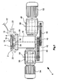
- the in the FIGS. 1 to 3 shown homogenizer consists essentially of a mounted in a housing 2 rotor 4, a likewise disposed within the housing 2 rotatable element 6 for homogenizing and / or conveying and a drive device 8, which drives the rotor 4 and independently thereof the rotatable element 6.
- the homogenizer is by means of a housing or adapter 10 to an agitator or the like.
- the wall 12 is shown, fastened so that from the interior of the agitator container a flowable material through an inlet opening 14 into the interior 16 of the homogenizer axially, ie in the direction of Longitudinal axis 18 can flow.
- a circumferential channel 20 is formed, which has an outlet opening, not shown, which communicates with a return line 22 through which the flowable material is traceable either in the container in the lower region or in the upper region.
- the substance can be transported to a bottling plant.
- the homogenizer can alternatively be set up separately from a container.
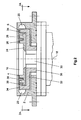
- the rotor 4 has a circular base plate 24 (see. FIG. 2 ) and a plurality of axially projecting from the base plate 24 wings 26, 28, wherein the plurality of wings 26 spaced along an inner circular line to each other and the wings 28 along an outer concentric circle spaced from each other.
- the wings 26 are designed in a manner known per se so that the substance to be homogenized is captured by the wings 26 and transported radially outward (relative to the longitudinal axis 18) and thereby acted upon by shear forces.
- the base plate 24 is coupled to an inner drive shaft 30.
- the rotatable element 6 is formed in the embodiment as a pumping wheel with a plurality of axially projecting from another disc-shaped base plate 32 pump blade 34, which extend along a relative to the blades 26, 28 concentric circle and are designed in a conventional manner so that the flowable material is pumped through the homogenizer in the channel 20 with relatively high pump power.
- the base plate 32 is integrally arranged with a concentric with the drive shaft 30 outer drive shaft 36 which is formed as a hollow shaft coupled.
- the base plates 24 and 32 are arranged substantially parallel to each other.
- stator 38 forming stator elements or rings which are multi-stage, formed in two stages in the embodiment.
- Inner stator elements are disposed between blades 26 and 28, as viewed in the radial direction, and further stator elements are placed between blades 28 and pumping blades 34 of rotatable element 6.
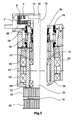
- the drive device 8 with which the rotor 4 and the rotatable element 6 are independently drivable, is described below with reference to FIG FIGS. 1 and 3 explained.
- the drive shafts 30, 36 can by means of fixed to the end portions of gears 40 and 42, timing belt 44 and 46, gears 48, 50 and electric motors 50, 54 are driven so with adjustable speeds in both directions of rotation that the rotor 4 and the rotatable element 6 rotate in the same direction or in opposite directions. Also, the rotor 4 or the rotatable member 6 can be stopped while the other component is rotating.
- the gear 48, 50 and the electric motors 52, 54 can be arranged offset or rotated about longitudinal axes 56, 58.
- the outer drive shaft 36 is supported by means of two bearings 60, 62, which are rolling or plain bearings, in a housing 64, which is flanged to the housing 2 of the homogenizer.
- the base plate 32 of the rotatable member 6 with its pump blades 34 is rotationally connected to an upper end portion of the drive shaft 36 by means of screws 66; Of course, instead of the screws other fasteners or a one-piece design could be used.
- a lid 68 which also determines the bearing 62.
- the inner, the rotor 4 driving drive shaft 30 is rotatably supported by two bearings 70, 72 in the drive shaft 36. All bearings 62, 64, 70, 72 are sufficient with Lubricant filled (“self-lubricating") and fixed with the help of retaining rings and sleeves at the specified positions.
- two mechanical seals 78, 80 are provided, each with four sliding rings.
- other shaft seals such as lip seals o. The like. Be used.
- An upper slip ring of the mechanical seal 78 is fixedly connected to the housing 2, while a lower seal ring is fixed to the drive shaft 36 and rotated therewith, so that flowable material can not flow from the inner space 16 into the interior of the housing 62.
- Upper ring of the mechanical seal 80 is fixed to the inside of the drive shaft 36 and relatively movable to a lower ring of the mechanical seal 80 which is fixedly connected to the outside of the drive shaft 30 so that no flowable material pass the mechanical seal 80 and from the interior 16th can flow into the interior of the housing 64.
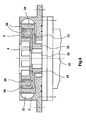
- FIG. 4 partially illustrated embodiment of a homogenizer according to the invention is designed in principle similar to the embodiment described above, so that in order to avoid repetition to the above descriptions, reference is made in full and only differences will be described below.
- the rotor 4 is driven by means of the drive shaft 30, toothed belt 44 and gear 48 and drive motor 52.
- the rotatable member 2 is driven by the outer drive shaft 36, timing belt 46, gear 50 and drive motor 54 independently of the rotor 4.
- the rotatable element 2 is provided with outer, attached to the base plate 32 pumping blades 34 which merge into a radially inwardly directed upper annular disc 82, from which axially in the direction of the base plate 24 projecting in the manner of a stator formed wing or stator elements 84 are formed , which are arranged between the pump blades 34 and the wings 28 and between the wings 26 and 28 and increase the shear effect.
- the stator elements 84 are rotatable together with the rotatable element 2 and the pump blades 34. Since the blades 84 are formed in the manner of a conventional stator and these are rotatable, can also be spoken of a "dynamic stator".
- the rotor 4 which can be driven by means of the drive shaft 30 has a plurality of webs 86 fastened to the base plate 24 and connected to a circular disk 88. From the circular disc 88 projecting axially inwardly projecting in the manner of a stator stator 90 from which are rotatable about the longitudinal axis 18.
- the rotatable element 2 which is coupled to the drive shaft 36, has blade-like blades 92 and outer pump blades 94.
- the stator elements 90 are arranged between pumping wheel 94 and the elements 92.
- FIG. 6 Further embodiment shown also referred to the above descriptions and explained below only the differences.
- the coupled to the drive shaft 30 rotor 6 is configured as in the previously with reference to FIG. 5 described embodiment.
- the rotatable by means of the drive shaft 36 element 6 is formed in the manner of a stator and has axially projecting from the base plate 24 stator elements 96.
Abstract
Description
Die Erfindung betrifft einen Homogenisator zum Homogenisieren fließfähiger Stoffe, mit einem in einem Gehäuse drehbar gelagerten und mittels einer Antriebseinrichtung antreibbaren Rotor.The invention relates to a homogenizer for homogenizing flowable substances, with a rotatably mounted in a housing and driven by a drive means rotor.
Derartige Homogenisatoren werden beispielsweise in der kosmetischen, pharmazeutischen oder chemischen Industrie bei der Herstellung von Cremes, Salben, Pasten oder dgl. eingesetzt. Der Homogenisator ist z. B. am tiefsten Punkt eines Behälters angeordnet und homogenisiert und/oder dispergiert den fließfähigen Stoff, indem der Rotor zusammen mit einem ortsfesten Stator Scherkräfte auf den Stoff aufbringt. Der Homogenisator könnte auch separat neben einem oder zwischen zwei Behälter(n) plaziert sein. Der homogenisierte Stoff kann entweder zurück in den Behälter oder zu einer Abfüllanlage gefördert werden.Such homogenizers are used, for example, in the cosmetic, pharmaceutical or chemical industry in the preparation of creams, ointments, pastes or the like. The homogenizer is z. B. arranged at the lowest point of a container and homogenized and / or dispersed the flowable material by the rotor together with a stationary stator shearing forces applied to the fabric. The homogenizer could also be placed separately next to or between two containers. The homogenised substance can either be returned to the container or to a bottling plant.
Die Homogenisierung läßt sich bei bekannten Homogenisatoren im wesentlichen durch Variation der Drehzahl des Rotors gegenüber dem festem Stator oder durch die konkrete Gestaltung des Rotors und/oder des Stators beeinflussen. Bei hohen Drehzahlen ist die Scherwirkung und auch die Förderwirkung des Homogenisators größer als bei niedrigen Drehzahlen. Ein Nachteil der bekannten Homogenisatoren besteht darin, dass die Scherwirkung und die Förderwirkung unmittelbar miteinander gekoppelt sind. Darüber hinaus ist es für die Erreichung hoher Scherwirkungen und Drehzahlen des Rotors notwendig, die Antriebseinrichtungen und Antriebsmotoren entsprechend aufwendig auszulegen.The homogenization can be influenced in known homogenizers essentially by varying the rotational speed of the rotor relative to the fixed stator or by the specific design of the rotor and / or the stator. At high speeds, the shearing action and the conveying action of the homogenizer is greater than at low speeds. A disadvantage of the known homogenizers is that the shearing action and the conveying action are coupled directly to each other. In addition, it is necessary for the achievement of high shear effects and speeds of the rotor to design the drive devices and drive motors accordingly consuming.
Ein weiterer Nachteil besteht darin, dass bei zu hoher Drehzahl des Motors die Scherwirkung so groß wird, dass der zu homogenisierende Stoff nachteilig beeinflusst oder eventuell sogar beschädigt werden kann.Another disadvantage is that at too high a speed of the engine, the shearing action is so great that the substance to be homogenized can be adversely affected or possibly even damaged.
Um dem Erfordernis der hohen Pumpleistung (Förderwirkung) gerecht werden zu können und gleichzeitig die Scherwirkung bei hohen Drehzahlen reduzieren zu können, wurden Homogenisatoren entwikelt, die eine axiale Verschiebung des Rotors relativ zum Stator ermöglichen, um die freien Strömungsquerschnitte (oder Spalte) zwischen den Flügeln des Rotors und des Stators zu erhöhen (vgl.
Weitere Homogenisatoren sind aus den folgenden Druckschriften aus dem Stand der Technik bekannt.Further homogenizers are known from the following documents from the prior art.
Die Patentschrift
Die Offenlegungsschrift
Aufgabe der vorliegenden Erfindung ist es, einen Homogenisator bereitzustellen, mit dem auf konstruktiv einfache Weise der Homogenisierungseffekt beeinflußbar ist und die Scherwirkung und die Pumpwirkung an die jeweiligen Erfordernisse anpassbar sind.The object of the present invention is to provide a homogenizer with which the homogenization effect can be influenced in a structurally simple manner and the shearing action and the pumping action can be adapted to the respective requirements.
Die Erfindung löst diese Aufgabe durch einen Homogenisator mit den Merkmalen des Anspruchs 1 sowie einem Verfahren gemäß Anspruch 11.The invention solves this problem by a homogenizer with the features of claim 1 and a method according to claim 11.
Die Vorteile der Erfindung bestehen im wesentlichen darin, dass durch das zusätzliche, separat und unabhängig vom Rotor antreibbare Element die Homogenisierung und Förderung auf vielfältige Weise beeinflusst und an die jeweiligen Produktionserfordernisse angepasst werden kann. Insbesondere durch Einstellung und Variation der Relativgeschwindigkeit des drehbaren Elements relativ zum Rotor lässt sich die Scherwirkung des Rotors und des drehbaren Elements auf dem Stoff einstellen. Das drehbare Element kann gleichsinnig oder gegenläufig zum Rotor angetrieben werden, um die Scherwirkung stufenlos innerhalb großer Bereiche variieren zu können. Darüber hinaus kann die Scherwirkung unabhängig von der Förderleistung (d. h. der Fördermenge des Stoffs) variiert werden. Beispielsweise kann die Pumpleistung konstant auf einem drehzahlabhängigen Wert gehalten werden, während die Scherwirkung bei Drehung des drehbaren Elements mit derselben oder annäherend derselben Drehgeschwindigkeit in der selben Drehrichtung gegen Null geht. Bei maximalen entgegengesetzen Drehgeschwindigkeiten ist die Scherwirkung maximal, wobei für dieselbe Scherwirkung eine wesentlich geringere absolute Drehgeschwindigkeit notwendig ist im Vergleich zu herkömmlichen Homogenisatoren. Dem gemäß können die Antriebe des erfindungsgemäßen Homogenisators für geringere Drehgeschwindigkeiten ausgelegt werden.The advantages of the invention consist essentially in the fact that can be influenced by the additional, separately and independently driven by the rotor element homogenization and promotion in a variety of ways and adapted to the respective production requirements. In particular, by adjusting and varying the relative speed of the rotatable member relative to the rotor, the shearing action of the rotor and the rotatable member on the fabric can be adjusted. The rotatable element can be driven in the same direction or in opposite directions to the rotor in order to be able to vary the shearing action steplessly within large areas. In addition, the shearing action can be varied independently of the delivery rate (i.e., the delivery rate of the substance). For example, the pumping power can be kept constant at a speed-dependent value, while the shearing action approaches zero at the same or approximately the same rotational speed in the same direction of rotation when the rotatable element rotates. At maximum opposing rotational speeds, the shearing action is maximal, and for the same shearing action, a substantially lower absolute rotational speed is necessary in comparison to conventional homogenizers. Accordingly, the drives of the homogenizer according to the invention can be designed for lower rotational speeds.
Gemäß einer Variante der Erfindung ist das drehbare Element als Pumprad mit mehreren Pumpschaufeln ausgebildet, um hohe Pumpleistungen erzielen zu können, während der Rotor im wesentlichen die Scherwirkung des Homogenisators erzeugt.According to a variant of the invention, the rotatable element is designed as a pumping wheel with a plurality of pumping blades, in order to be able to achieve high pumping powers, while the rotor essentially produces the shearing action of the homogenizer.
Bei einer alternativen Ausführungsform wird vorgeschlagen, dass das drehbare Element nach Art eines Stators oder eines Rotors mit Flügeln ausgebildet ist. Hierbei handelt es sich prinzipiell um einen Homogenisator mit einem "drehbaren Stator", um die zuvor beschriebene maximale Scherwirkung erzeugen zu können.In an alternative embodiment, it is proposed that the rotatable element is designed in the manner of a stator or a rotor with vanes. This is basically a homogenizer with a "rotatable stator" in order to produce the maximum shear described above.
Gemäß einer besonders bevorzugten Ausführungsform ist vorgesehen, dass das drehbare Element und der Rotor mit zwei koaxial zueinander angeordneten Antriebswellen zum Antreiben des drehbaren Elements bzw. des Rotors gekoppelt sind. Diese konstruktiv einfache Lösung ist platzsparend. Zur Reduzierung des Gewichts und der Materialkosten ist eine der beiden Antriebswellen vorzugsweise als Hohlwelle ausgebildet.According to a particularly preferred embodiment, it is provided that the rotatable element and the rotor are coupled to two coaxial drive shafts for driving the rotatable element or the rotor. This simple design solution saves space. To reduce the weight and the material costs, one of the two drive shafts is preferably designed as a hollow shaft.
Die Lagerung der Antriebswellen ist auf zweckmäßige Weise so gestaltet, dass die innere Antriebswelle mittels Wälzlagern in der äußeren Welle gelagert ist und die äußere Welle ihrerseits in einem Gehäuse gelagert ist.The storage of the drive shafts is expediently designed so that the inner drive shaft is mounted by means of rolling bearings in the outer shaft and the outer shaft is in turn mounted in a housing.
Um den Innenraum des Homogenisators gegenüber der Umgebung zuverlässig auch gegenüber hohen Druckdifferenzen und ggf. agressiven Medien abzudichten, wird gemäß einer Weiterbildung vorgeschlagen, dass mindestens eine Gleitringdichtung zur Abdichtung des Innenraums des Gehäuses des Homogenisators gegenüber der Umgebung vorgesehen ist. In den Innenräumen eines Rührwerkbehälters, an den ein erfindungsgemäßer Homogenisator anschliessbar ist, herrschen häufig Unter- oder Überdrücke, die so sicher beherrscht werden.In order to seal the interior of the homogenizer relative to the environment reliably against high pressure differences and possibly aggressive media, it is proposed according to a development that at least one mechanical seal is provided for sealing the interior of the housing of the homogenizer from the environment. In the interiors of an agitator container, to which a homogenizer according to the invention can be connected, there are often underpressures or overpressures which are controlled so reliably.
Eine konstruktiv einfache Gestaltung des Rotors und des drehbaren Elements sieht vor, dass der Rotor und/oder das drehbare Element eine mit der zugehörigen Antriebswelle gekoppelte Grundplatte aufweist, von der die Flügel axial abstehen, dass die Drehachsen der Antriebswellen im Betrieb im wesentlichen vertikal angeordnet ist und dass die Wellen mittels jeweils eines Zahnriemens angetrieben werden. Anstelle eines Zahnriemens könnten Ketten, Keilriemen, Reibräder, Zahnräder o. dgl. verwendet werden.A structurally simple design of the rotor and the rotatable element provides that the rotor and / or the rotatable element has a base plate coupled to the associated drive shaft, from which the wings protrude axially, that the axes of rotation of the drive shafts in operation is arranged substantially vertically and that the shafts are driven by means of a toothed belt. Instead of a toothed belt chains, V-belts, friction wheels, gears o. The like. Be used.
Die Scherwirkung und die Pumpwirkung kann auf einfache Weise dadurch variiert werden, dass die Antriebsmotoren des Rotors und des drehbaren Elements so steuerbar sind, dass Rotor und drehbares Element mit einstellbaren Relativgeschwindigkeiten gleichsinnig oder gegenläufig drehbar sind oder wahlweise entweder der Rotor oder das drehbare Element angetrieben werden, während das jeweils andere Bauteil still steht.The shearing action and the pumping action can be varied easily by controlling the drive motors of the rotor and of the rotatable element such that the rotor and the rotatable element have adjustable relative speeds can be rotated in the same direction or in opposite directions or selectively either the rotor or the rotatable element are driven while the other component is stationary.
Die Erfindung sieht vor dass das Gehäuse des Homogenisators eine Einlassöffnung, durch die fliessfähiges Material aus einem Behälter axial in den Innenraum einströmen kann, und eine Ausgangsöffnung aufweist, durch die der homogenisierte fließfähige Stoff im wesentlichen radial und/oder tangential aus dem Gehäuse ausströmt. Eine weitere bevorzugte Ausführungsform sieht vor, dass zwei mit der Ausgangsöffnung des Gehäuses kommunizierende Rückführungsleitungen vorgesehen sind, durch die in Abhängigkeit von der Stellung eines Stellventils der fließfähige Stoff an unterschiedliche Orten in den Behälter rückführbar ist. Auf diese Weise kann der Stoff beispielsweise oben in den Behälter oder nahe dem Homogenisator wieder rückgeführt werden, was für geringe Mengen eines zu homogenisierenden Stoffs zweckmäßig ist.The invention provides that the housing of the homogenizer has an inlet opening, through which flowable material from a container can flow axially into the interior space, and an outlet opening through which the homogenized flowable material flows out of the housing substantially radially and / or tangentially. A further preferred embodiment provides that two return lines communicating with the outlet opening of the housing are provided, through which the flowable substance can be returned to different locations in the container, depending on the position of a control valve. In this way, the substance, for example, top recycled into the container or near the homogenizer, which is useful for small amounts of a substance to be homogenized.
Die Scherwirkung lässt sich dadurch weiter optimieren, dass zusätzliche, ortsfeste Stator-Verzahnungen an einem Gehäuses des Homogenisators angeordnet sind.The shearing effect can be further optimized by arranging additional, stationary stator toothings on a housing of the homogenizer.
Die Erfindung ist nachstehend anhand von Ausführungsbeispielen unter Bezugnahme auf die beiliegenden Zeichnungen beschrieben. Es zeigen:
-
Figur 1 einen erfindungsgemäßen Homogenisator gemäß einem ersten Ausführungsbeispiel in einer Seitenansicht; -
Figur 2Figur 1 ; -
Figur 3 eine weitere Teilschnittdarstellung des Homogenisators gemäßFigur 1 ; -
Figur 4 -
Figur 5 ein Abschnitt eines weiteren Homogenisators gemäß eines dritten Ausführungsbeispiels in einer Teilschnittdarstellung; -
Figur 6
-
FIG. 1 a homogenizer according to the invention according to a first embodiment in a side view; -
FIG. 2 a partial sectional view of the homogenizer according toFIG. 1 ; -
FIG. 3 a further partial sectional view of the homogenizer according toFIG. 1 ; -
FIG. 4 a section of another homogenizer according to a second embodiment in a partial sectional view; -
FIG. 5 a section of another homogenizer according to a third embodiment in a partial sectional view; -
FIG. 6 a section of another homogenizer according to a fourth embodiment in a partial sectional view;
Der in den
Der Rotor 4 weist eine kreisförmige Grundplatte 24 (vgl.
Das drehbare Element 6 ist im Ausführungsbeispiel als Pumprad mit mehreren axial von einer weiteren scheibenförmigen Grundplatte 32 abstehenden Pumpschaufel 34 ausgebildet, die entlang einem relativ zu den Schaufeln 26, 28 konzentrischen Kreis verlaufen und in an sich bekannter Weise so gestaltet sind, dass der fließfähige Stoff mit relativ hoher Pumpleistung durch den Homogenisator in den Kanal 20 gefördert wird. Die Grundplatte 32 ist einstückig mit einer konzentrisch zu der Antriebswelle 30 angeordneten äußeren Antriebswelle 36, die als Hohlwelle ausgebildet ist, gekoppelt. Die Grundplatten 24 und 32 sind im wesentlichen parallel zueinander angeordnet.The
Zur Erhöhung des Homogenisierungs- und/oder Dispersionseffekts des Homogenisators sind an dem Gehäuse 2 mehrere axial nach innen in den Innenraum 16 hineinragende, einen Stator 38 bildende Statorelemente oder -ringe vorgesehen, die mehrstufig, im Ausführungsbeispiel zweistufig ausgebildet sind. Innere Statorelemente sind in radialer Richtung gesehen zwischen den Schaufeln 26 bzw. 28 angeordnet und weitere Statorelemente sind zwischen den Schaufeln 28 und den Pumpschaufeln 34 des drehbaren Elements 6 plaziert.To increase the homogenization and / or dispersion effect of the homogenizer, a plurality of axially inwardly into the interior 16 protruding, a
Die Antriebseinrichtung 8, mit der der Rotor 4 und das drehbare Elements 6 unabhängig voneinander antreibbar sind, ist nachfolgend anhand der
Die äußere Antriebswelle 36 ist mittels zweier Lager 60, 62, bei denen es sich um Wälz- oder Gleitlager handelt, in einem Gehäuse 64 gelagert, welches an das Gehäuse 2 des Homogenisators angeflanscht ist. Die Grundplatte 32 des drehbaren Elements 6 mit seinen Pumpschaufeln 34 ist mit einem oberen Endabschnitt der Antriebswelle 36 mit Hilfe von Schrauben 66 drehstarr verbunden; selbstverständlich könnten anstelle der Schrauben andere Befestigungsmittel oder eine einstückige Bauweise eingesetzt werden. Im unteren Bereich ist das Gehäuse 64 mit einem Deckel 68 verschlossen, der gleichzeitig das Lager 62 festlegt.The
Die innere, den Rotor 4 antreibende Antriebswelle 30 ist mittels zweier Lager 70, 72 drehbar in der Antriebswelle 36 gelagert. Sämtliche Lager 62, 64, 70, 72 sind mit ausreichend Schmiermittel gefüllt ("selbstschmierend") und mit Hilfe von Sicherungsringen und Hülsen an den vorgegebenen Positionen festgelegt.The inner, the
Zur Abdichtung des Innenraums 16 des Homogenisators gegenüber der äusseren Umgebung sind zwei Gleitringdichtungen 78, 80 mit jeweils vier Gleitringen vorgesehen. Alternativ könnten andere Wellenabdichtungen, etwa Lippendichtringe o. dgl. eingesetzt werden. Ein oberer Gleitring der Gleitringdichtung 78 ist fest mit dem Gehäuse 2 verbunden, während ein unterer Gleitring an der Antriebswelle 36 befestigt ist und mit dieser rotiert, so dass fließfähiger Stoff nicht aus dem Innenraum 16 in den Innenraum des Gehäuses 62 strömen kann. Ein - in
Das in
Das weitere, anhand von
Schließlich wird hinsichtlich des in
Claims (11)
- An homogenizer for the homogenization of flowable substances, having a rotor (4) which is rotatably mounted in a housing (2) and which is driveable by means of a drive device (8),
wherein the housing (2) of the homogenizer has an inlet opening (14) though which flowable material can flow into the interior space (16) in an axial manner and an outlet opening through which the homogenized, flowable substance flows out of the housing (2) in a substantially radial and/or tangential manner,
wherein there is provided an element (6) for the homogenization and/or conveying of the flowable substance, which element is rotatably mounted in the housing (2) and is drivable independently of the rotor by means of a drive device (8),
characterised in that the rotatable element (6) is drivable in the same direction as or the opposite direction to the rotor (4), and in that the driving motors (52), (54) of the rotor (4) and the rotatable element (6) are controllable in such a manner that rotor (4) and rotatable element (6) are rotatable in the same direction or in opposite directions at adjustable relative speeds or selectively either the rotor (4) or the rotatable element (6) is driven, while the other part in each case is at rest. - An homogenizer according to claim [1], characterised in that [the] rotatable element (6) is in the form of a pump wheel with a plurality of pump blades (34).
- An homogenizer according to claim 2, characterised in that the rotatable element (6) is designed in the manner of a stator or a rotor with vanes (84).
- An homogenizer according to any one of the preceding claims, characterised in that at least one shaft seal, preferably a slide ring seal (78), (80), is provided to seal the interior space (16) of the housing (2) of the homogenizer with respect to the surroundings.
- An homogenizer according to any one of the preceding claims, characterised in that the rotatable element (6) and the rotor (4) are coupled to two drive shafts (36), (30), arranged coaxial with one another, to drive the rotatable element (6) and the rotor (4) respectively, at least one of the two drive shafts (30), (36) is in the form of a hollow shaft, the inner drive shaft (30) is mounted in the outer drive shaft (36) by means of rolling bearings and the outer drive shaft (36) is for its part mounted in a housing 64.
- An homogenizer according to any one of the preceding claims, characterised in that the rotor (4) and/or the rotatable element (6) has/have a base plate (24), (32) coupled to the associated drive shaft (30), (36), the vanes (34), (38) projecting axially from the base plate (24), (32), in that the axes of rotation of the drive shafts (30), (36) is[sic] arranged substantially vertically in operation and in that the drive shafts are driven by means of a respective toothed belt (44), (46), V-belt or chain.
- An homogenizer according to any one of the preceding claims, characterised in that the driving motors (52), (54) of the rotor (4) and the rotatable element (6) are controllable in such a manner that rotor (4) and rotatable element (6) in each case rotate in both rotational directions.
- An homogenizer according to claim 7, characterised in that two return lines (22) communicating with the outlet opening of the housing are provided, through which the flowable substance is returnable at different sites into a container dependent on the position of an adjusting valve.
- An homogenizer according to any one of the preceding claims, characterised in that additional, fixed stator toothings (38) are arranged on the housing (2) of the homogenizer.
- An homogenizer according to any one of the preceding claims, characterised in that a drive shaft (30), (36) of the rotor (4) and/or the rotatable element (6) is driven directly by means of a driving motor (52, 54).
- A method of homogenizing flowable substances by means of a homogenizer having a rotor (4) which is rotatably mounted in a housing (2) and which is drivable by means of a drive device (8), wherein the housing (2) of the homogenizer has an inlet opening (14) though which flowable material flows into the interior space (16) in an axial manner and an outlet opening through which the homogenized, flowable substance flows out of the housing (2) in a substantially radial and/or tangential manner,
in which the flowable substance is homogenized and/or conveyed by means of an element (6) which is rotatably mounted in the housing (2) and is drivable independently of the rotor (4) by means of a drive device (6),
wherein the rotatable element (6) is drivable in the same direction as or the opposite direction to the rotor (4),
characterised in that- driving motors (52), (54) of the rotor (4) and the rotatable element (6) are controllable in such a manner that rotor (4) and rotatable element (6) are rotatable in the same direction or in opposite directions at adjustable relative speeds, in order to be able to vary the shearing effect on the substance in a stepless manner,- or in that selectively either the rotor (4) or the rotatable element (6) is driven, while the other part in each case is at rest.
Applications Claiming Priority (2)
| Application Number | Priority Date | Filing Date | Title |
|---|---|---|---|
| DE20002920U DE20002920U1 (en) | 2000-02-18 | 2000-02-18 | Homogenizer |
| EP01103854A EP1125625B1 (en) | 2000-02-18 | 2001-02-16 | Homogenising device |
Related Parent Applications (1)
| Application Number | Title | Priority Date | Filing Date |
|---|---|---|---|
| EP01103854A Division EP1125625B1 (en) | 2000-02-18 | 2001-02-16 | Homogenising device |
Publications (2)
| Publication Number | Publication Date |
|---|---|
| EP1825907A1 EP1825907A1 (en) | 2007-08-29 |
| EP1825907B1 true EP1825907B1 (en) | 2012-10-03 |
Family
ID=7937511
Family Applications (2)
| Application Number | Title | Priority Date | Filing Date |
|---|---|---|---|
| EP07106354A Expired - Lifetime EP1825907B1 (en) | 2000-02-18 | 2001-02-16 | Homogenising device |
| EP01103854A Expired - Lifetime EP1125625B1 (en) | 2000-02-18 | 2001-02-16 | Homogenising device |
Family Applications After (1)
| Application Number | Title | Priority Date | Filing Date |
|---|---|---|---|
| EP01103854A Expired - Lifetime EP1125625B1 (en) | 2000-02-18 | 2001-02-16 | Homogenising device |
Country Status (5)
| Country | Link |
|---|---|
| US (1) | US6866412B2 (en) |
| EP (2) | EP1825907B1 (en) |
| AT (1) | ATE359859T1 (en) |
| DE (2) | DE20002920U1 (en) |
| ES (1) | ES2286048T3 (en) |
Families Citing this family (18)
| Publication number | Priority date | Publication date | Assignee | Title |
|---|---|---|---|---|
| SE9804442D0 (en) * | 1998-12-21 | 1998-12-21 | Global Powder Ab | Device and method for continuous mixing |
| US6648500B2 (en) * | 1999-04-13 | 2003-11-18 | International Process Equipment And Technology, Inc. | Rotary pulsation device |
| DE10023694C2 (en) * | 2000-05-16 | 2002-04-04 | Ystral Gmbh Maschb & Processte | Devices for mixing fabrics |
| EP1331988B1 (en) * | 2000-11-10 | 2006-06-14 | Maelstrom Advanced Process Technologies Ltd | Dynamic mixer |
| DE10320739B3 (en) | 2003-05-09 | 2004-10-21 | Ika - Werke Gmbh & Co. Kg | Device for dispersing and/or homogenizing pumpable material mixtures comprises a pump arranged in the feed direction of the material at a distance from a dispersing and/or homogenizing tool and in front of the opening of a feed line |
| DE102004025281B4 (en) * | 2004-05-19 | 2008-09-04 | Henkel Ag & Co. Kgaa | Process for the preparation of agents for coloring keratinic fibers |
| SE527867C2 (en) * | 2004-11-12 | 2006-06-27 | Bjoern Gudmunsson | Cooling installation |
| DE102005017075A1 (en) * | 2005-04-13 | 2006-10-19 | Ekato Unimix Gmbh | Device for homogenizing and / or dispersing flowable substances |
| ATE437694T1 (en) * | 2006-03-29 | 2009-08-15 | Hebold Mixing & More Gmbh | HOMOGENIZER |
| DE102007016445A1 (en) * | 2007-04-04 | 2008-10-09 | Beiersdorf Ag | Preparing fluid cationic emulsion, useful e.g. as an sun protective agent and insect repellent, comprises emulsifying water phase/fat phase comprising cationic emulsifying agent, and subsequently homogenizing and cooling |
| US7887862B2 (en) * | 2007-10-10 | 2011-02-15 | Industrias Centli S.A. De C.V. | Method and apparatus for separating, purifying, promoting interaction and improving combustion |
| DE102009047777A1 (en) | 2009-09-30 | 2011-04-07 | Azo Holding Gmbh | Homogenizer and homogenizer with such a homogenizer |
| FR2952641B1 (en) * | 2009-11-18 | 2012-01-13 | Lfb Biomedicaments | PROCESS FOR TREATING BLOOD PLASMA COMPRISING A DISPERSION WASH STEP |
| JP2011147936A (en) * | 2010-09-29 | 2011-08-04 | Sintokogio Ltd | Shearing type dispersing device, circulation type dispersing system and circulation type dispersing method |
| KR101780329B1 (en) * | 2015-05-06 | 2017-09-20 | 주식회사 케이엔에스컴퍼니 | A system structure of impeller for dispersion-emulsion apparatus based on dual rotator |
| DE202016000169U1 (en) | 2016-01-14 | 2017-04-20 | Symex Gmbh & Co. Kg | Pumping and / or mixing device for conveying, homogenizing and / or dispersing flowable products |
| KR101992949B1 (en) * | 2017-09-21 | 2019-06-26 | 주식회사 우원 | Raw material homogenization equipment with surface temperature sensor |
| DE202018102804U1 (en) | 2018-05-18 | 2019-08-22 | Symex Gmbh & Co. Kg | Device for homogenizing flowable substances |
Family Cites Families (75)
| Publication number | Priority date | Publication date | Assignee | Title |
|---|---|---|---|---|
| US204124A (en) * | 1878-05-28 | Improvement in churns | ||
| DE183671C (en) | ||||
| FR606508A (en) | 1924-11-19 | 1926-06-15 | Improvements to centrifugal devices for emulsifying, mixing or spraying any liquid, semi-liquid or dry substance | |
| US1624037A (en) * | 1925-04-30 | 1927-04-12 | Colloidal Equipment Corp | Apparatus for deflocculating and emulsifying |
| DE553055C (en) | 1929-10-08 | 1932-06-21 | Paul Griese | Centrifugal mill |
| GB665981A (en) * | 1946-10-04 | 1952-02-06 | Robert John Jay | Improvements in or relating to methods of and apparatus for emulsifying liquids |
| US2685436A (en) | 1950-08-31 | 1954-08-03 | Goodrich Co B F | Apparatus for foaming liquids |
| US2723110A (en) * | 1953-12-21 | 1955-11-08 | Lowell J Collins | Sanitary bearing and shaft combination |
| CH389577A (en) | 1960-06-24 | 1965-03-31 | Physik Chem Forschungsinstitut | Mixing and dispersing device |
| US3224744A (en) * | 1962-03-19 | 1965-12-21 | Day J H Co | Vertical mixer construction |
| FR1455028A (en) | 1963-12-23 | 1966-04-01 | Method and apparatus for the instantaneous working of floury materials, applicable in particular to the instantaneous preparation of treated plaster pastes | |
| US3271194A (en) * | 1964-01-27 | 1966-09-06 | Yokohama Seito Kabushiki Kaish | Solidification of saccharide solutions |
| US3308171A (en) * | 1964-07-17 | 1967-03-07 | Yokohama Seito Kabushiki Kaish | Method for producing granular or powdery sorbitol from sorbitol solution |
| US3580546A (en) * | 1968-09-05 | 1971-05-25 | Kaydon Technical Enterprises L | Device for mixing and proportioning liquids |
| US3731800A (en) * | 1970-11-27 | 1973-05-08 | Polaroid Corp | Counter-current centrifugal device and use |
| US3845938A (en) * | 1972-09-27 | 1974-11-05 | G Schold | Apparatus for dispersing finely divided solid particles in a liquid vehicle |
| DK133269C (en) | 1974-03-26 | 1976-09-20 | Rotostat Is | MIXING UNIT FOR MIXING AND PROCESSING OF LIQUID MATERIALS |
| US3929318A (en) | 1974-12-09 | 1975-12-30 | Exxon Research Engineering Co | Static mixers for viscous material |
| US4019722A (en) * | 1975-11-28 | 1977-04-26 | Littleford Bros. Inc. | High intensity mixer utilizing a single speed motor |
| US4198168A (en) | 1978-04-12 | 1980-04-15 | Liquid Control Incorporated | Phase blending static mixing process and apparatus |
| US4222671A (en) * | 1978-09-05 | 1980-09-16 | Gilmore Oscar Patrick | Static mixer |
| EP0013547A1 (en) | 1978-12-21 | 1980-07-23 | WAROP Industrie Aktiengesellschaft | Process for the production of stable aqueous emulsions or suspensions of combustion or heating fuel |
| AT363862B (en) | 1979-02-12 | 1981-09-10 | Central Intertrade Finance | METHOD FOR ACTIVATING WATER, FOR THE PURPOSE OF PROMOTING GROWTH AND DISINTEREGRATOR, AND DEVICE FOR IMPLEMENTING THE METHOD |
| CH642564A5 (en) | 1979-10-26 | 1984-04-30 | Sulzer Ag | STATIC MIXING DEVICE. |
| GB2077618A (en) * | 1980-06-13 | 1981-12-23 | Rtl Contactor Holding Sa | Contactor |
| DE3027567A1 (en) * | 1980-07-21 | 1982-02-25 | Dieter 6570 Kirn Kupka | AGITATOR WITH TWO AGITATING ORGANS DRIVED AROUND THE SAME GEOMETRIC AXIS |
| AT375417B (en) * | 1980-11-25 | 1984-08-10 | Escher Wyss Gmbh | DISPERSING DEVICE FOR THE TREATMENT OF WASTE PAPER |
| DE3212642A1 (en) | 1981-04-14 | 1982-11-18 | Desro Patentverwertungs Ag | METHOD FOR PREPARING FUELS OR FUEL COMPONENTS, FUELS PREPARED BY THE METHOD AND DEVICE FOR IMPLEMENTING THE METHOD |
| DD205076A1 (en) | 1981-09-04 | 1983-12-21 | Klaus Hoppe | CONTACTING DEVICE FOR CONTINUOUS STATIC MIXING AND DISTRIBUTION OF FLUIDABLE SUBSTANCES |
| JPS5939174B2 (en) | 1982-02-01 | 1984-09-21 | 名友産業株式会社 | fluid mixing device |
| DE8215535U1 (en) | 1982-05-28 | 1985-07-11 | Janke & Kunkel GmbH & Co KG Ika - Werk, 7813 Staufen | Dispersing device |
| DE3220092A1 (en) | 1982-05-28 | 1983-12-01 | Janke & Kunkel GmbH & Co KG Ika - Werk, 7813 Staufen | DISPERSING DEVICE |
| DE8414202U1 (en) | 1984-05-10 | 1987-07-23 | Haagen & Rinau Mischtechnik Gmbh, 2800 Bremen, De | |
| DE3417242A1 (en) | 1984-05-10 | 1985-11-14 | Haagen & Rinau | Homogenising appliance |
| US4582432A (en) | 1984-12-20 | 1986-04-15 | Usm Corporation | Rotary processors and methods for mixing low viscosity liquids with viscous materials |
| JPS61268344A (en) * | 1985-01-22 | 1986-11-27 | Funken:Kk | Method and apparatus for continuous kneading of powder such as fine powdery coal of oil coke in order to prepare slurry |
| CH665959A5 (en) | 1985-04-03 | 1988-06-30 | Miteco Ag | DEVICE FOR MIXING AT LEAST ONE FLOW MEDIUM. |
| DE3520040A1 (en) * | 1985-06-04 | 1986-12-04 | Herfeld, Friedrich Walter, Dr., 5982 Neuenrade | DEVICE FOR MIXING GOODS |
| US4889428A (en) * | 1985-07-29 | 1989-12-26 | Concrete Technology Corporation | Rotary mill |
| JPS631430A (en) * | 1986-06-20 | 1988-01-06 | Ishiyama Bunyo | High-speed dissolving and wetting method for powder and grain materials |
| DE3715331A1 (en) | 1987-05-08 | 1988-12-01 | Berents Gmbh & Co Kg A | HOMOGENIZER FOR THE PRODUCTION OF FLOWABLE PRODUCTS |
| FR2620044B1 (en) * | 1987-09-08 | 1989-12-22 | Pillon Francis | PROCESS AND DEVICE FOR SPREADING OR MIXING POWDERS BY DEPOSITION OF AIR-SUSPENDED PARTICLES |
| DD293059A5 (en) | 1987-12-11 | 1991-08-22 | ���������������������k | DEVICE FOR HOMOGENIZING SUBSTANCES WITH DIFFERENT AGGREGATE EXPOSURES |
| US4848920A (en) * | 1988-02-26 | 1989-07-18 | Husky Injection Molding Systems Ltd. | Static mixer |
| DE3810609A1 (en) * | 1988-03-29 | 1989-10-12 | Fryma Masch Ag | DEVICE FOR MIXING AND HOMOGENIZING FLOWABLE PRODUCTS |
| JP2646111B2 (en) * | 1988-06-27 | 1997-08-25 | 日本コム株式会社 | Continuous flow stirrer |
| JPH0265743U (en) | 1988-11-04 | 1990-05-17 | ||
| US4878677A (en) * | 1988-12-15 | 1989-11-07 | Hydrochem Developments Ltd. | Shut off seal about a shaft of a device having a side entry into a tank |
| DD280048A1 (en) | 1989-02-24 | 1990-06-27 | Univ Halle Wittenberg | DEVICE FOR IMPLEMENTING SOLIDS IN OR WITH LIQUIDS |
| FI895593A (en) | 1989-11-22 | 1991-05-23 | Flowcon Oy | ANORDIN I SYNNERHET FOER BEHANDLING AV KRAEMER OCH PASTOR. |
| US5309403A (en) * | 1991-07-10 | 1994-05-03 | Complete Automation, Inc. | Modular continuous flow paint delivery system |
| DE4209527A1 (en) | 1992-03-24 | 1993-09-30 | Dorr Oliver Deutschland | Emulsion homogeniser improving fineness of grains - has two facing contra-rotating truncated cone rotors and reduce droplet size without increase in machine complexity |
| US5253937A (en) * | 1992-06-29 | 1993-10-19 | Nalco Chemical Company | Method and apparatus for dispersing or dissolving particles of a pelletized material in a liquid |
| DK150692A (en) * | 1992-12-16 | 1994-06-17 | Niro Holding As | Automatic manure sprinkler |
| DE9305553U1 (en) | 1993-04-15 | 1993-05-19 | Koruma Maschinenbau Gmbh, 7844 Neuenburg, De | |
| US5460444A (en) * | 1993-04-28 | 1995-10-24 | Howorka; Franz | Apparatus for the treatment of solid, liquid and/or gaseous materials |
| ES2141143T3 (en) | 1993-10-05 | 2000-03-16 | Sulzer Chemtech Ag | DEVICE FOR HOMOGENIZING VERY VISCOUS LIQUIDS. |
| DE59409323D1 (en) | 1994-03-09 | 2000-06-08 | Sulzer Chemtech Ag Winterthur | Flat structure element and packing formed from it |
| DE4433039B4 (en) * | 1994-09-16 | 2006-11-16 | Richard Frisse Gmbh | Devices for processing dispersions |
| DE19614295A1 (en) | 1995-04-21 | 1996-10-24 | Friedrich Dr Ing Vock | Method and device for wet grinding and dispersing solid particles in liquids |
| US5975440A (en) | 1995-04-21 | 1999-11-02 | Watson; William Ferguson | Mixing |
| ES2155509T3 (en) | 1995-06-21 | 2001-05-16 | Sulzer Chemtech Ag | TUBE SHAPED BODY MIXER. |
| DE59505850D1 (en) | 1995-08-30 | 1999-06-10 | Sulzer Chemtech Ag | Static mixer for viscous fluids |
| BE1009675A3 (en) * | 1995-09-27 | 1997-06-03 | Haegeman J H | LIQUID TREATMENT APPARATUS. |
| JP3595892B2 (en) * | 1995-12-20 | 2004-12-02 | 有限会社勝製作所 | Stirring device for synthetic resin raw materials |
| JP3127115B2 (en) | 1996-02-29 | 2001-01-22 | 東京日進ジャバラ株式会社 | Static mixing device |
| DE29608713U1 (en) | 1996-05-14 | 1996-08-08 | Wittek Axel | Dispersing device |
| JPH10370A (en) * | 1996-06-13 | 1998-01-06 | Kansai Matetsuku Kk | Pulverizing pin type pulverizer |
| ATE195889T1 (en) | 1996-07-05 | 2000-09-15 | Sulzer Chemtech Ag | STATIC MIXER |
| WO1998058730A1 (en) | 1997-06-20 | 1998-12-30 | Kankyou Kagaku Kougyou Kabushiki Kaisya | Static fluid mixer |
| DE19837671A1 (en) | 1998-08-20 | 2000-02-24 | Bayer Ag | Static mixer |
| DE29822149U1 (en) | 1998-08-25 | 1999-04-08 | Vakumix Ruehr Und Homogenisier | Homogenizer with protective toothing |
| DE10005457A1 (en) | 2000-02-08 | 2001-08-09 | Bayer Ag | Static mixer |
| DE10103425A1 (en) | 2001-01-26 | 2002-08-01 | Basf Ag | Mixing method, to mix or homogenize microscopic or macroscopic flows, has parallel flow planes with serpentine flow paths and separation plane with passage openings, to connect flows by alternating eddy part-flows |
| EP1437173B1 (en) | 2002-12-13 | 2006-01-11 | Sulzer Chemtech AG | Static mixer for highly viscous media |
-
2000
- 2000-02-18 DE DE20002920U patent/DE20002920U1/en not_active Expired - Lifetime
-
2001
- 2001-02-15 US US09/784,637 patent/US6866412B2/en not_active Expired - Lifetime
- 2001-02-16 EP EP07106354A patent/EP1825907B1/en not_active Expired - Lifetime
- 2001-02-16 ES ES01103854T patent/ES2286048T3/en not_active Expired - Lifetime
- 2001-02-16 EP EP01103854A patent/EP1125625B1/en not_active Expired - Lifetime
- 2001-02-16 DE DE50112352T patent/DE50112352D1/en not_active Expired - Lifetime
- 2001-02-16 AT AT01103854T patent/ATE359859T1/en active
Also Published As
| Publication number | Publication date |
|---|---|
| DE20002920U1 (en) | 2000-04-20 |
| EP1125625A3 (en) | 2002-01-30 |
| EP1125625A2 (en) | 2001-08-22 |
| ATE359859T1 (en) | 2007-05-15 |
| US20010036125A1 (en) | 2001-11-01 |
| ES2286048T3 (en) | 2007-12-01 |
| US6866412B2 (en) | 2005-03-15 |
| DE50112352D1 (en) | 2007-05-31 |
| EP1125625B1 (en) | 2007-04-18 |
| EP1825907A1 (en) | 2007-08-29 |
Similar Documents
| Publication | Publication Date | Title |
|---|---|---|
| EP1825907B1 (en) | Homogenising device | |
| EP0802879B1 (en) | Device for metering bulk material | |
| EP3202489B1 (en) | Device for homogenizing and/or dispersing flowable products | |
| EP2219917B1 (en) | Vacuum pump | |
| EP3894706A1 (en) | Lobe pump with inner bearing | |
| DE2643560C2 (en) | Stirrer | |
| EP1470856A1 (en) | Stirrer for mixing, homogenising and dispersing | |
| EP0946303B1 (en) | Comminution machine with an emulsifier | |
| EP0645179B1 (en) | Grinding mill and mixer containing said grinding mill | |
| DE4337761A1 (en) | Rotating machine part, esp. rotor of cycloidal ship propeller - has central introduction point on rotor or housing and back conduits for further heat transmission medium | |
| EP2305370A1 (en) | Homogeniser and homogenising device with such a homogeniser | |
| EP0801974B1 (en) | Device for homogenizing and/or dispersing a flowable material | |
| DE2901638B1 (en) | Centrifugal pump for liquids mixed with solids | |
| DE2219352A1 (en) | Continuous horizontal fixed drum mixer - for chips, fibres or powder, with liq | |
| EP3572145B1 (en) | Device and method for homogenisation of flowable material | |
| EP0832682A1 (en) | Apparatus for homogenizing and dispersing liquid phases | |
| EP0740953B1 (en) | Device for grinding and mixing masses | |
| EP0930093A2 (en) | Apparatus for stirring a mixture as well as use of apparatus | |
| EP2001581B1 (en) | Homogenizer | |
| DE102004055611B4 (en) | Device, in particular for driving a lifting movement and a pivoting movement exporting institution | |
| DE3243169A1 (en) | Hydrokinetic machine | |
| DE1461014C (en) | Disk mill for lumpy vegetable material | |
| DE3150569A1 (en) | Vane cell pump | |
| DE1813215A1 (en) | Device for transmitting a rotary movement from a drive to an output located at a distance from this | |
| DE1247128B (en) | Friction disk mills for grinding, dissolving, mixing, emulsifying or the like of mixtures of substances consisting of solid and liquid components |
Legal Events
| Date | Code | Title | Description |
|---|---|---|---|
| PUAI | Public reference made under article 153(3) epc to a published international application that has entered the european phase |
Free format text: ORIGINAL CODE: 0009012 |
|
| AC | Divisional application: reference to earlier application |
Ref document number: 1125625 Country of ref document: EP Kind code of ref document: P |
|
| AK | Designated contracting states |
Kind code of ref document: A1 Designated state(s): AT BE CH CY DE DK ES FI FR GB GR IE IT LI LU MC NL PT SE TR |
|
| 17P | Request for examination filed |
Effective date: 20080218 |
|
| 17Q | First examination report despatched |
Effective date: 20080331 |
|
| AKX | Designation fees paid |
Designated state(s): AT BE CH CY DE DK ES FI FR GB GR IE IT LI LU MC NL PT SE TR |
|
| GRAP | Despatch of communication of intention to grant a patent |
Free format text: ORIGINAL CODE: EPIDOSNIGR1 |
|
| GRAS | Grant fee paid |
Free format text: ORIGINAL CODE: EPIDOSNIGR3 |
|
| GRAA | (expected) grant |
Free format text: ORIGINAL CODE: 0009210 |
|
| AC | Divisional application: reference to earlier application |
Ref document number: 1125625 Country of ref document: EP Kind code of ref document: P |
|
| AK | Designated contracting states |
Kind code of ref document: B1 Designated state(s): AT BE CH CY DE DK ES FI FR GB GR IE IT LI LU MC NL PT SE TR |
|
| REG | Reference to a national code |
Ref country code: GB Ref legal event code: FG4D Free format text: NOT ENGLISH |
|
| REG | Reference to a national code |
Ref country code: CH Ref legal event code: NV Representative=s name: E. BLUM & CO. AG PATENT- UND MARKENANWAELTE VSP Ref country code: CH Ref legal event code: EP Ref country code: AT Ref legal event code: REF Ref document number: 577708 Country of ref document: AT Kind code of ref document: T Effective date: 20121015 |
|
| REG | Reference to a national code |
Ref country code: IE Ref legal event code: FG4D Free format text: LANGUAGE OF EP DOCUMENT: GERMAN |
|
| REG | Reference to a national code |
Ref country code: DE Ref legal event code: R096 Ref document number: 50116182 Country of ref document: DE Effective date: 20121129 |
|
| REG | Reference to a national code |
Ref country code: NL Ref legal event code: VDEP Effective date: 20121003 |
|
| PG25 | Lapsed in a contracting state [announced via postgrant information from national office to epo] |
Ref country code: FI Free format text: LAPSE BECAUSE OF FAILURE TO SUBMIT A TRANSLATION OF THE DESCRIPTION OR TO PAY THE FEE WITHIN THE PRESCRIBED TIME-LIMIT Effective date: 20121003 Ref country code: SE Free format text: LAPSE BECAUSE OF FAILURE TO SUBMIT A TRANSLATION OF THE DESCRIPTION OR TO PAY THE FEE WITHIN THE PRESCRIBED TIME-LIMIT Effective date: 20121003 Ref country code: NL Free format text: LAPSE BECAUSE OF FAILURE TO SUBMIT A TRANSLATION OF THE DESCRIPTION OR TO PAY THE FEE WITHIN THE PRESCRIBED TIME-LIMIT Effective date: 20121003 |
|
| PG25 | Lapsed in a contracting state [announced via postgrant information from national office to epo] |
Ref country code: PT Free format text: LAPSE BECAUSE OF FAILURE TO SUBMIT A TRANSLATION OF THE DESCRIPTION OR TO PAY THE FEE WITHIN THE PRESCRIBED TIME-LIMIT Effective date: 20130204 Ref country code: CY Free format text: LAPSE BECAUSE OF FAILURE TO SUBMIT A TRANSLATION OF THE DESCRIPTION OR TO PAY THE FEE WITHIN THE PRESCRIBED TIME-LIMIT Effective date: 20121003 Ref country code: GR Free format text: LAPSE BECAUSE OF FAILURE TO SUBMIT A TRANSLATION OF THE DESCRIPTION OR TO PAY THE FEE WITHIN THE PRESCRIBED TIME-LIMIT Effective date: 20130104 |
|
| PG25 | Lapsed in a contracting state [announced via postgrant information from national office to epo] |
Ref country code: DK Free format text: LAPSE BECAUSE OF FAILURE TO SUBMIT A TRANSLATION OF THE DESCRIPTION OR TO PAY THE FEE WITHIN THE PRESCRIBED TIME-LIMIT Effective date: 20121003 |
|
| PLBE | No opposition filed within time limit |
Free format text: ORIGINAL CODE: 0009261 |
|
| STAA | Information on the status of an ep patent application or granted ep patent |
Free format text: STATUS: NO OPPOSITION FILED WITHIN TIME LIMIT |
|
| BERE | Be: lapsed |
Owner name: SYMEX G.M.B.H. & CO. KG Effective date: 20130228 |
|
| 26N | No opposition filed |
Effective date: 20130704 |
|
| PG25 | Lapsed in a contracting state [announced via postgrant information from national office to epo] |
Ref country code: MC Free format text: LAPSE BECAUSE OF NON-PAYMENT OF DUE FEES Effective date: 20130228 |
|
| PG25 | Lapsed in a contracting state [announced via postgrant information from national office to epo] |
Ref country code: ES Free format text: LAPSE BECAUSE OF FAILURE TO SUBMIT A TRANSLATION OF THE DESCRIPTION OR TO PAY THE FEE WITHIN THE PRESCRIBED TIME-LIMIT Effective date: 20130114 |
|
| REG | Reference to a national code |
Ref country code: DE Ref legal event code: R097 Ref document number: 50116182 Country of ref document: DE Effective date: 20130704 |
|
| REG | Reference to a national code |
Ref country code: IE Ref legal event code: MM4A |
|
| PG25 | Lapsed in a contracting state [announced via postgrant information from national office to epo] |
Ref country code: BE Free format text: LAPSE BECAUSE OF NON-PAYMENT OF DUE FEES Effective date: 20130228 Ref country code: IE Free format text: LAPSE BECAUSE OF NON-PAYMENT OF DUE FEES Effective date: 20130216 |
|
| REG | Reference to a national code |
Ref country code: AT Ref legal event code: MM01 Ref document number: 577708 Country of ref document: AT Kind code of ref document: T Effective date: 20130216 |
|
| PG25 | Lapsed in a contracting state [announced via postgrant information from national office to epo] |
Ref country code: AT Free format text: LAPSE BECAUSE OF NON-PAYMENT OF DUE FEES Effective date: 20130216 |
|
| PG25 | Lapsed in a contracting state [announced via postgrant information from national office to epo] |
Ref country code: TR Free format text: LAPSE BECAUSE OF FAILURE TO SUBMIT A TRANSLATION OF THE DESCRIPTION OR TO PAY THE FEE WITHIN THE PRESCRIBED TIME-LIMIT Effective date: 20121003 |
|
| PG25 | Lapsed in a contracting state [announced via postgrant information from national office to epo] |
Ref country code: LU Free format text: LAPSE BECAUSE OF NON-PAYMENT OF DUE FEES Effective date: 20130216 |
|
| REG | Reference to a national code |
Ref country code: FR Ref legal event code: PLFP Year of fee payment: 16 |
|
| REG | Reference to a national code |
Ref country code: FR Ref legal event code: PLFP Year of fee payment: 17 |
|
| REG | Reference to a national code |
Ref country code: FR Ref legal event code: PLFP Year of fee payment: 18 |
|
| PGFP | Annual fee paid to national office [announced via postgrant information from national office to epo] |
Ref country code: GB Payment date: 20200225 Year of fee payment: 20 Ref country code: DE Payment date: 20200304 Year of fee payment: 20 |
|
| PGFP | Annual fee paid to national office [announced via postgrant information from national office to epo] |
Ref country code: CH Payment date: 20200224 Year of fee payment: 20 |
|
| PGFP | Annual fee paid to national office [announced via postgrant information from national office to epo] |
Ref country code: FR Payment date: 20200220 Year of fee payment: 20 |
|
| REG | Reference to a national code |
Ref country code: DE Ref legal event code: R071 Ref document number: 50116182 Country of ref document: DE |
|
| REG | Reference to a national code |
Ref country code: CH Ref legal event code: PL |
|
| REG | Reference to a national code |
Ref country code: GB Ref legal event code: PE20 Expiry date: 20210215 |
|
| PG25 | Lapsed in a contracting state [announced via postgrant information from national office to epo] |
Ref country code: GB Free format text: LAPSE BECAUSE OF EXPIRATION OF PROTECTION Effective date: 20210215 |
|
| PG25 | Lapsed in a contracting state [announced via postgrant information from national office to epo] |
Ref country code: IT Free format text: LAPSE BECAUSE OF NON-PAYMENT OF DUE FEES Effective date: 20200216 |