EP1820418B1 - Stick cosmetic advancing container - Google Patents
Stick cosmetic advancing container Download PDFInfo
- Publication number
- EP1820418B1 EP1820418B1 EP05814508.7A EP05814508A EP1820418B1 EP 1820418 B1 EP1820418 B1 EP 1820418B1 EP 05814508 A EP05814508 A EP 05814508A EP 1820418 B1 EP1820418 B1 EP 1820418B1
- Authority
- EP
- European Patent Office
- Prior art keywords
- sleeve
- side wall
- type cosmetic
- stick type
- stick
- Prior art date
- Legal status (The legal status is an assumption and is not a legal conclusion. Google has not performed a legal analysis and makes no representation as to the accuracy of the status listed.)
- Expired - Lifetime
Links
Images



Classifications
-
- A—HUMAN NECESSITIES
- A45—HAND OR TRAVELLING ARTICLES
- A45D—HAIRDRESSING OR SHAVING EQUIPMENT; EQUIPMENT FOR COSMETICS OR COSMETIC TREATMENTS, e.g. FOR MANICURING OR PEDICURING
- A45D40/00—Casings or accessories specially adapted for storing or handling solid or pasty toiletry or cosmetic substances, e.g. shaving soaps or lipsticks
- A45D40/02—Casings wherein movement of the lipstick or like solid is a sliding movement
- A45D40/04—Casings wherein movement of the lipstick or like solid is a sliding movement effected by a screw
-
- A—HUMAN NECESSITIES
- A45—HAND OR TRAVELLING ARTICLES
- A45D—HAIRDRESSING OR SHAVING EQUIPMENT; EQUIPMENT FOR COSMETICS OR COSMETIC TREATMENTS, e.g. FOR MANICURING OR PEDICURING
- A45D40/00—Casings or accessories specially adapted for storing or handling solid or pasty toiletry or cosmetic substances, e.g. shaving soaps or lipsticks
- A45D40/02—Casings wherein movement of the lipstick or like solid is a sliding movement
Definitions
- the present invention relates to a stick cosmetic advancing container that is used to enable a stick type cosmetic such as lipstick to advance from a sleeve.
- a stick cosmetic advancing container is used as a container for accommodating a stick type cosmetic such as lipstick.
- a stick cosmetic advancing container mainly includes a interior plate on which the stick type cosmetic is mounted, a sleeve that movably accommodates the interior plate in its interior and has an opening at its tip portion from which the stick type cosmetic may advance, and a moving mechanism that raises and lowers the interior plate with respect to the sleeve to move the stick type cosmetic forward or backward (e.g., see Japanese Laid-Open Patent Publication No. 2004-201907 ).
- a stick type cosmetic with a relatively large diameter is used in a conventional stick cosmetic advancing container, and the stick type cosmetic with the large diameter is arranged to advance at a relatively long length from the sleeve opening upon being applied to an application portion (e.g., lips).
- an application portion e.g., lips
- the outlines of the application portion may not be accurately drawn in the case of using the stick type cosmetic with a large diameter, for example, and since the stick type cosmetic has to advance relatively far, it may be prone to breaking. Further, upon continued use of the stick type cosmetic with the large diameter, the tip potion may become round to thereby make it difficult to accurately draw outlines of the application portion.
- Japanese Laid-Open Patent Publication No. 2002-355118 discloses a stick cosmetic advancing container that has been developed in view of the above-described problems.
- the disclosed stick cosmetic advancing container has a sleeve with a smaller internal diameter compared to that of the stick cosmetic advancing container disclosed in Japanese Laid-Open Patent Publication No. 2004-201907 so that the diameter of the stick type cosmetic accommodated therein may also be reduced to thereby enable accurate depiction of the outlines of the application portion.
- US 5 018 892 A discloses an applicator device for a spreadable material in the form of a stick including a shaft-like gripping portion, and a screw portion connected to the gripping portion in axial alignment therewith and rotatable relative to the gripping portion.
- the screw portion encloses the stick of material, while secured to the screw portion within same is a screwthreaded sleeve mounted in screwthreaded engagement on a screwthreaded spindle which is mounted axially movably and non-rotatably in the gripping portion, so that the rotation of the screw portion and therewith the screwthreaded sleeve relative to the gripping portion causes axial movement of the spindle within the gripping portion.
- a pushing assembly engaging the stick is provided at the front end of the spindle and comprises a piston connected to the front end of the spindle and adapted to bear against the end face of the stick and a piston sleeve, which surrounds the piston and embraces the end of the stick.
- US 2,457,342 A discloses a lipstick applicator comprising an open-ended paste guide for receiving a filling of lipstick paste lying substantially flush with the open end of the guide and in contact with and supported by the guide walls at said open end, said paste guide having its open end truncated in mutually relieving directions for framing an outwardly projecting free ridge of paste of considerable depth extending transversely across said open end between a spaced tips produced by the truncation of said end.
- the invention relates to the use of a stick cosmetic advancing container as specified in appended independent claim 1. Preferred embodiments of the invention are disclosed in the depending claims.
- the moving mechanism may be configured to generate a clicking motion that moves the stick type cosmetic by a predetermined advancing amount corresponding to an amount to be applied in one application procedure.
- the stick type cosmetic since one clicking motion causes the stick type cosmetic to move by an advancing amount corresponding to an amount to be applied in one application procedure, the stick type cosmetic may be prevented from excessively advancing so that it may be prevented from breaking and be applied under suitable conditions.
- the moving mechanism may be a ratchet mechanism.
- the stick type cosmetic that is advanced forward may be prevented from retracting.
- the stick type cosmetic may be protected from stress that may be applied thereto as a result of retracting so that it may be prevented from breaking.
- the inclination angle of the opening surface with respect to the central axis is within a range of 45-85 degrees.
- the stick cosmetic advancing container may have to be held rather upright upon being used for applying the stick type cosmetic so that usability of the advancing container may be degraded.
- this inclination angle is greater than 85 degrees, the advancing container may have to be held at a substantially horizontal position to thereby create inconveniences with regard to usability.
- An angle formed by an outer face of the outer side wall portion of the sleeve and the opening surface is within a range of 45-65 degrees.
- the angle formed by the outer face of the outer side wall portion and the opening surface is within a range of 45-65 degrees, usability of the advancing container is improved for applying the stick type cosmetic.
- the angle formed by the outer face of the sleeve and the opening surface is greater than 65 degrees, a user of the advancing container may have trouble viewing the outer edge of the application portion upon applying the stick type cosmetic using a mirror and may experience difficulties in accurately drawing the outlines of the application portion.
- the angle formed by the outer face of the sleeve and the opening surface is less than 45 degrees, the advancing container may be too narrow for practical use.
- the outer side wall thickness is within a range of 0.2-0.8 mm.
- the outer side wall thickness By arranging the outer side wall thickness to be within a range of 0.2-0.8 mm, outlines of the application portion (e.g., lips) can be accurately drawn upon applying the stick type cosmetic. Specifically, in the case where the outer side wall thickness is less than 0.2 mm, it may be difficult to form the application opening at the sleeve, and in the case where the outer side wall thickness is greater than 0.8 mm, it may be difficult to accurately draw the outlines of the application portion.
- embodiments of the present invention may enable accurate depiction of the outlines of a desired application portion, prevent the stick type cosmetic from breaking, and improve usability of the stick cosmetic advancing container, for example.
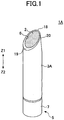
- FIGS. 1 and 2 are diagrams illustrating a stick cosmetic advancing container 1A (simply referred to as "advancing container” hereinafter) according to an embodiment of the present invention.
- FIG. 1 is an external perspective view of the advancing container 1A
- FIG. 2 is a cross-sectional view of the advancing container 1A.
- the illustrated advancing container 1A is divided by a center line A where the right side portion shows a stick type cosmetic 2 that has not yet advanced forward (before usage) and the left side portion shows the stick type cosmetic 2 that has advanced to the end (usage end) .
- the illustrated advancing container 1A is held by a user upon being used, and has the function of enabling the stick type cosmetic 2 to advance forward (i.e., to move in the direction of arrow Z1 in FIGS. 1 and 2 ).
- the stick type cosmetic 2 is made of soft material rather than material with desirable characteristics for improving usability. It is noted that the stick cosmetic advancing container 1A is not limited to being used for accommodating lipstick and may equally be used as a container for accommodating other types of stick type cosmetics such as eye shadow.
- the advancing container 1A mainly includes a sleeve 3A (outer tube), an interior plate 4, and a moving mechanism 5.
- the sleeve 3A may be formed by arranging metal or resin into a cylindrical hollow structure, and the stick type cosmetic may be accommodated within the sleeve 3A. Since the sleeve 3A is arranged into a cylindrical hollow structure, a hollow portion 23A having an oval cross-sectional shape is formed within the sleeve 3A. It is noted that the diameter of the hollow portion 23A (represented by arrow D in FIG. 2 ) is arranged to be uniform throughout the length (Z1-Z2 directions) of the sleeve 3A.
- an application opening 6 is formed at the upper tip portion of the sleeve 3A (Z1 direction tip portion in FIGS. 1 and 2 ), and the stick type cosmetic 2 is arranged to advance forward from this application opening 6. Also, the application opening 6 is arranged to form a predetermined angle with respect to the central axis (represented by the one-dotted line A in FIG. 2 ) of the sleeve 3A as is described in detail below.
- a user may hold the stick cosmetic advancing container 1A at a certain angle so that the application opening 6 (the stick type cosmetic 2 coming out of the application opening 6) may face the lips (application portion) of the user.
- the stick cosmetic advancing container 1A may be held so that the left side of the sleeve 3A in FIG. 2 (referred to as “inner side” hereinafter) is positioned toward the user, and the right side of the sleeve 3A in FIG. 2 (referred to as "outer side”) is positioned outward with respect to the user.
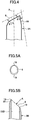
- the outer side of the sleeve 3A has an outer side inclined surface 20 that is inclined at a predetermined angle with respect to the application opening 6 (see FIG. 4 ).
- the interior plate 4 holds the stick type cosmetic 2.
- the periphery of the interior plate 4 comes into sliding contact with the inner wall of the hollow portion 23A so that the interior plate 4 may move in the direction of arrow Z1 within the sleeve 3A.
- the stick type cosmetic 2 that is held by the interior plate 4 also moves in the direction of arrow Z1 together with the interior plate 4 to thereby advance from the application opening 6.
- the interior plate 4 is moved by the moving mechanism 5. Since the sleeve 3A is arranged to have a uniform internal cross-sectional shape throughout the moving range of the stick cosmetic 2 as is described above, stress applied to the stick type cosmetic 2 may be reduced when the stick type cosmetic 2 is moved within the sleeve 3A so that the stick type cosmetic 2 may be prevented from breaking.
- the moving mechanism 5 includes a maneuvering unit 7, a rod 9, a ratchet mechanism 12, and a screw 11.
- the maneuvering unit 7 is a rotating unit arranged at the bottom tip portion (Z2 direction side tip portion) of the sleeve 3A.
- the maneuvering unit 7 has a shaft 8 integrally formed at its center that is coaxial with the central axis A.
- the shaft 8 has plural radial engaging grooves 17 formed thereon.
- the rod 9 may be a hollow tube into which the shaft 8 may be inserted. In this arrangement, the rod 9 may move in Z1 and Z2 directions with respect to the shaft 8. Also, the interior plate 4 is rotatably mounted on the upper tip portion of the rod 9, and first engaging ribs 16 are formed at the bottom edge inner wall of the rod 9. Further, a male screw portion 10 is formed around the periphery of the rod 9.
- the first engaging ribs 16 of the rod 9 engage the engaging grooves 17 of the shaft 8 so that the rod 9 may slide with respect to the shaft 8.
- the rod 9 is arranged to move in Z1 and Z2 directions with respect to the shaft 8 and rotate together with the maneuvering unit 7 via the shaft 8 when the maneuvering unit 7 is rotated.
- the ratchet mechanism 12 is arranged at the inner side of the maneuvering unit 7, and a screw 11 is arranged at the upper portion of the ratchet mechanism 12.
- the ratchet mechanism 12 is arranged into a coil spring configuration and plural ratchet pieces 15 are arranged at its tip portion (Z1 direction tip portion).
- the periphery of the screw 11 is fixed to the inner wall of the sleeve 3A, and the inner wall portion of the screw 11 is arranged into a female screw portion 13 that is screwed together with the male screw portion 10 of the rod 9. Also, plural ratchet grooves 14 are formed on the surface of the screw 11 that faces the ratchet pieces 15.
- the ratchet pieces 15 are pushed into the ratchet grooves 14 by the elastic force of the ratchet mechanism 12.
- the ratchet grooves 14 are arranged to allow the ratchet pieces 15 to rotate in only one direction (referred to as "correct rotation” hereinafter) and restrict rotation in the reverse direction.
- the bottom edge portion of the ratchet mechanism 12 engages second engaging ribs 22 that are formed at the maneuvering unit 7. In this way, the ratchet mechanism 12 may rotate together with the maneuvering unit 7 when the maneuvering unit 7 is rotated.
- the ratchet mechanism 12 may rotate together with the maneuvering unit 7 when the maneuvering unit 7 is rotated in the correct rotation direction, and the ratchet pieces 15 formed on the Z1 side tip portion of the ratchet mechanism 12 may run over the ratchet grooves 14 formed on the female screw portion 13 as a result of which the user may feel a clicking motion.
- the user may feel the maneuvering unit 7 clicking upon rotating the maneuvering unit 7.
- the shaft 8 Upon rotating the maneuvering unit 7 in the correct rotation direction, the shaft 8 also rotates together with the maneuvering unit 7, and in turn, the rod 9 also rotates in the correct rotation direction.
- the female screw portion 13 of the screw 11 that is fixed to the sleeve 3A is screwed together with the male screw portion 10 of the rod 9.
- the rod 9 rotates in the correct rotation direction, it moves in the Z1 direction with respect to the screw 11.
- the stick type cosmetic 2 held by the interior plate 4 that is mounted on the rod 9 is also moved in the Z1 direction.
- the stick type cosmetic 2 is advanced from the application opening 6 of the sleeve 3A. Since the interior plate 4 is rotatbly mounted on the rod 9 and the periphery of the interior plate 4 is in sliding contact with the inner wall of the sleeve 3A, the interior plate 4 may not rotate even when the rod 9 is rotated so that the stick type cosmetic 2 held by the interior plate 4 may also advance without rotating.
- the pitch of the ratchet grooves 14 and the ratchet pieces 15 and the pitch of the screw portions 11 and 13 are arranged so that the stick type cosmetic 2 may advance from the application opening 6 by an optimal advancing amount (represented by distance L in FIG. 2 ) through rotation of the maneuvering unit 7 by a predetermined rotation amount for achieving one clicking motion, namely, for having each of the ratchets 15 run over one ratchet groove 14.
- an optimal advancing amount represented by distance L in FIG. 2
- Such an arrangement prevents the stick type cosmetic 2 from excessively advancing out of the application opening 6 to thereby protect the stick type cosmetic 2 from breaking even when the stick type cosmetic 2 is made of soft material.
- this arrangement enables application of the stick type cosmetic 2 on the lips under desirable conditions.
- the ratchet mechanism 12 is used as the moving mechanism 5 so that the stick type cosmetic 2 may be prevented from being retracted into the sleeve 3A once it advances therefrom.
- the stick type cosmetic 3 may be prevented from receiving stress that may be applied thereto when it is retracted into the sleeve 3A so that it may be prevented from breaking.
- the moving mechanism 5 does not necessarily have to use the ratchet mechanism 12, and other types of advancing mechanisms for moving the stick type cosmetic forward by a predetermined amount may be used as well.
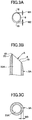
- the application opening 6 is arranged such that the outer side wall thickness W1 (see FIG. 3A ) of an outer side wall portion 18 is arranged to be less than the inner side wall thickness W2 (see FIG. 3A ) of an inner side wall portion 19 (W1 ⁇ W2). Also, a gradual change in thickness is realized from the outer side wall portion 18 to the inner side wall portion 19 so that the wall defining the application opening 6 does not include a portion with an abrupt change in shape (such as a stepped portion).
- the outer edge of the sleeve 3A and the outer edge of the stick type cosmetic 2 are disposed at substantially the same position; in other words, as is the case with a conventional stick type cosmetic, only the outer edge of the stick type cosmetic 2 comes into contact with a lip of the user upon applying the stick type cosmetic 2.
- the wall thickness of the application opening 6 of the sleeve 3A as opposed to realizing a uniform wall thickness; namely, by arranging the thickness W1 of the outer side wall portion 18 to be less than the thickness W2 of the inner side wall portion 19, the outlines of a desired application portion may be accurately drawn, for example.
- the sleeve 3A itself is configured to enable accurate outline depiction of a desired application portion, only a slight amount of the stick type cosmetic 2 may need to be advanced upon applying the stick type cosmetic 2. In other words, the stick type cosmetic 2 does not have to be advanced from the sleeve 3A at great length so that the stick type cosmetic 2 may be prevented from breaking.
- the outer side wall width W1 of the outer side wall portion 18 is arranged to be within a range of 0.2-0.8 mm (0.2 mm ⁇ W1 ⁇ 0.8 mm). It is noted that when the outer side wall thickness W1 is less than 0.2 mm, it may be difficult to form the application opening 6 at the sleeve 3A, and if the outer side wall width W1 is greater than 0.8 mm, it may be difficult to accurately draw the outlines of the desired application portion upon applying the stick type cosmetic 2.
- a so-called chamfering process is performed on the outer side wall portion 18, and the curvature radius of the resulting chamfer is within a range of 0.3-3 mm.
- the surface of the application opening 6 (opening surface) is arranged to incline at a predetermined angle (represented by ⁇ 1 in FIG. 4 ) with respect to the central axis A of the sleeve 3A and is also arranged to incline at a predetermined angle (represented by ⁇ 2 in FIG. 4 ) with respect to the outer side inclined surface 20.
- the inclination angle ⁇ 1 of the opening surface with respect to the central axis A of the sleeve 3A is within a range of 45-85 degrees (45° ⁇ ⁇ 1 ⁇ 85°).
- the stick cosmetic advancing container 1A may have to be held upright upon applying the stick type cosmetic 2 so that usability of the advancing container 1A may be degraded.
- the stick cosmetic container 1A may have to be held at a substantially horizontal position which also creates inconveniences with regard to usability.
- the inclination angle ⁇ 2 of the opening surface with respect to the outer side inclined surface 20 of the sleeve 3A is within a range of 45-65 degrees (45° ⁇ ⁇ 1 ⁇ 65°), for example.
- the angle ⁇ 2 formed by the outer side inclined surface 20 and the surface of the application opening 6 may be within a predetermined angle range as is described above, usability of the stick cosmetic advancing container 1A may be improved.
- the inclination angle ⁇ 2 when the inclination angle ⁇ 2 is greater than 65 degrees, a user may have trouble viewing the application position of the tip (outer side wall portion 18) of the stick cosmetic container 1A upon applying the stick type cosmetic 2 using a mirror and may have difficulties in accurately drawing outlines of the application portion. Also, in the case of using a mirror, images of the advancing container 1A as well as the hand of the user may be reflected on the mirror and this may also create inconveniences in applying the stick type cosmetic 2. On the other hand, when the inclination angle ⁇ 2 formed by the outer side inclined surface 20 and the opening surface is less than 45 degrees, the advancing container 1A may be too narrow for practical use. Accordingly, by setting the inclination angle ⁇ 2 of the surface of the application opening 6 within a predetermined angle range as is described above, the stick type cosmetic 2 may be suitably applied using the advancing container 1A.
- the sleeve 3B has an oval cross-sectional shape.
- the interior plate 4 of the moving mechanism is a non-rotating member.
- FIGS. 6A and 6B show advancing containers 1B and 1C as second and third modified embodiments of the advancing container 1A. It is noted that in these drawings, components that are identical to those described in relation to FIGS. 1-4 are given the same reference numerals and their descriptions are omitted.
- the advancing container 1A described above with reference to FIGS. 1-4 is made of metal or resin that is shaped into a cylindrical hollow structure and the sleeve 3A is also made of the same material.
- the advancing containers 1B and 1C of the second and third modified embodiments are characterized in that their respective sleeves 3C and 3D are made of plural types of materials.
- the advancing container 1B of the second modified embodiment shown in FIG. 6A includes a metal inner tube 25 that is covered by a silicon rubber outer tube 26 as the sleeve 3C. It is noted that in this embodiment, the metal inner tube 25 is completely covered by the silicon rubber outer tube 26 so that the application opening 6 (i.e., portion that comes into contact with the lips of the user) is also covered by the silicon rubber opening 26. Such an arrangement may provide more comfort to the user in when the application opening 6 comes into with the lips of the user, for example.
- the present embodiment may also have the advantages of catering to users having allergies to metal, for example.
- the advancing container 1C of the third modified embodiment as is shown in FIG. 6B has a metal inner tube 25 that is covered by a resin outer tube 27 as the sleeve 3D.
- both the metal inner tube 25 and the resin outer tube 27 are exposed at the surface of the application opening 6.
Landscapes
- Containers And Packaging Bodies Having A Special Means To Remove Contents (AREA)
Applications Claiming Priority (2)
| Application Number | Priority Date | Filing Date | Title |
|---|---|---|---|
| JP2004357020A JP4134015B2 (ja) | 2004-12-09 | 2004-12-09 | 棒状化粧料繰り出し容器 |
| PCT/JP2005/022665 WO2006062192A1 (ja) | 2004-12-09 | 2005-12-09 | 棒状化粧料繰り出し容器 |
Publications (3)
| Publication Number | Publication Date |
|---|---|
| EP1820418A1 EP1820418A1 (en) | 2007-08-22 |
| EP1820418A4 EP1820418A4 (en) | 2010-12-08 |
| EP1820418B1 true EP1820418B1 (en) | 2019-09-25 |
Family
ID=36578012
Family Applications (1)
| Application Number | Title | Priority Date | Filing Date |
|---|---|---|---|
| EP05814508.7A Expired - Lifetime EP1820418B1 (en) | 2004-12-09 | 2005-12-09 | Stick cosmetic advancing container |
Country Status (8)
| Country | Link |
|---|---|
| US (1) | US7891896B2 (enExample) |
| EP (1) | EP1820418B1 (enExample) |
| JP (1) | JP4134015B2 (enExample) |
| KR (1) | KR101234708B1 (enExample) |
| CN (1) | CN100579414C (enExample) |
| ES (1) | ES2761869T3 (enExample) |
| TW (1) | TW200631521A (enExample) |
| WO (1) | WO2006062192A1 (enExample) |
Families Citing this family (14)
| Publication number | Priority date | Publication date | Assignee | Title |
|---|---|---|---|---|
| JP3779679B2 (ja) | 2002-12-25 | 2006-05-31 | 花王株式会社 | 毛髪洗浄剤 |
| JP5080115B2 (ja) * | 2007-03-23 | 2012-11-21 | 株式会社コーセー | スティック状化粧料用容器 |
| JP4499811B2 (ja) | 2008-05-28 | 2010-07-07 | 株式会社トキワ | 塗布材押出容器 |
| US8328448B1 (en) * | 2010-06-09 | 2012-12-11 | Hufnagel Randall S | Hardware hole filling device |
| JP5108919B2 (ja) * | 2010-06-28 | 2012-12-26 | 株式会社トキワ | 充填物押出容器 |
| USD739077S1 (en) * | 2013-04-19 | 2015-09-15 | Elc Management Llc | Lipstick bullet |
| USD741004S1 (en) | 2013-04-19 | 2015-10-13 | Elc Management Llc | Lipstick bullet |
| MX391509B (es) * | 2014-09-22 | 2025-03-21 | Cosmetic Group Usa Inc | Lapices, barras y comprimidos de polvo horneado y metodos para elaborar y utilizar los mismos. |
| JP6587339B2 (ja) * | 2015-06-17 | 2019-10-09 | 株式会社タイキ | 簡易棒状化粧品用の用具と簡易棒状化粧品 |
| JP2017189466A (ja) * | 2016-04-14 | 2017-10-19 | 株式会社トキワ | 棒状化粧料繰出容器 |
| USD822330S1 (en) * | 2016-08-15 | 2018-07-10 | Farm 23 Sl | Confectionary |
| FR3071389B1 (fr) * | 2017-09-28 | 2022-06-24 | Reboul S A S | Mecanisme tournant d'un etui cosmetique |
| US11382400B2 (en) | 2018-08-10 | 2022-07-12 | Go Products Co. | Material applicator |
| TW202029906A (zh) * | 2019-01-23 | 2020-08-16 | 日商資生堂股份有限公司 | 送出容器 |
Citations (1)
| Publication number | Priority date | Publication date | Assignee | Title |
|---|---|---|---|---|
| US2457342A (en) * | 1946-09-24 | 1948-12-28 | Chester H Braselton | Lipstick |
Family Cites Families (14)
| Publication number | Priority date | Publication date | Assignee | Title |
|---|---|---|---|---|
| FR728208A (fr) * | 1931-12-14 | 1932-07-02 | Distributeur pour fards, crèmes, cosmétiques et tous autres produits similaires | |
| US3219044A (en) * | 1962-05-02 | 1965-11-23 | Bau Robert Gordon | Cosmetic make-up device |
| DE3728427C1 (de) * | 1987-08-26 | 1988-12-01 | Schwan Stabilo Schwanhaeusser | Auftragsgeraet mit einer Mine aus einer streichfaehigen Masse |
| WO1989007078A1 (fr) * | 1988-01-30 | 1989-08-10 | Pentel Kabushiki Kaisha | Organe d'extrusion |
| JP2513373Y2 (ja) * | 1988-01-30 | 1996-10-02 | ぺんてる株式会社 | 押出具 |
| DE3835679A1 (de) * | 1988-10-20 | 1990-04-26 | Faber Castell A W | Fuellminenstift, insbesondere kosmetikstift |
| JPH02142674A (ja) | 1988-11-22 | 1990-05-31 | Showa Alum Corp | 管状物の接続方法 |
| JP2678572B2 (ja) * | 1994-07-18 | 1997-11-17 | 株式会社ヒダン | 棒状化粧料容器 |
| US5813421A (en) * | 1997-07-09 | 1998-09-29 | Der Kwei Cosmetic Packaging Co., Limited | Lipstick swivel mechanism |
| CN2356552Y (zh) * | 1998-12-24 | 2000-01-05 | 郭镇辉 | 具有定位结构的唇膏盒 |
| ID29118A (id) * | 2000-02-02 | 2001-08-02 | Chiem Cosmetic Packaging Co Lt | Wadah cat pemerah bibir |
| JP4711277B2 (ja) * | 2001-05-31 | 2011-06-29 | 株式会社吉野工業所 | 棒状の充填部材の繰り出し容器 |
| ATE467364T1 (de) * | 2001-09-28 | 2010-05-15 | Kose Corp | Behälter für stiftartige kosmetika |
| JP2004201907A (ja) | 2002-12-25 | 2004-07-22 | Kao Corp | 固形塗布材の繰り出し容器 |
-
2004
- 2004-12-09 JP JP2004357020A patent/JP4134015B2/ja not_active Expired - Lifetime
-
2005
- 2005-12-09 EP EP05814508.7A patent/EP1820418B1/en not_active Expired - Lifetime
- 2005-12-09 ES ES05814508T patent/ES2761869T3/es not_active Expired - Lifetime
- 2005-12-09 WO PCT/JP2005/022665 patent/WO2006062192A1/ja not_active Ceased
- 2005-12-09 CN CN200580041994A patent/CN100579414C/zh not_active Expired - Lifetime
- 2005-12-09 KR KR1020077012969A patent/KR101234708B1/ko not_active Expired - Fee Related
- 2005-12-09 US US11/667,832 patent/US7891896B2/en active Active
- 2005-12-09 TW TW094143769A patent/TW200631521A/zh not_active IP Right Cessation
Patent Citations (1)
| Publication number | Priority date | Publication date | Assignee | Title |
|---|---|---|---|---|
| US2457342A (en) * | 1946-09-24 | 1948-12-28 | Chester H Braselton | Lipstick |
Also Published As
| Publication number | Publication date |
|---|---|
| TW200631521A (en) | 2006-09-16 |
| JP4134015B2 (ja) | 2008-08-13 |
| US7891896B2 (en) | 2011-02-22 |
| EP1820418A1 (en) | 2007-08-22 |
| KR101234708B1 (ko) | 2013-02-19 |
| ES2761869T3 (es) | 2020-05-21 |
| CN101072523A (zh) | 2007-11-14 |
| KR20070087599A (ko) | 2007-08-28 |
| WO2006062192A1 (ja) | 2006-06-15 |
| EP1820418A4 (en) | 2010-12-08 |
| CN100579414C (zh) | 2010-01-13 |
| US20080050169A1 (en) | 2008-02-28 |
| TWI370727B (enExample) | 2012-08-21 |
| JP2006158777A (ja) | 2006-06-22 |
Similar Documents
| Publication | Publication Date | Title |
|---|---|---|
| US7891896B2 (en) | Stick cosmetic advancing container | |
| US8936408B2 (en) | Liquid material feeding container | |
| US10506864B2 (en) | Stick-shaped cosmetic material dispensing container | |
| US6244769B1 (en) | Stick cosmetic container | |
| JP3959277B2 (ja) | 棒状物繰り出し具 | |
| EP3864999A1 (en) | Mechanism for cosmetic container and container comprising said mechanism | |
| CN110063563A (zh) | 涂布容器 | |
| CN114947343B (zh) | 涂布材料旋出容器 | |
| KR100578785B1 (ko) | 막대형 화장재료 조출 용기 | |
| JP2003159119A (ja) | 棒状化粧材繰出容器 | |
| JP2001218621A (ja) | 棒状化粧材繰出容器 | |
| JP2000135116A (ja) | 化粧材容器および化粧材容器のカートリッジ | |
| TWI298996B (en) | Applicator devices with a short twist-off protective cap | |
| JPH0538679Y2 (enExample) | ||
| JP2012029784A (ja) | 棒状化粧料繰出し容器 | |
| KR20200017225A (ko) | 화장품 용기 | |
| JP2025056620A (ja) | 描画材容器カートリッジおよび描画材容器セット | |
| JP2023183800A (ja) | 棒状部材の繰出容器 | |
| JP2002300917A (ja) | カートリッジ式化粧材容器 | |
| JP2023179134A (ja) | 装着具 | |
| JP2023175372A (ja) | 塗布具付きキャップ及び塗布容器 | |
| JP2023062636A (ja) | 塗布体付き化粧料容器 | |
| JPH08332114A (ja) | 棒状化粧料繰出容器 | |
| JPH10184U (ja) | 棒状物繰り出し容器付き筆記具 | |
| JP2004089529A (ja) | 棒状化粧料繰出容器 |
Legal Events
| Date | Code | Title | Description |
|---|---|---|---|
| PUAI | Public reference made under article 153(3) epc to a published international application that has entered the european phase |
Free format text: ORIGINAL CODE: 0009012 |
|
| 17P | Request for examination filed |
Effective date: 20070524 |
|
| AK | Designated contracting states |
Kind code of ref document: A1 Designated state(s): DE ES FR GB IT |
|
| RBV | Designated contracting states (corrected) |
Designated state(s): DE ES FR GB IT |
|
| DAX | Request for extension of the european patent (deleted) | ||
| A4 | Supplementary search report drawn up and despatched |
Effective date: 20101105 |
|
| 17Q | First examination report despatched |
Effective date: 20140423 |
|
| RIN1 | Information on inventor provided before grant (corrected) |
Inventor name: NASU, MIEKO |
|
| GRAP | Despatch of communication of intention to grant a patent |
Free format text: ORIGINAL CODE: EPIDOSNIGR1 |
|
| RAP1 | Party data changed (applicant data changed or rights of an application transferred) |
Owner name: SHISEIDO COMPANY, LTD. |
|
| INTG | Intention to grant announced |
Effective date: 20190418 |
|
| GRAS | Grant fee paid |
Free format text: ORIGINAL CODE: EPIDOSNIGR3 |
|
| GRAA | (expected) grant |
Free format text: ORIGINAL CODE: 0009210 |
|
| AK | Designated contracting states |
Kind code of ref document: B1 Designated state(s): DE ES FR GB IT |
|
| REG | Reference to a national code |
Ref country code: GB Ref legal event code: FG4D |
|
| REG | Reference to a national code |
Ref country code: DE Ref legal event code: R096 Ref document number: 602005056283 Country of ref document: DE |
|
| PGFP | Annual fee paid to national office [announced via postgrant information from national office to epo] |
Ref country code: DE Payment date: 20191227 Year of fee payment: 15 Ref country code: ES Payment date: 20200122 Year of fee payment: 15 Ref country code: GB Payment date: 20191220 Year of fee payment: 15 Ref country code: IT Payment date: 20200113 Year of fee payment: 15 |
|
| REG | Reference to a national code |
Ref country code: ES Ref legal event code: FG2A Ref document number: 2761869 Country of ref document: ES Kind code of ref document: T3 Effective date: 20200521 |
|
| REG | Reference to a national code |
Ref country code: DE Ref legal event code: R097 Ref document number: 602005056283 Country of ref document: DE |
|
| PLBE | No opposition filed within time limit |
Free format text: ORIGINAL CODE: 0009261 |
|
| STAA | Information on the status of an ep patent application or granted ep patent |
Free format text: STATUS: NO OPPOSITION FILED WITHIN TIME LIMIT |
|
| 26N | No opposition filed |
Effective date: 20200626 |
|
| REG | Reference to a national code |
Ref country code: DE Ref legal event code: R119 Ref document number: 602005056283 Country of ref document: DE |
|
| GBPC | Gb: european patent ceased through non-payment of renewal fee |
Effective date: 20201209 |
|
| PG25 | Lapsed in a contracting state [announced via postgrant information from national office to epo] |
Ref country code: IT Free format text: LAPSE BECAUSE OF NON-PAYMENT OF DUE FEES Effective date: 20201209 |
|
| PG25 | Lapsed in a contracting state [announced via postgrant information from national office to epo] |
Ref country code: GB Free format text: LAPSE BECAUSE OF NON-PAYMENT OF DUE FEES Effective date: 20201209 Ref country code: DE Free format text: LAPSE BECAUSE OF NON-PAYMENT OF DUE FEES Effective date: 20210701 |
|
| REG | Reference to a national code |
Ref country code: ES Ref legal event code: FD2A Effective date: 20220208 |
|
| PG25 | Lapsed in a contracting state [announced via postgrant information from national office to epo] |
Ref country code: ES Free format text: LAPSE BECAUSE OF NON-PAYMENT OF DUE FEES Effective date: 20201210 |
|
| P01 | Opt-out of the competence of the unified patent court (upc) registered |
Effective date: 20230519 |
|
| PGFP | Annual fee paid to national office [announced via postgrant information from national office to epo] |
Ref country code: FR Payment date: 20241121 Year of fee payment: 20 |