EP1800929A2 - Doppelkupplungsanordnung - Google Patents
Doppelkupplungsanordnung Download PDFInfo
- Publication number
- EP1800929A2 EP1800929A2 EP06024765A EP06024765A EP1800929A2 EP 1800929 A2 EP1800929 A2 EP 1800929A2 EP 06024765 A EP06024765 A EP 06024765A EP 06024765 A EP06024765 A EP 06024765A EP 1800929 A2 EP1800929 A2 EP 1800929A2
- Authority
- EP
- European Patent Office
- Prior art keywords
- clutch
- friction
- dual
- friction clutch
- arrangement according
- Prior art date
- Legal status (The legal status is an assumption and is not a legal conclusion. Google has not performed a legal analysis and makes no representation as to the accuracy of the status listed.)
- Granted
Links
Images

Classifications
-
- B—PERFORMING OPERATIONS; TRANSPORTING
- B60—VEHICLES IN GENERAL
- B60K—ARRANGEMENT OR MOUNTING OF PROPULSION UNITS OR OF TRANSMISSIONS IN VEHICLES; ARRANGEMENT OR MOUNTING OF PLURAL DIVERSE PRIME-MOVERS IN VEHICLES; AUXILIARY DRIVES FOR VEHICLES; INSTRUMENTATION OR DASHBOARDS FOR VEHICLES; ARRANGEMENTS IN CONNECTION WITH COOLING, AIR INTAKE, GAS EXHAUST OR FUEL SUPPLY OF PROPULSION UNITS IN VEHICLES
- B60K6/00—Arrangement or mounting of plural diverse prime-movers for mutual or common propulsion, e.g. hybrid propulsion systems comprising electric motors and internal combustion engines ; Control systems therefor, i.e. systems controlling two or more prime movers, or controlling one of these prime movers and any of the transmission, drive or drive units Informative references: mechanical gearings with secondary electric drive F16H3/72; arrangements for handling mechanical energy structurally associated with the dynamo-electric machine H02K7/00; machines comprising structurally interrelated motor and generator parts H02K51/00; dynamo-electric machines not otherwise provided for in H02K see H02K99/00
- B60K6/20—Arrangement or mounting of plural diverse prime-movers for mutual or common propulsion, e.g. hybrid propulsion systems comprising electric motors and internal combustion engines ; Control systems therefor, i.e. systems controlling two or more prime movers, or controlling one of these prime movers and any of the transmission, drive or drive units Informative references: mechanical gearings with secondary electric drive F16H3/72; arrangements for handling mechanical energy structurally associated with the dynamo-electric machine H02K7/00; machines comprising structurally interrelated motor and generator parts H02K51/00; dynamo-electric machines not otherwise provided for in H02K see H02K99/00 the prime-movers consisting of electric motors and internal combustion engines, e.g. HEVs
- B60K6/42—Arrangement or mounting of plural diverse prime-movers for mutual or common propulsion, e.g. hybrid propulsion systems comprising electric motors and internal combustion engines ; Control systems therefor, i.e. systems controlling two or more prime movers, or controlling one of these prime movers and any of the transmission, drive or drive units Informative references: mechanical gearings with secondary electric drive F16H3/72; arrangements for handling mechanical energy structurally associated with the dynamo-electric machine H02K7/00; machines comprising structurally interrelated motor and generator parts H02K51/00; dynamo-electric machines not otherwise provided for in H02K see H02K99/00 the prime-movers consisting of electric motors and internal combustion engines, e.g. HEVs characterised by the architecture of the hybrid electric vehicle
- B60K6/48—Parallel type
-
- B—PERFORMING OPERATIONS; TRANSPORTING
- B60—VEHICLES IN GENERAL
- B60K—ARRANGEMENT OR MOUNTING OF PROPULSION UNITS OR OF TRANSMISSIONS IN VEHICLES; ARRANGEMENT OR MOUNTING OF PLURAL DIVERSE PRIME-MOVERS IN VEHICLES; AUXILIARY DRIVES FOR VEHICLES; INSTRUMENTATION OR DASHBOARDS FOR VEHICLES; ARRANGEMENTS IN CONNECTION WITH COOLING, AIR INTAKE, GAS EXHAUST OR FUEL SUPPLY OF PROPULSION UNITS IN VEHICLES
- B60K6/00—Arrangement or mounting of plural diverse prime-movers for mutual or common propulsion, e.g. hybrid propulsion systems comprising electric motors and internal combustion engines ; Control systems therefor, i.e. systems controlling two or more prime movers, or controlling one of these prime movers and any of the transmission, drive or drive units Informative references: mechanical gearings with secondary electric drive F16H3/72; arrangements for handling mechanical energy structurally associated with the dynamo-electric machine H02K7/00; machines comprising structurally interrelated motor and generator parts H02K51/00; dynamo-electric machines not otherwise provided for in H02K see H02K99/00
- B60K6/20—Arrangement or mounting of plural diverse prime-movers for mutual or common propulsion, e.g. hybrid propulsion systems comprising electric motors and internal combustion engines ; Control systems therefor, i.e. systems controlling two or more prime movers, or controlling one of these prime movers and any of the transmission, drive or drive units Informative references: mechanical gearings with secondary electric drive F16H3/72; arrangements for handling mechanical energy structurally associated with the dynamo-electric machine H02K7/00; machines comprising structurally interrelated motor and generator parts H02K51/00; dynamo-electric machines not otherwise provided for in H02K see H02K99/00 the prime-movers consisting of electric motors and internal combustion engines, e.g. HEVs
- B60K6/22—Arrangement or mounting of plural diverse prime-movers for mutual or common propulsion, e.g. hybrid propulsion systems comprising electric motors and internal combustion engines ; Control systems therefor, i.e. systems controlling two or more prime movers, or controlling one of these prime movers and any of the transmission, drive or drive units Informative references: mechanical gearings with secondary electric drive F16H3/72; arrangements for handling mechanical energy structurally associated with the dynamo-electric machine H02K7/00; machines comprising structurally interrelated motor and generator parts H02K51/00; dynamo-electric machines not otherwise provided for in H02K see H02K99/00 the prime-movers consisting of electric motors and internal combustion engines, e.g. HEVs characterised by apparatus, components or means specially adapted for HEVs
- B60K6/38—Arrangement or mounting of plural diverse prime-movers for mutual or common propulsion, e.g. hybrid propulsion systems comprising electric motors and internal combustion engines ; Control systems therefor, i.e. systems controlling two or more prime movers, or controlling one of these prime movers and any of the transmission, drive or drive units Informative references: mechanical gearings with secondary electric drive F16H3/72; arrangements for handling mechanical energy structurally associated with the dynamo-electric machine H02K7/00; machines comprising structurally interrelated motor and generator parts H02K51/00; dynamo-electric machines not otherwise provided for in H02K see H02K99/00 the prime-movers consisting of electric motors and internal combustion engines, e.g. HEVs characterised by apparatus, components or means specially adapted for HEVs characterised by the driveline clutches
- B60K6/387—Actuated clutches, i.e. clutches engaged or disengaged by electric, hydraulic or mechanical actuating means
-
- B—PERFORMING OPERATIONS; TRANSPORTING
- B60—VEHICLES IN GENERAL
- B60K—ARRANGEMENT OR MOUNTING OF PROPULSION UNITS OR OF TRANSMISSIONS IN VEHICLES; ARRANGEMENT OR MOUNTING OF PLURAL DIVERSE PRIME-MOVERS IN VEHICLES; AUXILIARY DRIVES FOR VEHICLES; INSTRUMENTATION OR DASHBOARDS FOR VEHICLES; ARRANGEMENTS IN CONNECTION WITH COOLING, AIR INTAKE, GAS EXHAUST OR FUEL SUPPLY OF PROPULSION UNITS IN VEHICLES
- B60K6/00—Arrangement or mounting of plural diverse prime-movers for mutual or common propulsion, e.g. hybrid propulsion systems comprising electric motors and internal combustion engines ; Control systems therefor, i.e. systems controlling two or more prime movers, or controlling one of these prime movers and any of the transmission, drive or drive units Informative references: mechanical gearings with secondary electric drive F16H3/72; arrangements for handling mechanical energy structurally associated with the dynamo-electric machine H02K7/00; machines comprising structurally interrelated motor and generator parts H02K51/00; dynamo-electric machines not otherwise provided for in H02K see H02K99/00
- B60K6/20—Arrangement or mounting of plural diverse prime-movers for mutual or common propulsion, e.g. hybrid propulsion systems comprising electric motors and internal combustion engines ; Control systems therefor, i.e. systems controlling two or more prime movers, or controlling one of these prime movers and any of the transmission, drive or drive units Informative references: mechanical gearings with secondary electric drive F16H3/72; arrangements for handling mechanical energy structurally associated with the dynamo-electric machine H02K7/00; machines comprising structurally interrelated motor and generator parts H02K51/00; dynamo-electric machines not otherwise provided for in H02K see H02K99/00 the prime-movers consisting of electric motors and internal combustion engines, e.g. HEVs
- B60K6/22—Arrangement or mounting of plural diverse prime-movers for mutual or common propulsion, e.g. hybrid propulsion systems comprising electric motors and internal combustion engines ; Control systems therefor, i.e. systems controlling two or more prime movers, or controlling one of these prime movers and any of the transmission, drive or drive units Informative references: mechanical gearings with secondary electric drive F16H3/72; arrangements for handling mechanical energy structurally associated with the dynamo-electric machine H02K7/00; machines comprising structurally interrelated motor and generator parts H02K51/00; dynamo-electric machines not otherwise provided for in H02K see H02K99/00 the prime-movers consisting of electric motors and internal combustion engines, e.g. HEVs characterised by apparatus, components or means specially adapted for HEVs
- B60K6/40—Arrangement or mounting of plural diverse prime-movers for mutual or common propulsion, e.g. hybrid propulsion systems comprising electric motors and internal combustion engines ; Control systems therefor, i.e. systems controlling two or more prime movers, or controlling one of these prime movers and any of the transmission, drive or drive units Informative references: mechanical gearings with secondary electric drive F16H3/72; arrangements for handling mechanical energy structurally associated with the dynamo-electric machine H02K7/00; machines comprising structurally interrelated motor and generator parts H02K51/00; dynamo-electric machines not otherwise provided for in H02K see H02K99/00 the prime-movers consisting of electric motors and internal combustion engines, e.g. HEVs characterised by apparatus, components or means specially adapted for HEVs characterised by the assembly or relative disposition of components
-
- B—PERFORMING OPERATIONS; TRANSPORTING
- B60—VEHICLES IN GENERAL
- B60K—ARRANGEMENT OR MOUNTING OF PROPULSION UNITS OR OF TRANSMISSIONS IN VEHICLES; ARRANGEMENT OR MOUNTING OF PLURAL DIVERSE PRIME-MOVERS IN VEHICLES; AUXILIARY DRIVES FOR VEHICLES; INSTRUMENTATION OR DASHBOARDS FOR VEHICLES; ARRANGEMENTS IN CONNECTION WITH COOLING, AIR INTAKE, GAS EXHAUST OR FUEL SUPPLY OF PROPULSION UNITS IN VEHICLES
- B60K6/00—Arrangement or mounting of plural diverse prime-movers for mutual or common propulsion, e.g. hybrid propulsion systems comprising electric motors and internal combustion engines ; Control systems therefor, i.e. systems controlling two or more prime movers, or controlling one of these prime movers and any of the transmission, drive or drive units Informative references: mechanical gearings with secondary electric drive F16H3/72; arrangements for handling mechanical energy structurally associated with the dynamo-electric machine H02K7/00; machines comprising structurally interrelated motor and generator parts H02K51/00; dynamo-electric machines not otherwise provided for in H02K see H02K99/00
- B60K6/20—Arrangement or mounting of plural diverse prime-movers for mutual or common propulsion, e.g. hybrid propulsion systems comprising electric motors and internal combustion engines ; Control systems therefor, i.e. systems controlling two or more prime movers, or controlling one of these prime movers and any of the transmission, drive or drive units Informative references: mechanical gearings with secondary electric drive F16H3/72; arrangements for handling mechanical energy structurally associated with the dynamo-electric machine H02K7/00; machines comprising structurally interrelated motor and generator parts H02K51/00; dynamo-electric machines not otherwise provided for in H02K see H02K99/00 the prime-movers consisting of electric motors and internal combustion engines, e.g. HEVs
- B60K6/50—Architecture of the driveline characterised by arrangement or kind of transmission units
- B60K6/54—Transmission for changing ratio
- B60K6/547—Transmission for changing ratio the transmission being a stepped gearing
-
- F—MECHANICAL ENGINEERING; LIGHTING; HEATING; WEAPONS; BLASTING
- F16—ENGINEERING ELEMENTS AND UNITS; GENERAL MEASURES FOR PRODUCING AND MAINTAINING EFFECTIVE FUNCTIONING OF MACHINES OR INSTALLATIONS; THERMAL INSULATION IN GENERAL
- F16D—COUPLINGS FOR TRANSMITTING ROTATION; CLUTCHES; BRAKES
- F16D25/00—Fluid-actuated clutches
- F16D25/06—Fluid-actuated clutches in which the fluid actuates a piston incorporated in, i.e. rotating with the clutch
- F16D25/062—Fluid-actuated clutches in which the fluid actuates a piston incorporated in, i.e. rotating with the clutch the clutch having friction surfaces
- F16D25/063—Fluid-actuated clutches in which the fluid actuates a piston incorporated in, i.e. rotating with the clutch the clutch having friction surfaces with clutch members exclusively moving axially
- F16D25/0635—Fluid-actuated clutches in which the fluid actuates a piston incorporated in, i.e. rotating with the clutch the clutch having friction surfaces with clutch members exclusively moving axially with flat friction surfaces, e.g. discs
- F16D25/0638—Fluid-actuated clutches in which the fluid actuates a piston incorporated in, i.e. rotating with the clutch the clutch having friction surfaces with clutch members exclusively moving axially with flat friction surfaces, e.g. discs with more than two discs, e.g. multiple lamellae
-
- F—MECHANICAL ENGINEERING; LIGHTING; HEATING; WEAPONS; BLASTING
- F16—ENGINEERING ELEMENTS AND UNITS; GENERAL MEASURES FOR PRODUCING AND MAINTAINING EFFECTIVE FUNCTIONING OF MACHINES OR INSTALLATIONS; THERMAL INSULATION IN GENERAL
- F16D—COUPLINGS FOR TRANSMITTING ROTATION; CLUTCHES; BRAKES
- F16D25/00—Fluid-actuated clutches
- F16D25/10—Clutch systems with a plurality of fluid-actuated clutches
-
- F—MECHANICAL ENGINEERING; LIGHTING; HEATING; WEAPONS; BLASTING
- F16—ENGINEERING ELEMENTS AND UNITS; GENERAL MEASURES FOR PRODUCING AND MAINTAINING EFFECTIVE FUNCTIONING OF MACHINES OR INSTALLATIONS; THERMAL INSULATION IN GENERAL
- F16H—GEARING
- F16H3/00—Toothed gearings for conveying rotary motion with variable gear ratio or for reversing rotary motion
- F16H3/006—Toothed gearings for conveying rotary motion with variable gear ratio or for reversing rotary motion power being selectively transmitted by either one of the parallel flow paths
-
- B—PERFORMING OPERATIONS; TRANSPORTING
- B60—VEHICLES IN GENERAL
- B60Y—INDEXING SCHEME RELATING TO ASPECTS CROSS-CUTTING VEHICLE TECHNOLOGY
- B60Y2400/00—Special features of vehicle units
- B60Y2400/42—Clutches or brakes
- B60Y2400/428—Double clutch arrangements; Dual clutches
-
- F—MECHANICAL ENGINEERING; LIGHTING; HEATING; WEAPONS; BLASTING
- F16—ENGINEERING ELEMENTS AND UNITS; GENERAL MEASURES FOR PRODUCING AND MAINTAINING EFFECTIVE FUNCTIONING OF MACHINES OR INSTALLATIONS; THERMAL INSULATION IN GENERAL
- F16D—COUPLINGS FOR TRANSMITTING ROTATION; CLUTCHES; BRAKES
- F16D21/00—Systems comprising a plurality of actuated clutches
- F16D21/02—Systems comprising a plurality of actuated clutches for interconnecting three or more shafts or other transmission members in different ways
- F16D21/06—Systems comprising a plurality of actuated clutches for interconnecting three or more shafts or other transmission members in different ways at least two driving shafts or two driven shafts being concentric
- F16D2021/0661—Hydraulically actuated multiple lamellae clutches
-
- F—MECHANICAL ENGINEERING; LIGHTING; HEATING; WEAPONS; BLASTING
- F16—ENGINEERING ELEMENTS AND UNITS; GENERAL MEASURES FOR PRODUCING AND MAINTAINING EFFECTIVE FUNCTIONING OF MACHINES OR INSTALLATIONS; THERMAL INSULATION IN GENERAL
- F16H—GEARING
- F16H57/00—General details of gearing
- F16H57/04—Features relating to lubrication or cooling or heating
- F16H57/0467—Elements of gearings to be lubricated, cooled or heated
- F16H57/0476—Electric machines and gearing, i.e. joint lubrication or cooling or heating thereof
-
- Y—GENERAL TAGGING OF NEW TECHNOLOGICAL DEVELOPMENTS; GENERAL TAGGING OF CROSS-SECTIONAL TECHNOLOGIES SPANNING OVER SEVERAL SECTIONS OF THE IPC; TECHNICAL SUBJECTS COVERED BY FORMER USPC CROSS-REFERENCE ART COLLECTIONS [XRACs] AND DIGESTS
- Y02—TECHNOLOGIES OR APPLICATIONS FOR MITIGATION OR ADAPTATION AGAINST CLIMATE CHANGE
- Y02T—CLIMATE CHANGE MITIGATION TECHNOLOGIES RELATED TO TRANSPORTATION
- Y02T10/00—Road transport of goods or passengers
- Y02T10/60—Other road transportation technologies with climate change mitigation effect
- Y02T10/62—Hybrid vehicles
Definitions
- the present invention relates to a dual-clutch arrangement with an input shaft, having a first friction clutch whose input member is connected to the input shaft and whose output member is connected to a first output shaft, with a second friction clutch whose input member is connected to the input shaft and whose output member is connected to a second output shaft. wherein the output shafts are connectable to respective input shafts of a dual-clutch transmission, and to an electric machine connected to the first output shaft.
- Dual clutch arrangements for dual clutch transmissions are well known.
- the gear stages are distributed to two parallel partial transmissions, in such a way that one sub-transmission, the odd gear ratios and the other sub-transmission are associated with the straight gear ratios.
- Each sub-transmission is also assigned on the input side its own friction clutch.
- the two friction clutches form a dual clutch assembly disposed between a drive motor (usually an internal combustion engine) and the dual clutch transmission.
- an electric machine is also connected to the dual-clutch transmission. More precisely, the electric machine is connected to the first output shaft via a wheel set. The electric machine is mounted parallel to the coaxial arrangement of the friction clutches.
- a clutch assembly which is usable for a hybrid powertrain.
- the transmission of the drive train is a conventional transmission with a plurality of gear stages, which is usually associated with a single starting and separating clutch, which is arranged between the drive motor and transmission.
- two friction clutches are not connected in parallel but serially connected, via an electric machine.
- the output member of a friction clutch is connected to the electric machine.
- the electric machine is connected to the input member of the other friction clutch.
- first friction clutch can be assigned to both the partial gear with the odd gear ratios and the part gear with the even gears.
- the distinction between the first and second friction clutch takes place here only for better illustration of the invention.
- the dual clutch arrangement can be realized with few components.
- the rotor is fixed radially outward on the output member of the first friction clutch.
- a modular dual clutch arrangement can be realized particularly easily, since the electric machine can be arranged radially outside of the friction clutches.
- the first friction clutch is a multi-plate clutch and if the output member of the first friction clutch is an outer disk carrier.
- the first and the second friction clutch are arranged axially next to each other.
- the first friction clutch is arranged on the output side.
- the first friction clutch on the input side.
- input side and output side should be understood in the present case that a friction clutch in the axial direction is arranged closer to the input or output, so are purely spatial to understand.
- the first and the second friction clutch are arranged radially nested one inside the other.
- the first friction clutch is arranged radially on the outside.
- connection with the electrical machine can be realized structurally particularly simple.
- the friction clutches are each designed as multi-plate clutches and if a plate carrier forms both an inner disk carrier of a friction clutch and an outer disk carrier of the other friction clutch.
- the friction clutches are designed as wet-running friction clutches and if radially inside the friction clutches a housing-fixed hub is arranged, via which the friction clutches fluid can be supplied.
- the supply of fluid can serve both for actuating the friction clutches, as well as for cooling the friction clutches. It is understood that for this purpose preferably separate fluid paths are established. These can be arranged structurally particularly favorable about such a hub.
- the hub is disposed radially within the friction clutches. However, this does not necessarily mean that the hub must extend over the entire axial length of the friction clutches.
- the hub may also extend into only one of the two friction clutches or into a portion of a friction clutch. The further distribution of fluid can then take place via suitable housing or cage components of the friction clutches.
- the housing-fixed hub extends radially from the output side into the friction clutches.
- the dual clutch assembly on the input side is structurally particularly simple connectable to a drive motor.
- the housing-fixed hub is arranged on the input side and extends from the input side into the friction clutches.
- a rotary feedthrough for supplying fluid via the hub can be realized particularly easily.
- the electric machine can be used as a motor or as a generator, depending on the operating mode. Due to the coaxial design and the preferred use of components of the friction clutches for the connection of the electric machine, a space-saving arrangement is possible. It can be more than a single fixed translation of the electric machine to the main drive or gearbox set up (depending on the number of gear ratios of the associated sub-transmission). With the connection of the electric machine to the output member of one of the two friction clutches (in the present parlance, the first friction clutch) all the benefits of hybrid technology can be realized, including recuperation, boost operation, engine start / stop automatic, etc.
- the electric machine can also be integrated into an existing dual-clutch transmission system without serious changes to the mechanical structure or the control.
- the dual-clutch arrangement can be realized in a simple manner in such a way that integration in a drive train with or without an electric machine is possible.
- the control of the dual clutch assembly can be performed hydraulically, electrically or electromechanically.
- a drive train for a motor vehicle is generally designated 10.
- the drive train 10 is designed as a dual-clutch transmission drive train and includes a drive motor 12, usually an internal combustion engine. Furthermore, the drive train 10 has a dual-clutch arrangement 14, the input of which is connected to a motor output shaft 13.
- the powertrain 10 has a dual-clutch transmission 16 which includes two parallel partial transmissions. Also, the powertrain 10 includes a differential 18 connected to the output of the dual clutch transmission 16 and configured to distribute drive power to two powered wheels of the motor vehicle.
- a dual-clutch transmission in common usage is understood to mean a combination of two parallel partial transmissions and a dual-clutch arrangement
- the term dual-clutch transmission is used in the present case Meaning of a transmission with two partial transmissions used for connection to a dual clutch assembly.
- the dual clutch transmission 16 includes a plurality of sets of wheels for a corresponding plurality of speed ratios (e.g., 5, 6 or more speed ratios).
- a corresponding plurality of speed ratios e.g., 5, 6 or more speed ratios.
- the wheelsets 20, 22 are assigned to different partial transmissions.
- the wheelset 20 is switchable by means of a first clutch 21 in the power transmission path.
- the wheel set 22 is switchable by means of a second clutch 23 in the power transmission path or in and out.
- the dual clutch arrangement according to the invention can be used for any type of dual-clutch transmission powertrain, be it for longitudinal or transverse installation, for front, rear or mid-engine variants.
- the dual-clutch arrangement 14 has a first friction clutch in the form of a multi-disc clutch 26 and a second clutch in the form of a multi-disc clutch 24.
- the second clutch 24 is connected on the input side to the engine output shaft 13. On the output side, the second clutch 24 is connected to an output shaft (second output shaft). The second output shaft is connected to a transmission input shaft 25 (inner shaft) which is associated with the partial gear with the odd gear ratios.
- the first friction clutch 26 is also connected to the input side of the engine output shaft 13. On the output side, the first friction clutch 26 (via a first output shaft) connected to a further transmission input shaft 27 which is provided coaxially as a hollow shaft around the other transmission input shaft 25 around.
- the further transmission input shaft 27 is assigned to the second partial transmission of the dual-clutch transmission 16, which has the straight gear stages.
- an electric machine 30 is provided.
- a rotor 32 of the electric machine 30 is connected to an output member of the first friction clutch 26.
- a stator 34 of the electric machine 30 is fixed to the housing (housing 36).
- the electric machine 30 is disposed radially outside the dual clutch assembly 14.
- the electric machine 30 coaxially with the transmission input shaft 27 designed as a hollow shaft, such that the rotor of the electric machine 30 is connected directly to the hollow shaft 27.
- the friction clutches 24, 26 are, as I said, designed as multi-plate clutches.
- the second friction clutch 24 has an outer disk carrier 40 as an input member.
- An inner disk carrier 42 of the second friction clutch 24 is connected to the one transmission input shaft 25 (inner shaft).
- An input member of the first friction clutch 26 is formed as an inner disk carrier 46.
- the inner disk carrier 46 may on the one hand be directly connected to the engine output shaft 13. On the other hand, as shown, the inner disk carrier 46 may also be connected to the outer disk carrier 40 of the second friction clutch 24 (indirectly connected to the engine output shaft 13).
- An output member of the first friction clutch 26 is formed as an outer disk carrier 44.
- the rotor 32 is fixedly connected to the outer disk carrier 44 or preferably even formed integrally therewith.
- the outer disk carrier 44 is connected to the further transmission input shaft 27 (hollow shaft).
- the drive train 10 can be realized in a structurally simple manner both with an electric machine and without an electric machine (modular design).
- Another advantage of the radially outer arrangement is that when wet friction clutches 24, 26, the electric machine 30 can be included in the cooling circuit of the dual clutch assembly.
- the cooling fluid is generally supplied from the inside radially in the case of dual-clutch arrangements and pushes radially outwards due to the centrifugal force. Therefore, the cooling fluid thus used can also be used to cool the radially outer electric machine, in particular the stator.
- a dual clutch assembly 14a is shown, in which the friction clutches 24, 26a are arranged axially one behind the other or side by side.
- the second friction clutch 24 is on the input side and the first friction clutch 26a is arranged on the output side.
- the actuator for actuating the friction clutches 24, 26a is arranged radially inward.
- a piston of the second friction clutch 24 is shown at 50.
- a piston of the first friction clutch 26a is shown at 52.
- a pressure space of the second friction clutch 24 is shown at 54.
- hydraulic fluid for actuating the friction clutch 24 can be fed, as indicated schematically by an arrow P24.
- a pressure space of the first friction clutch 26a is shown at 56. In these, for actuating the first friction clutch 26a hydraulic fluid can be supplied, as shown by an arrow P26.
- the second friction clutch 24 is further associated with a compensation chamber 58, in which hydraulic fluid can be introduced in order to compensate for the forces acting on the piston 50 forces, which arise due to the force acting on the hydraulic fluid in the pressure chamber 54 centrifugal force.
- a corresponding compensation space for the first friction clutch 26a is shown at 60.
- a housing-fixed hub 64 is arranged Radially within the friction clutches 24, 26 a.
- the housing fixed hub 64 extends axially into the dual clutch assembly 14a from the output side of the dual clutch assembly 14a. Via the hub 64 hydraulic fluid can be supplied via different channels be, for supplying hydraulic fluid P24 to the pressure chamber 54, of hydraulic fluid P26 to the pressure chamber 56, and for supplying compensating and cooling fluid AK to the compensation chambers 58, 60th
- the compensation chambers 58, 60 are designed via openings (not shown) in the coupling components to supply the friction clutches 24, 26a with cooling fluid.
- the cooling fluid may then be further directed radially outward toward the electric machine 30 (the stator 34).
- the hub 64 forms part of a rotary feedthrough.
- the rotating part of the rotary feedthrough is formed by a shaft part 66. This is on the one hand connected to the outer disk carrier 44 of the first friction clutch 26a. On the other hand, the shaft part 66 can be connected to the further transmission input shaft 27, as is indicated schematically in FIG. 2.
- the shaft part 66 also forms towards the pressure chamber 54, a further rotary feedthrough. This makes it possible to realize the fluid supply to the dual clutch assembly 14a from the output side. Therefore, a connection to the motor output shaft 13 in a structurally simple manner possible.
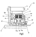
- FIG. 3 another alternative embodiment of a dual clutch assembly 14b is shown. This corresponds in terms of design and operation generally the dual clutch assembly 14a of Fig. 2. In the following, only differences will be discussed.
- the dual-clutch arrangement 14b has a first friction clutch 26b and a second friction clutch 24, which are arranged radially nested one inside the other.
- the first friction clutch 26b is disposed radially outward.
- a plate carrier 40, 46 serves at the same time as an inner disk carrier 46 for the first friction clutch 26b and as an outer disk carrier 40 for the second friction clutch 24.
- a second rotary feedthrough is provided to the pressure chamber 54 for the second friction clutch 24, via the shaft portion 66th
- FIGS. 4 and 5 show two further embodiments of dual clutch arrangements 14c, 14d.
- a hub 64 ' is provided which extends axially inwardly from the input side of the dual clutch assembly.
- connection on the input side of the dual clutch assembly 14c, 14d is somewhat more expensive.
- For the fluid supply can usually be realized with a simple rotary feedthrough.
- the dual-clutch arrangement 14c shown in FIG. 4 has two friction clutches nested radially one inside the other, the first friction clutch 26c being arranged radially on the outside.
- the friction clutches are arranged axially adjacent to one another, wherein the first friction clutch 26d is arranged on the input side.
- the shaft portion 66 While in the dual clutch assemblies 14a, 14b, the shaft portion 66 is assigned to each of the output side, in particular connected to the other transmission input shaft 27, in the dual clutch assemblies 14c, 14d, the shaft portion 66 'associated with the input. In other words, it is possible that the input members of the friction clutches 24, 26c and 26d rotate with the shaft portion 66 ', so that only a simple rotary feedthrough from the hub 64' to the shaft portion 66 'is required.
Abstract
Description
- Die vorliegende Erfindung betrifft eine Doppelkupplungsanordnung mit einer Eingangswelle, mit einer ersten Reibkupplung, deren Eingangsglied mit der Eingangswelle und deren Ausgangsglied mit einer ersten Ausgangswelle verbunden ist, mit einer zweiten Reibkupplung, deren Eingangsglied mit der Eingangswelle und deren Ausgangsglied mit einer zweiten Ausgangswelle verbunden ist, wobei die Ausgangswellen mit entsprechenden Eingangswellen eines Doppelkupplungsgetriebes verbindbar sind, und mit einer elektrischen Maschine, die mit der ersten Ausgangswelle verbunden ist.
- Eine derartige Doppelkupplungsanordnung ist bekannt aus dem Dokument
DE 10 2004 062 530 A1 - Doppelkupplungsanordnungen für Doppelkupplungsgetriebe sind allgemein bekannt. Bei einem Doppelkupplungsgetriebe sind die Gangstufen auf zwei parallele Teilgetriebe verteilt, und zwar derart, dass einem Teilgetriebe die ungeraden Gangstufen und dem anderen Teilgetriebe die geraden Gangstufen zugeordnet sind. Jedem Teilgetriebe ist ferner eingangsseitig eine eigene Reibkupplung zugeordnet. Die zwei Reibkupplungen bilden eine Doppelkupplungsanordnung, die zwischen einem Antriebsmotor (gewöhnlich einem Verbrennungsmotor) und dem Doppelkupplungsgetriebe angeordnet ist.
- Wenn in einem Teilgetriebe eine Gangstufe eingelegt ist und die zugeordnete Reibkupplung geschlossen ist, kann in dem anderen Teilgetriebe eine benachbarte Gangstufe bereits eingelegt werden. Mit Auslegen und Öffnen der Reibkupplung der Quellgangstufe wird in überschneidender Art und Weise die Reibkupplung der Zielgangstufe geschlossen, so dass ein Gangwechsel ohne Zugkraftunterbrechung erfolgen kann.
- Das Grundprinzip solcher Doppelkupplungsgetriebe ist seit langem bekannt. In jüngster Zeit hat diese Technologie wieder eine größere Bedeutung erlangt.
- Bei dem Doppelkupplungsgetriebe, das aus der eingangs genannten
DE 10 2004 062 530 A1 bekannt geworden ist, ist an das Doppelkupplungsgetriebe ferner eine elektrische Maschine angebunden. Die elektrische Maschine ist, genauer gesagt, über einen Radsatz mit der ersten Ausgangswelle verbunden. Die elektrische Maschine ist parallel zu der koaxialen Anordnung der Reibkupplungen gelagert. - Aus der
EP 1 541 401 A1 ist eine Kupplungsanordnung bekannt, die für einen Hybrid-Antriebsstrang verwendbar ist. Das Getriebe des Antriebsstanges ist ein herkömmliches Getriebe mit einer Mehrzahl von Gangstufen, dem gewöhnlich eine einzelne Anfahr- und Trennkupplung zugeordnet ist, die zwischen Antriebsmotor und Getriebe angeordnet wird. - Bei der dort beschriebenen Kupplungsanordnung sind zwei Reibkupplungen nicht parallel sondern seriell miteinander verbunden, und zwar über eine elektrische Maschine. Mit anderen Worten ist das Ausgangsglied der einen Reibkupplung mit der elektrischen Maschine verbunden. Ferner ist die elektrische Maschine mit dem Eingangsglied der anderen Reibkupplung verbunden.
- Aus der
EP 1 195 537 B1 ist schließlich eine herkömmliche Doppelkupplungsanordnung bekannt. - Vor dem obigen Hintergrund ist es die Aufgabe der vorliegenden Erfindung, eine verbesserte Doppelkupplungsanordnung anzugeben.
- Diese Aufgabe wird bei der eingangs genannten Doppelkupplungsanordnung dadurch gelöst, dass die elektrische Maschine koaxial zu der ersten Reibkupplung angeordnet ist.
- Durch die koaxiale Anordnung der elektrischen Maschine ist es möglich, die elektrische Maschine optimal in die Doppelkupplungsanordnung zu integrieren. Das Gehäuse des eigentlichen Doppelkupplungsgetriebes kann vereinfacht werden. Ferner ist eine modulare Ausgestaltung der Doppelkupplungsanordnung vergleichsweise einfach realisierbar, derart, dass sowohl Doppelkupplungsanordnungen mit als auch ohne elektrische Maschine für unterschiedliche Produktvarianten realisierbar sind.
- Die Aufgabe wird somit vollkommen gelöst.
- Generell ist anzumerken, dass die erste Reibkupplung sowohl dem Teilgetriebe mit den ungeraden Gangstufen als auch dem Teilgetriebe mit den geraden Gangstufen zugeordnet sein kann. Die Unterscheidung zwischen erster und zweiter Reibkupplung erfolgt vorliegend lediglich zur besseren Darstellbarkeit der Erfindung.
- Von besonderem Vorteil ist es, wenn ein Rotor der elektrischen Maschine fest mit dem Ausgangsglied der ersten Reibkupplung verbunden ist.
- Bei dieser Ausführungsform ist eine vollwertige Doppelkupplungsanordnung mit direkter Anbindung an eine Getriebeeingangswelle ohne zwischengeschaltete Drehmomentübertragungseinrichtung möglich.
- Von besonderem Vorteil ist es, wenn der Rotor und das Ausgangsglied der ersten Reibkupplung einstückig ausgebildet sind.
- Bei dieser Ausführungsform lässt sich die Doppelkupplungsanordnung mit wenigen Bauteilen realisieren.
- Gemäß einer weiteren bevorzugten Ausführungsform ist der Rotor radial außen an dem Ausgangsglied der ersten Reibkupplung festgelegt.
- Bei dieser Ausführungsform lässt sich eine modulare Doppelkupplungsanordnung besonders einfach realisieren, da die elektrische Maschine radial außerhalb der Reibkupplungen angeordnet werden kann.
- Ferner ist es vorteilhaft, wenn die erste Reibkupplung eine Lamellenkupplung ist und wenn das Ausgangsglied der ersten Reibkupplung ein Außenlamellenträger ist.
- Auch hierbei ist es möglich, eine elektrische Maschine in einen Doppelkupplungsgetriebe-Antriebsstrang zu integrieren, ohne gravierende Änderungen am mechanischen Aufbau und/oder der Steuerung.
- Gemäß einer weiteren bevorzugten Ausführungsform sind die erste und die zweite Reibkupplung axial nebeneinander angeordnet.
- Hierdurch lässt sich eine radial kompakte Bauform realisieren.
- Von besonderem Vorteil ist es dabei, wenn die erste Reibkupplung ausgangsseitig angeordnet ist.
- Dabei lässt sich das Ausgangsglied der ersten Reibkupplung konstruktiv besonders einfach mit der ersten Ausgangswelle (= erste Getriebeeingangswelle) verbinden.
- Alternativ ist es auch möglich, die erste Reibkupplung eingangsseitig anzuordnen.
- Dies ermöglicht insgesamt eine konstruktive Vereinfachung des Gesamtaufbaus.
- Die Begriffe eingangsseitig und ausgangsseitig sollen vorliegend so verstanden werden, dass die eine Reibkupplung in axialer Richtung näher am Eingang bzw. Ausgang angeordnet ist, sind also rein räumlich zu verstehen.
- Gemäß einer weiteren bevorzugten Ausführungsform sind die erste und die zweite Reibkupplung radial ineinander verschachtelt angeordnet.
- Bei dieser Ausführungsform lässt sich eine axial kompakte Bauform realisieren.
- Dabei ist es von besonderem Vorteil, wenn die erste Reibkupplung radial außen angeordnet ist.
- Auf diese Weise kann die Verbindung mit der elektrischen Maschine konstruktiv besonders einfach realisiert werden.
- Bei der radial ineinander verschachtelten Anordnung der Reibkupplungen ist es ferner bevorzugt, wenn die Reibkupplungen jeweils als Lamellenkupplungen ausgebildet sind und wenn ein Lamellenträger sowohl einen Innenlamellenträger der einen Reibkupplung als auch einen Außenlamellenträger der anderen Reibkupplung bildet.
- Dies ermöglicht eine Konstruktion der Doppelkupplungsanordnung mit wenigen Bauteilen.
- Insgesamt ist es ferner bevorzugt, wenn die Reibkupplungen als nass laufende Reibkupplungen ausgebildet sind und wenn radial innerhalb der Reibkupplungen eine gehäusefeste Nabe angeordnet ist, über die den Reibkupplungen Fluid zuführbar ist.
- Das Zuführen von Fluid kann dabei sowohl zur Betätigung der Reibkupplungen dienen, als auch zum Kühlen der Reibkupplungen. Es versteht sich, dass zu diesem Zweck bevorzugt getrennte Fluidpfade eingerichtet werden. Diese können über eine solche Nabe konstruktiv besonders günstig eingerichtet werden.
- Generell ist die Nabe radial innerhalb der Reibkupplungen angeordnet. Dies bedeutet jedoch nicht notwendigerweise, dass sich die Nabe über die gesamte axiale Länge der Reibkupplungen erstrecken muss. Die Nabe kann sich auch lediglich in eine der zwei Reibkupplungen hinein erstrecken, oder in einen Abschnitt einer Reibkupplung. Die weitere Verteilung von Fluid kann dann über geeignete Gehäuse- bzw. Käfigbauteile der Reibkupplungen erfolgen.
- Von besonderem Vorteil ist es, wenn sich die gehäusefeste Nabe von der Ausgangsseite her radial in die Reibkupplungen hinein erstreckt.
- Bei dieser Ausführungsform ist die Doppelkupplungsanordnung auf der Eingangsseite konstruktiv besonders einfach mit einem Antriebsmotor verbindbar.
- Bei einer alternativen Ausführungsform ist die gehäusefeste Nabe an der Eingangsseite angeordnet und erstreckt sich von der Eingangsseite her in die Reibkupplungen hinein.
- Bei dieser Ausführungsform kann eine Drehdurchführung zum Zuführen von Fluid über die Nabe besonders einfach realisiert werden.
- Generell ist Folgendes anzumerken: Die elektrische Maschine kann als Motor oder als Generator verwendet werden, je nach Betriebsmodus. Durch die koaxiale Bauweise und die bevorzugte Verwendung von Bauteilen der Reibkupplungen für die Anbindung der elektrischen Maschine ist eine Bauraum sparende Anordnung möglich. Es lässt sich mehr als eine einzelne feste Übersetzung von der elektrischen Maschine zu dem Hauptantrieb bzw. zum Getriebeabtrieb einrichten (in Abhängigkeit von der Anzahl der Gangstufen des zugeordneten Teilgetriebes). Mit der Anbindung der elektrischen Maschine an das Ausgangsglied von einer der zwei Reibkupplungen (im vorliegenden Sprachgebrauch die erste Reibkupplung) sind sämtliche Vorteile der Hybridtechnologie realisierbar, einschließlich Rekuperation, Boost-Betrieb, Motorstart/stopp-Automatik, etc.
- Erfindungsgemäß lässt sich die elektrische Maschine auch in ein vorhandenes Doppelkupplungsgetriebesystem integrieren, ohne gravierende Änderungen am mechanischen Aufbau oder der Steuerung. Die Doppelkupplungsanordnung kann konstruktiv auf einfache Weise so realisiert sein, dass eine Einbindung in einen Antriebsstrang mit oder ohne elektrische Maschine möglich ist.
- Die Steuerung der Doppelkupplungsanordnung kann hydraulisch, elektrisch oder elektromechanisch ausgeführt werden.
- Ferner versteht sich, dass ein mechanischer Antrieb einer Pumpe und weiterer Nebenaggregate möglich ist.
- Es versteht sich, dass die vorstehend genannten und die nachstehend noch zu erläuternden Merkmale nicht nur in der jeweils angegebenen Kombination, sondern auch in anderen Kombinationen oder in Alleinstellung verwendbar sind, ohne den Rahmen der vorliegenden Erfindung zu verlassen.
- Ausführungsbeispiele der Erfindung sind in der Zeichnung dargestellt und werden in der nachfolgenden Beschreibung näher erläutert. Es zeigen:
- Fig. 1
- eine schematische Darstellung eines Antriebsstranges für ein Kraftfahrzeug mit einer Ausführungsform einer erfindungsgemäßen Doppelkupplungsanordnung;
- Fig. 2
- eine Halbschnittansicht durch eine weitere Ausführungsform einer erfindungsgemäßen Doppelkupplungsanordnung;
- Fig. 3
- eine Halbschnittansicht einer weiteren Ausführungsform einer erfindungsgemäßen Doppelkupplungsanordnung;
- Fig. 4
- eine Halbschnittansicht einer weiteren Ausführungsform einer erfindungsgemäßen Doppelkupplungsanordnung; und
- Fig. 5
- eine Halbschnittansicht einer weiteren Ausführungsform einer erfindungsgemäßen Doppelkupplungsanordnung.
- In Fig. 1 ist ein Antriebsstrang für ein Kraftfahrzeug generell mit 10 bezeichnet.
- Der Antriebsstrang 10 ist als Doppelkupplungsgetriebe-Antriebsstrang ausgebildet und beinhaltet einen Antriebsmotor 12, in der Regel einen Verbrennungsmotor. Ferner weist der Antriebsstrang 10 eine Doppelkupplungsanordnung 14 auf, deren Eingang mit einer Motorabtriebswelle 13 verbunden ist.
- Der Antriebsstrang 10 weist ein Doppelkupplungsgetriebe 16 auf, das zwei parallele Teilgetriebe beinhaltet. Auch beinhaltet der Antriebsstrang 10 ein Differential 18, das mit dem Ausgang des Doppelkupplungsgetriebes 16 verbunden und dazu ausgelegt ist, Antriebsleistung auf zwei angetriebene Räder des Kraftfahrzeugs zu verteilen.
- Obgleich unter einem Doppelkupplungsgetriebe im allgemeinen Sprachgebrauch eine Kombination aus zwei parallelen Teilgetrieben und einer Doppelkupplungsanordnung verstanden wird, wird der Begriff Doppelkupplungsgetriebe vorliegend im Sinne eines Getriebes mit zwei Teilgetrieben zur Verbindung mit einer Doppelkupplungsanordnung verwendet.
- Das Doppelkupplungsgetriebe 16 beinhaltet eine Mehrzahl von Radsätzen für eine entsprechende Mehrzahl von Gangstufen (z.B. 5, 6 oder mehr Gangstufen). Im vorliegenden Fall sind aus Gründen einer übersichtlichen Darstellung lediglich ein Radsatz 20 für eine erste Gangstufe und ein Radsatz 22 für eine zweite Gangstufe gezeigt. Die Radsätze 20, 22 sind unterschiedlichen Teilgetrieben zugeordnet. Der Radsatz 20 ist mittels einer ersten Schaltkupplung 21 in den Leistungsübertragungspfad schaltbar. Der Radsatz 22 ist mittels einer zweiten Schaltkupplung 23 in den Leistungsübertragungspfad schaltbar bzw. ein- und auslegbar.
- Die Darstellung des Doppelkupplungsgetriebes 16 mit einer Vorgelegewelle, die gleichzeitig eine Ausgangswelle bildet, ist lediglich beispielhaft zu verstehen.
- Die erfindungsgemäße Doppelkupplungsanordnung ist für jede Art von Doppelkupplungsgetriebe-Antriebsstrang verwendbar, sei es für den Längs- oder Quereinbau, für Front-, Heck- oder Mittelmotorvarianten.
- Die Doppelkupplungsanordnung 14 weist eine erste Reibkupplung in Form einer Lamellenkupplung 26 und eine zweite Kupplung in Form einer Lamellenkupplung 24 auf.
- Die zweite Kupplung 24 ist eingangsseitig mit der Motorabtriebswelle 13 verbunden. Ausgangsseitig ist die zweite Kupplung 24 mit einer Ausgangswelle (zweite Ausgangswelle) verbunden. Die zweite Ausgangswelle ist mit einer Getriebeeingangswelle 25 (Innenwelle) verbunden, die dem Teilgetriebe mit den ungeraden Gangstufen zugeordnet ist.
- Die erste Reibkupplung 26 ist eingangsseitig ebenfalls mit der Motorabtriebswelle 13 verbunden. Ausgangsseitig ist die erste Reibkupplung 26 (über eine erste Ausgangswelle) mit einer weiteren Getriebeeingangswelle 27 verbunden, die koaxial als Hohlwelle um die andere Getriebeeingangswelle 25 herum vorgesehen ist. Die weitere Getriebeeingangswelle 27 ist dem zweiten Teilgetriebe des Doppelkupplungsgetriebes 16 zugeordnet, das die geraden Gangstufen aufweist.
- Koaxial zu der Doppelkupplungsanordnung 14 ist eine elektrische Maschine 30 vorgesehen. Ein Rotor 32 der elektrischen Maschine 30 ist mit einem Ausgangsglied der ersten Reibkupplung 26 verbunden. Ein Stator 34 der elektrischen Maschine 30 ist gehäusefest angeordnet (Gehäuse 36).
- Im vorliegenden Fall ist die elektrische Maschine 30 radial außerhalb der Doppelkupplungsanordnung 14 angeordnet. Es ist jedoch auch möglich, die elektrische Maschine 30 koaxial zu der als Hohlwelle ausgebildeten Getriebeeingangswelle 27 anzuordnen, derart, dass der Rotor der elektrischen Maschine 30 unmittelbar mit der Hohlwelle 27 verbunden ist.
- Die Reibkupplungen 24, 26 sind, wie gesagt, als Lamellenkupplungen ausgebildet. Die zweite Reibkupplung 24 weist als Eingangsglied einen Außenlamellenträger 40 auf. Ein Innenlamellenträger 42 der zweiten Reibkupplung 24 ist mit der einen Getriebeeingangswelle 25 (Innenwelle) verbunden.
- Ein Eingangsglied der ersten Reibkupplung 26 ist als Innenlamellenträger 46 ausgebildet. Der Innenlamellenträger 46 kann einerseits direkt mit der Motorabtriebswelle 13 verbunden sein. Der Innenlamellenträger 46 kann jedoch andererseits, wie gezeigt, auch mit dem Außenlamellenträger 40 der zweiten Reibkupplung 24 verbunden sein (mittelbar mit der Motorabtriebswelle 13 verbunden).
- Ein Ausgangsglied der ersten Reibkupplung 26 ist als Außenlamellenträger 44 ausgebildet. Der Rotor 32 ist mit dem Außenlamellenträger 44 fest verbunden oder vorzugsweise sogar einstückig mit diesem ausgebildet.
- Der Außenlamellenträger 44 ist mit der weiteren Getriebeeingangswelle 27 (Hohlwelle) verbunden.
- Da die elektrische Maschine 30 radial außerhalb der Doppelkupplungsanordnung 14 angeordnet ist, lässt sich der Antriebsstrang 10 konstruktiv einfach sowohl mit elektrischer Maschine als auch ohne elektrische Maschine realisieren (modulare Bauweise).
- Ferner ist eine Integration in vorhandene Doppelkupplungsgetriebesysteme möglich.
- Durch die Anbindung der elektrischen Maschine an eine der Getriebeeingangswellen ist ein optimierter Hybridbetrieb möglich. Es sind unterschiedliche Übersetzungen von der elektrischen Maschine zum Getriebeabtrieb bzw. zum Antriebsmotor realisierbar (über die Gangstufen des Teilgetriebes, das der ersten Reibkupplung 26 zugeordnet ist).
- Ein weiterer Vorteil der radial außen liegenden Anordnung besteht darin, dass bei nass laufenden Reibkupplungen 24, 26 die elektrische Maschine 30 in den Kühlkreislauf der Doppelkupplungsanordnung einbezogen werden kann.
- Das Kühlfluid wird bei Doppelkupplungsanordnungen generell von radial innen zugeführt und drängt durch die Fliehkraft radial nach außen. Daher kann das so verwendete Kühlfluid auch dazu verwendet werden, die radial außen liegende elektrische Maschine zu kühlen, insbesondere den Stator.
- In den folgenden Figuren 2 bis 5 sind unterschiedliche Ausführungsformen der erfindungsgemäßen Doppelkupplungsanordnung gezeigt.
- Der generelle Aufbau und die generelle Funktionsweise dieser Doppelkupplungsanordnungen entsprechen generell der Doppelkupplungsanordnung 14 bzw. deren Einbindung in den Antriebsstrang 10 der Fig. 1. Im Folgenden wird daher lediglich auf einige konstruktive Details bzw. Modifikationen eingegangen.
- In Fig. 2 ist eine Doppelkupplungsanordnung 14a gezeigt, bei der die Reibkupplungen 24, 26a axial hintereinander bzw. nebeneinander angeordnet sind.
- Die zweite Reibkupplung 24 ist eingangsseitig und die erste Reibkupplung 26a ist ausgangsseitig angeordnet. Die Aktuatorik zum Betätigen der Reibkupplungen 24, 26a ist radial innen liegend angeordnet.
- Ein Kolben der zweiten Reibkupplung 24 ist bei 50 gezeigt. Ein Kolben der ersten Reibkupplung 26a ist bei 52 gezeigt. Ein Druckraum der zweiten Reibkupplung 24 ist bei 54 gezeigt. In den Druckraum 54 ist Hydraulikfluid zum Betätigen der Reibkupplung 24 zuführbar, wie es durch einen Pfeil P24 schematisch angedeutet ist. Ein Druckraum der ersten Reibkupplung 26a ist bei 56 gezeigt. In diesen ist zum Betätigen der ersten Reibkupplung 26a Hydraulikfluid zuführbar, wie es durch einen Pfeil P26 gezeigt ist.
- Der zweiten Reibkupplung 24 ist ferner ein Ausgleichsraum 58 zugeordnet, in den Hydraulikfluid einführbar ist, um die auf den Kolben 50 wirkenden Kräfte kompensieren zu können, die aufgrund der auf das Hydraulikfluid in dem Druckraum 54 wirkenden Fliehkraft entstehen. Ein entsprechender Ausgleichsraum für die erste Reibkupplung 26a ist bei 60 gezeigt.
- In den Ausgleichsräumen 58, 60 sind ferner nicht näher bezeichnete Federn zum Rückstellen der Kolben 50, 52 angeordnet.
- Radial innerhalb der Reibkupplungen 24, 26a ist eine gehäusefeste Nabe 64 angeordnet. Die gehäusefeste Nabe 64 erstreckt sich ausgehend von der Ausgangsseite der Doppelkupplungsanordnung 14a axial in die Doppelkupplungsanordnung 14a hinein. Über die Nabe 64 kann Hydraulikfluid über verschiedene Kanäle zugeführt werden, zum Zuführen von Hydraulikfluid P24 zu dem Druckraum 54, von Hydraulikfluid P26 zu dem Druckraum 56, und zum Zuführen von Ausgleichs- und Kühlfluid AK zu den Ausgleichsräumen 58, 60.
- Die Ausgleichsräume 58, 60 sind über (nicht dargestellte) Öffnungen in den Kupplungsbauteilen dazu ausgelegt, die Reibkupplungen 24, 26a mit Kühlfluid zu versorgen. Das Kühlfluid kann dann ferner radial nach außen geführt werden, und zwar hin zu der elektrischen Maschine 30 (dem Stator 34).
- Die Nabe 64 bildet hierbei einen Teil einer Drehdurchführung. Der rotierende Teil der Drehdurchführung ist durch ein Wellenteil 66 gebildet. Dieses ist zum einen mit dem Außenlamellenträger 44 der ersten Reibkupplung 26a verbunden. Zum anderen ist das Wellenteil 66 mit der weiteren Getriebeeingangswelle 27 verbindbar, wie es in Fig. 2 schematisch angedeutet ist.
- Das Wellenteil 66 bildet ferner hin zu dem Druckraum 54 eine weitere Drehdurchführung. Hierdurch ist es möglich, die Fluidzufuhr zu der Doppelkupplungsanordnung 14a von der Ausgangsseite her zu realisieren. Daher ist eine Anbindung an die Motorabtriebswelle 13 auf konstruktiv einfache Weise möglich.
- In Fig. 3 ist eine weitere alternative Ausführungsform einer Doppelkupplungsanordnung 14b gezeigt. Diese entspricht hinsichtlich Aufbau und Funktionsweise generell der Doppelkupplungsanordnung 14a der Fig. 2. Im Folgenden wird lediglich auf Unterschiede eingegangen.
- Die Doppelkupplungsanordnung 14b weist eine erste Reibkupplung 26b und eine zweite Reibkupplung 24 auf, die radial ineinander verschachtelt angeordnet sind. Die erste Reibkupplung 26b ist radial außen angeordnet.
- Ein Lamellenträger 40, 46 dient gleichzeitig als Innenlamellenträger 46 für die erste Reibkupplung 26b und als Außenlamellenträger 40 für die zweite Reibkupplung 24.
- Wiederum ist eine zweite Drehdurchführung hin zu dem Druckraum 54 für die zweite Reibkupplung 24 vorgesehen, und zwar über das Wellenteil 66.
- In den Fig. 4 und 5 sind zwei weitere Ausführungsformen von Doppelkupplungsanordnungen 14c, 14d gezeigt.
- In beiden Fällen ist eine Nabe 64' vorgesehen, die sich von der Eingangsseite der Doppelkupplungsanordnung her axial nach innen erstreckt.
- Bei diesen Ausführungsformen ist die Anbindung auf der Eingangsseite der Doppelkupplungsanordnung 14c, 14d etwas aufwändiger. Dafür lässt sich die Fluidversorgung in der Regel mit einer einfachen Drehdurchführung realisieren.
- Die in Fig. 4 gezeigte Doppelkupplungsanordnung 14c weist zwei radial ineinander verschachtelte Reibkupplungen auf, wobei die erste Reibkupplung 26c radial außen angeordnet ist.
- Bei der Doppelkupplungsanordnung 14d der Fig. 5 sind die Reibkupplungen axial benachbart zueinander angeordnet, wobei die erste Reibkupplung 26d eingangsseitig angeordnet ist.
- Während bei den Doppelkupplungsanordnungen 14a, 14b das Wellenteil 66 jeweils der Ausgangsseite zugeordnet ist, insbesondere mit der weiteren Getriebeeingangswelle 27 verbunden ist, ist bei den Doppelkupplungsanordnungen 14c, 14d das Wellenteil 66' dem Eingang zugeordnet. Mit anderen Worten ist es möglich, dass sich die Eingangsglieder der Reibkupplungen 24, 26c bzw. 26d mit dem Wellenteil 66' mitdrehen, so dass nur eine einfache Drehdurchführung von der Nabe 64' zu dem Wellenteil 66' erforderlich ist.
Claims (14)
- Doppelkupplungsanordnung (14) mit einer Eingangswelle (13), mit einer ersten Reibkupplung (26), deren Eingangsglied (46) mit der Eingangswelle (13) und deren Ausgangsglied (44) mit einer ersten Ausgangswelle (27) verbunden ist, mit einer zweiten Reibkupplung (24), deren Eingangsglied (40; 42d) mit der Eingangswelle (13) und deren Ausgangsglied (42; 40d) mit einer zweiten Ausgangswelle (25) verbunden ist, wobei die Ausgangswellen (25, 27) mit entsprechenden Eingangswellen eines Doppelkupplungsgetriebes (16) verbindbar sind, und mit einer elektrischen Maschine (30), die mit der ersten Ausgangswelle (27) verbunden ist,
dadurch gekennzeichnet, dass
die elektrische Maschine (30) koaxial zu der ersten Reibkupplung (26) angeordnet ist. - Doppelkupplungsanordnung nach Anspruch 1, dadurch gekennzeichnet, dass ein Rotor (32) der elektrischen Maschine (30) fest mit dem Ausgangsglied (44) der ersten Reibkupplung (26) verbunden ist.
- Doppelkupplungsanordnung nach Anspruch 2, dadurch gekennzeichnet, dass der Rotor (32) und das Ausgangsglied (44) der ersten Reibkupplung (26) einstückig ausgebildet sind.
- Doppelkupplungsanordnung nach Anspruch 2 oder 3, dadurch gekennzeichnet, dass der Rotor (32) radial außen an dem Ausgangsglied (44) der ersten Reibkupplung (26) festgelegt ist.
- Doppelkupplungsanordnung nach einem der Ansprüche 1 bis 4, dadurch gekennzeichnet, dass die erste Reibkupplung (26) eine Lamellenkupplung ist und dass das Ausgangsglied (44) der ersten Reibkupplung (26) ein Außenlamellenträger (44) ist.
- Doppelkupplungsanordnung nach einem der Ansprüche 1 bis 5, dadurch gekennzeichnet, dass die erste und die zweite Reibkupplung axial nebeneinander angeordnet sind.
- Doppelkupplungsanordnung nach Anspruch 6, dadurch gekennzeichnet, dass die erste Reibkupplung (26a) ausgangsseitig angeordnet ist.
- Doppelkupplungsanordnung nach Anspruch 6, dadurch gekennzeichnet, dass die erste Reibkupplung (26d) eingangsseitig angeordnet ist.
- Doppelkupplungsanordnung nach einem der Ansprüche 1 bis 5, dadurch gekennzeichnet, dass die erste und die zweite Reibkupplung radial ineinander verschachtelt angeordnet sind.
- Doppelkupplungsanordnung nach Anspruch 9, dadurch gekennzeichnet, dass die erste Reibkupplung (26b; 26c) radial außen angeordnet ist.
- Doppelkupplungsanordnung nach Anspruch 9 oder 10, dadurch gekennzeichnet, dass die erste und die zweite Reibkupplung jeweils als Lamellenkupplung ausgebildet sind und dass ein Lamellenträger einen Innenlamellenträger der einen Reibkupplung (26b; 26c) und einen Außenlamellenträger der anderen Reibkupplung bildet.
- Doppelkupplungsanordnung nach einem der Ansprüche 1 bis 11, dadurch gekennzeichnet, dass die Reibkupplungen als nasslaufende Reibkupplungen ausgebildet sind und dass radial innerhalb der Reibkupplungen eine gehäusefeste Nabe (64) angeordnet ist, über die den Reibkupplungen Fluid zuführbar ist.
- Doppelkupplungsanordnung nach Anspruch 12, dadurch gekennzeichnet, dass die gehäusefeste Nabe (64) sich von der Ausgangsseite her radial in die Reibkupplungen hinein erstreckt.
- Doppelkupplungsanordnung nach Anspruch 12, dadurch gekennzeichnet, dass die gehäusefeste Nabe (64') sich von der Eingangsseite her radial in die Reibkupplungen hinein erstreckt.
Applications Claiming Priority (1)
| Application Number | Priority Date | Filing Date | Title |
|---|---|---|---|
| DE102005063248A DE102005063248B4 (de) | 2005-12-21 | 2005-12-21 | Doppelkupplungsanordnung |
Publications (3)
| Publication Number | Publication Date |
|---|---|
| EP1800929A2 true EP1800929A2 (de) | 2007-06-27 |
| EP1800929A3 EP1800929A3 (de) | 2010-09-15 |
| EP1800929B1 EP1800929B1 (de) | 2013-08-28 |
Family
ID=37847240
Family Applications (1)
| Application Number | Title | Priority Date | Filing Date |
|---|---|---|---|
| EP06024765.7A Expired - Fee Related EP1800929B1 (de) | 2005-12-21 | 2006-11-30 | Doppelkupplungsanordnung |
Country Status (3)
| Country | Link |
|---|---|
| US (1) | US7832537B2 (de) |
| EP (1) | EP1800929B1 (de) |
| DE (1) | DE102005063248B4 (de) |
Cited By (21)
| Publication number | Priority date | Publication date | Assignee | Title |
|---|---|---|---|---|
| EP2011682A2 (de) * | 2007-06-29 | 2009-01-07 | Ford Global Technologies, LLC | Vorrichtung zur Leistungübertragung in ein Getriebe |
| WO2010007124A1 (de) * | 2008-07-17 | 2010-01-21 | Zf Friedrichshafen Ag | Verfahren zur kühlung einer elektrischen maschine in einem hvbridantriebsstrang eines kraftfahrzeugs |
| WO2011018291A1 (de) * | 2009-08-13 | 2011-02-17 | Zf Friedrichshafen Ag | Kraftfahrzeuggetriebe |
| WO2012021363A2 (en) | 2010-08-12 | 2012-02-16 | Borgwarner Inc. | Parallel dual clutch unit |
| EP2463136A1 (de) * | 2009-11-19 | 2012-06-13 | Aisin AW Co., Ltd. | Antriebsvorrichtung für ein fahrzeug |
| US8838366B2 (en) | 2010-03-05 | 2014-09-16 | Aisin Aw Co., Ltd. | Hybrid drive apparatus |
| US8836181B2 (en) | 2009-11-19 | 2014-09-16 | Aisin Aw Co., Ltd. | Vehicle drive device |
| US8836187B2 (en) | 2009-11-19 | 2014-09-16 | Aisin Aw Co., Ltd. | Vehicle drive device |
| US8997956B2 (en) | 2009-11-19 | 2015-04-07 | Aisin Aw Co., Ltd. | Vehicle drive device |
| WO2015126719A1 (en) | 2014-02-22 | 2015-08-27 | Borgwarner Inc. | Drivetrain for a motor vehicle, and method for operating a drivetrain of said type |
| US9140311B2 (en) | 2010-03-05 | 2015-09-22 | Aisin Aw Co., Ltd. | Vehicle driving apparatus |
| WO2017186226A1 (de) * | 2016-04-27 | 2017-11-02 | Schaeffler Technologies AG & Co. KG | Hybridmodul und antriebsanordnung für ein kraftfahrzeug |
| EP3273083A1 (de) * | 2012-07-12 | 2018-01-24 | GETRAG B.V. & Co. KG | Lamellenträger-lageranordnung und kupplungsanordnung für einen kraftfahrzeugantriebsstrang |
| WO2019063226A1 (de) * | 2017-09-27 | 2019-04-04 | Daimler Ag | Hybridgetriebe und hybridantriebssystem damit |
| CN109986948A (zh) * | 2017-12-29 | 2019-07-09 | 比亚迪股份有限公司 | 混合动力驱动系统及车辆 |
| WO2020020401A3 (de) * | 2018-07-26 | 2020-04-23 | Schaeffler Technologies AG & Co. KG | Hybridgetriebe, hybrid-antriebsanordnung und verfahren zum betreiben einer hybrid-antriebsanordnung |
| EP3670963A1 (de) * | 2018-12-20 | 2020-06-24 | Ningbo Geely Automobile Research & Development Co. Ltd. | Getriebe für ein fahrzeug |
| DE102020001095A1 (de) | 2020-02-20 | 2021-08-26 | Daimler Ag | Doppelkupplungsgetriebe |
| WO2021164993A1 (de) | 2020-02-20 | 2021-08-26 | Daimler Ag | Doppelkupplungsgetriebe |
| WO2021164991A1 (de) | 2020-02-20 | 2021-08-26 | Daimler Ag | Doppelkupplungsgetriebe |
| DE102020001094A1 (de) | 2020-02-20 | 2021-08-26 | Daimler Ag | Doppelkupplungsgetriebe |
Families Citing this family (51)
| Publication number | Priority date | Publication date | Assignee | Title |
|---|---|---|---|---|
| FR2871106B1 (fr) * | 2004-06-03 | 2007-10-05 | Peugeot Citroen Automobiles Sa | Element de transmission a double embrayage pour chaine de traction hybride de vehicule automobile, procede de montage, et vehicule automobile equipe d'un tel element |
| DE102007008946C5 (de) | 2006-02-27 | 2021-10-07 | Borgwarner Inc. | Mehrfachkupplung für ein Fahrzeug mit einem Hybridantrieb |
| DE102006040117A1 (de) * | 2006-08-26 | 2008-03-27 | Zf Friedrichshafen Ag | Hybridantriebseinheit |
| DE102006058947A1 (de) * | 2006-12-14 | 2008-06-19 | Dr.Ing.H.C. F. Porsche Ag | Doppelkupplung für einen Hybrid-Antrieb |
| DE102007050236A1 (de) * | 2007-10-20 | 2009-04-23 | Zf Friedrichshafen Ag | Antriebssystem für ein Fahrzeug |
| DE102009016282B4 (de) * | 2008-04-04 | 2013-11-21 | GM Global Technology Operations LLC (n. d. Ges. d. Staates Delaware) | Zweifach wirkende Kupplungsvorrichtung für kompaktes elektromechanisches Getriebe |
| US8221279B2 (en) * | 2008-04-04 | 2012-07-17 | GM Global Technology Operations LLC | Dual apply clutch apparatus for compact electro-mechanical transmission |
| DE102008060580B4 (de) * | 2008-06-03 | 2021-01-21 | Borgwarner Inc. | Mehrfach-Kupplungseinrichtung mit zwei Druckausgleichsräumen |
| US8322504B2 (en) * | 2008-08-14 | 2012-12-04 | Schaeffler Technologies AG & Co. KG | Combined power transmission, drive unit and drive train for a hybrid system |
| JP5131153B2 (ja) * | 2008-10-28 | 2013-01-30 | アイシン・エィ・ダブリュ株式会社 | 車両用駆動装置 |
| JP5157823B2 (ja) * | 2008-10-28 | 2013-03-06 | アイシン・エィ・ダブリュ株式会社 | 車両用駆動装置 |
| JP5042973B2 (ja) * | 2008-12-01 | 2012-10-03 | 本田技研工業株式会社 | ハイブリッド車両用動力伝達装置 |
| DE102009006422B4 (de) * | 2009-01-22 | 2011-02-10 | Getrag Getriebe- Und Zahnradfabrik Hermann Hagenmeyer Gmbh & Cie Kg | Doppelkupplungsanordnung für Kraftfahrzeuge und Betätigungsverfahren hierfür |
| DE102011015376A1 (de) * | 2011-03-29 | 2012-10-04 | Daimler Ag | Hybridkraftfahrzeugvorrichtung |
| DE102011104279A1 (de) * | 2011-06-10 | 2012-12-13 | Getrag Getriebe- Und Zahnradfabrik Hermann Hagenmeyer Gmbh & Cie Kg | Kraftfahrzeug-Antriebsstrang |
| DE102011110444A1 (de) | 2011-08-11 | 2013-02-14 | Getrag Ford Transmissions Gmbh | Hybrid-Antriebsstrang |
| DE102011115286A1 (de) * | 2011-09-29 | 2013-04-04 | Borgwarner Inc. | Parallele Doppelkupplungseinrichtung |
| CN103264635B (zh) * | 2013-06-08 | 2015-08-19 | 长沙理工大学 | 一种双动力单轴输出的驱动系统 |
| DE102013022142A1 (de) * | 2013-12-19 | 2015-06-25 | Getrag Getriebe- Und Zahnradfabrik Hermann Hagenmeyer Gmbh & Cie Kg | Hybrid-Antriebsstrang für ein Kraftfahrzeug |
| WO2015113416A1 (en) | 2014-01-30 | 2015-08-06 | Byd Company Limited | Power transmission system for vehicle and vehicle comprising the same |
| WO2015113411A1 (en) | 2014-01-30 | 2015-08-06 | Byd Company Limited | Power transmission system for vehicle and vehicle comprising the same |
| US9944165B2 (en) | 2014-01-30 | 2018-04-17 | Byd Company Limited | Power transmission system for vehicle and vehicle comprising the same |
| CN104276031B (zh) | 2014-01-30 | 2016-01-13 | 比亚迪股份有限公司 | 车辆及其驱动控制方法 |
| CN104279311B (zh) | 2014-01-30 | 2015-11-25 | 比亚迪股份有限公司 | 车辆中同步器的控制方法及车辆 |
| WO2015113414A1 (en) | 2014-01-30 | 2015-08-06 | Byd Company Limited | Power transmission system for vehicle and vehicle comprising the same |
| EP3100886B1 (de) | 2014-01-30 | 2022-06-01 | BYD Company Limited | Fahrzeug und kraftübertragungssystem dafür |
| US10670123B2 (en) * | 2014-01-30 | 2020-06-02 | Byd Company Limited | Power transmission system for vehicle and vehicle comprising the same |
| JP2016033003A (ja) * | 2014-07-29 | 2016-03-10 | アイシン・エィ・ダブリュ株式会社 | ハイブリッド駆動装置 |
| WO2016037470A1 (en) | 2014-09-10 | 2016-03-17 | Byd Company Limited | Power transmission system and vehicle comprising the same |
| US9568066B2 (en) | 2014-09-10 | 2017-02-14 | Byd Company Limited | Power transmission system and vehicle comprising the same |
| WO2016037469A1 (en) | 2014-09-10 | 2016-03-17 | Byd Company Limited | Transmission unit, power transmission system and vehicle comprising the same |
| CN104608760B (zh) | 2014-10-20 | 2016-05-25 | 比亚迪股份有限公司 | 混合动力汽车及其换挡控制方法、动力传动系统 |
| WO2016112653A1 (en) | 2015-01-16 | 2016-07-21 | Byd Company Limited | Transmission unit, power transmission system and vehicle comprising the same |
| CN104773063B (zh) | 2015-01-16 | 2015-12-02 | 比亚迪股份有限公司 | 变速器、动力传动系统和车辆 |
| EP3245089B1 (de) | 2015-01-16 | 2021-07-28 | BYD Company Limited | Kraftübertragungssystem und fahrzeug damit |
| EP3245092B1 (de) | 2015-01-16 | 2022-05-04 | BYD Company Limited | Kraftübertragungssystem und fahrzeug damit |
| CN104691299A (zh) * | 2015-03-11 | 2015-06-10 | 昆山德拉特兰传动科技有限公司 | 多模式多挡位混合动力系统 |
| CN104709059A (zh) * | 2015-03-11 | 2015-06-17 | 昆山德拉特兰传动科技有限公司 | 用于纯电动车辆的电动力总成 |
| CN106143112B (zh) * | 2015-03-23 | 2018-11-06 | 比亚迪股份有限公司 | 动力传动系统以及具有其的车辆 |
| CN106555827A (zh) * | 2015-09-30 | 2017-04-05 | 上海汽车集团股份有限公司 | 汽车及其湿式双离合变速箱、湿式双离合器 |
| DE112017001268T5 (de) * | 2016-03-11 | 2018-11-29 | Borgwarner Inc. | Kupplung und Elektromotor |
| US10511207B2 (en) * | 2017-03-21 | 2019-12-17 | Borgwarner Inc. | Compact electric machine with combined rotor carrier and clutch housing |
| JP6531133B2 (ja) * | 2017-04-27 | 2019-06-12 | 本田技研工業株式会社 | ハイブリッド車両の駆動装置 |
| JP7031734B2 (ja) * | 2018-03-28 | 2022-03-08 | 株式会社アイシン | 車両用駆動装置 |
| EP3659844B1 (de) | 2018-11-29 | 2022-05-04 | Ningbo Geely Automobile Research & Development Co. Ltd. | Getriebe für ein fahrzeug |
| DE102020202786A1 (de) | 2019-03-14 | 2020-10-22 | Dana Automotive Systems Group, Llc | Mehrgang-schaltgetriebe mit einer getriebe-kupplung-baugruppe |
| DE102019212522B4 (de) * | 2019-08-21 | 2021-04-08 | Magna Pt B.V. & Co. Kg | Hybridgetriebe |
| CN110667366A (zh) * | 2019-10-10 | 2020-01-10 | 奇瑞汽车股份有限公司 | 一种专用于混合动力汽车的变速传动系统 |
| US11376942B2 (en) * | 2019-12-27 | 2022-07-05 | Schaeffler Technologies AG & Co. KG | Torque converter with sealed turbine shell and clutch cooling |
| KR102292261B1 (ko) * | 2020-02-04 | 2021-08-20 | 주식회사 카펙발레오 | 하이브리드 구동 모듈 |
| US11365793B2 (en) * | 2020-05-11 | 2022-06-21 | Schaeffler Technologies AG & Co. KG | Hybrid module including torque converter inside of e-motor and having remote compensation chamber |
Citations (3)
| Publication number | Priority date | Publication date | Assignee | Title |
|---|---|---|---|---|
| EP1195537A1 (de) | 2000-10-05 | 2002-04-10 | Ford Global Technologies, Inc., A subsidiary of Ford Motor Company | Doppelkupplung für ein Getriebe mit zwei Getriebeeingangswellen |
| EP1541401A1 (de) | 2003-12-13 | 2005-06-15 | BorgWarner Inc. | Doppelkupplungsübertragungselement für ein hybrides Fahrzeugsantriebssystem, Verfahren für den Aufbau des Elementes und Motorfahrzeug mit einem solchen Element |
| DE102004062530A1 (de) | 2003-12-24 | 2005-10-06 | Hyundai Motor Company | Doppelkupplungsgetriebe für ein Hybrid-Elektrofahrzeug und Verfahren zum Betreiben desselben |
Family Cites Families (8)
| Publication number | Priority date | Publication date | Assignee | Title |
|---|---|---|---|---|
| DE4323602A1 (de) * | 1993-07-09 | 1995-01-12 | Mannesmann Ag | Antriebsanordnung für ein Hybridfahrzeug |
| FR2799251B1 (fr) * | 1999-09-30 | 2006-12-08 | Mannesmann Sachs Ag | Installation d'embrayage multiple de cas echeant en combinaison avec un dispositif amortisseur d'oscillations de torsion ou/et une machine electrique |
| DE10165097B3 (de) * | 2000-07-18 | 2015-07-23 | Schaeffler Technologies AG & Co. KG | Doppelkupplungsgetriebe |
| FR2814121B1 (fr) * | 2000-09-19 | 2003-02-14 | Peugeot Citroen Automobiles Sa | Groupe motopropulseur pour un vehicule automobile a propulsion hybride |
| US20030089569A1 (en) * | 2000-11-17 | 2003-05-15 | Roumen Antonov | Trasmission devices, for ground vehicles and more particularly for molor-cars |
| FR2850906B1 (fr) * | 2003-02-06 | 2006-03-17 | Renault Sa | Boite de vitesses pour vehicule automobile et procede de changement de rapport de vitesses mis en oeuvre au moyen d'une telle boite de vitesses |
| JP4252400B2 (ja) * | 2003-08-25 | 2009-04-08 | 本田技研工業株式会社 | 車両用自動変速機の二重軸支持構造 |
| US7082850B2 (en) * | 2003-12-30 | 2006-08-01 | Eaton Corporation | Hybrid powertrain system |
-
2005
- 2005-12-21 DE DE102005063248A patent/DE102005063248B4/de active Active
-
2006
- 2006-11-30 EP EP06024765.7A patent/EP1800929B1/de not_active Expired - Fee Related
- 2006-12-14 US US11/638,788 patent/US7832537B2/en not_active Expired - Fee Related
Patent Citations (3)
| Publication number | Priority date | Publication date | Assignee | Title |
|---|---|---|---|---|
| EP1195537A1 (de) | 2000-10-05 | 2002-04-10 | Ford Global Technologies, Inc., A subsidiary of Ford Motor Company | Doppelkupplung für ein Getriebe mit zwei Getriebeeingangswellen |
| EP1541401A1 (de) | 2003-12-13 | 2005-06-15 | BorgWarner Inc. | Doppelkupplungsübertragungselement für ein hybrides Fahrzeugsantriebssystem, Verfahren für den Aufbau des Elementes und Motorfahrzeug mit einem solchen Element |
| DE102004062530A1 (de) | 2003-12-24 | 2005-10-06 | Hyundai Motor Company | Doppelkupplungsgetriebe für ein Hybrid-Elektrofahrzeug und Verfahren zum Betreiben desselben |
Cited By (40)
| Publication number | Priority date | Publication date | Assignee | Title |
|---|---|---|---|---|
| EP2011682A3 (de) * | 2007-06-29 | 2011-03-09 | Ford Global Technologies, LLC | Vorrichtung zur Leistungübertragung in ein Getriebe |
| EP2011682A2 (de) * | 2007-06-29 | 2009-01-07 | Ford Global Technologies, LLC | Vorrichtung zur Leistungübertragung in ein Getriebe |
| WO2010007124A1 (de) * | 2008-07-17 | 2010-01-21 | Zf Friedrichshafen Ag | Verfahren zur kühlung einer elektrischen maschine in einem hvbridantriebsstrang eines kraftfahrzeugs |
| US8863617B2 (en) | 2009-08-13 | 2014-10-21 | Zf Friedrichshafen Ag | Motor vehicle transmission |
| WO2011018291A1 (de) * | 2009-08-13 | 2011-02-17 | Zf Friedrichshafen Ag | Kraftfahrzeuggetriebe |
| EP2463136A1 (de) * | 2009-11-19 | 2012-06-13 | Aisin AW Co., Ltd. | Antriebsvorrichtung für ein fahrzeug |
| US8836181B2 (en) | 2009-11-19 | 2014-09-16 | Aisin Aw Co., Ltd. | Vehicle drive device |
| US8836187B2 (en) | 2009-11-19 | 2014-09-16 | Aisin Aw Co., Ltd. | Vehicle drive device |
| EP2463136A4 (de) * | 2009-11-19 | 2014-05-21 | Aisin Aw Co | Antriebsvorrichtung für ein fahrzeug |
| US8997956B2 (en) | 2009-11-19 | 2015-04-07 | Aisin Aw Co., Ltd. | Vehicle drive device |
| US8838366B2 (en) | 2010-03-05 | 2014-09-16 | Aisin Aw Co., Ltd. | Hybrid drive apparatus |
| US9140311B2 (en) | 2010-03-05 | 2015-09-22 | Aisin Aw Co., Ltd. | Vehicle driving apparatus |
| WO2012021363A2 (en) | 2010-08-12 | 2012-02-16 | Borgwarner Inc. | Parallel dual clutch unit |
| EP2603710A4 (de) * | 2010-08-12 | 2018-04-18 | Borgwarner Inc. | Parallele doppelkupplungsgetriebe-einheit |
| EP3273083A1 (de) * | 2012-07-12 | 2018-01-24 | GETRAG B.V. & Co. KG | Lamellenträger-lageranordnung und kupplungsanordnung für einen kraftfahrzeugantriebsstrang |
| WO2015126719A1 (en) | 2014-02-22 | 2015-08-27 | Borgwarner Inc. | Drivetrain for a motor vehicle, and method for operating a drivetrain of said type |
| WO2017186226A1 (de) * | 2016-04-27 | 2017-11-02 | Schaeffler Technologies AG & Co. KG | Hybridmodul und antriebsanordnung für ein kraftfahrzeug |
| US10843557B2 (en) | 2016-04-27 | 2020-11-24 | Schaeffler Technologies AG & Co. KG | Hybrid module and drive arrangement for a motor vehicle |
| WO2019063226A1 (de) * | 2017-09-27 | 2019-04-04 | Daimler Ag | Hybridgetriebe und hybridantriebssystem damit |
| CN109986948A (zh) * | 2017-12-29 | 2019-07-09 | 比亚迪股份有限公司 | 混合动力驱动系统及车辆 |
| WO2020020401A3 (de) * | 2018-07-26 | 2020-04-23 | Schaeffler Technologies AG & Co. KG | Hybridgetriebe, hybrid-antriebsanordnung und verfahren zum betreiben einer hybrid-antriebsanordnung |
| CN112469586A (zh) * | 2018-07-26 | 2021-03-09 | 舍弗勒技术股份两合公司 | 混合动力齿轮机构、混合动力驱动组件以及用于操作混合动力驱动组件的方法 |
| EP3670963A1 (de) * | 2018-12-20 | 2020-06-24 | Ningbo Geely Automobile Research & Development Co. Ltd. | Getriebe für ein fahrzeug |
| DE102020001095A1 (de) | 2020-02-20 | 2021-08-26 | Daimler Ag | Doppelkupplungsgetriebe |
| WO2021164993A1 (de) | 2020-02-20 | 2021-08-26 | Daimler Ag | Doppelkupplungsgetriebe |
| WO2021165029A1 (de) | 2020-02-20 | 2021-08-26 | Daimler Ag | Doppelkupplungsgetriebe |
| WO2021164991A1 (de) | 2020-02-20 | 2021-08-26 | Daimler Ag | Doppelkupplungsgetriebe |
| DE102020001094A1 (de) | 2020-02-20 | 2021-08-26 | Daimler Ag | Doppelkupplungsgetriebe |
| DE102020001100A1 (de) | 2020-02-20 | 2021-08-26 | Daimler Ag | Doppelkupplungsgetriebe |
| WO2021164990A1 (de) | 2020-02-20 | 2021-08-26 | Daimler Ag | Doppelkupplungsgetriebe |
| DE102020001099A1 (de) | 2020-02-20 | 2021-08-26 | Daimler Ag | Doppelkupplunsgetriebe |
| DE102020001095B4 (de) | 2020-02-20 | 2022-09-29 | Mercedes-Benz Group AG | Doppelkupplungsgetriebe |
| DE102020001094B4 (de) | 2020-02-20 | 2022-09-29 | Mercedes-Benz Group AG | Doppelkupplungsgetriebe |
| DE102020001100B4 (de) | 2020-02-20 | 2022-09-29 | Mercedes-Benz Group AG | Doppelkupplungsgetriebe |
| CN115135895A (zh) * | 2020-02-20 | 2022-09-30 | 梅赛德斯-奔驰集团股份公司 | 双离合变速器 |
| CN115135898A (zh) * | 2020-02-20 | 2022-09-30 | 梅赛德斯-奔驰集团股份公司 | 双离合变速器 |
| CN115135896A (zh) * | 2020-02-20 | 2022-09-30 | 梅赛德斯-奔驰集团股份公司 | 双离合变速器 |
| DE102020001099B4 (de) | 2020-02-20 | 2022-10-20 | Mercedes-Benz Group AG | Doppelkupplunsgetriebe |
| US11686354B2 (en) | 2020-02-20 | 2023-06-27 | Mercedes-Benz Group AG | Dual clutch transmission |
| US11732764B2 (en) | 2020-02-20 | 2023-08-22 | Mercedes-Benz Group AG | Dual clutch transmission |
Also Published As
| Publication number | Publication date |
|---|---|
| US7832537B2 (en) | 2010-11-16 |
| EP1800929B1 (de) | 2013-08-28 |
| US20070175723A1 (en) | 2007-08-02 |
| DE102005063248A1 (de) | 2007-07-12 |
| EP1800929A3 (de) | 2010-09-15 |
| DE102005063248B4 (de) | 2010-09-30 |
Similar Documents
| Publication | Publication Date | Title |
|---|---|---|
| EP1800929B1 (de) | Doppelkupplungsanordnung | |
| EP2662594B1 (de) | Doppelkupplungsgetriebe | |
| EP2517915B2 (de) | Hybrid-Antriebsstrang für ein Kraftfahrzeug | |
| DE102010010922B4 (de) | Parallele Doppelkupplungseinrichtung und Antriebsstrang mit einer solchen parallelen Doppelkupplungseinrichtung | |
| DE102013006429B4 (de) | Hybridantriebsanordnung für ein Kraftfahrzeug | |
| DE102009038344B4 (de) | Antriebsstrangmodul für ein Kraftfahrzeug | |
| EP2714448B1 (de) | Antriebsstrang für ein kraftfahrzeug | |
| EP3079238B1 (de) | Elektrische maschinenanordnung und kraftfahrzeuggetriebe | |
| EP1875096B1 (de) | Antriebseinheit für ein kraftfahrzeug | |
| DE102006061515A1 (de) | Doppelkupplungsgetriebe | |
| EP2605927B1 (de) | Kfz-antriebsstrang und verfahren zum betreiben eines antriebsstranges | |
| DE102011104279A1 (de) | Kraftfahrzeug-Antriebsstrang | |
| DE102013106896B4 (de) | Doppelkupplungsgetriebe | |
| DE102018203819A1 (de) | Hybridmodul mit einem Modulgehäuse | |
| DE102017121348A1 (de) | Kupplungseinrichtung, Hybridmodul und Antriebsstrang | |
| DE102017009024B4 (de) | Hybridgetriebe | |
| DE102012019971B4 (de) | Hybrid-Antriebsstrang für ein Kraftfahrzeug | |
| EP2916026A2 (de) | Doppelkupplungsanordnung | |
| EP3507518A1 (de) | Mehrfach-kupplung für ein kraftfahrzeug, insbesondere für einen hybridantrieb eines kraftfahrzeugs | |
| WO2020015927A1 (de) | Doppelkupplungsgetriebe | |
| DE102017204127A1 (de) | Doppelkupplungsgetriebeanordnung sowie Kraftfahrzeug | |
| DE102019202598B4 (de) | Doppelkupplungsgetriebe | |
| DE102017204126A1 (de) | Doppelkupplungsgetriebeanordnung sowie Kraftfahrzeug | |
| DE102016217597A1 (de) | Elektrische Achsenanordnung mit einer Fluidversorgung aus einer Wellenmitte | |
| DE102017111171A1 (de) | Hybridantriebsstrang |
Legal Events
| Date | Code | Title | Description |
|---|---|---|---|
| PUAI | Public reference made under article 153(3) epc to a published international application that has entered the european phase |
Free format text: ORIGINAL CODE: 0009012 |
|
| AK | Designated contracting states |
Kind code of ref document: A2 Designated state(s): AT BE BG CH CY CZ DE DK EE ES FI FR GB GR HU IE IS IT LI LT LU LV MC NL PL PT RO SE SI SK TR |
|
| AX | Request for extension of the european patent |
Extension state: AL BA HR MK YU |
|
| PUAL | Search report despatched |
Free format text: ORIGINAL CODE: 0009013 |
|
| AK | Designated contracting states |
Kind code of ref document: A3 Designated state(s): AT BE BG CH CY CZ DE DK EE ES FI FR GB GR HU IE IS IT LI LT LU LV MC NL PL PT RO SE SI SK TR |
|
| AX | Request for extension of the european patent |
Extension state: AL BA HR MK RS |
|
| 17P | Request for examination filed |
Effective date: 20110309 |
|
| AKX | Designation fees paid |
Designated state(s): FR IT |
|
| 17Q | First examination report despatched |
Effective date: 20110520 |
|
| REG | Reference to a national code |
Ref country code: DE Ref legal event code: R108 Effective date: 20110419 |
|
| GRAP | Despatch of communication of intention to grant a patent |
Free format text: ORIGINAL CODE: EPIDOSNIGR1 |
|
| REG | Reference to a national code |
Ref country code: DE Ref legal event code: R079 Free format text: PREVIOUS MAIN CLASS: B60K0006040000 Ipc: B60K0006387000 |
|
| RIC1 | Information provided on ipc code assigned before grant |
Ipc: B60K 6/26 20071001ALI20130326BHEP Ipc: B60K 6/40 20071001ALI20130326BHEP Ipc: B60K 6/48 20071001ALI20130326BHEP Ipc: B60K 6/387 20071001AFI20130326BHEP |
|
| GRAS | Grant fee paid |
Free format text: ORIGINAL CODE: EPIDOSNIGR3 |
|
| GRAA | (expected) grant |
Free format text: ORIGINAL CODE: 0009210 |
|
| AK | Designated contracting states |
Kind code of ref document: B1 Designated state(s): FR IT |
|
| PLBE | No opposition filed within time limit |
Free format text: ORIGINAL CODE: 0009261 |
|
| STAA | Information on the status of an ep patent application or granted ep patent |
Free format text: STATUS: NO OPPOSITION FILED WITHIN TIME LIMIT |
|
| 26N | No opposition filed |
Effective date: 20140530 |
|
| REG | Reference to a national code |
Ref country code: FR Ref legal event code: PLFP Year of fee payment: 10 |
|
| REG | Reference to a national code |
Ref country code: FR Ref legal event code: PLFP Year of fee payment: 11 |
|
| REG | Reference to a national code |
Ref country code: FR Ref legal event code: PLFP Year of fee payment: 12 |
|
| PGFP | Annual fee paid to national office [announced via postgrant information from national office to epo] |
Ref country code: IT Payment date: 20201124 Year of fee payment: 15 Ref country code: FR Payment date: 20201120 Year of fee payment: 15 |
|
| PG25 | Lapsed in a contracting state [announced via postgrant information from national office to epo] |
Ref country code: FR Free format text: LAPSE BECAUSE OF NON-PAYMENT OF DUE FEES Effective date: 20211130 |
|
| PG25 | Lapsed in a contracting state [announced via postgrant information from national office to epo] |
Ref country code: IT Free format text: LAPSE BECAUSE OF NON-PAYMENT OF DUE FEES Effective date: 20211130 |