EP2011682A2 - Vorrichtung zur Leistungübertragung in ein Getriebe - Google Patents
Vorrichtung zur Leistungübertragung in ein Getriebe Download PDFInfo
- Publication number
- EP2011682A2 EP2011682A2 EP08158475A EP08158475A EP2011682A2 EP 2011682 A2 EP2011682 A2 EP 2011682A2 EP 08158475 A EP08158475 A EP 08158475A EP 08158475 A EP08158475 A EP 08158475A EP 2011682 A2 EP2011682 A2 EP 2011682A2
- Authority
- EP
- European Patent Office
- Prior art keywords
- clutch
- rotor
- hub
- power
- secured
- Prior art date
- Legal status (The legal status is an assumption and is not a legal conclusion. Google has not performed a legal analysis and makes no representation as to the accuracy of the status listed.)
- Granted
Links
Images

Classifications
-
- B—PERFORMING OPERATIONS; TRANSPORTING
- B60—VEHICLES IN GENERAL
- B60K—ARRANGEMENT OR MOUNTING OF PROPULSION UNITS OR OF TRANSMISSIONS IN VEHICLES; ARRANGEMENT OR MOUNTING OF PLURAL DIVERSE PRIME-MOVERS IN VEHICLES; AUXILIARY DRIVES FOR VEHICLES; INSTRUMENTATION OR DASHBOARDS FOR VEHICLES; ARRANGEMENTS IN CONNECTION WITH COOLING, AIR INTAKE, GAS EXHAUST OR FUEL SUPPLY OF PROPULSION UNITS IN VEHICLES
- B60K6/00—Arrangement or mounting of plural diverse prime-movers for mutual or common propulsion, e.g. hybrid propulsion systems comprising electric motors and internal combustion engines
- B60K6/20—Arrangement or mounting of plural diverse prime-movers for mutual or common propulsion, e.g. hybrid propulsion systems comprising electric motors and internal combustion engines the prime-movers consisting of electric motors and internal combustion engines, e.g. HEVs
- B60K6/22—Arrangement or mounting of plural diverse prime-movers for mutual or common propulsion, e.g. hybrid propulsion systems comprising electric motors and internal combustion engines the prime-movers consisting of electric motors and internal combustion engines, e.g. HEVs characterised by apparatus, components or means specially adapted for HEVs
- B60K6/38—Arrangement or mounting of plural diverse prime-movers for mutual or common propulsion, e.g. hybrid propulsion systems comprising electric motors and internal combustion engines the prime-movers consisting of electric motors and internal combustion engines, e.g. HEVs characterised by apparatus, components or means specially adapted for HEVs characterised by the driveline clutches
- B60K6/387—Actuated clutches, i.e. clutches engaged or disengaged by electric, hydraulic or mechanical actuating means
-
- B—PERFORMING OPERATIONS; TRANSPORTING
- B60—VEHICLES IN GENERAL
- B60K—ARRANGEMENT OR MOUNTING OF PROPULSION UNITS OR OF TRANSMISSIONS IN VEHICLES; ARRANGEMENT OR MOUNTING OF PLURAL DIVERSE PRIME-MOVERS IN VEHICLES; AUXILIARY DRIVES FOR VEHICLES; INSTRUMENTATION OR DASHBOARDS FOR VEHICLES; ARRANGEMENTS IN CONNECTION WITH COOLING, AIR INTAKE, GAS EXHAUST OR FUEL SUPPLY OF PROPULSION UNITS IN VEHICLES
- B60K6/00—Arrangement or mounting of plural diverse prime-movers for mutual or common propulsion, e.g. hybrid propulsion systems comprising electric motors and internal combustion engines
- B60K6/20—Arrangement or mounting of plural diverse prime-movers for mutual or common propulsion, e.g. hybrid propulsion systems comprising electric motors and internal combustion engines the prime-movers consisting of electric motors and internal combustion engines, e.g. HEVs
- B60K6/22—Arrangement or mounting of plural diverse prime-movers for mutual or common propulsion, e.g. hybrid propulsion systems comprising electric motors and internal combustion engines the prime-movers consisting of electric motors and internal combustion engines, e.g. HEVs characterised by apparatus, components or means specially adapted for HEVs
- B60K6/40—Arrangement or mounting of plural diverse prime-movers for mutual or common propulsion, e.g. hybrid propulsion systems comprising electric motors and internal combustion engines the prime-movers consisting of electric motors and internal combustion engines, e.g. HEVs characterised by apparatus, components or means specially adapted for HEVs characterised by the assembly or relative disposition of components
- B60K6/405—Housings
-
- B—PERFORMING OPERATIONS; TRANSPORTING
- B60—VEHICLES IN GENERAL
- B60K—ARRANGEMENT OR MOUNTING OF PROPULSION UNITS OR OF TRANSMISSIONS IN VEHICLES; ARRANGEMENT OR MOUNTING OF PLURAL DIVERSE PRIME-MOVERS IN VEHICLES; AUXILIARY DRIVES FOR VEHICLES; INSTRUMENTATION OR DASHBOARDS FOR VEHICLES; ARRANGEMENTS IN CONNECTION WITH COOLING, AIR INTAKE, GAS EXHAUST OR FUEL SUPPLY OF PROPULSION UNITS IN VEHICLES
- B60K6/00—Arrangement or mounting of plural diverse prime-movers for mutual or common propulsion, e.g. hybrid propulsion systems comprising electric motors and internal combustion engines
- B60K6/20—Arrangement or mounting of plural diverse prime-movers for mutual or common propulsion, e.g. hybrid propulsion systems comprising electric motors and internal combustion engines the prime-movers consisting of electric motors and internal combustion engines, e.g. HEVs
- B60K6/42—Arrangement or mounting of plural diverse prime-movers for mutual or common propulsion, e.g. hybrid propulsion systems comprising electric motors and internal combustion engines the prime-movers consisting of electric motors and internal combustion engines, e.g. HEVs characterised by the architecture of the hybrid electric vehicle
- B60K6/48—Parallel type
- B60K6/485—Motor-assist type
-
- F—MECHANICAL ENGINEERING; LIGHTING; HEATING; WEAPONS; BLASTING
- F16—ENGINEERING ELEMENTS AND UNITS; GENERAL MEASURES FOR PRODUCING AND MAINTAINING EFFECTIVE FUNCTIONING OF MACHINES OR INSTALLATIONS; THERMAL INSULATION IN GENERAL
- F16D—COUPLINGS FOR TRANSMITTING ROTATION; CLUTCHES; BRAKES
- F16D21/00—Systems comprising a plurality of actuated clutches
- F16D21/02—Systems comprising a plurality of actuated clutches for interconnecting three or more shafts or other transmission members in different ways
- F16D21/06—Systems comprising a plurality of actuated clutches for interconnecting three or more shafts or other transmission members in different ways at least two driving shafts or two driven shafts being concentric
-
- F—MECHANICAL ENGINEERING; LIGHTING; HEATING; WEAPONS; BLASTING
- F16—ENGINEERING ELEMENTS AND UNITS; GENERAL MEASURES FOR PRODUCING AND MAINTAINING EFFECTIVE FUNCTIONING OF MACHINES OR INSTALLATIONS; THERMAL INSULATION IN GENERAL
- F16D—COUPLINGS FOR TRANSMITTING ROTATION; CLUTCHES; BRAKES
- F16D25/00—Fluid-actuated clutches
- F16D25/06—Fluid-actuated clutches in which the fluid actuates a piston incorporated in, i.e. rotating with the clutch
- F16D25/062—Fluid-actuated clutches in which the fluid actuates a piston incorporated in, i.e. rotating with the clutch the clutch having friction surfaces
- F16D25/063—Fluid-actuated clutches in which the fluid actuates a piston incorporated in, i.e. rotating with the clutch the clutch having friction surfaces with clutch members exclusively moving axially
- F16D25/0635—Fluid-actuated clutches in which the fluid actuates a piston incorporated in, i.e. rotating with the clutch the clutch having friction surfaces with clutch members exclusively moving axially with flat friction surfaces, e.g. discs
- F16D25/0638—Fluid-actuated clutches in which the fluid actuates a piston incorporated in, i.e. rotating with the clutch the clutch having friction surfaces with clutch members exclusively moving axially with flat friction surfaces, e.g. discs with more than two discs, e.g. multiple lamellae
-
- F—MECHANICAL ENGINEERING; LIGHTING; HEATING; WEAPONS; BLASTING
- F16—ENGINEERING ELEMENTS AND UNITS; GENERAL MEASURES FOR PRODUCING AND MAINTAINING EFFECTIVE FUNCTIONING OF MACHINES OR INSTALLATIONS; THERMAL INSULATION IN GENERAL
- F16D—COUPLINGS FOR TRANSMITTING ROTATION; CLUTCHES; BRAKES
- F16D25/00—Fluid-actuated clutches
- F16D25/10—Clutch systems with a plurality of fluid-actuated clutches
-
- B—PERFORMING OPERATIONS; TRANSPORTING
- B60—VEHICLES IN GENERAL
- B60Y—INDEXING SCHEME RELATING TO ASPECTS CROSS-CUTTING VEHICLE TECHNOLOGY
- B60Y2400/00—Special features of vehicle units
- B60Y2400/42—Clutches or brakes
- B60Y2400/428—Double clutch arrangements; Dual clutches
-
- F—MECHANICAL ENGINEERING; LIGHTING; HEATING; WEAPONS; BLASTING
- F16—ENGINEERING ELEMENTS AND UNITS; GENERAL MEASURES FOR PRODUCING AND MAINTAINING EFFECTIVE FUNCTIONING OF MACHINES OR INSTALLATIONS; THERMAL INSULATION IN GENERAL
- F16D—COUPLINGS FOR TRANSMITTING ROTATION; CLUTCHES; BRAKES
- F16D21/00—Systems comprising a plurality of actuated clutches
- F16D21/02—Systems comprising a plurality of actuated clutches for interconnecting three or more shafts or other transmission members in different ways
- F16D21/06—Systems comprising a plurality of actuated clutches for interconnecting three or more shafts or other transmission members in different ways at least two driving shafts or two driven shafts being concentric
- F16D2021/0661—Hydraulically actuated multiple lamellae clutches
-
- F—MECHANICAL ENGINEERING; LIGHTING; HEATING; WEAPONS; BLASTING
- F16—ENGINEERING ELEMENTS AND UNITS; GENERAL MEASURES FOR PRODUCING AND MAINTAINING EFFECTIVE FUNCTIONING OF MACHINES OR INSTALLATIONS; THERMAL INSULATION IN GENERAL
- F16D—COUPLINGS FOR TRANSMITTING ROTATION; CLUTCHES; BRAKES
- F16D21/00—Systems comprising a plurality of actuated clutches
- F16D21/02—Systems comprising a plurality of actuated clutches for interconnecting three or more shafts or other transmission members in different ways
- F16D21/06—Systems comprising a plurality of actuated clutches for interconnecting three or more shafts or other transmission members in different ways at least two driving shafts or two driven shafts being concentric
- F16D2021/0692—Systems comprising a plurality of actuated clutches for interconnecting three or more shafts or other transmission members in different ways at least two driving shafts or two driven shafts being concentric with two clutches arranged axially without radial overlap
-
- F—MECHANICAL ENGINEERING; LIGHTING; HEATING; WEAPONS; BLASTING
- F16—ENGINEERING ELEMENTS AND UNITS; GENERAL MEASURES FOR PRODUCING AND MAINTAINING EFFECTIVE FUNCTIONING OF MACHINES OR INSTALLATIONS; THERMAL INSULATION IN GENERAL
- F16H—GEARING
- F16H3/00—Toothed gearings for conveying rotary motion with variable gear ratio or for reversing rotary motion
- F16H3/006—Toothed gearings for conveying rotary motion with variable gear ratio or for reversing rotary motion power being selectively transmitted by parallel flow paths, e.g. dual clutch transmissions
-
- F—MECHANICAL ENGINEERING; LIGHTING; HEATING; WEAPONS; BLASTING
- F16—ENGINEERING ELEMENTS AND UNITS; GENERAL MEASURES FOR PRODUCING AND MAINTAINING EFFECTIVE FUNCTIONING OF MACHINES OR INSTALLATIONS; THERMAL INSULATION IN GENERAL
- F16H—GEARING
- F16H57/00—General details of gearing
- F16H57/04—Features relating to lubrication or cooling or heating
- F16H57/0467—Elements of gearings to be lubricated, cooled or heated
- F16H57/0476—Electric machines and gearing, i.e. joint lubrication or cooling or heating thereof
-
- Y—GENERAL TAGGING OF NEW TECHNOLOGICAL DEVELOPMENTS; GENERAL TAGGING OF CROSS-SECTIONAL TECHNOLOGIES SPANNING OVER SEVERAL SECTIONS OF THE IPC; TECHNICAL SUBJECTS COVERED BY FORMER USPC CROSS-REFERENCE ART COLLECTIONS [XRACs] AND DIGESTS
- Y02—TECHNOLOGIES OR APPLICATIONS FOR MITIGATION OR ADAPTATION AGAINST CLIMATE CHANGE
- Y02T—CLIMATE CHANGE MITIGATION TECHNOLOGIES RELATED TO TRANSPORTATION
- Y02T10/00—Road transport of goods or passengers
- Y02T10/60—Other road transportation technologies with climate change mitigation effect
- Y02T10/62—Hybrid vehicles
-
- Y—GENERAL TAGGING OF NEW TECHNOLOGICAL DEVELOPMENTS; GENERAL TAGGING OF CROSS-SECTIONAL TECHNOLOGIES SPANNING OVER SEVERAL SECTIONS OF THE IPC; TECHNICAL SUBJECTS COVERED BY FORMER USPC CROSS-REFERENCE ART COLLECTIONS [XRACs] AND DIGESTS
- Y10—TECHNICAL SUBJECTS COVERED BY FORMER USPC
- Y10S—TECHNICAL SUBJECTS COVERED BY FORMER USPC CROSS-REFERENCE ART COLLECTIONS [XRACs] AND DIGESTS
- Y10S903/00—Hybrid electric vehicles, HEVS
- Y10S903/902—Prime movers comprising electrical and internal combustion motors
- Y10S903/903—Prime movers comprising electrical and internal combustion motors having energy storing means, e.g. battery, capacitor
- Y10S903/904—Component specially adapted for hev
- Y10S903/912—Drive line clutch
- Y10S903/914—Actuated, e.g. engaged or disengaged by electrical, hydraulic or mechanical means
-
- Y—GENERAL TAGGING OF NEW TECHNOLOGICAL DEVELOPMENTS; GENERAL TAGGING OF CROSS-SECTIONAL TECHNOLOGIES SPANNING OVER SEVERAL SECTIONS OF THE IPC; TECHNICAL SUBJECTS COVERED BY FORMER USPC CROSS-REFERENCE ART COLLECTIONS [XRACs] AND DIGESTS
- Y10—TECHNICAL SUBJECTS COVERED BY FORMER USPC
- Y10S—TECHNICAL SUBJECTS COVERED BY FORMER USPC CROSS-REFERENCE ART COLLECTIONS [XRACs] AND DIGESTS
- Y10S903/00—Hybrid electric vehicles, HEVS
- Y10S903/902—Prime movers comprising electrical and internal combustion motors
- Y10S903/903—Prime movers comprising electrical and internal combustion motors having energy storing means, e.g. battery, capacitor
- Y10S903/952—Housing details
Definitions
- the present invention relates generally to an assembly for transmitting rotating power produced by two power sources to an automotive power transmission and, in particular, it relates to an assembly for connecting two power sources through two input clutches of a powershift transmission.
- Hybrid vehicle drive trains generally have two power sources, a conventional internal combustion engine, and an alternate power source, such as an electric machine, and a power transmission device.
- an electric machine In city driving where the vehicle continuously stops and starts, the electric machine is used as a motor to start the engine and as a generator to recover kinetic energy during braking.
- the internal combustion engine is most suitable in highway driving, during which wheel braking and opportunities for energy recovery are infrequent, and the engine operates at its greatest efficiency.
- the electric machine and combustion engine may be used together to transmit power to a transmission input shaft, depending on driving conditions and the magnitude of reserve battery capacity.
- an apparatus for transmitting power to a transmission comprising a first source of rotary power rotating about an axis, a second source of rotary power, first and second transmission input shafts and first and second clutches characterised in that the apparatus includes a clutch hub driveably connected to the first power source and the second power source, the first clutch is secured to the clutch hub for alternately closing and opening a drive connection between the first transmission input shaft and the clutch hub and the second clutch is secured to the clutch hub for alternately closing and opening a drive connection between the second transmission input shaft and the clutch hub.
- the apparatus may further comprise a damper including an input secured to the first power source, an output driveably connected to the second power source and the clutch hub, and compression springs elastically interconnecting the input and output, for attenuating torsional vibrations transmitted by the first power source.
- a damper including an input secured to the first power source, an output driveably connected to the second power source and the clutch hub, and compression springs elastically interconnecting the input and output, for attenuating torsional vibrations transmitted by the first power source.
- the apparatus may further comprise a clutch housing located on a first axial side of the first clutch and the second clutch and extends radially outwardly from the axis, an adapter housing is located on a second axial side of the first clutch and the second clutch and extends radially outward from the axis, a flange of the clutch housing is connected to the adapter housing and forms a chamber surrounding the first clutch, the second clutch and the second power source.
- the clutch housing may include a wall that extends radially outward from the axis and forms a first boundary of the chamber, the adapter housing includes a second wall that extends radially outward from the axis and forms a second boundary of the chamber and a flange of the clutch housing is connected to the adapter housing to form a third boundary of the chamber.
- the damper assembly may be located outside the chamber.
- a resolver may be located in the chamber.
- a header may be located in the chamber and may be secured to the clutch housing for supporting a high voltage connection.
- a hydraulic seal may contact the adapter housing for preventing leakage of hydraulic fluid from the chamber.
- the second power source may be an electric machine including a rotor and the apparatus may further comprise a rotor hub supported for rotation and driveably connected to the first power source and the rotor, an input cylinder secured to the clutch hub and an attachment for releasably connecting the rotor hub and the input cylinder.
- the first clutch may further include a first output cylinder driveably connected to the first transmission input shaft, a first member driveably connected to the clutch hub, first friction discs secured to the first output cylinder, first clutch plates interleaved with the first friction discs and secured to the first member, and a first hydraulically-actuated piston for alternately releasing and mutually frictionally engaging the first friction discs and the first clutch plates and the second clutch further includes a second output cylinder driveably connected to the second transmission input shaft, a second member driveably connected to the clutch hub, second friction discs secured to the second output cylinder, second clutch plates interleaved with the second friction discs and secured to the second member and a second hydraulically-actuated piston for alternately releasing and mutually frictionally engaging the second friction discs and the second clutch plates.
- the first power source may be a power shaft and the second power source may be an electric machine.
- the power shaft may be an engine crankshaft and the electric machine may comprise a stator and the rotor of an electric motor.
- the power shaft may rotate about an axis
- the electric machine may include a rotor supported for rotation about the axis
- the first clutch may be driveably connected to the power shaft and the rotor for alternately closing and opening a drive connection between the first transmission input shaft and at least one of the power shaft and the rotor
- the second clutch may be driveably connected to the power shaft and the rotor, for alternately closing and opening a drive connection between the second transmission input shaft and at least one of the power shaft and the rotor.
- the apparatus may further comprise a chamber, a hydraulic seal for preventing leakage of hydraulic fluid from the chamber the power shaft rotates about the axis outside the chamber, the electric machine is located in the chamber a first assembly is located in the chamber including an input cylinder, the clutch hub secured to the input cylinder, the first clutch for alternately closing and opening the drive connection between the first transmission input shaft and the clutch hub, the second clutch for alternately closing and opening a drive connection between the second transmission input shaft and the clutch hub and a rotor hub that extends into the chamber and is driveably connected to the power shaft and rotor
- the first assembly may further comprise an attachment for releasably securing the rotor hub and the input cylinder.
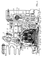
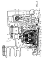
- a power shaft 10 such as the crankshaft of an internal combustion engine, the shaft of a hydraulic motor or the shaft of an electric motor and the rotor 12 of an electric machine 14, such as an integrated starter generator or motor, are driveably connected to and disconnected from two input shafts 16, 18 of a power transmission device, such as a powershift transmission.
- a power transmission device such as a powershift transmission.
- the wheels of a motor vehicle (not shown) are driveably connected alternately to the input shafts 16, 18 through the transmission, which can produce multiple stepped ratios of the speed of its input and output, as described below with reference to Figure 3 .
- the power shaft 10, the rotor 12 and the input shafts 16, 18 all rotate about an axis 19.
- a clutch housing 20 supports input shaft 18 on a bearing 22 and a needle bearing 23 supports input shaft 16 on the inner surface of input shaft 18.
- the input shaft 16 is connected by a spline 24 to a hub 26 of a first clutch output cylinder 27 and input shaft 18 is connected by a spline 28 to the hub 30 of a second clutch output cylinder 31.
- a stator 32 of the electric machine 14 is secured by bolts 36 to the clutch housing 20.
- An adapter housing 38 is secured by bolts 40 to an integral flange 42 of the clutch housing 20.
- a header 33, secured by bolts 35 to clutch housing 20 supports a high voltage connection 39 made when bolts 34 tightly secure the overlying terminals of stator 32 and connector 41 to header 33.
- the rotor 12 is secured to the rotor hub 44 with a pressed ring 15.
- the rotor hub 44 is supported by a bearing 43 on the adapter housing 38.
- the rearward end of rotor hub 44 is connected by bolts 46 to an input cylinder 48, which is secured to a clutch hub 50, such that rotor hub 44, rotor 12, input cylinder 48 and clutch hub 50 all rotate as a unit.
- Needle bearings 52, 54 support the clutch hub 50 on a front support 56, which is secured to clutch housing 20.
- a lip seal 58 located between the adapter housing 38 and rotor hub 44 provides a seal between a wet environment where first and second hydraulically-actuated clutches, 60, 62 are located and the dry environment, where a damper/flywheel assembly 82 and the power shaft 10 are located.
- the dual clutch assembly that includes clutches, 60, 62 transmits torque from power shaft 10 and torque from rotor 12 alternately to the input shafts 16, 18 depending on the engaged and disengaged state of the clutches 60, 62.
- the clutches 60, 62 each include respective pressure balance dam volumes 64, 66 containing hydraulic fluid, which volumes correct for the effect of centrifugal force on the magnitude of hydraulic pressure in the clutch actuation cylinders.
- a front support 56 is formed with four axially spaced and radially directed fluid passages 68, separated by five seals 70.
- the passages 68 which pass through the thickness of the front support 56 and continue through the clutch hub 50, provides lines through which hydraulic apply pressure is communicated to the apply side of the servo piston 72 of clutch 60, to the apply side of the servo piston 74 of clutch 62, and to the balance dams 64, 66.
- the first clutch 60 further includes a first output cylinder driveably connected to the first transmission input shaft 16, a first member driveably connected to the clutch hub 50, first friction discs secured to the first output cylinder, first clutch plates interleaved with the first friction discs and secured to the first member and a first hydraulically-actuated piston 72 for alternately releasing and mutually frictionally engaging the first friction discs and the first clutch plates.
- the second clutch 62 further includes a second output cylinder driveably connected to the second transmission input shaft 18, a second member driveably connected to the clutch hub 50, second friction discs secured to the second output cylinder, second clutch plates interleaved with the second friction discs and secured to the second member and a second hydraulically-actuated piston 74 for alternately releasing and mutually frictionally engaging the second friction discs and the second clutch plates.
- a resolver stator 76 located radially inward on a cylindrical flange of the adapter housing 38 and resolver rotor 78, located radially outward on a cylindrical flange of the rotor hub 44 produce electronic signals representing the rotational speed and angular position of the rotor 12.
- the adapter housing 38 and the lip seal 58 hydraulically and physically separate the dual clutch assembly from a damper/flywheel assembly 82 and the rest of the engine compartment.
- the damper/flywheel assembly 82 is secured at its input side by bolts 84 to the power shaft 10 and is connected at its output side by a spline 90 to rotor hub 44.
- the damper/flywheel assembly 82 contains compression springs 92 arranged mutually in parallel and located in an annular damper recess 94 formed in a damper housing 95.
- the springs 92 are actuated by rotational displacement of the power shaft 10 relative to the rotor hub 44, causing the springs to compress and expand relative to a drive plate 96, which is connected by rivets 86 to a drive hub 88. Expansion and contraction of the springs attenuates torsional displacement and transient vibrations transmitted to rotor hub 44 from power shaft 10. In this way, the damper/flywheel assembly 82 transmits input torque from power shaft 10 to the dual clutch assembly.
- the damper/flywheel assembly 82 is located outside a chamber 98 that is sealed and bounded by lip seal 58, clutch housing 20, the integral flange 42 of the clutch housing 20, and adapter housing 38.
- the location of the damper/flywheel assembly 82 makes efficient use of the space provided, and, although the sealed volume of chamber 98 is located close to the damper/flywheel assembly 82, chamber 98 is hydraulically isolated from it.
- the base transmission which includes the input shafts 16, 18 along with the needle bearing 23 and bearing 22 is assembled into the clutch housing 20.
- header 33 and connector 41 are bolted to clutch housing 20 and the stator 32 is then secured by bolts 36 to the clutch housing 20.
- the high voltage connection 39 is then made by tightly securing the overlying terminals of the stator 32 and connector 41 to the header 33 with bolts 34.
- the front support 56 which includes needle bearings 52, 54 and seals 70 is then inserted and secured to the clutch housing 20.
- an integrated assembly connected by bolts 46 that includes the dual clutch assembly (containing the clutches 60, 62, clutch hub 56, input cylinder 48, and output cylinders 27, 31) and the rotor hub assembly (containing the rotor hub 44, bearing 43, rotor 12, and resolver rotor 78) is inserted over the front support 56, such that clutch cylinder hubs 26 and 30 engage splines 24 and 28, respectively.
- the adapter housing 38 which includes the lip seal 58 and the resolver stator 76 is installed and connected by bolts 40 to the integral flange 42 of the clutch housing 20. Then the damper/flywheel assembly 82 is connected by bolts 84 to the power shaft 10 of the engine.
- the hybrid drive train assembly is completed by installing the engine to the adapter housing 38, such that the drive hub 88 of the damper/flywheel assembly 82 engages the rotor hub 44 at spline 90, and securing the engine to the adapter housing 38 with bolts.
- Figure 3 illustrates details of a powershift transmission 100, which includes the first input clutch 60 for selectively connecting rotor hub 42 alternately to even-numbered gears 146 associated with a first layshaft 144, and the second input clutch 62, which selectively connects rotor hub 42 alternately to odd-numbered gears 147 associated with a second layshaft 149.
- Shaft 144 supports pinions 160, 162, 164, which are each journalled on shaft 144, and couplers 166, 168, which are secured to shaft 144.
- Pinions 160, 162, 164 are associated respectively with the second, fourth and sixth gears.
- Coupler 166 includes a sleeve 170, which can be moved leftward to engage pinion 160 and driveably connect pinion 160 to shaft 144.
- Coupler 168 includes a sleeve 172, which can be moved leftward to engage pinion 162 and driveably connect pinion 162 to shaft 144 and can be moved rightward to engage pinion 164 and driveably connect pinion 164 to shaft 144.
- Shaft 149 supports pinions 174, 176, 178, which are each journalled on shaft 149, and couplers 180, 182, which are secured to shaft 149.
- Pinions 174, 176, 178 are associated respectively with the first, third and fifth gears.
- Coupler 180 includes a sleeve 184, which can be moved leftward to engage pinion 174 and driveably connect pinion 174 to shaft 149.
- Coupler 182 includes a sleeve 186, which can be moved leftward to engage pinion 176 and driveably connect pinion 176 to shaft 149 and can be moved rightward to engage pinion 178 and driveably connect pinion 178 to shaft 149.
- Output 124 supports gears 188, 190, 192, which are each secured to shaft 124.
- Gear 188 meshes with pinions 160 and 174.
- Gear 190 meshes with pinions 162 and 176.
- Gear 192 meshes with pinions 164 and 178.
- Couplers 166, 168, 180 and 182 may be synchronizers, or dog clutches or a combination of these.
- the transmission 100 can produce reverse drive by incorporating a reverse idler gear in one of the lower power paths and a reverse coupler for engaging reverse drive.
- One of the input clutches 60, 62 would be engaged when reverse drive operation is selected.
- an apparatus for transmitting power to a transmission input includes first and second sources of rotary power, first and second transmission input shafts, a clutch hub driveably connected to the first and second power sources, and first and second clutches secured to the clutch hub, for alternately closing and opening a drive connection between the first and second transmission input shafts and the clutch hub.
- the clutches 60, 62 are located axially forward of a rear wall of clutch housing 20, the header 33 provides support and limits excitation of the high voltage connection 39 and is located axially forward of the rear wall of the clutch housing 20 and radially outside the clutches 60, 62.
- the stator 32 and rotor 12 of the electric machine 14 are located axially forward of the header 33 and radially outside the clutches 60, 62.
- the substantially aligned radial position of the header 33 and the electric machine 14 with the clutches 60, 62 reduces the axial length of the apparatus and facilitates cooling of the electric machine 14 and the high voltage connection 39.
- the rotor hub 44 provides support for the rotor 12 of the electric machine 14 and is located axially forward of the clutches 60, 62 and incorporates a resolver rotor 78, which is located axially forward of the rotor hub 44.
- the adapter housing 38 provides support for the rotor hub 44 through a bearing 43 which is located axially forward of the rotor hub 44 and radially inward of the resolver rotor 78.
- the adapter housing 38 is located axially forward of the rotor hub 44 and incorporates a resolver stator 76, which is located axially rearward of the wall of the adapter housing 38.
- the substantially aligned radial position of the bearing 43 with the resolver rotor 78 and the resolver stator 76 reduces the axial length of the apparatus.
- the lip seal 58 prevents leakage of hydraulic fluid from the chamber 98 and is located axially forward of the bearing 43 and radially inward from the wall of the adapter housing 38.
- the damper/flywheel assembly 82 is located axially forward of the wall of the adapter housing 38.
- the arrangement of the elements in the apparatus also facilitates its easy assembly and installation.
- the strategic integration of the dual clutch assembly and rotor hub assembly via a bolted joint interface allows the integrated assembly to be installed where the front support 56 provides radial alignment and support during installation.
- the damper/flywheel assembly 82 is attached to an engine separate from the rest of the apparatus which facilitates the hybrid drive train installation to be similar to a conventional manual transmission or powershift transmission installation to an engine.
- the adapter housing 38 functions as a sealing wall to separate the wet environment of the dual clutch assembly and electric machine 14 from the dry environment of the damper/flywheel assembly 82. This arrangement allows the apparatus to be fully tested prior to final installation with an engine.
- the flange of the adapter housing 38 can be easily modified to accommodate mating various engines, which makes the overall design very portable and does not require significant changes to the base apparatus.
Landscapes
- Engineering & Computer Science (AREA)
- Mechanical Engineering (AREA)
- General Engineering & Computer Science (AREA)
- Chemical & Material Sciences (AREA)
- Combustion & Propulsion (AREA)
- Transportation (AREA)
- Hybrid Electric Vehicles (AREA)
- Arrangement Of Transmissions (AREA)
- Hydraulic Clutches, Magnetic Clutches, Fluid Clutches, And Fluid Joints (AREA)
- Transmission Devices (AREA)
Applications Claiming Priority (1)
| Application Number | Priority Date | Filing Date | Title |
|---|---|---|---|
| US11/823,956 US8863926B2 (en) | 2007-06-29 | 2007-06-29 | Integrated starter generator and input clutch assembly for hybrid electric vehicle |
Publications (4)
| Publication Number | Publication Date |
|---|---|
| EP2011682A2 true EP2011682A2 (de) | 2009-01-07 |
| EP2011682A3 EP2011682A3 (de) | 2011-03-09 |
| EP2011682B1 EP2011682B1 (de) | 2012-03-28 |
| EP2011682B2 EP2011682B2 (de) | 2017-08-30 |
Family
ID=39989666
Family Applications (1)
| Application Number | Title | Priority Date | Filing Date |
|---|---|---|---|
| EP08158475.7A Active EP2011682B2 (de) | 2007-06-29 | 2008-06-18 | Vorrichtung zur Leistungübertragung in ein Getriebe |
Country Status (3)
| Country | Link |
|---|---|
| US (1) | US8863926B2 (de) |
| EP (1) | EP2011682B2 (de) |
| CN (1) | CN101332763B (de) |
Cited By (5)
| Publication number | Priority date | Publication date | Assignee | Title |
|---|---|---|---|---|
| WO2013152939A1 (de) * | 2012-04-12 | 2013-10-17 | Schaeffler Technologies AG & Co. KG | Drehmomentübertragungseinrichtung |
| KR20190033070A (ko) * | 2016-08-05 | 2019-03-28 | 섀플러 테크놀로지스 아게 운트 코. 카게 | 완전 통합식 분리형 및 듀얼 클러치들을 포함한 하이브리드 모듈 |
| WO2019166515A1 (fr) * | 2018-03-02 | 2019-09-06 | Valeo Embrayages | Dispositif de transmission pour vehicule hybride |
| FR3084419A1 (fr) * | 2018-07-30 | 2020-01-31 | Valeo Embrayages | Dispositif de transmission de couple |
| WO2021052687A1 (de) * | 2019-09-16 | 2021-03-25 | Magna Pt B.V. & Co. Kg | Antriebsanordnung für ein kraftfahrzeug |
Families Citing this family (35)
| Publication number | Priority date | Publication date | Assignee | Title |
|---|---|---|---|---|
| FR2871106B1 (fr) * | 2004-06-03 | 2007-10-05 | Peugeot Citroen Automobiles Sa | Element de transmission a double embrayage pour chaine de traction hybride de vehicule automobile, procede de montage, et vehicule automobile equipe d'un tel element |
| JP5413633B2 (ja) * | 2007-10-19 | 2014-02-12 | アイシン・エィ・ダブリュ株式会社 | ハイブリッド駆動装置 |
| DE102010015431A1 (de) * | 2009-05-06 | 2010-11-11 | Luk Lamellen Und Kupplungsbau Beteiligungs Kg | Doppelkupplung mit Drehschwingungsdämpfer |
| WO2010127663A1 (de) * | 2009-05-06 | 2010-11-11 | Schaeffler Technologies Gmbh & Co. Kg | Doppelkupplung mit drehschwingungsdämpfer |
| DE102010018774B4 (de) * | 2009-05-06 | 2020-06-18 | Schaeffler Technologies AG & Co. KG | Doppelkupplung mit Drehschwingungsdämpfer |
| DE102009028514A1 (de) * | 2009-08-13 | 2011-02-17 | Zf Friedrichshafen Ag | Kraftfahrzeuggetriebe |
| JP5149973B2 (ja) * | 2011-02-07 | 2013-02-20 | 株式会社エクセディ | トルク伝達装置 |
| DE102011115286A1 (de) * | 2011-09-29 | 2013-04-04 | Borgwarner Inc. | Parallele Doppelkupplungseinrichtung |
| JP5589247B2 (ja) * | 2011-11-04 | 2014-09-17 | アイシン・エィ・ダブリュ株式会社 | 車両用駆動装置 |
| JP5853761B2 (ja) * | 2012-02-24 | 2016-02-09 | 日産自動車株式会社 | 駆動力伝達装置 |
| JP6028899B2 (ja) * | 2012-04-25 | 2016-11-24 | コベルコ建機株式会社 | ハイブリッド建設機械の駆動装置 |
| WO2014049241A1 (fr) * | 2012-09-25 | 2014-04-03 | Valeo Equipements Electriques Moteur | Module pre-monte pour un ensemble de transmission pour vehicule hybride et procede de montage d'un ensemble de transmission |
| IN2013MU01214A (de) | 2013-03-28 | 2015-06-12 | Tata Motors Ltd | |
| JP6027044B2 (ja) * | 2014-03-14 | 2016-11-16 | トヨタ自動車株式会社 | 車両用駆動装置とその組付方法 |
| KR20160004876A (ko) * | 2014-07-05 | 2016-01-13 | 한승주 | 가변동력전달장치 |
| JP2016033003A (ja) * | 2014-07-29 | 2016-03-10 | アイシン・エィ・ダブリュ株式会社 | ハイブリッド駆動装置 |
| US9866088B1 (en) | 2014-09-26 | 2018-01-09 | Hydro-Gear Limited Partnership | Combination electric generator with electric clutch |
| DE102015209898A1 (de) * | 2015-05-29 | 2016-12-01 | Volkswagen Aktiengesellschaft | Hybrid-Antriebsmodul für ein Kraftfahrzeug |
| DE102015215897A1 (de) * | 2015-08-20 | 2017-02-23 | Schaeffler Technologies AG & Co. KG | Kupplungseinrichtung für Hybridantrieb |
| KR102451874B1 (ko) * | 2016-12-14 | 2022-10-07 | 현대자동차 주식회사 | 하이브리드 전기 자동차용 더블 클러치 장치 |
| KR102417335B1 (ko) * | 2017-04-18 | 2022-07-05 | 현대자동차 주식회사 | 하이브리드 전기 자동차용 더블 클러치 장치 |
| DE102018104363A1 (de) * | 2018-02-27 | 2019-08-29 | Schaeffler Technologies AG & Co. KG | Kupplungsanordnung sowie diese Kupplungsanordnung aufweisende Antriebseinheit |
| DE102019109432A1 (de) * | 2018-06-04 | 2019-12-05 | Schaeffler Technologies AG & Co. KG | Antriebsstrangeinheit für ein Hybridfahrzeug, Getriebeeinheit sowie Antriebsstrang |
| WO2020028511A1 (en) * | 2018-08-02 | 2020-02-06 | Schaeffler Technologies AG & Co. KG | Hybrid module |
| DE102018122386B4 (de) * | 2018-09-13 | 2025-07-10 | Schaeffler Technologies AG & Co. KG | Doppelkupplungseinrichtung für einen Antriebsstrang eines Kraftfahrzeuges mit vollhydraulischer Betätigung |
| DE102019103771A1 (de) * | 2018-11-05 | 2020-05-07 | Schaeffler Technologies AG & Co. KG | Getriebeeinheit und Hybridmodul mit einer getriebeseitigen Trennwand |
| WO2020229528A1 (en) | 2019-05-14 | 2020-11-19 | Transmisiones Y Equipos Mecanicos, S.A. De Cv | 8-speed gearbox |
| DE102019118337A1 (de) * | 2019-05-14 | 2020-11-19 | Schaeffler Technologies AG & Co. KG | Kupplungsvorrichtung, Hybridmodul sowie Antriebsanordnung für ein Kraftfahrzeug |
| WO2020234081A1 (en) * | 2019-05-17 | 2020-11-26 | Transmisiones Y Equipos Mecanicos, S.A. De Cv | Power flow in a double concentric clutch |
| DE102019133283A1 (de) * | 2019-05-27 | 2020-12-03 | Schaeffler Technologies AG & Co. KG | Elektrisches Antriebssystem mit Scheibenläufermotor, Schaltkupplung und Betätigungsvorrichtung |
| JP7545201B2 (ja) * | 2019-10-30 | 2024-09-04 | 株式会社アイシン | 車両用駆動伝達装置、及びそれを備えた車両用駆動装置 |
| KR102292261B1 (ko) * | 2020-02-04 | 2021-08-20 | 주식회사 카펙발레오 | 하이브리드 구동 모듈 |
| KR102292260B1 (ko) | 2020-02-04 | 2021-08-20 | 주식회사 카펙발레오 | 하이브리드 구동 모듈 |
| CN112810425A (zh) * | 2021-02-06 | 2021-05-18 | 哈尔滨东安汽车发动机制造有限公司 | 一种用于混合动力车的传动装置 |
| US20250079935A1 (en) * | 2023-08-30 | 2025-03-06 | Fca Us Llc | Generator assembly and method for attaching generator assembly to an engine |
Family Cites Families (16)
| Publication number | Priority date | Publication date | Assignee | Title |
|---|---|---|---|---|
| JP3777751B2 (ja) | 1997-10-22 | 2006-05-24 | トヨタ自動車株式会社 | エンジンの始動および発電装置 |
| DE19942445A1 (de) | 1998-09-07 | 2000-05-04 | Toyota Motor Co Ltd | Fahrzeugantriebsvorrichtung |
| US6258001B1 (en) | 1999-03-26 | 2001-07-10 | Aisin Aw Co., Ltd. | Vehicle drive train |
| JP3286619B2 (ja) | 1999-04-06 | 2002-05-27 | 株式会社日立製作所 | 自動車の動力伝達装置 |
| WO2001025043A1 (en) | 1999-10-01 | 2001-04-12 | Aisin Aw Co., Ltd. | Hybrid vehicle driving device |
| JP4085558B2 (ja) | 1999-10-01 | 2008-05-14 | アイシン・エィ・ダブリュ株式会社 | ハイブリット車用駆動装置 |
| FR2814516B1 (fr) * | 2000-09-22 | 2003-05-02 | Valeo | Dispositif de transmission a engrenages, en particulier pour vehicule automobile |
| DE50001452D1 (de) * | 2000-10-05 | 2003-04-17 | Ford Global Tech Inc | Doppelkupplung für ein Getriebe mit zwei Getriebeeingangswellen |
| DE10146606A1 (de) † | 2001-09-21 | 2003-04-10 | Zf Sachs Ag | Mehrfach-Kupplungseinrichtung mit axial nebeneinander angeordneten Lamellen-Kupplungsanordnungen |
| US6736228B2 (en) | 2001-11-29 | 2004-05-18 | Visteon Global Technologies, Inc. | Electric machine with integrated wet clutches |
| FR2871205B1 (fr) * | 2004-06-03 | 2007-10-05 | Peugeot Citroen Automobiles Sa | Element de transmission a embrayages humides pour chaine de traction de vehicule automobile, et vehicule automobile equipe d'un tel element |
| US7293637B2 (en) * | 2005-01-06 | 2007-11-13 | Ford Global Technologies, Inc. | Modular twin clutch transmission input for hybrid vehicle |
| DE102005009187A1 (de) * | 2005-03-01 | 2006-09-14 | Zf Friedrichshafen Ag | Torsionsschwingungsdämpfer |
| EP1714817A1 (de) * | 2005-04-19 | 2006-10-25 | Getrag Ford Transmissions GmbH | Hybrid-Doppelkupplungsgetriebe |
| EP1777426B1 (de) † | 2005-10-20 | 2008-10-08 | Getrag Ford Transmissions GmbH | Doppelkupplung |
| DE102005063248B4 (de) * | 2005-12-21 | 2010-09-30 | Getrag Getriebe- Und Zahnradfabrik Hermann Hagenmeyer Gmbh & Cie Kg | Doppelkupplungsanordnung |
-
2007
- 2007-06-29 US US11/823,956 patent/US8863926B2/en active Active
-
2008
- 2008-06-18 EP EP08158475.7A patent/EP2011682B2/de active Active
- 2008-06-26 CN CN200810129377.1A patent/CN101332763B/zh active Active
Cited By (9)
| Publication number | Priority date | Publication date | Assignee | Title |
|---|---|---|---|---|
| WO2013152939A1 (de) * | 2012-04-12 | 2013-10-17 | Schaeffler Technologies AG & Co. KG | Drehmomentübertragungseinrichtung |
| CN104487736A (zh) * | 2012-04-12 | 2015-04-01 | 舍弗勒技术有限两合公司 | 转矩传递装置 |
| CN104487736B (zh) * | 2012-04-12 | 2017-03-22 | 舍弗勒技术股份两合公司 | 转矩传递装置 |
| KR20190033070A (ko) * | 2016-08-05 | 2019-03-28 | 섀플러 테크놀로지스 아게 운트 코. 카게 | 완전 통합식 분리형 및 듀얼 클러치들을 포함한 하이브리드 모듈 |
| WO2019166515A1 (fr) * | 2018-03-02 | 2019-09-06 | Valeo Embrayages | Dispositif de transmission pour vehicule hybride |
| FR3078555A1 (fr) * | 2018-03-02 | 2019-09-06 | Valeo Embrayages | Dispositif de transmission pour vehicule hybride |
| US11358462B2 (en) | 2018-03-02 | 2022-06-14 | Valeo Embrayages | Transmission device for a hybrid vehicle |
| FR3084419A1 (fr) * | 2018-07-30 | 2020-01-31 | Valeo Embrayages | Dispositif de transmission de couple |
| WO2021052687A1 (de) * | 2019-09-16 | 2021-03-25 | Magna Pt B.V. & Co. Kg | Antriebsanordnung für ein kraftfahrzeug |
Also Published As
| Publication number | Publication date |
|---|---|
| CN101332763A (zh) | 2008-12-31 |
| US20090000896A1 (en) | 2009-01-01 |
| CN101332763B (zh) | 2014-09-17 |
| US8863926B2 (en) | 2014-10-21 |
| EP2011682B1 (de) | 2012-03-28 |
| EP2011682B2 (de) | 2017-08-30 |
| EP2011682A3 (de) | 2011-03-09 |
Similar Documents
| Publication | Publication Date | Title |
|---|---|---|
| EP2011682B2 (de) | Vorrichtung zur Leistungübertragung in ein Getriebe | |
| CN103223857B (zh) | 用于混合动力电动车辆的模块化动力总成组件 | |
| US9579965B2 (en) | Modular powertrain component for hybrid electric vehicles | |
| CN103223856B (zh) | 用于混合动力电动车辆的模块化动力总成组件 | |
| US7293637B2 (en) | Modular twin clutch transmission input for hybrid vehicle | |
| CN102308108B (zh) | 用于机动车的传动系的混合组件 | |
| US9157495B2 (en) | Torque converter having integrated flex plate for hybrid electric vehicle | |
| CN102470743B (zh) | 混合动力驱动装置 | |
| US9416826B2 (en) | Disconnect clutch for modular hybrid electric vehicle | |
| US9243669B2 (en) | Torque converter flex plate for hybrid electric vehicle | |
| CN101678752A (zh) | 混合动力驱动装置 | |
| US9243672B2 (en) | Dual drive plate damper for hybrid electric vehicles | |
| JP2013154870A5 (de) | ||
| EP3543556B1 (de) | Dreifachkupplung und stellglied dafür | |
| US9421857B2 (en) | Modular powertrain component for hybrid electric vehicles | |
| CN111163962B (zh) | 离合器装置、混合动力模块和驱动系 | |
| CN113939420A (zh) | 混动离合器模块以及用于具有混动离合器模块的车辆的动力总成 | |
| KR20180068789A (ko) | 변속기용 더블 클러치 장치 | |
| US20140123807A1 (en) | Pneumatic venting of modular hybrid electric vehicle | |
| CN116917152A (zh) | 用于机动车的混合动力变速器和动力总成 |
Legal Events
| Date | Code | Title | Description |
|---|---|---|---|
| PUAI | Public reference made under article 153(3) epc to a published international application that has entered the european phase |
Free format text: ORIGINAL CODE: 0009012 |
|
| AK | Designated contracting states |
Kind code of ref document: A2 Designated state(s): AT BE BG CH CY CZ DE DK EE ES FI FR GB GR HR HU IE IS IT LI LT LU LV MC MT NL NO PL PT RO SE SI SK TR |
|
| AX | Request for extension of the european patent |
Extension state: AL BA MK RS |
|
| PUAL | Search report despatched |
Free format text: ORIGINAL CODE: 0009013 |
|
| RIC1 | Information provided on ipc code assigned before grant |
Ipc: B60K 6/387 20071001AFI20081128BHEP Ipc: F16D 21/06 20060101ALI20110127BHEP Ipc: B60K 6/485 20071001ALI20110127BHEP Ipc: F16D 25/10 20060101ALI20110127BHEP Ipc: F16H 3/00 20060101ALN20110127BHEP |
|
| AK | Designated contracting states |
Kind code of ref document: A3 Designated state(s): AT BE BG CH CY CZ DE DK EE ES FI FR GB GR HR HU IE IS IT LI LT LU LV MC MT NL NO PL PT RO SE SI SK TR |
|
| AX | Request for extension of the european patent |
Extension state: AL BA MK RS |
|
| 17P | Request for examination filed |
Effective date: 20110907 |
|
| GRAP | Despatch of communication of intention to grant a patent |
Free format text: ORIGINAL CODE: EPIDOSNIGR1 |
|
| AKX | Designation fees paid |
Designated state(s): DE GB SE |
|
| RIC1 | Information provided on ipc code assigned before grant |
Ipc: F16H 3/00 20060101ALN20111017BHEP Ipc: B60K 6/405 20071001ALI20111017BHEP Ipc: F16D 21/06 20060101ALI20111017BHEP Ipc: B60K 6/387 20071001AFI20111017BHEP Ipc: B60K 6/485 20071001ALI20111017BHEP Ipc: F16D 25/10 20060101ALI20111017BHEP |
|
| GRAS | Grant fee paid |
Free format text: ORIGINAL CODE: EPIDOSNIGR3 |
|
| GRAA | (expected) grant |
Free format text: ORIGINAL CODE: 0009210 |
|
| AK | Designated contracting states |
Kind code of ref document: B1 Designated state(s): DE GB SE |
|
| REG | Reference to a national code |
Ref country code: GB Ref legal event code: FG4D |
|
| REG | Reference to a national code |
Ref country code: DE Ref legal event code: R096 Ref document number: 602008014389 Country of ref document: DE Effective date: 20120524 |
|
| PG25 | Lapsed in a contracting state [announced via postgrant information from national office to epo] |
Ref country code: SE Free format text: LAPSE BECAUSE OF FAILURE TO SUBMIT A TRANSLATION OF THE DESCRIPTION OR TO PAY THE FEE WITHIN THE PRESCRIBED TIME-LIMIT Effective date: 20120328 |
|
| PLBI | Opposition filed |
Free format text: ORIGINAL CODE: 0009260 |
|
| PLAB | Opposition data, opponent's data or that of the opponent's representative modified |
Free format text: ORIGINAL CODE: 0009299OPPO |
|
| PLAZ | Examination of admissibility of opposition: despatch of communication + time limit |
Free format text: ORIGINAL CODE: EPIDOSNOPE2 |
|
| PLBA | Examination of admissibility of opposition: reply received |
Free format text: ORIGINAL CODE: EPIDOSNOPE4 |
|
| 26 | Opposition filed |
Opponent name: ZF FRIEDRICHSHAFEN AG Effective date: 20121219 |
|
| R26 | Opposition filed (corrected) |
Opponent name: ZF FRIEDRICHSHAFEN AG Effective date: 20121219 |
|
| PLAX | Notice of opposition and request to file observation + time limit sent |
Free format text: ORIGINAL CODE: EPIDOSNOBS2 |
|
| REG | Reference to a national code |
Ref country code: DE Ref legal event code: R026 Ref document number: 602008014389 Country of ref document: DE Effective date: 20121219 |
|
| PLBB | Reply of patent proprietor to notice(s) of opposition received |
Free format text: ORIGINAL CODE: EPIDOSNOBS3 |
|
| PLAB | Opposition data, opponent's data or that of the opponent's representative modified |
Free format text: ORIGINAL CODE: 0009299OPPO |
|
| R26 | Opposition filed (corrected) |
Opponent name: ZF FRIEDRICHSHAFEN AG Effective date: 20121219 |
|
| APAH | Appeal reference modified |
Free format text: ORIGINAL CODE: EPIDOSCREFNO |
|
| APBM | Appeal reference recorded |
Free format text: ORIGINAL CODE: EPIDOSNREFNO |
|
| APBP | Date of receipt of notice of appeal recorded |
Free format text: ORIGINAL CODE: EPIDOSNNOA2O |
|
| APBM | Appeal reference recorded |
Free format text: ORIGINAL CODE: EPIDOSNREFNO |
|
| APBP | Date of receipt of notice of appeal recorded |
Free format text: ORIGINAL CODE: EPIDOSNNOA2O |
|
| APBQ | Date of receipt of statement of grounds of appeal recorded |
Free format text: ORIGINAL CODE: EPIDOSNNOA3O |
|
| APBQ | Date of receipt of statement of grounds of appeal recorded |
Free format text: ORIGINAL CODE: EPIDOSNNOA3O |
|
| APBU | Appeal procedure closed |
Free format text: ORIGINAL CODE: EPIDOSNNOA9O |
|
| PUAH | Patent maintained in amended form |
Free format text: ORIGINAL CODE: 0009272 |
|
| STAA | Information on the status of an ep patent application or granted ep patent |
Free format text: STATUS: PATENT MAINTAINED AS AMENDED |
|
| 27A | Patent maintained in amended form |
Effective date: 20170830 |
|
| AK | Designated contracting states |
Kind code of ref document: B2 Designated state(s): DE GB SE |
|
| REG | Reference to a national code |
Ref country code: DE Ref legal event code: R102 Ref document number: 602008014389 Country of ref document: DE |
|
| PGFP | Annual fee paid to national office [announced via postgrant information from national office to epo] |
Ref country code: GB Payment date: 20190524 Year of fee payment: 12 |
|
| GBPC | Gb: european patent ceased through non-payment of renewal fee |
Effective date: 20200618 |
|
| PG25 | Lapsed in a contracting state [announced via postgrant information from national office to epo] |
Ref country code: GB Free format text: LAPSE BECAUSE OF NON-PAYMENT OF DUE FEES Effective date: 20200618 |
|
| REG | Reference to a national code |
Ref country code: DE Ref legal event code: R084 Ref document number: 602008014389 Country of ref document: DE |
|
| P01 | Opt-out of the competence of the unified patent court (upc) registered |
Effective date: 20230620 |
|
| PGFP | Annual fee paid to national office [announced via postgrant information from national office to epo] |
Ref country code: DE Payment date: 20250509 Year of fee payment: 18 |