EP1800820B1 - Method and apparatus for scribing brittle material board and system for breaking brittle material board - Google Patents
Method and apparatus for scribing brittle material board and system for breaking brittle material board Download PDFInfo
- Publication number
- EP1800820B1 EP1800820B1 EP05790181A EP05790181A EP1800820B1 EP 1800820 B1 EP1800820 B1 EP 1800820B1 EP 05790181 A EP05790181 A EP 05790181A EP 05790181 A EP05790181 A EP 05790181A EP 1800820 B1 EP1800820 B1 EP 1800820B1
- Authority
- EP
- European Patent Office
- Prior art keywords
- scribing
- glass substrate
- mother glass
- securing
- brittle material
- Prior art date
- Legal status (The legal status is an assumption and is not a legal conclusion. Google has not performed a legal analysis and makes no representation as to the accuracy of the status listed.)
- Expired - Lifetime
Links
Images


Classifications
-
- C—CHEMISTRY; METALLURGY
- C03—GLASS; MINERAL OR SLAG WOOL
- C03B—MANUFACTURE, SHAPING, OR SUPPLEMENTARY PROCESSES
- C03B33/00—Severing cooled glass
- C03B33/02—Cutting or splitting sheet glass or ribbons; Apparatus or machines therefor
-
- C—CHEMISTRY; METALLURGY
- C03—GLASS; MINERAL OR SLAG WOOL
- C03B—MANUFACTURE, SHAPING, OR SUPPLEMENTARY PROCESSES
- C03B33/00—Severing cooled glass
- C03B33/10—Glass-cutting tools, e.g. scoring tools
- C03B33/105—Details of cutting or scoring means, e.g. tips
- C03B33/107—Wheel design, e.g. materials, construction, shape
-
- B—PERFORMING OPERATIONS; TRANSPORTING
- B28—WORKING CEMENT, CLAY, OR STONE
- B28D—WORKING STONE OR STONE-LIKE MATERIALS
- B28D5/00—Fine working of gems, jewels, crystals, e.g. of semiconductor material; apparatus or devices therefor
- B28D5/0005—Fine working of gems, jewels, crystals, e.g. of semiconductor material; apparatus or devices therefor by breaking, e.g. dicing
- B28D5/0011—Fine working of gems, jewels, crystals, e.g. of semiconductor material; apparatus or devices therefor by breaking, e.g. dicing with preliminary treatment, e.g. weakening by scoring
-
- C—CHEMISTRY; METALLURGY
- C03—GLASS; MINERAL OR SLAG WOOL
- C03B—MANUFACTURE, SHAPING, OR SUPPLEMENTARY PROCESSES
- C03B33/00—Severing cooled glass
- C03B33/02—Cutting or splitting sheet glass or ribbons; Apparatus or machines therefor
- C03B33/023—Cutting or splitting sheet glass or ribbons; Apparatus or machines therefor the sheet or ribbon being in a horizontal position
- C03B33/03—Glass cutting tables; Apparatus for transporting or handling sheet glass during the cutting or breaking operations
-
- C—CHEMISTRY; METALLURGY
- C03—GLASS; MINERAL OR SLAG WOOL
- C03B—MANUFACTURE, SHAPING, OR SUPPLEMENTARY PROCESSES
- C03B33/00—Severing cooled glass
- C03B33/02—Cutting or splitting sheet glass or ribbons; Apparatus or machines therefor
- C03B33/023—Cutting or splitting sheet glass or ribbons; Apparatus or machines therefor the sheet or ribbon being in a horizontal position
- C03B33/033—Apparatus for opening score lines in glass sheets
-
- C—CHEMISTRY; METALLURGY
- C03—GLASS; MINERAL OR SLAG WOOL
- C03B—MANUFACTURE, SHAPING, OR SUPPLEMENTARY PROCESSES
- C03B33/00—Severing cooled glass
- C03B33/10—Glass-cutting tools, e.g. scoring tools
-
- B—PERFORMING OPERATIONS; TRANSPORTING
- B65—CONVEYING; PACKING; STORING; HANDLING THIN OR FILAMENTARY MATERIAL
- B65G—TRANSPORT OR STORAGE DEVICES, e.g. CONVEYORS FOR LOADING OR TIPPING, SHOP CONVEYOR SYSTEMS OR PNEUMATIC TUBE CONVEYORS
- B65G2249/00—Aspects relating to conveying systems for the manufacture of fragile sheets
- B65G2249/04—Arrangements of vacuum systems or suction cups
-
- Y—GENERAL TAGGING OF NEW TECHNOLOGICAL DEVELOPMENTS; GENERAL TAGGING OF CROSS-SECTIONAL TECHNOLOGIES SPANNING OVER SEVERAL SECTIONS OF THE IPC; TECHNICAL SUBJECTS COVERED BY FORMER USPC CROSS-REFERENCE ART COLLECTIONS [XRACs] AND DIGESTS
- Y02—TECHNOLOGIES OR APPLICATIONS FOR MITIGATION OR ADAPTATION AGAINST CLIMATE CHANGE
- Y02P—CLIMATE CHANGE MITIGATION TECHNOLOGIES IN THE PRODUCTION OR PROCESSING OF GOODS
- Y02P40/00—Technologies relating to the processing of minerals
- Y02P40/50—Glass production, e.g. reusing waste heat during processing or shaping
- Y02P40/57—Improving the yield, e-g- reduction of reject rates
Definitions
- the present invention relates to: a scribing method for scribing brittle material substrates such as semiconductor wafers, glass substrates, and ceramic substrates along a planned scribing line; a scribing apparatus utilizing the method thereof; and a separating system for brittle material substrates.
- Display devices with flat display panels such as liquid crystal display panels, plasma display panels, and organic electroluminescence display panels, structure panel substrates by bonding two sheets of glass substrate that are brittle material substrates.
- a mother glass substrate is separated into glass substrates with predetermined sizes.
- the separating process of the glass substrate involves forming a scribe line on the mother glass substrate along a planned scribing line. Following this, the mother glass substrate is then separated along the scribe line by using the formed scribe line as a central axis to apply a predetermined amount of internal bending stress to the substrate.
- Panel substrates employed by flat panel displays that are display devices are fabricated by separating a mother glass substrate with large dimensions into glass substrates of predetermined sizes.
- mother glass substrates have also become larger; some, for example, to dimensions of 1100 mm ⁇ 1250 mm.
- mother glass substrates that are 0.5 mm in thickness are starting to be used.
- mother glass substrates that have large dimensions of 1500 mm ⁇ 1800 mm but are only 0.7 mm in thickness are also being used.
- a mother glass substrate is to be fixed on a securing table and thereafter, the substrate is pressed and rolled over by a wheel cutter for scribing, or a crack is made in advance on the mother glass substrate and thereafter, a laser beam shall irradiate the tip of the crack to generate thermal distortion, while at the same time the crack is propagated further by means of shifting the position of the laser beam irradiation.
- a scribe line will generate from a vertical crack formed along the direction of the thickness of the mother glass substrate.
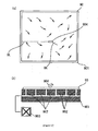
- Figure 12(a) is a pattern diagram describing problems that result when scribing the mother glass substrate while utilizing conventional scribing methods.
- Figure 12(b) is a sectional side view of Figure 12(a) .
- a suction means 903 such as a vacuum pump or a suction motor and the mother glass substrate 90 is vacuum-chucked to securing table 901 by means of the suction holes suctioning the mother glass substrate 90 when it is placed on the upper surface of the securing table 901.
- the cutter wheel 904 If the cutter wheel 904 is pressed and rolled on the surface of the mother glass substrate 90 to scribe along the planned scribing line when unequal internal stress is produced in the mother glass substrate 90 as describe above, the cutter wheel may be subjected to influence by the internal stress within the mother glass substrate 90. If this happens, there is concern that an unnecessary crack UC may continuously derive in an unspecified and uncontrollable direction on a vertical crack produced during scribing (described as scribe line SL on the Figure). Such a phenomenon is considered to result from a loosening in internal stress within the mother glass substrate 90 due to the vertical crack being formed, as well as distortions that are produced in the scribing direction (front side) on the mother glass substrate 90.
- the mother glass substrate cannot be separated into glass substrates of predetermined sizes during the separating (breaking) process later on. Because of this, there is concern that the yield rate regarding the fabrication of panel substrates for flat panel displays could significantly decrease, as the bigger the dimensions of the mother glass substrate becomes, the more prominent the adverse effects caused by fluctuations in the foregoing internal stress will notably appear.
- each mother glass substrate will have produced large localized distortions within. Securing on a securing table and scribing a mother glass substrate in which such large distortions have resulted thereon, will increase the degree of abovementioned unnecessary cracks generating in an unspecified and uncontrollable direction during scribing. This in turn raises the chances of a defective separated product being fabricated from the mother glass substrate.
- TFT thin film transistor
- US 2004/0074366 A1 discloses scribing apparatuses for cutting liquid crystal display panels.
- the scribing apparatus shown in Fig. 8 has a pair of securing tables arranged with an interval and means for table movement. Suction holes disposed on the surfaces of the first and second tables are used to hold first and second brittle material substrates in cutting them along first and second scribe lines formed at the surfaces of the first and second substrates with respective cutting wheels. Then, after forming the first and second scribe lines, the first and second tables are moved to different directions to break or cut the substrates along the scribe lines.
- JP 11-079770 A when a scribe line is formed on a glass substrate by means of a cutter, the section of the glass substrate on which the scribe line is to be formed is pressed and protruded upwards. This is in order to add tension to the glass substrate along a direction perpendicular to the traveling direction of the cutter. Disclosed thereinafter is a structure for scribing under these pressed conditions.
- the present invention is designed to solve these problems, and the purpose of the invention is to provide a scribing method, a scribing apparatus, and a separating system that will precisely form a scribe line along a planned scribing line on a brittle material substrate such as glass substrates. Thereby, the present invention will significantly increase yield rates of the separating procedure for brittle material substrates.
- a scribing method will be provided for when forming a scribe line along a planned scribing line arranged on at least one side of a brittle material substrate, wherein internal stress in the vicinity of the planned scribing line is equalized by forming a micro distortion in advance on the said brittle material substrate.
- the scribing method according to the present invention is defined in claim 1.
- a scribing apparatus for forming a scribe line along a planned scribing line arranged on at least one side of a brittle material substrate, wherein the scribing apparatus has means for equalizing internal stress so that internal stress in the vicinity of the planned scribing line will be equalized.
- This will be by means of a scribing method for forming a vertical crack through the thickness of the said brittle material substrates, and by forming a micro distortion on the said brittle material substrate.
- the scribing apparatus according to the present invention is defined in claim 3.
- a separating system for a brittle material substrate, wherein possessing a breaking device for breaking the said brittle material substrate along a scribe line formed on the said brittle material substrate by means of the said scribing apparatus.
- the separating system according to the present invention is defined in claim 5.
- the internal stress in the vicinity of the planned scribing line can be equalized.
- an unnecessary crack can be prevented from deriving on a vertical crack formed on the brittle material substrate.
- the internal stress potentially secured by the said brittle substrate can be distributing towards a pulling direction or a compressing direction.
- the micro distortion formed in advance on the said brittle material substrate will off set differences between the maximum value and the minimum value of such internal stress distribution along the planned scribing line. As a result, a vertical crack can be precisely formed along the planned scribing line in which internal stress has been equalized.
- micro distortion is formed on the said substrate by having each of the said securing tables mutually approach or draw from each other in the direction perpendicular to the said planned scribing line (or in a direction along the said planned scribing line). Therefore, it is possible to achieve an equalized internal stress through simple mechanisms.
- the equalizing of stresses near the planned scribing line is detected by an internal stress detecting means.
- a method for forming a scribe line includes a method whereby a laser beam is irradiated along the said planned scribing line and/or a method wherein a wheel cutter is rolled along the planned scribing line.
- the method that irradiates a laser beam uses thermal disposition generated on the brittle material substrate to produce a vertical crack and form a scribe line. Because of this, when a region with equalized internal stress is scribed, there is no residual internal stress distortions on the edges of the separated surface of the brittle material substrate after being separated, thus preventing unnecessary chipping from generating on the separated surface.
- the range of conditions for forming a scribe line on the brittle material substrate becomes expanded, thus scribe lines can be formed along a planned scribing line on a stable basis.
- the scribing apparatus for brittle material substrate of the present invention by forming a micro distortion in advance on the brittle material substrate, the internal stress in the vicinity of the planned scribing line is equalized. Thus, unnecessary cracks are prevented from deriving from a vertical crack formed on the brittle material substrate.
- the configuration further has internal stress detection means that detect the equalizing of internal stress near the planned scribing line.
- the configuration further has a control unit for carrying out instructions to the said means of table movement to have each of the said securing tables approach or draw from each other according to detection results detected by internal stress detection means.
- the separating system for a brittle material substrate is made by integrally connecting the scribing apparatus of the present invention and the breaking device that breaks the said substrate along the scribe line formed on the brittle material substrate by means of the said scribing apparatus.
- the system can continuously carry out the processes of forming a scribe line and breaking the said substrate along the formed scribe line, over a device with a single line constitution.
- the present invention can positively form a scribe line along the planned scribing line on a brittle material substrate such as glass substrate, the yielding rate of work separating the brittle material substrate can be significantly improved.
- equalizing of internal stress near the planned scribing line is carried out by either compressing or pulling the brittle material substrate in advance towards a direction coinciding with the scribing direction.
- FIG 1 is a perspective view showing a schematic structure of the scribing apparatus.
- the scribing apparatus 10 is an apparatus that forms a scribe line on the mother glass substrate 90.
- scribing apparatus 10 consists of a slidable table 12 that is reciprocally movable along base 11 in a horizontal direction (along the Y axial direction in the Figure).
- the slidable table 12 is supported to be slidable along a pair of horizontal guide rails 14 and 15.
- the guide rails 14 and 15 are parallel to each other and are provided on the upper surface of the base 11 while they extend in the Y axial direction.
- a ball screw 13 parallel to the guide rails 14 and 15 is set up so as to be rotated by a motor 16.
- a ball nut (not shown) is engaged with the ball screw 13, and by means of the ball screw 13 rotating forward and backward, the ball nut slides along the ball screw 13 in both directions.
- a rotating mechanism 17 is provided on the slidable table 12.
- a subtable 18 is attached on top of the rotating mechanism 17 in a state horizontal to the rotating mechanism 17.
- the rotating mechanism 17 rotates the subtable 18 around a central axis going in a vertical direction so the table will be at an arbitrary rotation angle ⁇ against the standard position.
- the subtable 18 consists a pair of tables, the first securing table 21 and the second securing table 22. Each is reciprocally movable in a horizontal state along a direction perpendicular to the Y axial direction (X axial direction).
- the first securing table 21 and the second securing table 22 are slidable along a pair of horizontal guide rails 19 and 20.
- the guide rails 19 and 20 are provided over the upper surface of the subtable 18 and extend in the X axial direction, parallel to each other.
- the first securing table 21 and the second securing table 22 are provided along the X axial direction with predetermined spacing according to the size of the mother glass substrate 90.
- On the upper surface of the first securing table 21 and the second securing table 22 a plurality of suction holes not shown on the Figure are provided. The suction holes are connected to a vacuum pump, and will suction-chuck the mother glass substrate 90.
- a guide beam 25 is spanned between the top edges of a pair of pillars 26 on the upper side of the first securing table 21 and the second securing table 22.
- the guide beam 25 extends along the X axial direction perpendicular to the sliding direction of the subtable 18 (Y axial direction).
- a guide rail 27 is set up; and on this guide rail 27, a scribing unit 28 is set up to be slidable thereon.
- the scribing unit 28 will be slid towards the X axial direction by, for example, drive mechanisms such as a motor 33 and a ball screw (not shown).
- a scribe head 29 is attached on the scribing unit 28, and a vertically movable tip holder 32 that supports the cutter wheel tip 31 so it is rotatable is provided on the scribe head 29.
- a pair of CCD (Charge Coupled Device) cameras 34a and 34b are set up on a support 35.
- the cameras are to image the alignment mark provided on the mother glass substrate 90.
- Oscillatory tables 36a and 36b correspondingly adjust the positions of CCD cameras 34a and 34b in the Y axial direction.
- the cameras can be moved individually in the X axial direction, which is driven by motor and ball screw or linear motor driving mechanisms.
- the positions of the first securing table 21 and the second securing table 22 in the X axial direction are arranged in accordance with the size of the mother glass substrate 90.
- the spacing between the first securing table 21 and the second securing table 22 is adjusted.
- the mother glass substrate 90 is then mounted on top of the first securing table 21 and the second securing table 22.
- the vacuum pump (not shown) is then driven, and the mother glass substrate 90 is suctioned by suction holes provided on the surface of the first securing table 21 and the second securing table 22 and suction-chucked to the first securing table 21 and the second securing table 22.
- the line connecting the image centers of CCD camera 34a and CCD camera 34b is adjusted to be parallel to the planned scribing line. This is done by correspondingly utilizing the oscillatory tables 36a and 36b to adjust the position of CCD camera 34a and CCD camera 34b in the Y axial direction. After this, the CCD camera 34a and the CCD camera 34b are individually moved in the X axial direction, while the slidable table 12 is moved in the Y axial direction and subtable 18 is rotated.
- the central position between the pair of alignment marks provided on the mother glass substrate 90 are coincided with the image center of CCD camera 34a and CCD camera 34b.(hereafter, this position of the subtable 18 and the pair of CCD cameras 34a and 34b will be referred to as the alignment position).
- the planned scribing line of the mother glass substrate 90 becomes parallel to the X axial direction to which the scribe line is actually formed.
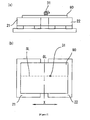
- Figure 2(a) is a schematic front view of the first securing table 21 and the second securing table 22, and Figure 2(b) is a top view of Figure 2(a) .
- the first securing table 21 is slid a micro distance (for example, 100 ⁇ m) along the X axial direction so as to approach the second securing table 22.
- the internal stress (not shown) is equalized along the planned scribing line towards the section of the mother glass substrate 90 that is between the first securing table 21 and the second securing table 22.
- the second securing table 22 alone may be slid a micro distance along the X axial direction towards a static first securing table 21.
- both the first securing table 21 and the second table 22 may be slid a micro distance along the X axial direction so they mutually approach one another.
- the cutter wheel 31 of the scribe head 29 is positioned on the scribe line formation start position on the planned scribing line. After sliding the scribing unit 28 in the scribing direction (X axial direction), the cutter wheel tip 31 is pressed and rolled along the planned scribing line on the mother glass substrate 90. By this, a scribe line is formed along the planned scribing line (predetermined separation line).
- the internal stress of the mother glass substrate 90 to which the cutter wheel 31 is rolled on is equalized along the borderline BL between the first securing table 21 and the second securing table 22.
- the mother glass substrate 90 is setup on the surface of the first securing table 21 and the second securing table 22, suctioned by vacuum pumps and that alike from suction holes setup on the surfaces of the first securing table 21 and the second securing table 22, and suction-chucked to the first securing table 21 and the second securing table 22 through these means, the uneven internal stresses within the substrate can be equalized by the first securing table 21 and/or the second securing table 22 moving a micro distance along the X axial direction as mentioned above.
- the micro distance to be traveled along the X axial direction by the first securing table 21 and/or the second securing table 22 will be arranged in advance when arranging scribing conditions such as: choice for a scribing cutter, edge load given to the scribing cutter for pressing the mother glass substrate 90, and scribing speed.
- the direction of the internal stress that is generated in the mother glass substrate 90 will precisely coincide that of the scribing direction taken by the cutter wheel 31.
- conditions are arranged so an unnecessary crack will not derive in front of the vertical crack formed on the mother glass substrate 90 by cutter wheel 31.
- a vertical crack can be precisely formed along the planned scribing line.
- the example has described scribing to be done by forming an internal stress compressing the mother glass substrate 90 along the scribing direction (X axial direction) by means of the two tables 21 and 22 mutually approaching each other.
- the first securing table 21 and/or the second securing table 22 may travel a micro distance along the X axial direction while mutually drawing apart from each other to form a tensile internal stress in the mother glass substrate 90.
- the size of the internal stress generated in the mother glass substrate is a degree that will cause a slight, but not altering, distortion on the principle surface of the mother glass substrate 90. This is to prevent the mother glass substrate 90 from being separated at approximately the same time as the scribing. If the mother glass substrate is separated at approximately the same time as the scribing, there is concern that the separated glass substrate will become defective if the separated surface is affected by the internal stress in the mother substrate 90 and becomes an inclined surface.
- the mother glass substrate 90 is suction-chucked to the first securing table 21 and the second securing table 22 by suction holes set up on surfaces of the first securing table 21 and the second securing table 22 that suction the mother glass substrate 90 with vacuum pumps and alike.
- suction holes set up on surfaces of the first securing table 21 and the second securing table 22 that suction the mother glass substrate 90 with vacuum pumps and alike.
- Embodiment 1 represents an example of a scribing apparatus, wherein equalizing of internal stress near the planned scribing line is carried out by either compressing or pulling a brittle material substrate in advance towards a direction perpendicular to the scribing direction.
- Embodiment 1 will represent an example of a scribing apparatus consisting of an internal stress detection means.
- FIG 3 is a schematic structural perspective view showing the scribing apparatus.
- This scribing apparatus 40 does not have any structural differences from the scribing apparatus of the example shown in Figure 1 , aside from the structure of the first securing table and the second securing table, and that a distortion detection unit 47 for detecting distortions on the surface of mother glass substrate 90 will travel along guide bar 25. For this reason, detailed explanations of the parts that are unchanged will be omitted by utilizing the same numerical codes for the same components.
- the subtable 18 consists a pair of tables, the first securing table 41 and the second securing table 42, which are reciprocally movable in a horizontal state along the Y axial direction.
- the first securing table 41 and the second securing table 42 are supported by a pair of guide rails 43 and 44, which are provided over the upper surface of the subtable 18 and extend in the Y axial direction while remaining parallel to each other.
- the supported securing tables become horizontally slidable along each of the guide rails 43 and 44, and are slid by drive mechanisms 45 and 46 such as a ball screw/motor or a linear motor. All other structures are in common with the example shown in Figure 1 , and thus explanations are omitted.
- a distortion detection unit 47 is set up on the guide rail 27 and is slidable in the X axial direction.
- the distortion detection unit 47 can be moved in the X axial direction by, for example, drive mechanisms such as motor 48 and a ball screw (not shown).
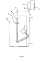
- Figure 4 is a schematic structural view showing the structure of the distortion detection unit 47.
- a laser light emitted from a diode laser 51 provided on base 11 is narrowed by a convex lens 52, and input into distortion detection unit 47 by bending mirror 53 and bending mirror 54.
- the laser light forms a plurality of laser light groups lined in a single parallel row by passing through the first etalon 55.
- This row made of a plurality of laser lights then passes through the second etalon 56 to form a batch of laser light groups lined in several rows.
- This single batch of laser light groups then irradiates to, and reflects off, the surface of the mother glass substrate 90 and is then detected by CCD camera 57.
- the strength signals of these are then processed by an image processor (not shown), analyzed by an arithmetic processing unit (not shown), and microscopic displacements that had generated on the mother glass substrate 90 are detected.
- first securing table 41 and the second securing table 42 are arranged in a position accordingly adapted to the size of the mother glass substrate 90 in the Y axial direction. At the same time, spacing between the first securing table 41 and the second securing table 42 is adjusted.
- the mother glass substrate 90 is provided on top of the first securing table 41 and the second securing table 42.
- the vacuum pump (not shown) will then be driven so that the mother glass substrate 90 is suctioned by the suction holes setup on the surface of the securing table 41 and the second securing table 42, and becomes adsorbed and fixed to the first securing table 41 and the second securing table 42.
- the positions of the CCD camera 34a and CCD camera 34b on the Y axial direction are adjusted by correspondingly utilizing the oscillatory tables 36a and 36b.
- the CCD camera 34a and the CCD camera 34b are individually moved in the X axial direction, the slidable table 12 is moved in the Y axial direction, and the subtable 18 is rotated.
- the central position of the pair of alignment marks provided on the mother glass substrate 90 in the image center of CCD camera 34a and CCD camera 35b coincide.
- the planned scribing line of the mother glass substrate 90 becomes parallel to the X axial direction to which the scribe line is actually formed.
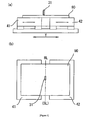
- Figure 5(a) is a front view of the first securing table 21 and the second securing table 22, and Figure 5(b) is a top view of Figure 5(a) .
- the first securing table 41 for example, is slid for a micro distance (for example, 100 ⁇ m) along the Y axial direction to approach the second securing table 42.
- the internal stress (not shown) is equalized along the planned scribing line SL towards the section of the mother glass substrate 90 between the first securing table 41 and the second securing table 42.
- the strength of the internal stress along the Y axial direction is equalized along the planned scribing line SL on the mother glass substrate 90 by adjusting the distance interval between the first securing table 41 and the second securing table 42.
- the cutter wheel 31 in the scribe head 29 is positioned on the scribe line formation start position on the planned scribing line.
- a scribing unit 28 is then slid in the scribing direction (X axial direction), and the cutter wheel 31 is pressed and rolled along the planned scribing line on the mother glass substrate 90. By doing this, a scribe line is formed along the planned scribing line SL (planned separation line).
- the micro distance to be traveled by the first securing table 41 and/or the second securing table 42 along the Y axial direction is accordingly arranged in advance when arranging scribing conditions such as: the scribing cutter to be used, the edge load given to the scribing cutter for pressing the mother glass substrate 90, and the scribing speed.
- the size of the internal stress generated in the mother glass substrate 90 is a degree that will cause a slight, but not altering, distortion on the principle surface of the mother glass substrate 90. This is to prevent the mother glass substrate 90 from being separated at approximately the same time as the scribing. If the mother glass substrate is separated at approximately the same time as the scribing, there is concern that the separated glass substrate will become defective if the separated surface is affected by the internal stress in the mother substrate 90 and becomes an inclined surface.
- Embodiment 1 of the present invention by means of the first securing table 41 and/or the second securing table 42 traveling a micro distance along the Y axial direction, border line BL in the direction of the internal stress generating within the mother glass substrate 90 will coincide with the planned scribing line.
- the abovementioned micro distance is arranged to prevent an unnecessary crack from forerunning when scribing, there is little concern that an unnecessary crack that is out of alignment with the planned scribing line SL will continuously derive from the vertical crack formed by the cutter wheel 31 on the mother glass substrate 90.
- a vertical crack can be formed with certainty along the planned scribing line SL.
- Embodiment 1 of the present invention has described scribing to be done by forming an internal stress compressing the mother glass substrate 90 along the scribing direction (X axial direction) by means of two tables 41 and 42 mutually approaching each other.
- the first securing table 41 and/or the second securing table 42 may travel a micro distance along the Y axial direction in a manner mutually drawing apart from each other to form a tensile internal stress in the mother glass substrate 90.
- Embodiment 2 represents an example of a scribing apparatus that carries out an equalizing of internal stress near the planned scribing line by either compressing or pulling in advance the brittle material substrate at a 45° angle horizontally inclined to the scribing direction.
- FIG 6 is a schematic structural perspective view showing another Embodiment of the scribing apparatus of the present invention.
- This scribing apparatus 60 does not have any structural differences from the scribing apparatus of Embodiment 1 shown in Figure 3 , aside from the structures of the first securing table and the second securing table, and also that the direction of travel by the first securing table and the second securing table is arranged to be at a 45° inclined angle to the X axial direction perpendicular to the sliding direction of the slidable table 12. For this reason, detailed explanations of the parts that are unchanged will be omitted by utilizing the same numerical codes for the same components.
- the direction of travel by the first securing table 61 and the second securing table 62 is arranged to be at a 45° inclined angle to the X axial direction perpendicular to the sliding direction of the slidable table 21.
- an internal stress will be generated along a direction at a angle 45° inclined to the X axial direction throughout the entire mother glass substrate 90 to which the cutter wheel 31 is to be pressed and rolled on.
- the internal stress sandwiches the borderline BL between the first securing table 61 and the second securing table 62 and mutually faces reverse directions.
- the mother glass substrate 90 is set up on the surface of the first securing table 61 and the second securing table 62 and suction-chucked to the first securing table 61 and the second securing table 62 by suctioning via vacuum pumps and that alike from suction holes setup on the surfaces of the first securing table 61 and the second securing table 62, internal stress is generated within the mother glass substrate 90.
- This in turn is equalized in a direction at an angle 45° inclined to the X axial direction by moving the first securing table 61 and/or the second securing table 62 for a micro distance along a 45° angle inclined to the X axial direction as mentioned above.
- the micro distance traveled by the first securing table 61 and/or the second securing table 62 along a direction at a 45° inclined angle to the X axial direction is arranged in advance when arranging scribing conditions such as: the selection of a scribing cutter, the edge load given to the scribing cutter for pressing the mother glass substrate 90, and the scribing speed. This is to prevent unnecessary cracks from continuously deriving on a vertical crack formed during the scribing process.
- a vertical crack can be precisely formed along the planned scribing line SL.
- the size of the internal stress generated in the mother glass substrate 90 is a degree that will cause a slight, but not altering, distortion on the principle surface of the mother glass substrate 90. This is to prevent the mother glass substrate 90 from being separated at approximately the same time as the scribing. If the mother glass substrate is separated at approximately the same time as the scribing, there is concern that the separated glass substrate will become defective if the separated surface is affected by the internal stress in the mother substrate 90 and becomes an inclined surface
- Embodiment 2 of the present invention describes scribing to be done by forming an internal stress compressing the mother glass substrate 90 along a direction at a 45° inclined angle to the scribing direction (X axial direction).
- the first securing table 61 and/or the second securing table 62 may travel a micro distance along a parallel direction and at a 45° inclined angle to the X axial direction to mutually draw apart from each other and form a tensile internal stress in the mother glass substrate 90.
- the angle of the direction that the first securing table 61 and the second securing table 62 travels is not limited to a 45° inclined angle when inclining in a horizontal direction to the scribing direction (X axial direction), and can be arranged at various angles coinciding to the scribing condition of the mother glass substrate.
- the mother glass substrate 90 is set up on and suction-chucked to the first securing table 61 and the second securing table 62 by suction holes setup on surfaces of the first securing table 61 and the second securing table 62 that suction the mother glass substrate 90 with vacuum pumps and alike.
- first securing table 61 and/or the second securing table 62 as above mentioned for a micro distance along a direction that is parallel to and inclined in a predetermined angle to the scribing direction (X axial direction), and organized towards a direction that is parallel and inclined in a predetermined angle to the scribing direction (X axial direction).
- Embodiment 2 of the present invention equalizes ununiform internal stress immanent in the mother glass substrate 90. Scribing is then conduct on the mother glass substrate 90 in this state.
- Embodiment 3 represents an example of a separation device for brittle material substrates that combines a breaking mechanism to a scribing apparatus.
- Figure 7 is a perspective view showing a schematic structure of a separation system 100 for brittle material substrates. The system forms scribe lines on a brittle material substrate by utilizing the scribing method of the present invention, while subsequently comprising a breaking mechanism for breaking the brittle material substrate.
- the separating device is employed when, for example, separating a mother glass substrate 90 that is a brittle material substrate into predetermined sizes to be used for a liquid crystal display panel.
- the mother glass substrate 90 to be separated is horizontally mounted on a pair of substrate-supporting mechanisms 120, set up on base 118.
- a scribing unit 130 and a breaking unit 140 are set up between the two substrate-supporting mechanisms 120. These units will scribe and separate the mother glass substrate 90 while it is supported in a spanned state by the two substrate-supporting mechanisms 120.
- Each of the substrate-supporting mechanisms 120 correspondingly consist a first securing table 121a and a second securing table 121b for mounting the mother glass substrate 90.
- the first securing table 121a and the second securing table 121b are slidable in the substrate transporting direction (Y axial direction indicated in Figure 7 ) as each is supported by a pair of supports 123 that are horizontally set up on base 118.
- the first securing table 121a and the second securing table 121b each slide against the pair of supports 123 along the Y axial direction by means of slide driving mechanisms that are not shown in the Figure, such as a linear motor.
- the first securing table 121a and the second securing table 121b rotatably set up a plurality of transportation rollers 122 therein.
- the rollers transport the mounted mother glass substrate 90 along the Y axial direction.
- the axial directions of each of the corresponding transportation rollers 122 are along the X axial direction in a perpendicular state to the sliding direction (Y axial direction) of the first securing table 121a and the second securing table 121b.
- the rollers form a plurality of lines along the Y axial direction (in the case of Figure 7 , two lines are formed), and in each line, the corresponding transportation rollers 122 are provided with fixed spacing in-between adjacent transportation rollers 122.
- Each transportation roller 122 also possesses a vertical movement device not shown in the figure that conducts vertical movement using means of driving mechanisms correspondingly utilizing air cylinders and motors.
- the upper section of each of the transportation rollers 122 can be from a state wherein protruding above the upper surface of the first securing table 121a and the second securing table 121b to a state wherein not protruding above the upper surface of the first securing table 121a and the second securing table 121b.
- first securing table 121a and the second securing table 121b each have a plurality of suction holes 124 that are correspondingly set up to suction and adsorb the mother glass substrate 90 mounted thereon.
- Figure 8(a) is a schematic structural view of the adsorption mechanism set up on the first securing table 121a and the second securing table 121b.
- Figure 8(b) is a plan view of Figure 8(a) .
- this adsorption mechanism consists of a plurality of suction holes 124 with openings on the upper surface of the first securing table 121a and the second securing table 121b.
- the mechanism also consists of suction means 125, such as a vacuum pump or a suction motor, which create a state of negative pressure within the suction holes 124.
- the scribing unit 130 and the breaking unit 140 are attached to and slidable along the upper guide rail 112 and lower guide rail 113.
- the units are slidable by means of, for example, a linear motor mechanism.
- the guide rails are provided along the X axial direction, perpendicular to the direction the mother glass substrate 90 is transported by the substrate supporting mechanism 120.
- Each of the ends of upper guide rail 112 horizontally span between the upper sections of the pair of pillars 111 that are vertically set up on base 118.
- Each of the ends of lower guide rail 113 horizontally span between the lower sections of the pair of pillars 111.
- Each of the pillars 111 are slidable along the Y axial direction against the upper surface of base 118 by means of slider 114.
- the Y axial direction is perpendicular to the direction of the upper guide rail 112 and lower guide rail 113.
- Each of the pillars 111 are integrally structured with the upper guide rail 112 and lower guide rail 113. Thus by each of the pillars 111 sliding with support from slider 114, the upper guide rail 112 and lower guide rail 113 will become integral and also slide along the Y axial direction.
- the lower guide rail 113 is provided between the lower sections of each of the pillars 111.
- a drive unit for linear interpolation is set up on the lower section of the longitudinal central section of the lower guide rail 113.
- the drive unit for linear interpolation possesses a ball screw 115 along the Y axial direction perpendicular to the lower guide rail 113.
- the ball screw 115 is able to rotate in either direction of rotation by motor 116.
- Ball screw 115 is engaged by a ball nut (not shown) attached on the longitudinal central section of the lower guide rail 113.
- momentum going along the transportation direction of the mother glass substrate 90 is applied to the lower guide rail 113.
- each of the pillars 111 that are slidably supported by the slider 114 will slide in a direction perpendicular to the upper guide rail 112 and the lower guide rail 113.
- a pair of positioning cameras 117 are set up in the longitudinal direction of the upper guide rail 112 with spacing that is adapted to the size of the mother glass substrate 90.
- the positioning cameras image alignment marks, set up on the mother glass substrate 90 to calculate tilting regarding the upper guide rail 112 and the lower guide rail 113 against the mother glass substrate 90.
- FIG 9 is a front view showing the structures of the scribing unit 130 and the breaking unit 140.
- the scribing unit 130 is described. As shown in Figure 7 , each mechanism of the scribing unit 130 described hereafter travels along the lower guide rail 113 in an integrate fashion with the scribing unit 130.
- the scribing unit 130 is set up below the mother glass substrate 90 to be transported.
- the scribing unit 130 is made of a unit body 131 slidably attached to the lower guide rail 113; and virtually in the central section of this unit body 131, a cooling mechanism 132 for spraying cooling water upward.
- a laser beam irradiation optical system 133 for irradiating laser beams upward.
- the laser beam irradiation optical system 133 irradiates laser beams to the mother glass substrate 90 fixed in a spanned state by means of a pair of substrate supporting mechanisms 120.
- the cooling mechanism 132 sprays cooling water on the area near to the section of the mother glass substrate 90 to which the laser irradiates.
- a cutting mechanism 134 for an incision is set up.
- the mechanism forms a vertical crack (incision) on the scribing starting location of the mother glass substrate 90 to act as a trigger for the scribing procedure.
- the cutting mechanism for an incision 134 possesses a blade section 134a provided along the sliding direction of the scribing unit 130. This blade section 134a is attached on the upper end of bracket 134b with the edge of the blade facing upward. Bracket 134b is to be vertically moved by means of an air cylinder for vertical movement 134c set up on the unit body 131.
- Cooling mechanism 132 possesses a nozzle 132a that sprays cooling water upwards. By means of air cylinder 132b this nozzle 132a is able to vertically move between a spraying position near the mother glass substrate 90 on which the nozzle 132a sprays cooling water onto, and a stand-by position below and separate from the mother glass substrate 90.
- a substrate securing roller mechanism 135 is set up. Between the substrate securing roller mechanism 135 and the cooling mechanism 132, the first auxiliary roller mechanism 136 is set up; and against the substrate securing roller mechanism 135 but on the other side of the first auxiliary roller mechanism 136, the second auxiliary roller mechanism 137 is set up.
- the first auxiliary roller 136a is rotatably attached on the upper end of the air cylinder 136b for vertical movement, which in turn is attached to the scribing unit body 131.
- the first auxiliary roller 136a is attached with the axial direction thereof perpendicular to the sliding direction of the scribing unit 130 (X axial direction).
- the substrate securing roller mechanism 135 and the second auxiliary roller mechanism 137 are attached to the scribing unit body 131.
- the substrate securing roller mechanism 135 has the same structure as the pressing roller mechanism 142, described hereafter.
- a head unit 135b set up therein is vertically movable by motors not shown on the Figure, while a roller for substrate securing 135a is rotatably attached on a roller holder.
- the roller for substrate securing 135a is attached with the axial direction thereof perpendicular to the sliding direction of the scribing unit 130 (X axial direction).
- the second auxiliary roller mechanism 137 also has an air cylinder for vertical movement 137b set up thereon. Similarly, a second auxiliary roller 137a is also rotatably attached on the upper end of the air cylinder 136b for vertical movement. The second roller 137a is also attached with the axial direction thereof perpendicular to the sliding direction of the scribing unit 130 (X axial direction).
- the second auxiliary roller 137a is provided near the roller for substrate securing135a.
- the first auxiliary roller 136a is provided away from the roller for substrate securing 135a, and has wider spacing in between it and the roller for substrate securing 135a than that between the roller for substrate securing135a and the second auxiliary roller 137a.
- each mechanism of the breaking unit 140 described hereafter travels along the upper guide rail 112 in an integrated fashion with the breaking unit 140.
- the breaking unit 140 set up on the upper guide rail 112 possesses the following: a breaking unit body 141 slidable against the upper guide rail 112, a pressure roller mechanism 142 attached on the breaking unit body 141, a pressing-side first auxiliary roller mechanism 143 set up beside one side of the pressure roller mechanism 142, and a pressing-side second auxiliary roller mechanism 144 set up beside the opposite side of the pressure roller mechanism 142.
- the pressure roller mechanism 142, pressing-side first auxiliary roller mechanism 143, and pressing-side second auxiliary roller mechanism 144 are all attached to the breaking unit body 141.
- the pressing-side first auxiliary roller 143a of the pressing-side first auxiliary roller mechanism 143 and the pressing-side second auxiliary roller 144a of the pressing-side second auxiliary roller mechanism 144 will each be provided in a manner opposing the second auxiliary roller 137a of the second auxiliary roller mechanism 137 and the first auxiliary roller 136a of the first auxiliary roller mechanism 136 from the scribing unit 130.
- the substrate securing roller mechanism 135 set up on the aforementioned scribing unit 130 also has a similar structure to that of the pressure roller mechanism 142, aside from the top and bottom sections being reversed.
- an air cylinder 143b for vertical movement is set up in the pressing-side first auxiliary roller mechanism 143.
- a pressing-side first auxiliary roller 143a is rotatably attached.
- the pressing-side first auxiliary roller 143a will be opposing the second auxiliary roller 137a of the second auxiliary roller mechanism 137 from the scribing unit 130.
- An air cylinder 144b for vertical movement is set up in the pressing-side second auxiliary roller mechanism 144.
- a pressing-side second auxiliary roller 144a is rotatably attached.
- the pressing-side second auxiliary roller 144a will be opposing the first auxiliary roller 136a of the first auxiliary roller mechanism 136 from the scribing unit 130.
- a laser beam/cooling water receiving unit 145 is set up beside the pressure roller mechanism 142 but on the opposite side that the pressing-side auxiliary roller mechanism 143 is set up on.
- the unit is for receiving laser beams irradiated by the laser beam irradiation optical system 133 as well as cooling water sprayed by cooling mechanism 132, which are both set up in the scribing unit 130.
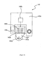
- FIG 10 is a front view showing the structure of the pressure roller mechanism 142.
- Pressure roller mechanism 142 includes therein a pressure roller 142a, air cylinder 142b, head unit 142d, slide block 142e, roller holder 142f, supporting shaft 142g, bearing 142h, and stopper 142k.
- the slide block 142e is rotatably attached on the head unit 142d, and an urging force is added thereto by means of air cylinder 142b set up on the head unit 142d.
- a roller holder 142f is attached and is rotatable around a vertical axis via bearing 142h.
- the roller holder 142f protrudes below the slide block 142e.
- the supporting shaft 142g is horizontally set up.
- the pressure roller 142a is rotatably attached to this supporting shaft 142g, and during the separating process of the mother glass substrate 90, the pressure roller 142a is opposing the roller for substrate securing 135a.
- a stopper 142k is set up on the head unit 142d, and it detects the position (height) of the head unit 142d when the pressure roller 142a makes contact with the mother glass substrate 90.
- a motor not shown
- Stopper 142k detects the change from a state wherein the slide block 142e is making contact with the stopper 142k, to a state wherein they are apart. Additionally, the stopper 142k also functions as a stopper in regards to rotation movement by the slide block 142e.
- the position of the head unit 142d in the Z direction is calculated by a control unit.
- This control unit will drive a motor so the motor vertically moves the head unit 142d.
- the position (at zero) of a vertical direction (Z direction) of the head unit 142d with respect to the glass substrate surface when the pressure roller 142a makes contact with the mother glass substrate 90 can be derived. Thereafter, the amount (distance) the pressure roller 142a will be pressing against the mother glass substrate 90 is arranged based on this detected position at zero.
- the structure of the substrate securing roller mechanism 135 is the same as, for example, the pressure roller mechanism 32 aside from the top and bottom being reversed.
- the pressing means for example, pressure roller mechanism 142
- the pressing means can be easily moved along the scribe line.
- the pressing means is a roller
- the pressing means can be easily rolled along the scribe line.
- the distortion detection unit 180 utilizes the same unit as the distortion detection unit 47 of Embodiment 2. Therefore, the unit consists of the same detection mechanisms shown in Figure 4 to detect the distortion on the surface of the mother glass substrate 90. Thus, a detailed explanation of these are omitted here.
- each of the transportation rollers 122 in each of the substrate supporting mechanisms120 are correspondingly elevated so as to protrude from the upper surface of the first securing table 121a and the second securing table 121b.
- the mother glass substrate 90 is transported onto the first securing table 121a in one side of the substrate supporting mechanism 120, and each transportation roller 122 in the substrate supporting mechanism 120 thereof supports mother glass substrate 90.
- the mother glass substrate 90 is transported onto each transportation roller 122 of the second securing table 121b in the other side of the substrate supporting mechanism 120.
- the mother glass substrate 90 becomes spanned between both substrate supporting mechanisms 120, and when the predetermined planned scribing line on the mother glass substrate 90 is transported to a predetermined position between both substrate supporting mechanisms 120, all of the transportation rollers 122 in each of the substrate supporting mechanism 120 are lowered.
- the mother glass substrate 90 still in a spanned state between the supporting tables 121 of each substrate supporting mechanisms 120, is then mounted onto both supporting tables 121.
- the vacuum pump 125 an absorption mechanism for each substrate supporting mechanism 120, is driven, and sections of the mother glass substrate 90 that are mounted on the first securing table 121a and the second securing table 121b are respectively adsorbed and fixed onto the first securing table 121a and the second securing table 121b.
- the first securing table 121a slides a micro distance (ex: 100 ⁇ m) along the Y axial direction to approach the second securing table 121b.
- internal stress is equalized along the planned scribing line in a direction towards the section of the mother glass substrate 90 between the first securing table 121a and the second securing table 121b.
- the second securing table 121b alone may also slide a micro distance along the Y axial direction, or both the first securing table 121a and the second securing table 121b may slide a micro distance along the Y axial direction to approach one another mutually.
- the control unit will calculate the tilt against the X axial direction by the mother glass substrate 90, as well as the starting position and the finishing position of scribing on the mother glass substrate 90. These calculations are based on photographic images, the glass size of the mother glass substrate 90 that are imaged by the positioning cameras 117, and positional data from the alignment marks set up on the mother glass substrate 90, as well as other factors. With these means, the planned scribing line is arranged on the mother glass substrate 90.
- the distortion detection unit 180 when the distortion detection unit 180 is moved along the planned scribing line arranged on the mother glass substrate 90, the distortion detection unit 180 is to move along the X axial direction so the irradiation line for the batch of laser light will coincide with the planned scribing line on the mother glass substrate. At the same time, each of the pillars 111 that are slidable with support from the slider 114 is to be moved along the Y axial direction. Then, the distortion detection unit 180 detects distortion on the mother glass substrate 90 (micro displacements on the surface of the mother glass substrate 90).
- the first securing table 121a and/or the second securing table 121b will be moved for a micro distance along the Y axial direction to minutely adjust the spacing between the first securing table 121a and the second securing table 121b. This will maximize the absolute value of the displacement in the Y axial direction within the range detected on the planned scribing line by the laser irradiation. The position of the mother glass substrate 90 remains unchanged even if the spacing between the first securing table 121a and the second securing table 121b are adjusted.
- Adjustments of the spacing between the first securing table 121a and the second securing table 121b are carried out so displacement is at a maximum on the surface of the mother glass substrate 90 on which the planned scribing line of the mother glass substrate is positioned. In other words, adjustments are carried out so the planned scribing line SL for the mother glass substrate 90 becomes the border line BL between the first securing table 121a and the second securing table 121b when internal stress along the Y axial direction is being equalized.
- the breaking unit 140 is slid from its stand-by position located at the end of one side(the +X side) of the upper guide rail 112, to the edge of the -X side of the mother glass substrate 90.
- the pressure roller 142a will be in a state wherein opposing the scribing start location of the mother glass substrate 90.
- the scribing unit 130 will also be slid from its stand-by position located at the end of one side (the -X side) of the lower guide rail 113 to the edge of the -X side of the scribing start location of the mother glass substrate 90.
- the cutting mechanism 134 for an incision becomes positioned beside the scribing start location of the mother glass substrate 90.
- a vertical movement motor (not shown) in the pressure roller mechanism lowers the pressure roller 142a of the breaking unit 140, and the roller is pressed onto the upper surface of the mother glass substrate 90.
- the air cylinder 134b for vertical movement elevates the cutting mechanism 134 for an incision positioned in the scribing unit 130.
- the scribing unit 130 and the breaking unit 140 are slid for a predetermined distance towards the scribing direction (+X axial direction) in synchronization with each other to form a cut on the scribing start position on the mother glass substrate 90 by means of the blade unit 134a on the cutting mechanism 134 for an incision.
- the blade unit 134a of the cutting mechanism 134 for an incision will form a cut of a prescribed length along the scribing start position of the mother glass substrate 90 while the pressure roller 142a secures the substrate.
- the pressure roller mechanism 142 is elevated while at the same time the cutting mechanism 134 for an incision of the scribing unit 130 is lowered.
- the breaking unit 140 is slid in the scribing direction (+X axial direction) for a predetermined distance, and as a result the central section of the laser beam/cooling water receiving unit 145 in the sliding direction coincides with the optical axis of the laser beam irradiation optical system 133. Furthermore, regarding the scribing unit 130, nozzle 132a on the cooling mechanism 132 will be in an upward position for spraying cooling water by means of air cylinder 136b for vertical movement.
- the scribing unit 130 and breaking unit 140 will be synchronized and slid together in the scribing direction (+X axial direction), while cooling water is sprayed upwards by the nozzle 132a and furthermore a laser beam irradiates upward from the laser beam irradiation optical system 133.
- a laser beam is irradiated along the planned scribing line SL (planned separation line) of the mother glass substrate 90, and the area near the section to which the laser was irradiated on is cooled by means of cooling water.
- the vertical cracks along the planned scribing line SL on the mother glass substrate 90 continuously generate from a cut placed on the scribing start position on the mother glass substrate 90.
- the laser beam irradiated from the laser beam irradiation optical system 133 is irradiating along the planned scribing line SL on the mother glass substrate 90 by means of the drive unit for linear interpolation.
- the drive unit for linear interpolation by means of the drive unit for linear interpolation, the upper guide rail 112 and the lower guide rail 113 are slid together with the sliding of the scribing unit 130 and the breaking unit 140, and in a direction (Y axial direction) perpendicular to the sliding direction thereof (+X axial direction).
- laser beams can irradiate along the planned scribing line SL on the mother glass substrate 90.
- the mother glass substrate is set up on the surface of the first securing table 121a and the second securing table 121b, and is suctioned by vacuum pumps and that alike from suction holes set up on the surfaces of the first securing table 121a and the second securing table 121b, and through these means suction-chucked to the first securing table 121a and the second securing table 122b, the uneven internal stresses immanent within the substrate can be equalized (organized towards the Y axial direction) by the first securing table 121a and/or the second securing table 122b moving a micro distance along the Y axial direction as mentioned above.
- the micro distance the first securing table 121a and/or the second securing table 121b travels along the Y axial direction is arranged in advance as a parameter for scribing conditions to prevent unnecessary cracks from preceding and continuously deriving on the vertical crack formed during scribing; or in other words, to prevent "forerunning" from deriving.
- Other parameters for scribing conditions include, among others, output from laser oscillators, laser beam density, scribing speed, the shape of the laser spot formed on the mother glass substrate 90 when laser beams are irradiated on the mother glass substrate 90, and intensity distribution.
- Embodiment 3 by means of moving the first securing table 121a and/or the second securing table 121b for a micro distance along the Y axial direction, the border line of the direction of the internal stress generated within the mother glass substrate 90 coincides with the planned scribing line SL.
- the abovementioned micro distance is arranged so unnecessary cracks are not forerunning during scribing.
- a vertical crack can be surely formed along the planned scribing line SL.
- the first securing table 121a and/or the second securing table 121b may also travel a micro distance along the Y axial direction to draw apart from each other mutually to form a tensile internal stress in the mother glass substrate 90.
- a continuous vertical crack is formed along the planned scribing line SL (planned separation line) of the mother glass substrate 90.
- a scribe line S is formed across the edge of one side of the mother glass substrate 90 to the edge of the other side.
- the breaking unit 140 on the upper side is slid in a direction opposite (-X axial direction) to the scribing direction, and the pressure roller 142a is arranged so it is opposing the end section of the scribe line S on the -X side.
- the scribing unit 130 on the lower side is slid so the roller for substrate securing 135a is opposing the end section of the scribe line on the -X side.
- the first auxiliary roller 136a is elevated by the air cylinder 136b for vertical movement, while the second auxiliary roller 137a is elevated by the air cylinder 137b for vertical movement and arranged to be in contact with the lower surface of the mother glass substrate 90.
- the roller for substrate securing 135a is elevated with the motor (not shown) that vertically moves the head unit 135b, and is arranged to be in contact at a predetermined pressure with the lower surface of the mother glass substrate 90.
- the pressing-side first auxiliary roller 143a of the breaking unit 140 is lowered to be in contact with a section on the upper surface of the mother glass substrate 90 that is opposing the position that the second auxiliary roller 137a of the scribing unit 130 is in contact with. Furthermore, pressure roller 142a is lowered by the motor (not shown) that vertically moves the head unit 142b, and the pressure roller 142a is arranged so as to be pressed at a predetermined pressure onto a section on the upper surface of the mother glass substrate 90 that opposes the roller for substrate securing 135a.
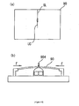
- Figure 11 is a figure showing a condition wherein the pressure roller 142a is pressed at a predetermined pressure onto a section on the upper surface of the mother glass substrate 90.
- the roller for substrate securing 135a arranged on the lower side of the mother glass substrate 90, is in a state wherein its outer periphery surface has a V-shaped depression therein.
- the roller will also be in a state wherein both sides of its flat marginal sections in the width direction are correspondingly pressing on both sides of the scribe line S formed on the mother glass substrate 90.
- a U-shaped groove section 45g is formed on the central section in the width direction thereof. The central section of this groove section opposes the scribe line S formed on the mother glass substrate 90.
- the dimensions in the width direction of the pressure roller 142a are approximately 1 ⁇ 2 of what the dimensions are for the width direction of the roller for substrate securing 135a. Due to this, the pressure roller 142a will be pressing onto a section on the upper surface of the mother glass substrate 90 near the scribe line S, rather than a section on the lower surface of the mother glass substrate 90 secured by both sides of the marginal sections of the roller for substrate securing 135a. In this case, the pressure roller 142a is arranged to reach a lowered position that is, for example, over 0.3mm below the upper surface of the mother glass substrate 90, and is thus pressed onto the upper surface of the mother glass substrate 90.
- the pressure roller 142a presses onto a section of the upper surface of the mother glass substrate 90 near the scribe line S, rather than a section of the lower surface of the mother glass substrate 90 being secured by both sides of the marginal sections on the roller for substrate securing 135a. Due to this, the mother glass substrate 90 is in a bent state protruded downwards with scribe line S at its center. The vertical crack on the end of the -X side of the scribe line S formed on the lower surface of the mother glass substrate 90 will then extend toward the thickness direction of the glass substrate, and reach the upper surface of the mother glass substrate 90. From the above described process, the mother glass substrate 90 is separated (broken).
- the pressure roller 142a is slightly elevated and the pressing against the mother glass substrate 90 by the pressure roller 142a is slightly weakened.
- the pressure roller 142a is arranged to reach a lowered position that is within 0.3mm of the upper surface of the mother glass substrate 90.
- the pressing-side second auxiliary roller 144a is lowered onto the mother glass substrate 90 opposing the first auxiliary roller 136a of the scribing unit 130.
- sections on both sides on the scribe line S secured by the roller for substrate securing 135a are pressed by the pressure roller 142a.
- the roller for substrate securing 135a and the pressure roller 142a then correspondingly roll on the lower surface and upper surface of the mother glass substrate 90, and the mother glass substrate is continuously separated along the scribe line S starting from the position at the end section of the scribe line on the -X side.
- the pressing-side first auxiliary roller 143a and the second auxiliary roller 137a, both positioned in front of the pressure roller 142a in the sliding direction, and the pressing-side second auxiliary roller 144a and the first auxiliary roller 136a, both positioned behind pressure roller 142a in the sliding direction, will press and secure from top and bottom the region in front of the scribe line S for separation as well as the mother glass substrate 90 after separation. Due to this, when the mother glass substrate 90 is broken (separated) along the scribe line S by pressing means of the pressure roller 142a, unnecessary force is not applied to sections of the mother glass substrate 90 for the separation procedure. Therefore, chipping, cuts, fractures and alike that are factors in causing malfunctions by products after the mother glass substrate 90 is separated, are prevented from generating.
- the mother glass substrate 90 that is separated along the scribe line during the breaking (separating) process of the mother glass substrate 90 is secured by means of the first auxiliary roller 136a and the pressing-side second auxiliary roller 144a provided with predetermined spacing from the roller for substrate securing 135a in the scribing unit 130. Therefore, the separated mother glass substrate 90 is prevented from bending, chipping, cuts, fractures a and alike that are potential factors for causing malfunctions by products after the mother glass substrate 90 is separated, are prevented from generating.
- the mother glass substrate 90 is separated along the entire region of the scribe line.
- the scribing unit 130, the second auxiliary roller 137a, the roller for substrate securing 135a, and the first auxiliary roller 136a are all lowered, resulting in all of the rollers becoming detached from the lower surface of the mother glass substrate 90.
- the breaking unit 140 the pressing-side first auxiliary roller 143a is elevated, while pressure roller 142a and pressing-side second auxiliary roller 144a are also elevated, and thus these rollers too become detached from the mother glass substrate 90.
- the scribing unit 130 and the breaking unit 140 are correspondingly slid and arranged in the stand-by positions at the end sections of the upper guide rail 112 and the lower guide rail 113.
- a scribe line S can be surely formed along the planned scribing line SL by means of the separation system of brittle material substrates in Embodiment 3.
- the mother glass substrate 90 on which the scribe line S was formed can also be surely separated along the scribe line S. Furthermore, since the mother glass substrate 90 can be continuously separated along a formation of the scribe line S, work efficiency is improved. Also, when separating the mother glass substrate 90, there is no concern of fractures, chipping and those alike generating on the separated surface.
- the breaking unit 140 is slidably attached to the upper guide rail 112, and the scribing unit 130 is slidably attached to the lower guide rail 113.
- the Embodiment should not be limited to this, and the breaking unit 140 may be slidably attached to the lower guide rail 113, and the scribing unit 130 may be slidably attached to the upper guide rail 112.
- the separation system for brittle material substrate of the present invention (separation system 100 for brittle material substrate), under conditions wherein the securing means (substrate securing roller mechanism 135) secures the first principle surface of the brittle material substrate (mother glass substrate 90), and the pressing means (pressure roller mechanism 142) presses the second principle surface of the brittle material substrate; since the pressing means can be moved along the scribe line S formed on the first principle surface of the brittle material substrate by utilizing the scribing method of the present invention, applied pressure can be employed against the second principle surface opposing the first principle surface on which the scribe line S is formed. As a result, the vertical crack produced from the scribe line S can be surely extended towards the thickness direction of the substrate by a bending momentum that can be applied to the brittle material substrate. Thus, the brittle material substrate can be separated.
- Embodiments 1 through 3 as a brittle material substrate a mother glass substrate that structures liquid crystal display panel substrates, which is a type of flat panel display was described, Also, scribing methods employing this substrate as well as scribing apparatuses utilizing methods thereof and separation methods and separation systems utilizing methods thereof were described.
- the present invention should not be limited to this structure, and single panel brittle substrates such as quartz substrates, sphere substrates, semiconductor wafers, and ceramic substrates may also be applied to the present invention.
- a wheel cutter that rolls along the planned scribing line SL was exemplified.
- a laser beam may be irradiated instead along the planned scribing line SL to form the scribe line S.
- a scribing line is formed by irradiating a laser beam as a means of forming a scribing line S.
- a scribing line may be also formed by rotating a wheel cutter along a planned scribing line SL.
- the internal stress near the planned scribing line is equalized and an unnecessary crack can be prevented from deriving from the vertical crack formed on the mother glass substrate by forming a micro distortion from compressing or pulling a mother glass substrate being suction-chucked.
- the internal stress that the said substrate possesses which extends towards unspecified directions is equalized, and an accurate vertical crack can be formed along the planned scribing line by forming a micro distortion on the mother glass substrate.
- the internal stress near the planned scribing line can be equalized.
- adsorption securing mechanisms conventionally utilized to secure mother glass substrates can be employed. Therefore, there is no need to separately set up a sophisticated mechanism for internal stress equalization.
- the region of a substrate on which the internal stress has been equalized can be precisely scribed thereon.
- the present invention applies to a scribing method for single panel brittle material substrates such as quartz substrates, sphere substrates, semiconductor wafers, and ceramic substrates, wherein the scribing method scribes along a planned scribing line thereof.
- the present invention also applies to a separation system consisting of a scribing apparatus and a breaking mechanism utilizing the scribing method thereof.
- brittle material substrates different types of flat display panels such as plasma display panels, organic electroluminescence display panels, inorganic electroluminescence display panels, transmissive projector substrates, and reflective projector substrates that are either bonding substrates or single panel substrates may also effectively apply the scribing method of the present invention and the scribing apparatus utilizing the method thereof, as well as the separation method and the separation system utilizing the method thereof.
- the yield rates of the separation work of such brittle material substrates can be significantly improved by precisely forming a scribe line along the planned scribe line thereon. Furthermore, unnecessary cracks that are out of alignment with the planned scribe line arranged in advance can be prevented from continuously deriving out of vertical cracks formed on the brittle material substrate by means of the said scribing method.
Landscapes
- Chemical & Material Sciences (AREA)
- Engineering & Computer Science (AREA)
- Materials Engineering (AREA)
- Organic Chemistry (AREA)
- Mechanical Engineering (AREA)
- Re-Forming, After-Treatment, Cutting And Transporting Of Glass Products (AREA)
- Processing Of Stones Or Stones Resemblance Materials (AREA)
Applications Claiming Priority (2)
| Application Number | Priority Date | Filing Date | Title |
|---|---|---|---|
| JP2004299446 | 2004-10-13 | ||
| PCT/JP2005/018475 WO2006040988A1 (ja) | 2004-10-13 | 2005-10-05 | 脆性材料基板のスクライブ方法ならびにスクライブ装置および脆性材料基板の分断システム |
Publications (3)
| Publication Number | Publication Date |
|---|---|
| EP1800820A1 EP1800820A1 (en) | 2007-06-27 |
| EP1800820A4 EP1800820A4 (en) | 2011-02-23 |
| EP1800820B1 true EP1800820B1 (en) | 2012-12-12 |
Family
ID=36148283
Family Applications (1)
| Application Number | Title | Priority Date | Filing Date |
|---|---|---|---|
| EP05790181A Expired - Lifetime EP1800820B1 (en) | 2004-10-13 | 2005-10-05 | Method and apparatus for scribing brittle material board and system for breaking brittle material board |
Country Status (7)
| Country | Link |
|---|---|
| US (1) | US20090050610A1 (enExample) |
| EP (1) | EP1800820B1 (enExample) |
| JP (1) | JP4818120B2 (enExample) |
| KR (1) | KR100893871B1 (enExample) |
| CN (1) | CN101068666B (enExample) |
| TW (1) | TW200624396A (enExample) |
| WO (1) | WO2006040988A1 (enExample) |
Families Citing this family (51)
| Publication number | Priority date | Publication date | Assignee | Title |
|---|---|---|---|---|
| JP2009126780A (ja) * | 2007-11-21 | 2009-06-11 | Semes Co Ltd | スクライブ装置並びに方法、及びこれを利用した基板切断装置 |
| TWI435850B (zh) * | 2008-01-23 | 2014-05-01 | Mitsuboshi Diamond Ind Co Ltd | Scribing device and scribing method |
| KR100989125B1 (ko) * | 2008-07-16 | 2010-10-20 | 삼성모바일디스플레이주식회사 | 원장기판 절단 장치 및 이에 의하여 절단된 유기발광표시장치 |
| JP5167160B2 (ja) * | 2009-01-30 | 2013-03-21 | 三星ダイヤモンド工業株式会社 | 脆性材料基板の搬送・分断装置 |
| JP5249979B2 (ja) * | 2010-03-18 | 2013-07-31 | 三星ダイヤモンド工業株式会社 | 脆性材料基板の加工方法およびこれに用いるレーザ加工装置 |
| JP5508133B2 (ja) * | 2010-05-19 | 2014-05-28 | 株式会社ディスコ | 板状物の分割装置 |
| KR101356217B1 (ko) * | 2011-12-20 | 2014-01-29 | 참엔지니어링(주) | 기판 트리밍 장치 및 방법 |
| KR101407976B1 (ko) * | 2012-05-04 | 2014-07-03 | 코닝정밀소재 주식회사 | 실시간 파손 감지 기능을 구비한 유리기판용 레이저 절단 장치 및 이의 유리기판 파손 감지 방법 |
| CN102674676A (zh) * | 2012-05-17 | 2012-09-19 | 东莞宏威数码机械有限公司 | 基片切割装置 |
| JP6043149B2 (ja) * | 2012-10-29 | 2016-12-14 | 三星ダイヤモンド工業株式会社 | 脆性材料基板のブレイク装置および脆性材料基板のブレイク方法 |
| CN103056976B (zh) * | 2012-12-27 | 2015-07-22 | 东莞市拓荒牛自动化设备有限公司 | 一种led导光板刻线方法及实施该方法的刻线机 |
| US9434085B2 (en) * | 2013-06-04 | 2016-09-06 | Shenzhen China Star Optoelectronics Technology Co., Ltd | Cutting system for glass substrate |
| CN103288342B (zh) * | 2013-06-04 | 2015-06-03 | 深圳市华星光电技术有限公司 | 一种玻璃基板切割系统 |
| JP2015034111A (ja) * | 2013-08-09 | 2015-02-19 | 三星ダイヤモンド工業株式会社 | 積層セラミックス基板の分断方法 |
| EP3155556B1 (en) | 2014-06-10 | 2019-12-18 | Sicpa Holding SA | Substrate with a fragmented marking thereon |
| EP2990388B1 (en) * | 2014-08-26 | 2019-01-30 | Mecánicas Teruel S.L. | Cutting device for a cutting table |
| KR101648010B1 (ko) * | 2015-03-03 | 2016-08-17 | 한국미쯔보시다이아몬드공업(주) | 스크라이브 라인 형성 방법 |
| DE102015211017B4 (de) * | 2015-06-16 | 2017-06-14 | Trumpf Werkzeugmaschinen Gmbh + Co. Kg | Verfahren zum hauptzeitparallelen Entladen eines freigeschnittenen Werkstückteils, zugehörige Laserschneidmaschine und Computerprogrammprodukt |
| JP6610026B2 (ja) * | 2015-06-23 | 2019-11-27 | 三星ダイヤモンド工業株式会社 | スクライブ装置 |
| CN106891094A (zh) * | 2015-12-14 | 2017-06-27 | 上海申和热磁电子有限公司 | 用于覆铜陶瓷基板的激光切割机工作台 |
| JP6699196B2 (ja) * | 2016-01-22 | 2020-05-27 | 三星ダイヤモンド工業株式会社 | ブレイク装置 |
| CN105643823B (zh) * | 2016-03-18 | 2017-11-07 | 郑招才 | 一种陶瓷简易切割装置四轴移动机架 |
| CN105619633B (zh) * | 2016-03-18 | 2017-11-07 | 管敏富 | 一种陶瓷简易切割装置用移动架 |
| CN105599151B (zh) * | 2016-03-18 | 2017-09-29 | 德化开元瓷业有限公司 | 一种陶瓷简易切割装置 |
| CN107225697B (zh) * | 2016-03-18 | 2019-04-02 | 唐山国新赛隆科技有限公司 | 一种气缸推动式陶瓷简易切割装置及其工作方法 |
| CN205874212U (zh) * | 2016-07-21 | 2017-01-11 | 京东方科技集团股份有限公司 | 切割刀头以及切割装置 |
| CN106114983B (zh) * | 2016-08-11 | 2018-05-22 | 新昌县远通农业发展有限公司 | 一种化妆品盒输送架抓取输送机构 |
| CN106114980B (zh) * | 2016-08-11 | 2018-05-29 | 新昌县远通农业发展有限公司 | 一种化妆品盒输送架搬运输送自动提升机构 |
| CN106081249B (zh) * | 2016-08-11 | 2018-05-25 | 台州市黄岩昱通塑业有限公司 | 一种化妆品盒输送架搬运输送机构 |
| CN106696102A (zh) * | 2016-12-05 | 2017-05-24 | 无锡明珠增压器制造有限公司 | 一种精确控制硅片切片装置 |
| CN106514885A (zh) * | 2016-12-05 | 2017-03-22 | 无锡明珠增压器制造有限公司 | 一种硅棒自动切片机 |
| KR101899679B1 (ko) * | 2016-12-21 | 2018-09-17 | 주식회사 포스코 | 시료 고정장치 |
| CN106626109A (zh) * | 2016-12-21 | 2017-05-10 | 日照市奥大力精密设备有限公司 | 一种智能玻璃上片切割一体机 |
| DE102017007585A1 (de) | 2017-08-11 | 2019-02-14 | Siltectra Gmbh | Vorrichtung und Verfahren zum Beaufschlagen von Spannungserzeugungsschichten mit Druck zum verbesserten Führen eines Abtrennrisses |
| KR101980606B1 (ko) * | 2017-08-29 | 2019-05-21 | 한국미쯔보시다이아몬드공업(주) | 취성 재료 기판의 경사 타입 분단 장치 및 분단 방법 |
| CN107352786A (zh) * | 2017-08-30 | 2017-11-17 | 蚌埠朝阳玻璃机械有限公司 | Tft视觉定位精密光电玻璃切割机 |
| JP6967276B2 (ja) * | 2017-12-28 | 2021-11-17 | 三星ダイヤモンド工業株式会社 | ブレーク装置 |
| JP2020066539A (ja) * | 2018-10-22 | 2020-04-30 | 坂東機工株式会社 | ガラス板の折割機械 |
| TWI797352B (zh) * | 2018-10-30 | 2023-04-01 | 日商三星鑽石工業股份有限公司 | 裂斷裝置 |
| CN109524332B (zh) * | 2018-12-26 | 2020-10-20 | 江苏纳沛斯半导体有限公司 | 一种半导体晶圆精准切割装置 |
| KR102122427B1 (ko) * | 2019-01-09 | 2020-06-12 | 한국미쯔보시다이아몬드공업(주) | 단재 제거 장치 |
| JP7228883B2 (ja) * | 2019-01-30 | 2023-02-27 | 三星ダイヤモンド工業株式会社 | 分断方法およびブレイク方法 |
| CN111908780A (zh) * | 2019-05-10 | 2020-11-10 | 塔工程有限公司 | 划线装置及其控制方法 |
| ES2799998A1 (es) * | 2019-06-21 | 2020-12-22 | Univ Valladolid | Aparato y procedimiento para la realizacion de grietas controladas en muestras de silicio monocristalino y multicristalino |
| CN110282867B (zh) * | 2019-08-01 | 2023-08-01 | 中电科风华信息装备股份有限公司 | 一种多刀划线机的异形划线结构 |
| CN110556320B (zh) * | 2019-09-12 | 2021-11-30 | 常州时创能源股份有限公司 | 硅片分割装置及分割方法 |
| CN110590147B (zh) * | 2019-09-18 | 2022-08-02 | 彩虹(合肥)液晶玻璃有限公司 | 分离方法、装置、设备和切割设备 |
| CN110978086B (zh) * | 2019-12-24 | 2021-07-20 | 上饶市晶鑫光学元件有限公司 | 一种光学器材用镜片切割装置 |
| JP7098173B2 (ja) * | 2020-02-12 | 2022-07-11 | 三星ダイヤモンド工業株式会社 | 脆性材料基板の分断機構 |
| CN114454240B (zh) * | 2022-04-11 | 2022-06-17 | 中国空气动力研究与发展中心高速空气动力研究所 | 一种激波管膜片的划刻装置及划刻方法 |
| KR102876109B1 (ko) * | 2024-08-28 | 2025-10-28 | 주식회사 에스피오엠 | 렌즈 제작용 글라스 가공 장치 |
Family Cites Families (25)
| Publication number | Priority date | Publication date | Assignee | Title |
|---|---|---|---|---|
| DE2404840C3 (de) * | 1974-02-01 | 1978-08-31 | Wunderlich, Christian, 4057 Brueggen | Verfahren zur Trennung von in einem Bogen zusammenhängenden Nutzenabschnitten und Vorrichtung zur Durchführung des Verfahrens |
| JPS5918123A (ja) * | 1982-07-20 | 1984-01-30 | Nippon Electric Glass Co Ltd | 厚板ガラスの切断方法 |
| US4653680A (en) * | 1985-04-25 | 1987-03-31 | Regan Barrie F | Apparatus for breaking semiconductor wafers and the like |
| JPH01179770A (ja) * | 1988-01-12 | 1989-07-17 | Hiroshima Denki Gakuen | 金属とセラミックスとの接合方法 |
| US5303861A (en) * | 1992-09-01 | 1994-04-19 | Corning Incorporated | Separating sheet glass |
| JPH06144860A (ja) * | 1992-11-11 | 1994-05-24 | Fuji Xerox Co Ltd | 脆性板用スクライブ装置 |
| JP2700136B2 (ja) * | 1994-06-02 | 1998-01-19 | 双栄通商株式会社 | 脆性材料の割断方法 |
| JP3847864B2 (ja) * | 1995-11-21 | 2006-11-22 | 三星ダイヤモンド工業株式会社 | ガラススクライバー |
| JPH1071483A (ja) * | 1996-08-29 | 1998-03-17 | Hitachi Constr Mach Co Ltd | 脆性材料の割断方法 |
| JPH1179770A (ja) * | 1997-07-10 | 1999-03-23 | Yamaha Corp | スクライブ装置及び劈開方法 |
| JP3326384B2 (ja) * | 1998-03-12 | 2002-09-24 | 古河電気工業株式会社 | 半導体ウエハーの劈開方法およびその装置 |
| JP2002050589A (ja) * | 2000-08-03 | 2002-02-15 | Sony Corp | 半導体ウェーハの延伸分離方法及び装置 |
| TW536527B (en) * | 2000-08-11 | 2003-06-11 | Mitsuboshi Diamond Ind Co Ltd | Cutter for cutting brittle material, scriber using the same and scribing method |
| JP2003286044A (ja) * | 2002-03-27 | 2003-10-07 | Sharp Corp | 基板分断装置および基板分断方法 |
| KR100724474B1 (ko) | 2002-10-22 | 2007-06-04 | 엘지.필립스 엘시디 주식회사 | 액정 표시패널의 절단 장치 및 이를 이용한 절단방법 |
| WO2004041493A1 (ja) * | 2002-11-06 | 2004-05-21 | Mitsuboshi Diamond Industrial Co.,Ltd. | スクライブライン形成装置及びスクライブライン形成方法 |
| US20040187523A1 (en) * | 2003-03-24 | 2004-09-30 | Corning Incorporated | Score bar instrumented with a force sensor |
| SG116533A1 (en) * | 2003-03-26 | 2005-11-28 | Toshiba Kk | Semiconductor manufacturing apparatus and method of manufacturing semiconductor device. |
| US7770500B2 (en) * | 2004-03-15 | 2010-08-10 | Mitsuboshi Diamond Industrial Co., Ltd. | Substrate dividing system, substrate manufacturing equipment, substrate scribing method and substrate dividing method |
| JP4511903B2 (ja) * | 2004-10-20 | 2010-07-28 | 株式会社ディスコ | ウエーハの分割装置 |
| KR101096733B1 (ko) * | 2004-12-27 | 2011-12-21 | 엘지디스플레이 주식회사 | 기판의 절단장치 및 이를 이용한 기판의 절단방법 |
| JP5037138B2 (ja) * | 2005-01-05 | 2012-09-26 | Thk株式会社 | ワークのブレイク方法及び装置、スクライブ及びブレイク方法、並びにブレイク機能付きスクライブ装置 |
| JP2006199553A (ja) * | 2005-01-24 | 2006-08-03 | Sharp Corp | 基板分断装置及び基板分断方法 |
| US20060249553A1 (en) * | 2005-05-06 | 2006-11-09 | Ljerka Ukrainczyk | Ultrasonic induced crack propagation in a brittle material |
| US8656738B2 (en) * | 2008-10-31 | 2014-02-25 | Corning Incorporated | Glass sheet separating device |
-
2005
- 2005-10-05 JP JP2006540898A patent/JP4818120B2/ja not_active Expired - Fee Related
- 2005-10-05 KR KR1020077010736A patent/KR100893871B1/ko not_active Expired - Fee Related
- 2005-10-05 EP EP05790181A patent/EP1800820B1/en not_active Expired - Lifetime
- 2005-10-05 CN CN2005800390656A patent/CN101068666B/zh not_active Expired - Fee Related
- 2005-10-05 US US11/577,117 patent/US20090050610A1/en not_active Abandoned
- 2005-10-05 WO PCT/JP2005/018475 patent/WO2006040988A1/ja not_active Ceased
- 2005-10-13 TW TW094135617A patent/TW200624396A/zh not_active IP Right Cessation
Also Published As
| Publication number | Publication date |
|---|---|
| TW200624396A (en) | 2006-07-16 |
| US20090050610A1 (en) | 2009-02-26 |
| JP4818120B2 (ja) | 2011-11-16 |
| CN101068666B (zh) | 2011-05-04 |
| KR20070067200A (ko) | 2007-06-27 |
| EP1800820A4 (en) | 2011-02-23 |
| WO2006040988A1 (ja) | 2006-04-20 |
| CN101068666A (zh) | 2007-11-07 |
| TWI374862B (enExample) | 2012-10-21 |
| KR100893871B1 (ko) | 2009-04-20 |
| EP1800820A1 (en) | 2007-06-27 |
| JPWO2006040988A1 (ja) | 2008-05-15 |
Similar Documents
| Publication | Publication Date | Title |
|---|---|---|
| EP1800820B1 (en) | Method and apparatus for scribing brittle material board and system for breaking brittle material board | |
| JP4464961B2 (ja) | 基板分断システム、基板製造装置、基板スクライブ方法および基板分断方法 | |
| KR100949152B1 (ko) | 유리 기판 레이저 절단 장치 | |
| US7426883B2 (en) | Substrate-cutting system, substrate-producing apparatus, substrate-scribing method, and substrate-cutting method | |
| US7131562B2 (en) | Scribing and breaking apparatus, system therefor, and scribing and breaking method | |
| EP1731261B1 (en) | Vertical working line for plate material | |
| US7845529B2 (en) | Method for processing substrate, apparatus for processing substrate, method for conveying substrate and mechanism for conveying substrate | |
| CN103030263B (zh) | 母基板的分断方法 | |
| US20070051769A1 (en) | Brittle substrate cutting system and brittle substrate cutting method | |
| JP6364789B2 (ja) | スクライブ装置 | |
| JP2010023071A (ja) | 貼り合わせ基板の端子加工方法 | |
| KR100863438B1 (ko) | 다축 동기 제어를 이용한 스크라이브 장치 및 그 방법 | |
| JP6251061B2 (ja) | 脆性材料基板のスクライブ装置 | |
| TW201532989A (zh) | 劃線裝置 | |
| US20100089961A1 (en) | Apparatus and method of cutting liquid crystal display device | |
| KR102114025B1 (ko) | 기판 절단 장치 | |
| KR20200088928A (ko) | 더미 제거 유닛 및 더미 제거 방법 |
Legal Events
| Date | Code | Title | Description |
|---|---|---|---|
| PUAI | Public reference made under article 153(3) epc to a published international application that has entered the european phase |
Free format text: ORIGINAL CODE: 0009012 |
|
| 17P | Request for examination filed |
Effective date: 20070412 |
|
| AK | Designated contracting states |
Kind code of ref document: A1 Designated state(s): AT BE BG CH CY CZ DE DK EE ES FI FR GB GR HU IE IS IT LI LT LU LV MC NL PL PT RO SE SI SK TR |
|
| DAX | Request for extension of the european patent (deleted) | ||
| A4 | Supplementary search report drawn up and despatched |
Effective date: 20110121 |
|
| 17Q | First examination report despatched |
Effective date: 20111005 |
|
| GRAP | Despatch of communication of intention to grant a patent |
Free format text: ORIGINAL CODE: EPIDOSNIGR1 |
|
| RIN1 | Information on inventor provided before grant (corrected) |
Inventor name: OTODA, KENJI, MITSUBOSHI DIAMOND INDUSTRIAL CO., L Inventor name: TAKAMATSU, KIYOSHI, MITSUBOSHI DIAMOND IND. CO., L |
|
| GRAS | Grant fee paid |
Free format text: ORIGINAL CODE: EPIDOSNIGR3 |
|
| GRAA | (expected) grant |
Free format text: ORIGINAL CODE: 0009210 |
|
| AK | Designated contracting states |
Kind code of ref document: B1 Designated state(s): AT BE BG CH CY CZ DE DK EE ES FI FR GB GR HU IE IS IT LI LT LU LV MC NL PL PT RO SE SI SK TR |
|
| REG | Reference to a national code |
Ref country code: GB Ref legal event code: FG4D |
|
| REG | Reference to a national code |
Ref country code: CH Ref legal event code: EP |
|
| REG | Reference to a national code |
Ref country code: AT Ref legal event code: REF Ref document number: 588108 Country of ref document: AT Kind code of ref document: T Effective date: 20121215 |
|
| REG | Reference to a national code |
Ref country code: IE Ref legal event code: FG4D |
|
| REG | Reference to a national code |
Ref country code: DE Ref legal event code: R096 Ref document number: 602005037425 Country of ref document: DE Effective date: 20130207 |
|
| PG25 | Lapsed in a contracting state [announced via postgrant information from national office to epo] |
Ref country code: LT Free format text: LAPSE BECAUSE OF FAILURE TO SUBMIT A TRANSLATION OF THE DESCRIPTION OR TO PAY THE FEE WITHIN THE PRESCRIBED TIME-LIMIT Effective date: 20121212 Ref country code: SE Free format text: LAPSE BECAUSE OF FAILURE TO SUBMIT A TRANSLATION OF THE DESCRIPTION OR TO PAY THE FEE WITHIN THE PRESCRIBED TIME-LIMIT Effective date: 20121212 Ref country code: ES Free format text: LAPSE BECAUSE OF FAILURE TO SUBMIT A TRANSLATION OF THE DESCRIPTION OR TO PAY THE FEE WITHIN THE PRESCRIBED TIME-LIMIT Effective date: 20130323 Ref country code: FI Free format text: LAPSE BECAUSE OF FAILURE TO SUBMIT A TRANSLATION OF THE DESCRIPTION OR TO PAY THE FEE WITHIN THE PRESCRIBED TIME-LIMIT Effective date: 20121212 |
|
| REG | Reference to a national code |
Ref country code: NL Ref legal event code: VDEP Effective date: 20121212 |
|
| REG | Reference to a national code |
Ref country code: AT Ref legal event code: MK05 Ref document number: 588108 Country of ref document: AT Kind code of ref document: T Effective date: 20121212 |
|
| REG | Reference to a national code |
Ref country code: LT Ref legal event code: MG4D |
|
| PG25 | Lapsed in a contracting state [announced via postgrant information from national office to epo] |
Ref country code: GR Free format text: LAPSE BECAUSE OF FAILURE TO SUBMIT A TRANSLATION OF THE DESCRIPTION OR TO PAY THE FEE WITHIN THE PRESCRIBED TIME-LIMIT Effective date: 20130313 Ref country code: SI Free format text: LAPSE BECAUSE OF FAILURE TO SUBMIT A TRANSLATION OF THE DESCRIPTION OR TO PAY THE FEE WITHIN THE PRESCRIBED TIME-LIMIT Effective date: 20121212 Ref country code: LV Free format text: LAPSE BECAUSE OF FAILURE TO SUBMIT A TRANSLATION OF THE DESCRIPTION OR TO PAY THE FEE WITHIN THE PRESCRIBED TIME-LIMIT Effective date: 20121212 |
|
| PG25 | Lapsed in a contracting state [announced via postgrant information from national office to epo] |
Ref country code: CZ Free format text: LAPSE BECAUSE OF FAILURE TO SUBMIT A TRANSLATION OF THE DESCRIPTION OR TO PAY THE FEE WITHIN THE PRESCRIBED TIME-LIMIT Effective date: 20121212 Ref country code: AT Free format text: LAPSE BECAUSE OF FAILURE TO SUBMIT A TRANSLATION OF THE DESCRIPTION OR TO PAY THE FEE WITHIN THE PRESCRIBED TIME-LIMIT Effective date: 20121212 Ref country code: BG Free format text: LAPSE BECAUSE OF FAILURE TO SUBMIT A TRANSLATION OF THE DESCRIPTION OR TO PAY THE FEE WITHIN THE PRESCRIBED TIME-LIMIT Effective date: 20130312 Ref country code: SK Free format text: LAPSE BECAUSE OF FAILURE TO SUBMIT A TRANSLATION OF THE DESCRIPTION OR TO PAY THE FEE WITHIN THE PRESCRIBED TIME-LIMIT Effective date: 20121212 Ref country code: IS Free format text: LAPSE BECAUSE OF FAILURE TO SUBMIT A TRANSLATION OF THE DESCRIPTION OR TO PAY THE FEE WITHIN THE PRESCRIBED TIME-LIMIT Effective date: 20130412 Ref country code: BE Free format text: LAPSE BECAUSE OF FAILURE TO SUBMIT A TRANSLATION OF THE DESCRIPTION OR TO PAY THE FEE WITHIN THE PRESCRIBED TIME-LIMIT Effective date: 20121212 Ref country code: EE Free format text: LAPSE BECAUSE OF FAILURE TO SUBMIT A TRANSLATION OF THE DESCRIPTION OR TO PAY THE FEE WITHIN THE PRESCRIBED TIME-LIMIT Effective date: 20121212 |
|
| PG25 | Lapsed in a contracting state [announced via postgrant information from national office to epo] |
Ref country code: PT Free format text: LAPSE BECAUSE OF FAILURE TO SUBMIT A TRANSLATION OF THE DESCRIPTION OR TO PAY THE FEE WITHIN THE PRESCRIBED TIME-LIMIT Effective date: 20130412 Ref country code: NL Free format text: LAPSE BECAUSE OF FAILURE TO SUBMIT A TRANSLATION OF THE DESCRIPTION OR TO PAY THE FEE WITHIN THE PRESCRIBED TIME-LIMIT Effective date: 20121212 Ref country code: PL Free format text: LAPSE BECAUSE OF FAILURE TO SUBMIT A TRANSLATION OF THE DESCRIPTION OR TO PAY THE FEE WITHIN THE PRESCRIBED TIME-LIMIT Effective date: 20121212 Ref country code: RO Free format text: LAPSE BECAUSE OF FAILURE TO SUBMIT A TRANSLATION OF THE DESCRIPTION OR TO PAY THE FEE WITHIN THE PRESCRIBED TIME-LIMIT Effective date: 20121212 |
|
| PLBE | No opposition filed within time limit |
Free format text: ORIGINAL CODE: 0009261 |
|
| STAA | Information on the status of an ep patent application or granted ep patent |
Free format text: STATUS: NO OPPOSITION FILED WITHIN TIME LIMIT |
|
| PG25 | Lapsed in a contracting state [announced via postgrant information from national office to epo] |
Ref country code: DK Free format text: LAPSE BECAUSE OF FAILURE TO SUBMIT A TRANSLATION OF THE DESCRIPTION OR TO PAY THE FEE WITHIN THE PRESCRIBED TIME-LIMIT Effective date: 20121212 |
|
| 26N | No opposition filed |
Effective date: 20130913 |
|
| PG25 | Lapsed in a contracting state [announced via postgrant information from national office to epo] |
Ref country code: CY Free format text: LAPSE BECAUSE OF FAILURE TO SUBMIT A TRANSLATION OF THE DESCRIPTION OR TO PAY THE FEE WITHIN THE PRESCRIBED TIME-LIMIT Effective date: 20121212 |
|
| PG25 | Lapsed in a contracting state [announced via postgrant information from national office to epo] |
Ref country code: IT Free format text: LAPSE BECAUSE OF FAILURE TO SUBMIT A TRANSLATION OF THE DESCRIPTION OR TO PAY THE FEE WITHIN THE PRESCRIBED TIME-LIMIT Effective date: 20121212 |
|
| REG | Reference to a national code |
Ref country code: DE Ref legal event code: R097 Ref document number: 602005037425 Country of ref document: DE Effective date: 20130913 |
|
| PGFP | Annual fee paid to national office [announced via postgrant information from national office to epo] |
Ref country code: DE Payment date: 20131030 Year of fee payment: 9 Ref country code: GB Payment date: 20131022 Year of fee payment: 9 Ref country code: FR Payment date: 20131018 Year of fee payment: 9 |
|
| PG25 | Lapsed in a contracting state [announced via postgrant information from national office to epo] |
Ref country code: MC Free format text: LAPSE BECAUSE OF FAILURE TO SUBMIT A TRANSLATION OF THE DESCRIPTION OR TO PAY THE FEE WITHIN THE PRESCRIBED TIME-LIMIT Effective date: 20121212 |
|
| REG | Reference to a national code |
Ref country code: CH Ref legal event code: PL |
|
| REG | Reference to a national code |
Ref country code: IE Ref legal event code: MM4A |
|
| PG25 | Lapsed in a contracting state [announced via postgrant information from national office to epo] |
Ref country code: CH Free format text: LAPSE BECAUSE OF NON-PAYMENT OF DUE FEES Effective date: 20131031 Ref country code: LI Free format text: LAPSE BECAUSE OF NON-PAYMENT OF DUE FEES Effective date: 20131031 |
|
| PG25 | Lapsed in a contracting state [announced via postgrant information from national office to epo] |
Ref country code: IE Free format text: LAPSE BECAUSE OF NON-PAYMENT OF DUE FEES Effective date: 20131005 |
|
| REG | Reference to a national code |
Ref country code: DE Ref legal event code: R119 Ref document number: 602005037425 Country of ref document: DE |
|
| GBPC | Gb: european patent ceased through non-payment of renewal fee |
Effective date: 20141005 |
|
| PG25 | Lapsed in a contracting state [announced via postgrant information from national office to epo] |
Ref country code: TR Free format text: LAPSE BECAUSE OF FAILURE TO SUBMIT A TRANSLATION OF THE DESCRIPTION OR TO PAY THE FEE WITHIN THE PRESCRIBED TIME-LIMIT Effective date: 20121212 |
|
| PG25 | Lapsed in a contracting state [announced via postgrant information from national office to epo] |
Ref country code: DE Free format text: LAPSE BECAUSE OF NON-PAYMENT OF DUE FEES Effective date: 20150501 Ref country code: LU Free format text: LAPSE BECAUSE OF NON-PAYMENT OF DUE FEES Effective date: 20131005 Ref country code: HU Free format text: LAPSE BECAUSE OF FAILURE TO SUBMIT A TRANSLATION OF THE DESCRIPTION OR TO PAY THE FEE WITHIN THE PRESCRIBED TIME-LIMIT; INVALID AB INITIO Effective date: 20051005 Ref country code: GB Free format text: LAPSE BECAUSE OF NON-PAYMENT OF DUE FEES Effective date: 20141005 |
|
| REG | Reference to a national code |
Ref country code: FR Ref legal event code: ST Effective date: 20150630 |
|
| PG25 | Lapsed in a contracting state [announced via postgrant information from national office to epo] |
Ref country code: FR Free format text: LAPSE BECAUSE OF NON-PAYMENT OF DUE FEES Effective date: 20141031 |