EP1789977B1 - Varistor mit einer isolierenden schicht aus einem grundglas mit füllstoff - Google Patents
Varistor mit einer isolierenden schicht aus einem grundglas mit füllstoff Download PDFInfo
- Publication number
- EP1789977B1 EP1789977B1 EP05789564.1A EP05789564A EP1789977B1 EP 1789977 B1 EP1789977 B1 EP 1789977B1 EP 05789564 A EP05789564 A EP 05789564A EP 1789977 B1 EP1789977 B1 EP 1789977B1
- Authority
- EP
- European Patent Office
- Prior art keywords
- varistor
- insulating layer
- ceramic
- layer
- base glass
- Prior art date
- Legal status (The legal status is an assumption and is not a legal conclusion. Google has not performed a legal analysis and makes no representation as to the accuracy of the status listed.)
- Ceased
Links
- 239000006121 base glass Substances 0.000 title claims description 14
- 239000000919 ceramic Substances 0.000 claims description 38
- 239000000945 filler Substances 0.000 claims description 19
- 239000002131 composite material Substances 0.000 claims description 14
- 238000005728 strengthening Methods 0.000 claims description 7
- 238000001465 metallisation Methods 0.000 claims description 6
- 229910003471 inorganic composite material Inorganic materials 0.000 claims 1
- XLOMVQKBTHCTTD-UHFFFAOYSA-N Zinc monoxide Chemical compound [Zn]=O XLOMVQKBTHCTTD-UHFFFAOYSA-N 0.000 description 23
- 239000011521 glass Substances 0.000 description 16
- KZHJGOXRZJKJNY-UHFFFAOYSA-N dioxosilane;oxo(oxoalumanyloxy)alumane Chemical compound O=[Si]=O.O=[Si]=O.O=[Al]O[Al]=O.O=[Al]O[Al]=O.O=[Al]O[Al]=O KZHJGOXRZJKJNY-UHFFFAOYSA-N 0.000 description 15
- 239000000835 fiber Substances 0.000 description 14
- 229910052863 mullite Inorganic materials 0.000 description 14
- 239000000203 mixture Substances 0.000 description 12
- 239000011787 zinc oxide Substances 0.000 description 11
- 230000007613 environmental effect Effects 0.000 description 8
- 238000000576 coating method Methods 0.000 description 7
- 239000000463 material Substances 0.000 description 7
- 239000011248 coating agent Substances 0.000 description 6
- 238000002844 melting Methods 0.000 description 6
- 230000008018 melting Effects 0.000 description 6
- RNFJDJUURJAICM-UHFFFAOYSA-N 2,2,4,4,6,6-hexaphenoxy-1,3,5-triaza-2$l^{5},4$l^{5},6$l^{5}-triphosphacyclohexa-1,3,5-triene Chemical compound N=1P(OC=2C=CC=CC=2)(OC=2C=CC=CC=2)=NP(OC=2C=CC=CC=2)(OC=2C=CC=CC=2)=NP=1(OC=1C=CC=CC=1)OC1=CC=CC=C1 RNFJDJUURJAICM-UHFFFAOYSA-N 0.000 description 5
- 239000003063 flame retardant Substances 0.000 description 5
- 229910052797 bismuth Inorganic materials 0.000 description 4
- JCXGWMGPZLAOME-UHFFFAOYSA-N bismuth atom Chemical compound [Bi] JCXGWMGPZLAOME-UHFFFAOYSA-N 0.000 description 4
- 238000002425 crystallisation Methods 0.000 description 3
- 230000008025 crystallization Effects 0.000 description 3
- 239000011159 matrix material Substances 0.000 description 3
- 238000000034 method Methods 0.000 description 3
- 229910052760 oxygen Inorganic materials 0.000 description 3
- 239000001301 oxygen Substances 0.000 description 3
- 239000003973 paint Substances 0.000 description 3
- 230000008569 process Effects 0.000 description 3
- 230000009467 reduction Effects 0.000 description 3
- 229910004298 SiO 2 Inorganic materials 0.000 description 2
- QVGXLLKOCUKJST-UHFFFAOYSA-N atomic oxygen Chemical compound [O] QVGXLLKOCUKJST-UHFFFAOYSA-N 0.000 description 2
- 230000008901 benefit Effects 0.000 description 2
- 239000011230 binding agent Substances 0.000 description 2
- 238000005253 cladding Methods 0.000 description 2
- 238000010304 firing Methods 0.000 description 2
- 238000009472 formulation Methods 0.000 description 2
- 239000003365 glass fiber Substances 0.000 description 2
- 238000009413 insulation Methods 0.000 description 2
- HTUMBQDCCIXGCV-UHFFFAOYSA-N lead oxide Chemical compound [O-2].[Pb+2] HTUMBQDCCIXGCV-UHFFFAOYSA-N 0.000 description 2
- 230000007774 longterm Effects 0.000 description 2
- 238000004519 manufacturing process Methods 0.000 description 2
- 230000035515 penetration Effects 0.000 description 2
- 239000005011 phenolic resin Substances 0.000 description 2
- 229920001568 phenolic resin Polymers 0.000 description 2
- 229920002050 silicone resin Polymers 0.000 description 2
- 239000000126 substance Substances 0.000 description 2
- XLYOFNOQVPJJNP-UHFFFAOYSA-N water Chemical compound O XLYOFNOQVPJJNP-UHFFFAOYSA-N 0.000 description 2
- KXGFMDJXCMQABM-UHFFFAOYSA-N 2-methoxy-6-methylphenol Chemical compound [CH]OC1=CC=CC([CH])=C1O KXGFMDJXCMQABM-UHFFFAOYSA-N 0.000 description 1
- -1 B 2 O 3 Inorganic materials 0.000 description 1
- 229920000049 Carbon (fiber) Polymers 0.000 description 1
- 229910010413 TiO 2 Inorganic materials 0.000 description 1
- 239000000654 additive Substances 0.000 description 1
- 229920006231 aramid fiber Polymers 0.000 description 1
- 230000015572 biosynthetic process Effects 0.000 description 1
- 239000004917 carbon fiber Substances 0.000 description 1
- 239000004568 cement Substances 0.000 description 1
- 229910010293 ceramic material Inorganic materials 0.000 description 1
- 230000008859 change Effects 0.000 description 1
- 238000006243 chemical reaction Methods 0.000 description 1
- 239000007795 chemical reaction product Substances 0.000 description 1
- 238000005336 cracking Methods 0.000 description 1
- 230000001186 cumulative effect Effects 0.000 description 1
- 230000007423 decrease Effects 0.000 description 1
- 230000001419 dependent effect Effects 0.000 description 1
- 230000000694 effects Effects 0.000 description 1
- 238000010292 electrical insulation Methods 0.000 description 1
- 238000005516 engineering process Methods 0.000 description 1
- 239000003344 environmental pollutant Substances 0.000 description 1
- 239000003822 epoxy resin Substances 0.000 description 1
- 238000005530 etching Methods 0.000 description 1
- 239000002360 explosive Substances 0.000 description 1
- 230000002349 favourable effect Effects 0.000 description 1
- 230000004927 fusion Effects 0.000 description 1
- LNEPOXFFQSENCJ-UHFFFAOYSA-N haloperidol Chemical compound C1CC(O)(C=2C=CC(Cl)=CC=2)CCN1CCCC(=O)C1=CC=C(F)C=C1 LNEPOXFFQSENCJ-UHFFFAOYSA-N 0.000 description 1
- 230000001976 improved effect Effects 0.000 description 1
- 239000007788 liquid Substances 0.000 description 1
- 238000011068 loading method Methods 0.000 description 1
- 239000000155 melt Substances 0.000 description 1
- 239000011490 mineral wool Substances 0.000 description 1
- 238000002156 mixing Methods 0.000 description 1
- 231100000252 nontoxic Toxicity 0.000 description 1
- 230000003000 nontoxic effect Effects 0.000 description 1
- 150000002926 oxygen Chemical class 0.000 description 1
- 231100000572 poisoning Toxicity 0.000 description 1
- 230000000607 poisoning effect Effects 0.000 description 1
- 231100000719 pollutant Toxicity 0.000 description 1
- 229920000647 polyepoxide Polymers 0.000 description 1
- 230000008092 positive effect Effects 0.000 description 1
- 239000000843 powder Substances 0.000 description 1
- 238000007639 printing Methods 0.000 description 1
- 230000001681 protective effect Effects 0.000 description 1
- 230000009993 protective function Effects 0.000 description 1
- 239000002994 raw material Substances 0.000 description 1
- 239000012779 reinforcing material Substances 0.000 description 1
- 230000004044 response Effects 0.000 description 1
- 230000035939 shock Effects 0.000 description 1
- 238000005507 spraying Methods 0.000 description 1
- 230000035882 stress Effects 0.000 description 1
- 238000005496 tempering Methods 0.000 description 1
- 230000008646 thermal stress Effects 0.000 description 1
- 230000001960 triggered effect Effects 0.000 description 1
- 238000009736 wetting Methods 0.000 description 1
Images


Classifications
-
- H—ELECTRICITY
- H01—ELECTRIC ELEMENTS
- H01C—RESISTORS
- H01C7/00—Non-adjustable resistors formed as one or more layers or coatings; Non-adjustable resistors made from powdered conducting material or powdered semi-conducting material with or without insulating material
- H01C7/18—Non-adjustable resistors formed as one or more layers or coatings; Non-adjustable resistors made from powdered conducting material or powdered semi-conducting material with or without insulating material comprising a plurality of layers stacked between terminals
-
- H—ELECTRICITY
- H01—ELECTRIC ELEMENTS
- H01C—RESISTORS
- H01C7/00—Non-adjustable resistors formed as one or more layers or coatings; Non-adjustable resistors made from powdered conducting material or powdered semi-conducting material with or without insulating material
- H01C7/10—Non-adjustable resistors formed as one or more layers or coatings; Non-adjustable resistors made from powdered conducting material or powdered semi-conducting material with or without insulating material voltage responsive, i.e. varistors
- H01C7/102—Varistor boundary, e.g. surface layers
-
- H—ELECTRICITY
- H01—ELECTRIC ELEMENTS
- H01C—RESISTORS
- H01C7/00—Non-adjustable resistors formed as one or more layers or coatings; Non-adjustable resistors made from powdered conducting material or powdered semi-conducting material with or without insulating material
- H01C7/10—Non-adjustable resistors formed as one or more layers or coatings; Non-adjustable resistors made from powdered conducting material or powdered semi-conducting material with or without insulating material voltage responsive, i.e. varistors
- H01C7/105—Varistor cores
- H01C7/108—Metal oxide
- H01C7/112—ZnO type
Definitions
- the invention relates to a varistor.
- Zinc oxide (ZnO) energy resistors are non-linear voltage-dependent resistive bodies comprising zinc oxide-based ceramic sintered bodies as a resistive element.
- the electrical resistance above a response voltage decreases sharply with increasing voltage. Because of this electrical behavior, varistors are used to protect electrical equipment from overvoltages and surges.
- the varistor is connected in parallel to the protective electrical system and limited by its current-voltage characteristic, the maximum occurring at the electrical system voltage. For electrical contacting of the varistors electrodes are applied on both end faces of the cylindrical main body of the varistors.
- Overvoltages and voltage spikes can be roughly subdivided into a lightning overvoltage (time range: microseconds), switching overvoltages (time range: milliseconds) and temporary overvoltages (time range: seconds).
- overvoltages in the microsecond range can reach very high voltage peaks. These very fast and high voltage peaks not only load the zinc oxide ceramics of the varistor very heavily, but without any suitable countermeasures an electrical flashover occurs on the outside or surface of the varistor.
- a zinc oxide varistor in which the lateral surface of the ceramic base body is provided with a layer of high resistance.
- the crystallized glass composition for wetting the ceramic base body has lead oxide (PbO) as a main component and is enriched with the components ZnO, B 2 O 3 , SiO 2 , MoO 3 , WO 3 , TiO 2, and NiO to improve the crystallinity and the insulating properties Promote property of the layer.
- PbO lead oxide
- the addition of larger amounts of PbO to the insulating layer increases its thermal expansion coefficient, with the addition of larger amounts of ZnO permitting crystallization of the glass composition of the layer.
- the publication DE 101 42 314 A1 discloses a nonlinear resistor body provided with an outer high resistance layer.
- the high resistance layer contains a glass mixture.
- arresters consisting of varistors are exposed to environmental influences such as moisture and chemical pollutants for long periods of time (lifetime ⁇ 30 years). There is a risk that these environmental influences lead to a reduction of the ZnO ceramic of the varistor and change the current-voltage characteristic.
- the protective function against environmental influences takes over the wrapping.
- a varistor which has a ceramic main body whose surface is at least partially provided with an insulating layer which is composed of a base glass and a filler, wherein the filler contains 3Al 2 O 3 2SiO 2 , characterized in that the insulating Layer additionally contains material-strengthening fibers.
- the insulating layer is also harmless in terms of their environmental compatibility, since it does not have to contain lead.
- the layer is free of lead.
- the layer has a filler content of 5 to 40%. With this proportion of filler is achieved that the thermal expansion coefficient of the insulating layer is reduced in order to avoid cracking of the layer. In particular, it can be achieved with a filler proportion in this range that the thermal expansion coefficient of the layer is lower than that of the ceramic base body of the varistor.
- a varistor which has a ceramic main body, wherein a layer is applied to at least a portion of the ceramic base body, which according to the invention contains material-strengthening fibers.
- the layer at least partially hermetically seals the ceramic base body to the outside, so that the necessary for the ignition of the electrical component or the ceramic body oxygen can not penetrate to the hot ignition source of the varistor or the ceramic body. In the absence of this oxygen, the varistor can not come to ignition even with considerable overvoltage.
- the layer comprises refractory or at least flame retardant materials. If, despite the high layer strength, for example, under extreme pressure or temperature conditions, the electrical component or the ceramic body are ignited, the flame retardant materials of the layer can slow the spread of firing.
- the material-strengthening fibers are added to the mullite mixture. This results in an insulating layer with a high rollover and material strength.
- flame retardant materials are added to the mullite mixture, the refractoriness of the varistor or the insulating layer can be increased.
- Load cases in the sense of a direct lightning strike are standardized as 4/10 ⁇ s tests in the IEC standard 60099-4 anchored.
- the 4/10 ⁇ s test has a rise time up to the peak current of 4 ⁇ s, the decay time being a 50% peak value of 10 ⁇ s.
- the load with two impulses with a peak current of 100 kA each is prescribed, without resulting in a flashover on the arrester or varistor.
- Loads according to the 4/10 test are referred to hereinafter as impulse loads within this document.
- FIG. 1 shows a varistor with a ceramic base body 1, the surface of which is provided with an insulating layer 2 and whose end faces with metallizations or electrodes 3.
- the lateral surface of the main body 1 is provided with the insulating layer.
- a composite glaze consisting of a base glass and a filler is proposed.
- the base glass contains 30 to 50% ZnO, 30 to 40% B 2 O 3 , 0 to 10% CuO and 0 to 10% P 2 O 5 .
- mullite As a filler of the mixture, mullite (3Al 2 O 3 2SiO 2 ) in the range of 5 to 40% is used.
- the filler is added in powder form (grain size 0 to 200 microns) of the glass layer or the glaze.
- the base glass or the glass frit melts, runs down and forms a glass-like coating of the varistor.
- the temperature of glass penetration used is well below the melting point of the filler grains, which is why they do not melt and can be embedded intact in the base glass.
- thermal shock resistance An important point for the pulse strength of coatings or insulating layers is the thermal shock resistance.
- the temperature of the energy varistor may increase by up to 150 ° C within microseconds. If the thermal expansion coefficient of the sheath is greater than that of the ceramic, this stress increases the formation of cracks in the sheath and thus poor pulse strength. Low-slumping glasses consistently have too high a thermal expansion coefficient compared to a zinc oxide ceramic, so that the pulse strength remains unsatisfactory.
- the admixture of filler with a very low coefficient of thermal expansion into the base glass leads to a lower coefficient of thermal expansion of the insulating layer.
- the thermal expansion coefficient of the glaze is reduced.
- the values T, ⁇ 1, ⁇ 2 respectively represent the temperature, the expansion coefficient of the varistor ceramic and the expansion coefficient of the insulating layer or composite glaze.
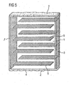
- the varistor can be designed as a multilayer varistor with integrated internal electrodes, in which case the contact bodies are preferably arranged on the side surface of the main body. Each contact body is contacted with one end of an inner electrode of an inner electrode set, see also FIG. 5 ,
- FIG. 2 is a graph of the failure rate of varistors with and without an insulating layer with mullite understanding with increasing current pulse load.
- the vertical axis represents the cumulative failure rate of the varistors in percent, while the horizontal axis represents the pulse current applied to the varistors in amperes.
- the dark bars show the behavior of varistors provided with a mullite-containing insulating layer. It can be clearly seen how the failure rates of such varistors begin to increase only at a relatively high value of 110 kA (kilo-ampere), especially when this pulse is applied in short time periods in succession. In contrast, the failure rate of varistors without an insulating layer having mullite already increases at 90 kA.
- the weight fraction of mullite is the insulating layer of the the gray bars represented Varistors is 20%. Energy varistors with a height of 44 mm and a diameter of 43.5 mm were used.
- a mullite-containing composite glaze therefore has a design optimized thermal expansion coefficient.
- the glaze also has a very good mechanical strength, which also has a positive effect on the pulse strength.
- the flexural strength at 20% by weight of mullite is 78 MPa.
- the present composite glaze advantageously also protects the ceramic due to the glassy fusion reliably against environmental influences. It is also non-toxic and harmless in the sense of environmental compatibility, since it can be composed in particular lead-free. Also, the composite glaze does not have to contain bismuth, making it much cheaper than currently used alternatives.
- the filler mullite used has a low coefficient of thermal expansion in the range of 40 * 10 -7 (K -1 ) and a high melting point at> 1800 ° C. The high melting point ensures that no or at least only a very small chemical and / or physical conversion of the filler takes place during the baking of the glaze.
- FIG. 3 shows a varistor whose surface is at least partially provided with an insulating layer 2 containing fiber composites 4.
- the fiber composites are preferably added to the previously described mullite mixture.
- the layer preferably hermetically seals an interior region of the ceramic base body to the outside.
- the envelope can withstand high loads, such as, for example, a thermally induced expansion of the ceramic base body, without it forming cracks or openings.
- the thermally induced expansion of the ceramic body can be triggered, for example, by applying an increased operating voltage, which can locally lead to melting of the varistor ceramic with explosive leakage of ceramic material and various reaction products and thus to the ignition of the varistor enclosure. As a result, this can lead to the ignition of entire devices or system parts in which the varistor is used.
- the layer containing fibers it is avoided that the possibly harmful materials emitted by the ceramic base body escape to the outside, or that the oxygen necessary for the ignition penetrates into the interior region of the ceramic base body.
- Varistorumhüllung 2 An increased strength of the Varistorumhüllung 2 is achieved with the addition of fibrous reinforcing materials of different lengths of organic and inorganic nature, as well as with the addition of organic and inorganic matrix elements or composites.
- Aramid fiber is preferred as the fiber 4 of organic nature.
- Fiber of inorganic nature is preferably glass fibers, carbon fibers or mineral wool. These have the advantage that they have a flame-retardant effect.
- Suitable organic matrix elements or composite materials are silicone resins, phenolic resins or epoxy resins.
- As inorganic Matrix elements are preferably used hydraulically setting ceramics and cements.
- Glass fiber shreds 4 having a length of 0.2 mm in different mixing ratios are preferably mixed with a silicone resin paint formulation or phenolic resin paint formulation to form a dippable or sprayable mixture which can be applied to the ceramic base body.
- the application of the envelope 2 can be carried out in multiple layers until the required coating thickness is achieved. In this case, 3 to 7, in particular 5 dives are preferred to achieve a cladding thickness of between 7 and 9 mm, as it has been found that this thickness gives a particularly good strength, but only a relatively short production time is required.
- the casing 2 enriched with the additives is brought to the desired high strength.
- a varistor 1 is shown, which is provided with contact bodies 3 at the front. It is preferred that the application of the envelope 2 takes place before the contact bodies are baked in, so that the layer applied on the front sides of the varistor is softened and subsequently pushed away or removed by the extremely high temperature during the baking of the contact body.
- the contact bodies 3 each have an outwardly directed, free surface, which can be contacted with a further contact body.
- FIG. 5 shows a multilayer varistor with a ceramic base body 1, in the interior of which internal electrodes 5 are arranged, which are each connected at one end to a contact body or metallization 3 applied to the top or side surface of the ceramic base body.
- the multilayer varistor has a mullite-containing outer layer 2 according to the preceding embodiments, which can be enriched with material-strengthening fibers.
- a multilayer varistor is provided, which can not be set on fire by means of a high-strength, preferably flame-retardant sheath 2, even with accidental or accidental overvoltages, or at least only with difficulty.
- the metallizations 3 be free of cladding materials.
Landscapes
- Engineering & Computer Science (AREA)
- Microelectronics & Electronic Packaging (AREA)
- Physics & Mathematics (AREA)
- Electromagnetism (AREA)
- Thermistors And Varistors (AREA)
Applications Claiming Priority (2)
| Application Number | Priority Date | Filing Date | Title |
|---|---|---|---|
| DE102004044648A DE102004044648A1 (de) | 2004-09-15 | 2004-09-15 | Varistor |
| PCT/DE2005/001622 WO2006029610A1 (de) | 2004-09-15 | 2005-09-15 | Varistor mit einer isolierenden schicht aus einem grundglas mit füllstoff |
Publications (2)
| Publication Number | Publication Date |
|---|---|
| EP1789977A1 EP1789977A1 (de) | 2007-05-30 |
| EP1789977B1 true EP1789977B1 (de) | 2014-08-20 |
Family
ID=35197931
Family Applications (1)
| Application Number | Title | Priority Date | Filing Date |
|---|---|---|---|
| EP05789564.1A Ceased EP1789977B1 (de) | 2004-09-15 | 2005-09-15 | Varistor mit einer isolierenden schicht aus einem grundglas mit füllstoff |
Country Status (5)
| Country | Link |
|---|---|
| US (1) | US8130071B2 (https=) |
| EP (1) | EP1789977B1 (https=) |
| JP (1) | JP4755648B2 (https=) |
| DE (1) | DE102004044648A1 (https=) |
| WO (1) | WO2006029610A1 (https=) |
Families Citing this family (5)
| Publication number | Priority date | Publication date | Assignee | Title |
|---|---|---|---|---|
| JP5272683B2 (ja) * | 2008-11-28 | 2013-08-28 | 株式会社村田製作所 | 非線形抵抗変化素子 |
| EP2507801B1 (en) | 2009-12-04 | 2014-05-21 | ABB Research Ltd. | A high voltage surge arrester |
| MX2014000493A (es) * | 2011-07-14 | 2014-05-14 | Bruce Barton | Toma portatil de corriente con supresión de sobretensión transitoria o protección contra sobretensión transitoria y método para su fabricación. |
| DE102011079813A1 (de) * | 2011-07-26 | 2013-01-31 | Siemens Aktiengesellschaft | Spannungsbegrenzende Zusammensetzung |
| WO2020018651A1 (en) | 2018-07-18 | 2020-01-23 | Avx Corporation | Varistor passivation layer and method of making the same |
Family Cites Families (23)
| Publication number | Priority date | Publication date | Assignee | Title |
|---|---|---|---|---|
| GB1346851A (en) * | 1971-05-21 | 1974-02-13 | Matsushita Electric Industrial Co Ltd | Varistors |
| DE2417523A1 (de) | 1973-05-17 | 1974-12-05 | Gen Electric | Nicht-linearer ueberspannungsableiter mit scheibenhuelse und glaszusammensetzung dafuer |
| US3959543A (en) * | 1973-05-17 | 1976-05-25 | General Electric Company | Non-linear resistance surge arrester disc collar and glass composition thereof |
| JPS5366561A (en) * | 1976-11-26 | 1978-06-14 | Matsushita Electric Industrial Co Ltd | Thick film varistor composition |
| JPS5473264A (en) | 1977-11-25 | 1979-06-12 | Tokyo Shibaura Electric Co | Nonnlinear resistor |
| JPS60219704A (ja) | 1984-04-17 | 1985-11-02 | 株式会社日立製作所 | 電圧非直線抵抗体及びその製造法 |
| US4845308A (en) * | 1987-07-20 | 1989-07-04 | The Babcock & Wilcox Company | Superconducting electrical conductor |
| JP2560851B2 (ja) | 1989-09-01 | 1996-12-04 | 富士電機株式会社 | 電圧非直線抵抗体 |
| US5294908A (en) | 1989-11-08 | 1994-03-15 | Matsushita Electric Industrial Co., Ltd. | Zinc oxide varistor, a method of preparing the same, and a crystallized glass composition for coating |
| JPH0529108A (ja) | 1991-07-23 | 1993-02-05 | Toshiba Corp | 非直線抵抗体 |
| DE4136115C1 (https=) | 1991-11-02 | 1993-01-28 | Schott Glaswerke, 6500 Mainz, De | |
| JPH0696907A (ja) | 1992-09-11 | 1994-04-08 | Murata Mfg Co Ltd | チップバリスタの製造方法 |
| FR2698736B1 (fr) * | 1992-11-27 | 1995-03-17 | Soule Sa | Perfectionnements aux parafoudres à varistances notamment pour haute tension. |
| US5294909A (en) | 1993-01-07 | 1994-03-15 | Barber-Colman Company | Resistive sensor for position detection of manifold failures |
| US5402100A (en) * | 1993-12-06 | 1995-03-28 | General Electric Company | Overvoltage surge arrester with means for protecting its porcelain housing against rupture by arc-produced shocks |
| JP3317015B2 (ja) | 1994-04-25 | 2002-08-19 | 松下電器産業株式会社 | 酸化亜鉛バリスタ |
| JPH08172002A (ja) | 1994-12-16 | 1996-07-02 | Meidensha Corp | 電圧非直線型抵抗体の製造方法 |
| US6008975A (en) * | 1997-03-03 | 1999-12-28 | Mcgraw-Edison Company | Self-compressive surge arrester module and method of making same |
| JP4157237B2 (ja) | 1998-11-09 | 2008-10-01 | 株式会社東芝 | 電圧非直線抵抗体及びその製造方法 |
| TW466507B (en) | 1999-10-04 | 2001-12-01 | Toshiba Corp | Voltage nonlinear resistor and its manufacture |
| JP2001176703A (ja) * | 1999-10-04 | 2001-06-29 | Toshiba Corp | 電圧非直線抵抗体及びその製造方法 |
| JP2002151307A (ja) | 2000-08-31 | 2002-05-24 | Toshiba Corp | 電圧非直線抵抗体 |
| JP2002305104A (ja) | 2001-04-06 | 2002-10-18 | Mitsubishi Electric Corp | 電圧非直線抵抗体およびその製造方法 |
-
2004
- 2004-09-15 DE DE102004044648A patent/DE102004044648A1/de not_active Withdrawn
-
2005
- 2005-09-15 EP EP05789564.1A patent/EP1789977B1/de not_active Ceased
- 2005-09-15 WO PCT/DE2005/001622 patent/WO2006029610A1/de not_active Ceased
- 2005-09-15 US US11/574,780 patent/US8130071B2/en not_active Expired - Fee Related
- 2005-09-15 JP JP2007531590A patent/JP4755648B2/ja not_active Expired - Fee Related
Also Published As
| Publication number | Publication date |
|---|---|
| US20080030296A1 (en) | 2008-02-07 |
| EP1789977A1 (de) | 2007-05-30 |
| JP2008513982A (ja) | 2008-05-01 |
| DE102004044648A1 (de) | 2006-03-30 |
| US8130071B2 (en) | 2012-03-06 |
| JP4755648B2 (ja) | 2011-08-24 |
| WO2006029610A1 (de) | 2006-03-23 |
Similar Documents
| Publication | Publication Date | Title |
|---|---|---|
| DE2245404C3 (de) | Massewiderstand, insbesondere für Zündkerzen, sowie Verfahren zur Herstellung desselben | |
| DE2854071A1 (de) | Zuendkerzen-isolator | |
| DE10025324A1 (de) | Bleifreie Glasur und Zündkerze | |
| DE2816358C2 (https=) | ||
| DE69021552T2 (de) | Zinkoxid-varistor, seine herstellung und zusammensetzung eines kristallisierten glases zur beschichtung. | |
| DE3501558C3 (de) | Pulvermischung zur Herstellung eines elektrischen Widerstands in einer Zündkerze | |
| DE2245403C2 (de) | Elektrisch leitende Dichtungsmasse für Zündkerzen, sowie Verfahren zur Herstellung derselben | |
| DE10049023B4 (de) | Nichtlinearer Widerstand und Verfahren zur Herstellung desselben | |
| EP1789977B1 (de) | Varistor mit einer isolierenden schicht aus einem grundglas mit füllstoff | |
| DE69632001T2 (de) | Verfahren zur Herstellung eines elektrischen Widerstandelements mit nichtlinearen spannungsabhängigen Eigenschaften | |
| DE10142314B4 (de) | Widerstand mit nichtlinearer Spannungscharakteristik (Voltage-Nonlinear-Resistor) | |
| DE10229338B4 (de) | Zündkerze und Zündkerzenisolator | |
| DE102004005664B4 (de) | Elektrisches Bauelement und Verfahren zu dessen Herstellung | |
| DE3037882A1 (de) | Nicht-linearer widerstand | |
| DE3226340C2 (https=) | ||
| DE2607454C3 (de) | Selbst spannungsabhängiger Widerstand auf der Basis von Zinkoxid | |
| DE2750002C2 (https=) | ||
| DE2361204C3 (de) | Elektrische Hochspannungseinrichtung mit Isolierkörpern | |
| EP0859377A2 (de) | Säulenförmig ausgebildeter, hochstromfester Widerstand, insbesondere Varistor auf der Basis eines Metalloxids, und Verfahren zur Herstellung eines solchen Widerstands | |
| DE2832735C2 (de) | Verfahren zur Herstellung eines stabilen Metalloxid-Varistors | |
| DE2636954B2 (de) | Spannungsabhangiger Widerstand (Varistor) und Verfahren zu seiner Herstellung | |
| DE2635699A1 (de) | Elektrischer widerstand und verfahren zur herstellung desselben | |
| DE2835562A1 (de) | Material fuer einen glasartigen elektrischen widerstand und verfahren zu dessen herstellung | |
| DE3905315A1 (de) | Elektrisch leitende glaszusammensetzung | |
| CH647897A5 (en) | Overvoltage suppressor having an internal short-circuit in the event of overloading |
Legal Events
| Date | Code | Title | Description |
|---|---|---|---|
| PUAI | Public reference made under article 153(3) epc to a published international application that has entered the european phase |
Free format text: ORIGINAL CODE: 0009012 |
|
| 17P | Request for examination filed |
Effective date: 20070213 |
|
| AK | Designated contracting states |
Kind code of ref document: A1 Designated state(s): DE FR GB |
|
| DAX | Request for extension of the european patent (deleted) | ||
| RBV | Designated contracting states (corrected) |
Designated state(s): DE FR GB |
|
| 17Q | First examination report despatched |
Effective date: 20080520 |
|
| REG | Reference to a national code |
Ref country code: DE Ref legal event code: R079 Ref document number: 502005014491 Country of ref document: DE Free format text: PREVIOUS MAIN CLASS: H01C0007120000 Ipc: H01C0007180000 |
|
| GRAP | Despatch of communication of intention to grant a patent |
Free format text: ORIGINAL CODE: EPIDOSNIGR1 |
|
| RIC1 | Information provided on ipc code assigned before grant |
Ipc: H01C 7/102 20060101ALI20140226BHEP Ipc: H01C 7/112 20060101ALI20140226BHEP Ipc: H01C 7/18 20060101AFI20140226BHEP |
|
| INTG | Intention to grant announced |
Effective date: 20140314 |
|
| GRAS | Grant fee paid |
Free format text: ORIGINAL CODE: EPIDOSNIGR3 |
|
| GRAA | (expected) grant |
Free format text: ORIGINAL CODE: 0009210 |
|
| AK | Designated contracting states |
Kind code of ref document: B1 Designated state(s): DE FR GB |
|
| REG | Reference to a national code |
Ref country code: GB Ref legal event code: FG4D Free format text: NOT ENGLISH |
|
| REG | Reference to a national code |
Ref country code: DE Ref legal event code: R096 Ref document number: 502005014491 Country of ref document: DE Effective date: 20141002 |
|
| REG | Reference to a national code |
Ref country code: DE Ref legal event code: R097 Ref document number: 502005014491 Country of ref document: DE |
|
| PLBE | No opposition filed within time limit |
Free format text: ORIGINAL CODE: 0009261 |
|
| STAA | Information on the status of an ep patent application or granted ep patent |
Free format text: STATUS: NO OPPOSITION FILED WITHIN TIME LIMIT |
|
| 26N | No opposition filed |
Effective date: 20150521 |
|
| REG | Reference to a national code |
Ref country code: FR Ref legal event code: PLFP Year of fee payment: 12 |
|
| REG | Reference to a national code |
Ref country code: FR Ref legal event code: PLFP Year of fee payment: 13 |
|
| REG | Reference to a national code |
Ref country code: FR Ref legal event code: PLFP Year of fee payment: 14 |
|
| REG | Reference to a national code |
Ref country code: DE Ref legal event code: R082 Ref document number: 502005014491 Country of ref document: DE Representative=s name: EPPING HERMANN FISCHER PATENTANWALTSGESELLSCHA, DE Ref country code: DE Ref legal event code: R081 Ref document number: 502005014491 Country of ref document: DE Owner name: TDK ELECTRONICS AG, DE Free format text: FORMER OWNER: EPCOS AG, 81669 MUENCHEN, DE |
|
| PGFP | Annual fee paid to national office [announced via postgrant information from national office to epo] |
Ref country code: FR Payment date: 20210927 Year of fee payment: 17 |
|
| PGFP | Annual fee paid to national office [announced via postgrant information from national office to epo] |
Ref country code: GB Payment date: 20210923 Year of fee payment: 17 Ref country code: DE Payment date: 20210929 Year of fee payment: 17 |
|
| REG | Reference to a national code |
Ref country code: DE Ref legal event code: R119 Ref document number: 502005014491 Country of ref document: DE |
|
| GBPC | Gb: european patent ceased through non-payment of renewal fee |
Effective date: 20220915 |
|
| PG25 | Lapsed in a contracting state [announced via postgrant information from national office to epo] |
Ref country code: FR Free format text: LAPSE BECAUSE OF NON-PAYMENT OF DUE FEES Effective date: 20220930 Ref country code: DE Free format text: LAPSE BECAUSE OF NON-PAYMENT OF DUE FEES Effective date: 20230401 |
|
| PG25 | Lapsed in a contracting state [announced via postgrant information from national office to epo] |
Ref country code: GB Free format text: LAPSE BECAUSE OF NON-PAYMENT OF DUE FEES Effective date: 20220915 |