EP1741988A1 - Méthode de rechauffement au micro-ondes et appareil - Google Patents
Méthode de rechauffement au micro-ondes et appareil Download PDFInfo
- Publication number
- EP1741988A1 EP1741988A1 EP05730531A EP05730531A EP1741988A1 EP 1741988 A1 EP1741988 A1 EP 1741988A1 EP 05730531 A EP05730531 A EP 05730531A EP 05730531 A EP05730531 A EP 05730531A EP 1741988 A1 EP1741988 A1 EP 1741988A1
- Authority
- EP
- European Patent Office
- Prior art keywords
- heating
- heated
- heating chamber
- microwave
- water
- Prior art date
- Legal status (The legal status is an assumption and is not a legal conclusion. Google has not performed a legal analysis and makes no representation as to the accuracy of the status listed.)
- Withdrawn
Links
Images


Classifications
-
- H—ELECTRICITY
- H05—ELECTRIC TECHNIQUES NOT OTHERWISE PROVIDED FOR
- H05B—ELECTRIC HEATING; ELECTRIC LIGHT SOURCES NOT OTHERWISE PROVIDED FOR; CIRCUIT ARRANGEMENTS FOR ELECTRIC LIGHT SOURCES, IN GENERAL
- H05B6/00—Heating by electric, magnetic or electromagnetic fields
- H05B6/64—Heating using microwaves
- H05B6/66—Circuits
- H05B6/68—Circuits for monitoring or control
- H05B6/687—Circuits for monitoring or control for cooking
-
- F—MECHANICAL ENGINEERING; LIGHTING; HEATING; WEAPONS; BLASTING
- F24—HEATING; RANGES; VENTILATING
- F24C—DOMESTIC STOVES OR RANGES ; DETAILS OF DOMESTIC STOVES OR RANGES, OF GENERAL APPLICATION
- F24C1/00—Stoves or ranges in which the fuel or energy supply is not restricted to solid fuel or to a type covered by a single one of the following groups F24C3/00 - F24C9/00; Stoves or ranges in which the type of fuel or energy supply is not specified
- F24C1/14—Radiation heating stoves and ranges, with additional provision for convection heating
-
- F—MECHANICAL ENGINEERING; LIGHTING; HEATING; WEAPONS; BLASTING
- F24—HEATING; RANGES; VENTILATING
- F24C—DOMESTIC STOVES OR RANGES ; DETAILS OF DOMESTIC STOVES OR RANGES, OF GENERAL APPLICATION
- F24C15/00—Details
- F24C15/32—Arrangements of ducts for hot gases, e.g. in or around baking ovens
- F24C15/322—Arrangements of ducts for hot gases, e.g. in or around baking ovens with forced circulation
- F24C15/327—Arrangements of ducts for hot gases, e.g. in or around baking ovens with forced circulation with air moisturising
-
- H—ELECTRICITY
- H05—ELECTRIC TECHNIQUES NOT OTHERWISE PROVIDED FOR
- H05B—ELECTRIC HEATING; ELECTRIC LIGHT SOURCES NOT OTHERWISE PROVIDED FOR; CIRCUIT ARRANGEMENTS FOR ELECTRIC LIGHT SOURCES, IN GENERAL
- H05B6/00—Heating by electric, magnetic or electromagnetic fields
- H05B6/64—Heating using microwaves
- H05B6/647—Aspects related to microwave heating combined with other heating techniques
- H05B6/6473—Aspects related to microwave heating combined with other heating techniques combined with convection heating
- H05B6/6479—Aspects related to microwave heating combined with other heating techniques combined with convection heating using steam
-
- H—ELECTRICITY
- H05—ELECTRIC TECHNIQUES NOT OTHERWISE PROVIDED FOR
- H05B—ELECTRIC HEATING; ELECTRIC LIGHT SOURCES NOT OTHERWISE PROVIDED FOR; CIRCUIT ARRANGEMENTS FOR ELECTRIC LIGHT SOURCES, IN GENERAL
- H05B6/00—Heating by electric, magnetic or electromagnetic fields
- H05B6/64—Heating using microwaves
- H05B6/70—Feed lines
- H05B6/704—Feed lines using microwave polarisers
-
- H—ELECTRICITY
- H05—ELECTRIC TECHNIQUES NOT OTHERWISE PROVIDED FOR
- H05B—ELECTRIC HEATING; ELECTRIC LIGHT SOURCES NOT OTHERWISE PROVIDED FOR; CIRCUIT ARRANGEMENTS FOR ELECTRIC LIGHT SOURCES, IN GENERAL
- H05B6/00—Heating by electric, magnetic or electromagnetic fields
- H05B6/64—Heating using microwaves
- H05B6/74—Mode transformers or mode stirrers
Definitions
- the present invention relates to microwave heating method and apparatus for dielectrically heating an object to be heated.
- microwaves radiated from a magnetron are transmitted through a waveguide to a heating chamber to form standing waves within the heating chamber, and an object to be heated is caused to generate heat according to the electric field component of the standing waves and the dielectric loss of the object to be heated.
- the size of the heating chamber for storing therein the object to be heated is generally as follows: that is, the width and depth dimensions thereof are respectively 30 - 40 cm, and the height dimension thereof is about 20 cm.
- the wavelength of a microwave used is about 12 cm and thus the microwave resonates within the heating chamber to thereby provide a standing wave, with the result that there are always generated high- and low-intensity electric field distributions; and further, the shape and physical properties of the object to be heated can cooperate together synergistically to thereby generate heat locally.
- the microwave oven in the thawing treatment of the current microwave oven, by decreasing the output of the microwave intentionally or by setting the time not to apply the microwave during heating, the microwave oven is allowed to wait for realization of the averaged temperature due to the heat transfer in the interior of the food, thereby enhancing the cooked result of the food.
- the object to be heated is humidified or heated by applying mist or steam to the object to be heated, for an object to be steamed such as a Chinese meat-bun and a shao-mai or for a food to be just warmed up or heated up, there may be obtained a good result, but, when a frozen food is thawed, there cannot be restricted the local heating phenomenon. Therefore, as for the thawing purpose, the conventional cooking apparatus cannot make the most of the advantage in supplying water particles.
- the present invention is made to solve the problems found in the conventional cooking apparatus.
- the microwave heating method when a given temperature difference has been generated, the minute particles of water are supplied into the heating chamber to change the permittivity distribution condition within the heating chamber, thereby changing the distribution of electric fields due to the microwaves supplied into the heating chamber. Thanks to this, the local heating peculiar to the microwave heating can be restricted, the heating of the object to be heated can be made uniform, and the heated result of the object to be heated can be enhanced.
- the present microwave heating method since the electric field distribution is varied finely, the local heating can be restricted and thus the effect of heating the object to be heated uniformly can be enhanced.
- microwave heating method owing to use of steam as the minute particles of water, heat transfer by steam and the change of the permittivity of the interior of the heating chamber can be carried out at the same time, which can enhance the efficiency of the heating of the object to be heated.
- the present microwave heating method owing to use of mist-like water drops as the minute particles of water, quick supply of water is possible, which can enhance the response of the electric field control.
- the microwave heating method after the object to be heated is microwave heated in a first state in which two or more high-intensity electric fields are present within the heating chamber, the minute particles of water are supplied into the heating chamber to change the permittivity distribution state of the interior of the heating chamber to thereby increase the number of the high-intensity electric fields over the first state. Thanks to this, the high-intensity electric fields can be generated not partially only in the specific positions of the object to be heated but uniformly over the entire areas thereof, thereby being able to enhance the uniform heating of the object to be heated.
- the present microwave heating method since the state of the electric fields is changed when a given temperature difference is generated in the temperature distribution of the object to be heated, the temperature difference can be reduced and thus the temperature distribution can be made uniform.
- the present microwave heating apparatus while supplying microwaves from the microwave generating part to the heating chamber, the temperature distribution of the interior of the heating chamber is measured using the temperature measuring means and the minute particles of water are supplied into the heating chamber at a given timing, thereby changing the distribution of electric fields provided by the microwaves supplied into the heating chamber. Thanks to this, the local heating peculiar to the microwave heating can be restricted, the uniform heating of the object to be heated can be realized, and the cooked state of the object to be heated after heated can be enhanced.
- the present microwave heating apparatus by supplying a given amount of water from the water tank to the evaporation dish using the water pump and heating the evaporation dish using the evaporation dish heating means, a desired amount of steam can be generated. Also, since the evaporation dish is disposed within the heating chamber, it is easy to clean the heating chamber and thus the interior of the heating chamber can be kept sanitary.
- the distribution of the high-intensity electric fields can be changed quickly.
- the permittivity changing means there are respectively generated the first permittivity distribution state for heating the evaporation dish after supply of the water to the evaporation dish to thereby generate steam as well as the second permittivity distribution state for supplying the water after heating of the evaporation dish to thereby generate steam immediately, and these first and second states are controlled using the heating control means, whereby the electric field distribution state of the interior of the heating chamber can be changed and thus the object to be heated can be heated uniformly.
- the minute particles of water are supplied into the heating chamber to change the permittivity distribution state of the interior of the heating chamber, thereby changing the electric field distribution of the interior of the heating chamber provided by microwaves supplied into the heating chamber. Thanks to this, the local heating peculiar to the microwave heating can be restrained and thus the heating of the object to be heated can be made uniform, resulting in the enhanced finished state of the object to be heated after heated.
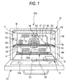
- Fig. 1 is a front view of a microwave heating apparatus according to the invention, showing a state in which an opening and shutting door is opened
- Fig. 2 is an explanatory view of the basic operation of the microwave heating apparatus
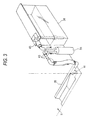
- Fig. 3 is an explanatory view of a water supply passage to a steam supply part
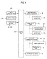
- Fig. 4 is a block diagram of a control system for controlling the microwave heating apparatus.
- This microwave heating apparatus (which is hereinafter referred to as a cooking apparatus) 100 is a cooking apparatus which, as shown in Fig. 1, supplies at least one of microwaves and steam S to a heating chamber 11 storing therein an object to be heated to heat treat the object to be heated.
- the cooking apparatus 100 comprises a magnetron 13 serving as a microwave generating portion 12 for generating microwaves, a steam supply part 15 which generates steam S within the heating chamber 11 and functions as permittivity changing means, an upper heating heater 16 disposed upwardly of the heating chamber 11, a circulation fan 17 for stirring up and circulating the air existing within the heating chamber 11, and a convection heater 19 for heating the air circulating within the heating chamber 11.
- the cooking apparatus 100 further includes an infrared sensor 18 functioning as temperature measuring means for measuring the temperature of the object to be heated within the heating chamber 11 through a detecting hole formed in the wall surface of the heating chamber 11, a thermistor 20 disposed on the wall surface of the heating chamber 11 for measuring the temperature of the heating chamber 11, and a tray 22 functioning as a partition plate removably disposed upwardly of the bottom surface of the heating chamber 11 with a given clearance between them for dividing the heating chamber 11 vertically into upper and lower section spaces.
- an infrared sensor 18 functioning as temperature measuring means for measuring the temperature of the object to be heated within the heating chamber 11 through a detecting hole formed in the wall surface of the heating chamber 11, a thermistor 20 disposed on the wall surface of the heating chamber 11 for measuring the temperature of the heating chamber 11, and a tray 22 functioning as a partition plate removably disposed upwardly of the bottom surface of the heating chamber 11 with a given clearance between them for dividing the heating chamber 11 vertically into upper and lower section spaces.
- the heating chamber 11 is formed in the interior of a box-shaped main body case 10 with its front surface opened.
- the lower end of the opening and shutting door 21 is hinge connected to the lower edge of the main body case 10, whereby the opening and shutting door 21 can be opened and shut in the vertical direction.
- the magnetron 13 is disposed, for example, in the lower section space of the heating chamber 11 and, at a position where microwaves generated from the magnetron 13 are received, there is provided a stirrer blade 33 (or a rotary antenna or the like) serving as radio wave stirring means. And, by radiating the microwaves from the magnetron 13 onto the rotating stirrer blade 33, the microwaves can be supplied into the heating chamber 11 by the stirrer blade 33 while the microwaves are being stirred up by the stirrer blade 33.
- the mounting portions of the magnetron 13 and stirrer blade 33 are not limited to the bottom portion of the heating chamber 11, but they may also be mounted on the upper surface or side surfaces of the heating chamber 11.
- the rear wall surface of the heating chamber 11 provides a deep side wall surface 27 which separates the heating chamber 11 and circulation fan chamber 25 from each other.
- the deep side wall surface 27 there are formed air intake ventilation holes 29 for sucking the air from the heating chamber 11 side to the circulation fan chamber 25 side, and air feed ventilation holes 31 for supplying the air from the circulation fan chamber 25 side to the heating chamber 11 side, while the respective formation areas of the air intake ventilation holes 29 and the air feed ventilation holes 31 are separated from each other (see Fig. 1).
- the respective ventilation holes 29 and 31 are formed in the form of a large number of punched holes.
- a hot wind generating portion 14 is composed of the circulation fan 17 and convection heater 19.
- the circulation fan chamber 25 there is provided the rectangular-ring-shaped convection heater 19 in such a manner that it surrounds the circulation fan 17.
- the air intake ventilation holes 29 are arranged in front of the circulation fan 17, while the air feed ventilation holes 31 are arranged at positions along the rectangular-ring-shaped convection heater 19. Therefore, when the circulation fan 17 is driven and rotated, the air existing in the interior of the heating chamber 11 is sucked through the air intake ventilation holes 29 into the central position of the convection heater 19 where the circulation fan 17 exists and is diffused radially there; and the air passes through the neighborhood of the convection heater 19 and is thereby heated, and is then charged through the air feed ventilation holes 31 into the heating chamber 11. That is, the air provides a circulation wind.
- the steam supply part 15 comprises an evaporation dish 35 including a pool recessed portion 35a for generating steam S by heating, and an evaporation dish heating heater 37 disposed downwardly of the evaporation dish 35 for heating the evaporation dish 35.
- the evaporation dish 35 is composed of, for example, a stainless-steel made plate member which includes a recessed portion and has a narrow and long shape.
- the evaporation dish 35 is disposed on the deep side bottom surface of the heating chamber 11 on the opposite side of the object-to-be-heated take-out mouth, while the longitudinal direction of the evaporation dish 35 extends along the deep side wall surface 27.
- the evaporation dish heating heater 37 although not shown, there is employed a heater having a structure in which an aluminum die cast heat block with a heat generating element such as a sheath heater is in contact with the evaporation dish 35.
- the evaporation dish 35 may be heated with radiant heat using a glass tube heater or a sheath heater.
- a plate heater or the like is bonded to the evaporation dish 35.
- a water tank 38 for storing therein water which is to be supplied to the evaporation dish 35
- a water pump 39 for feeding the water stored in the water tank 38
- a water supply pipe line 43 the discharge port 41 of which is disposed opposed to the evaporation dish 35.
- Water, which is stored in the water tank 38, as the need arises, can be supplied by a desired amount through the water supply pipe line 43 to the evaporation dish 35.
- the water tank 38 is buried in a compact manner into the side wall portion of the main body case 10 that is relatively hard to become high in temperature.
- the upper heating heater 16 is a plate heater such as a mica heater which applies heat for grill cooking or preheats the heating chamber 11; and, the upper heating heater 16 is disposed upwardly of the heating chamber 11. Also, the upper heating heater 16 may also be composed of a sheath heater instead of the plate heater.
- the thermistor 20 is disposed on the wall surface of the heating chamber 11 and is used to detect the temperature of the interior of the heating chamber 11.
- the infrared sensor 18 On the wall surface of the heating chamber 11, there is further provided the infrared sensor 18 in a freely oscillatable manner which can measure the temperatures of two or more points (for example, 8 points) at the same time. Using a scanning operation which can be carried out by oscillating the infrared sensor 18, the temperatures of two or more measuring points within the heating chamber 11 can be measured and further, to monitor the temperatures of the measuring points with the passage of time can tell the position of placement of the object to be heated M.
- the tray 22 is removably supported on securing portions 26 which are respectively provided on the side surfaces 11a and 11b of the heating chamber 11.
- the securing portions 26 are arranged in two or more stages in such a manner that they can support the tray 22 at two or more height positions.
- the heating chamber 11 can be divided into an upper section space 11A and a lower section space 11B.
- Fig. 4 is a block diagram of a control system employed in the cooking apparatus 100 and this control system is mainly composed of a control part 51 including, for example, a microprocessor.
- the control part 51 mainly transmits and receives signals with respect to an input operation part 53, a display panel 55, the microwave generating portion 12, the steam supply part 15, the hot wind generating portion 14, the upper heating heater 16, temperature sensors 18, 20 and the like; and, the control part 51 controls these respective portions.
- the input operation part 53 includes various kinds of keys such as a start key, a switching key for switching heating methods, and an automatic cooking key; and, cooking is carried out by operating the keys properly according to the heating contents while confirming the temperatures displayed on the display panel 55.
- keys such as a start key, a switching key for switching heating methods, and an automatic cooking key; and, cooking is carried out by operating the keys properly according to the heating contents while confirming the temperatures displayed on the display panel 55.
- a food which is the object to be heated M
- a dish or the like is inserted into the heating chamber 11, and, after then, the opening and shutting door 21 is shut.
- a cooking method, a heating time, a heating temperature and the like are set and, after then, when a start button is depressed, the cooking is carried out automatically according to the operation of the control part 51.
- a mode "steam generation + circulation fan ON" is selected, since the evaporation dish heating heater 37 is switched on, water in the evaporation dish 35 is heated to thereby generate the steam S. Since the steam S rising from the evaporation dish 35 is allowed to circulate through the heating chamber 11, the steam S can be uniformly blown onto the object to be heated M.
- the temperature of the steam S circulating through the heating chamber 11 can be set at a further higher temperature. Therefore, there can be obtained so called overheated steam, which makes it possible to cook the object to be heated M in such a manner that it has a browned surface.
- the magnetron 13 may be turned on to rotate the stirrer blade 33, so that the microwaves can be supplied into the heating chamber 11 while they are being stirred up uniformly, thereby being able to microwave cook the object to be heated M evenly.
- the object to be heated (food) M can be heated according to the heating method that is best for cooking.
- the control part 51 controls the magnetron 13, upper heating heater 16, convection heater 19 and the like properly.
- the cooking apparatus 100 further has a function to control cooking using microwaves.
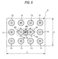
- Fig. 5 is a plan view of the bottom surface of the heating chamber when it is viewed from above.
- ferromagnetic fields 63, 65 which are designated by broken-line arrow marks respectively
- ferromagnetic fields 63, 65 which are designated by broken-line arrow marks respectively
- the microwaves when the microwaves enter the heating chamber 11, the microwaves resonate with the ferromagnetic fields within the heating chamber 11.
- a magnetic field and an electric field are 90 degrees out of phase with each other, whereby there are generated high-intensity electric fields 67, 69 (which are shown by solid-line arrow marks) which are out of phase with the ferromagnetic fields 63, 65 in such a manner that they hold the radio wave opening 60 between them.
- the resonating state, when the object to be heated is absent, is decided by the shape of the heating chamber and the position of the radio wave opening.
- the high-intensity electric fields 67, 69 out of phase with the ferromagnetic fields 63, 65 stand perpendicularly to the bottom surface of the heating chamber 11 and, at the same time, high-intensity electric fields 71 stand in the same direction (in Fig. 5, in the far side direction) as the high-intensity electric field 67 and high-intensity electric fields 73 stand in the same direction (in Fig. 5, in the near side direction) as the high-intensity electric field 69.
- slanting line portions in Fig. 5 express areas where, of the electric fields that are generated on the bottom surface of the heating chamber 11, the electric fields the intensity of which is higher than a certain level exist; and, there are generated three high-intensity electric fields in the deep side direction (x direction) of the heating chamber, and four high-intensity electric fields in the width direction thereof (y direction).
- the reason for this is that, owing to the generation of the resonating state, electromagnetic waves are distributed as standing waves within the heating chamber to thereby cause the antinodes of the electric fields; and, the number of these antinodes is called a mode.
- Slanting line portions in Fig. 6 express areas where, of the electric fields that are generated on the wall surfaces of the heating chamber 11, there exist the electric fields the intensity of which is higher than a given level, while the mutually facing wall surfaces of the heating chamber show electric field distributions which are symmetric.
- a standable mode can be found analytically.
- the dimensions of the heating chamber 11 are x, y and z
- the number of modes standing in the respective directions is the number of combinations of r, s and t which satisfy the following equation (1).
- x, y and z are expressed in a unit of mm; r, s and t are integers; and ⁇ is the wavelength of a microwave and it is about 122 mm).
- the permittivity ⁇ provides 1 for the air and about 3 for steam. That is, by supplying steam from the steam supply part 15 into the heating chamber 11, the permittivity of the interior of the heating chamber 11 is changed, whereby the wavelength of the microwave is shifted to the short wavelength side according to the relation of the equation (2). As a result of this, the mode of the high-intensity electric fields to be decided according to the equation (1) is changed.
- Fig. 7 is a view of the variations of the high intensity electric fields occurring on the wall surfaces of the heating chamber. Assuming that the high-intensity electric fields 75 shown in Fig. 7 are present at the positions of the high-intensity electric fields on the bottom surface of the heating chamber, Fig.
- Fig. 8 is an explanatory view to explain conceptually the states of a microwave respectively in a case shown in Fig. 8A when the water minute particles are not supplied into the heating chamber 11 and in a case shown in Fig. 8B when the water minute particles are supplied.
- the microwave heating is carried out while the wavelength of the microwave is about 122mm.
- the permittivity of the interior of the heating chamber 11 increases and thus the wavelength of the microwave is shortened.
- the distribution of standing waves caused by the microwaves within the heating chamber 11 becomes fine, so that there can be obtained the effect of uniformly heating the object to be heated.
- the shortened wavelength of the microwave decreases the penetration depth of the microwave into the object to be heated, whereby the surface of the object to be heated can be heated particularly.
- Fig. 9 is a graphical representation of an example of the sequence of microwave heating and steam supply in the thawing processing of a frozen food.
- the output of microwaves generated from the microwave generating portion 12 is turned on continuously for the first given time (for example, two minutes).
- the temperature distribution of the interior of the heating chamber 11 is also measured using the infrared sensor 18.
- Fig. 10A while the infrared sensor 18 is detecting the temperatures of two or more points (n points) simultaneously, the infrared sensor 18 itself is oscillated, whereby the infrared sensor 18 scans the interior of the heating chamber 11 in the arrow mark direction in Fig. 10A and measures the temperatures of two or more measuring points (m points in the scanning direction) of the interior of the heating chamber 11. Therefore, the scanning operation of the infrared sensor 18 detects the temperatures of all measuring points, that is, n x m points shown in Fig. 10B.
- the placement position of the object to be heated M is found based on the rising rates of the temperatures of the respective measuring points continuously detected with respect to the passage of time, and the thus detected temperature at the placement position is regarded as the temperature of the object to be heated M.
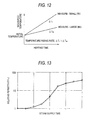
- Fig. 11 shows the temperature distribution at the L line position shown in Fig. 10B when the scanning operations by the infrared sensor 18 are carried out two or more times successively.
- the peak position (trough position) of the temperature distribution in which the temperature varies specifically within one scan width, corresponds to the position of the object to be heated M on the L line in Fig. 10B. Therefore, the position of the object to be heated M within the heating chamber 11 can be found from the peak existing position of the temperature distribution.
- the initial temperature of the object to be heated M can be judged.
- the measure of the object to be heated M can be estimated.
- the reason for this is as follows: that is, as shown in Fig.
- the temperature rising rates ⁇ t of the objects to be heated M1 and M2 differ from each other according to the weights thereof; and, when the object to be heated M1 having small measure is heated, the temperature rising rate thereof provides ⁇ TL and, when the object to be heated M2 having large measure is heated, the temperature rising rate thereof provides ⁇ TM smaller than ⁇ TL. Accordingly, by estimating the measure of the object to be heated M from the above-mentioned judgment of the initial temperature of the object to be heated M and temperature rising rate ⁇ T, the thawing processing end time of the frozen food can be set.
- Fig. 14 which conceptually shows the heating condition of the object to be heated
- the interior Min of the object to be heated is heated especially strongly as shown in Fig. 14A
- the mode is turned into a mode in which high-intensity electric fields are distributed finely, and thus, as shown in Fig. 14B, the surface Mout of the object to be heated is heated especially strongly; and, finally, as shown in Fig. 14C, the cooking of the object to be heated is finished in such a manner that the interior Min and surface Mout thereof are heated uniformly.
- the output of the microwave heating is caused to stop.
- the object to be heated in a first state where, of high- and low-intensity electric fields (antinodes and nodes) obtained by supplying microwaves to the heating chamber 11, two or more high-intensity electric fields (antinodes) are present within the heating chamber 11, the object to be heated is heated using microwaves; and, after then, the water minute particles are supplied from the steam supply part 15 into the heating chamber 11 to thereby change the permittivity distribution state of the interior of the heating chamber 11 into a second state where the number of high-intensity electric fields (antinodes) is increased over the first state, and, in this second state, the object to be heated is heated using microwaves. That is, the object to be heated is microwave heated in two different states. This can restrain the local microwave heating from having an influence on the finally cooked condition of the object to be heated, thereby being able to finish the object to be heated in a good condition with no uneven heating.
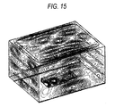
- Fig. 15 shows a case in which the permittivity of the interior of the heating chamber is set for 1 equivalent to the air
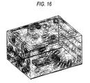
- Fig. 16 shows a case in which the permittivity of the whole of the heating chamber is set for 3 equivalent to steam.
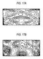
- Fig. 17 is a diagram of the equal electric field intensity of the interior of the object to be heated obtained by a CAE analysis.
- Fig. 17A shows a case in which the permittivity of the interior of the heating chamber is set for 1 equivalent to the air
- Fig. 17B shows a case in which the permittivity of the whole of the heating chamber is set for 3 equivalent to the steam.
- the distributions of high-intensity electric fields are obviously different.
- the distribution of high-intensity electric fields in the case shown in Fig. 17B where the object to be heated is heated by the microwave heating with supply of the steam is finer than that of the case shown in Fig. 17A where the object to be heated is heated only by the microwave heating without supply of the steam.
- the object of the invention to supply steam into the heating chamber is, as shown in Fig. 19 which is modeled on high-intensity electric fields within the object to be heated, to make finer the distribution of high-intensity electric fields shown in Fig. 19B where the object to be heated is heated by microwaves with supply of steam than the distribution of high-intensity electric fields shown in Fig. 19A where the object to be heated is heated simply by microwaves.
- the heating points positions of generation of the high-intensity electric fields
- the subdivision effect cooperates together with the above-mentioned uniform heating effect due to supply of steam in realizing the further uniform heating of the object to be heated.
- the steam supply part 15 supplies the water minute particles, which are dielectric substances, into the heat chamber 11 arbitrarily to change the permittivity of the interior of the heating chamber 11.
- supply of water into the evaporation dish 35 can also change the permittivity of the interior of the heating chamber 11.
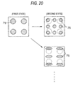
- a microwave heating method when changing the high-intensity electric fields of microwaves within the heating chamber 11, the mode of high-intensity electric fields is arranged in such a manner that, in the above-mentioned first state before supply of steam and second state after supply of steam, the high-intensity electric fields are allowed to occur at mutually different positions as much as possible.
- Fig. 20 is an explanatory view of the positions of the high-intensity electric fields in the first and second states. As shown in Fig.
- the high-intensity electric fields are generated so as to contain positions to be complemented in order that the high-intensity electric fields 75 can be generated at positions where the high-intensity electric fields 75 have not been generated in the first state.
- the amount of steam to be supplied into the heating chamber 11 may be adjusted to thereby set the permittivity of the interior of the heating chamber 11 that can produce a desired mode, or the direction of the stirrer blade 33 may be changed.
- This position control of the high-intensity electric fields makes it possible to microwave heat the object to be heated further uniformly, resulting in the further better result after heated.
- Fig. 21 shows a schematic structure view of a microwave heating apparatus according to the second embodiment of the invention.
- the steam supply part 15 is structured such that it guides steam generated in the evaporation dish 35 out of the heating chamber 11 once and blows the steam from above the heating chamber 11 through an external pipe 81 into the heating chamber 11 again.
- a tray 83 made of ceramics, resin, glass or the like which transmits microwaves, while a space within the heating chamber 11 is vertically divided by the tray 83 into upper and lower section spaces.
- the steam generating means is not limited to a power heating type of steam generating means for heating the evaporation dish 35 including a structure according to the first embodiment but, for example, there may also be used a boiler type of steam generating means.
- a structure in which the evaporation dish 35 is disposed within the heating chamber 11 in an exposed manner it is easy to remove scales which stick to the evaporation dish 35 when steam is generated; and, therefore, this structure is excellently sanitary.
- a drop type structure in which a valve of a water supply passage is opened to drop water drops down to a heating member to thereby generate steam.
- a similar effect to the case of the evaporation dish 35.
- the distribution of electric fields can be changed. For example, a first permittivity distribution state in which, after water is supplied to the evaporation dish 35, the evaporation dish 35 is heated to thereby generate steam and a second permittivity distribution state in which, after the evaporation dish 35 is heated, water is supplied to the evaporation dish 35 to thereby generate steam immediately may be generated independently or simultaneously, with the result that the electric field distribution can be changed.
- Fig. 22 shows a schematic structure view of a microwave heating apparatus according to the third embodiment of the invention.
- the steam supply part 15 is structured such that, instead of use of steam obtained by heating water, it includes mist supply means 87 for supplying mist-like water drops into the heating chamber 11.
- mist-like water drops of a minute size are supplied into the heating chamber 11. It is considered that the larger the size of the mist is, the greater the effect of changing the electric field distribution of a microwave is.
- the size of the mist may be set larger than the ordinary size of the mist, 3 ⁇ m, preferably, it may be set for 10 ⁇ m or larger, more preferably, in the range of 25 ⁇ m - 100 ⁇ m, with the result that the sufficient action of the mist on the microwave can be secured, thereby being able to cause the electric field distribution to change positively.
- the mist supply means 87 generally, there is often used an ultrasonic vibrator of 1.6 - 2.4 MHz.
- an ultrasonic spray including an ultrasonic vibrator which can be vibrated at 20kHz - 100kHz; and also, there can be used, for example, a high pressure spray and a spray of a centrifugal type or other types.
- the heating chamber 11 is vertically divided into upper and lower section spaces by the tray 83, and the mist is supplied only to the upper section space 11A.
- the mists are supplied to the upper section space 11A of the heating chamber 11 and only the upper section space 11A is filled with the mists. Therefore, similarly to the second embodiment, the microwave acts in such a manner that a space where the microwave is supplied is changed in shape, which makes it possible to change the distribution of high-intensity electric fields. This can change the effect of heating onto the object to be heated, thereby being able to facilitate the uniform heating of the object to be heated.
Landscapes
- Engineering & Computer Science (AREA)
- Physics & Mathematics (AREA)
- Electromagnetism (AREA)
- Chemical & Material Sciences (AREA)
- Combustion & Propulsion (AREA)
- Mechanical Engineering (AREA)
- General Engineering & Computer Science (AREA)
- Power Engineering (AREA)
- Electric Ovens (AREA)
- Constitution Of High-Frequency Heating (AREA)
- Control Of High-Frequency Heating Circuits (AREA)
Applications Claiming Priority (2)
| Application Number | Priority Date | Filing Date | Title |
|---|---|---|---|
| JP2004132648A JP2005315487A (ja) | 2004-04-28 | 2004-04-28 | マイクロ波加熱方法及びその装置 |
| PCT/JP2005/007242 WO2005106333A1 (fr) | 2004-04-28 | 2005-04-14 | Méthode de rechauffement au micro-ondes et appareil |
Publications (2)
| Publication Number | Publication Date |
|---|---|
| EP1741988A1 true EP1741988A1 (fr) | 2007-01-10 |
| EP1741988A4 EP1741988A4 (fr) | 2007-10-03 |
Family
ID=35241758
Family Applications (1)
| Application Number | Title | Priority Date | Filing Date |
|---|---|---|---|
| EP05730531A Withdrawn EP1741988A4 (fr) | 2004-04-28 | 2005-04-14 | Méthode de rechauffement au micro-ondes et appareil |
Country Status (5)
| Country | Link |
|---|---|
| US (1) | US20070215608A1 (fr) |
| EP (1) | EP1741988A4 (fr) |
| JP (1) | JP2005315487A (fr) |
| CN (1) | CN1950645A (fr) |
| WO (1) | WO2005106333A1 (fr) |
Cited By (5)
| Publication number | Priority date | Publication date | Assignee | Title |
|---|---|---|---|---|
| EP2446706B1 (fr) | 2010-05-03 | 2016-01-27 | Goji Limited | Analyse modale |
| EP2916619B1 (fr) | 2010-05-03 | 2016-12-14 | Goji Limited | Analyse modale |
| EP1995525B1 (fr) * | 2007-05-25 | 2017-03-01 | Whirlpool EMEA S.p.A | Four de cuisson |
| WO2020156928A1 (fr) * | 2019-02-01 | 2020-08-06 | BSH Hausgeräte GmbH | Appareil domestique de cuisson et procédé pour faire fonctionner un appareil domestique de cuisson |
| WO2022128311A1 (fr) * | 2020-12-16 | 2022-06-23 | BSH Hausgeräte GmbH | Système constitué d'un dispositif de cuisson et d'un récipient d'évaporation passive d'eau |
Families Citing this family (32)
| Publication number | Priority date | Publication date | Assignee | Title |
|---|---|---|---|---|
| CA2296632A1 (fr) | 1997-07-16 | 1999-01-28 | Impulse Dynamics (Israel) Ltd. | Module de commande de muscle lisse |
| JP2006066137A (ja) * | 2004-08-25 | 2006-03-09 | Matsushita Electric Ind Co Ltd | マイクロ波加熱装置 |
| US10674570B2 (en) | 2006-02-21 | 2020-06-02 | Goji Limited | System and method for applying electromagnetic energy |
| EP2528414B1 (fr) | 2006-02-21 | 2016-05-11 | Goji Limited | Chauffage électromagnétique |
| US8839527B2 (en) | 2006-02-21 | 2014-09-23 | Goji Limited | Drying apparatus and methods and accessories for use therewith |
| US8653482B2 (en) | 2006-02-21 | 2014-02-18 | Goji Limited | RF controlled freezing |
| EP2127481A1 (fr) | 2007-02-21 | 2009-12-02 | RF Dynamics Ltd. | Congélation commandée par rf |
| IL184672A (en) | 2007-07-17 | 2012-10-31 | Eran Ben-Shmuel | Apparatus and method for concentrating electromagnetic energy on a remotely-located object |
| US9131543B2 (en) | 2007-08-30 | 2015-09-08 | Goji Limited | Dynamic impedance matching in RF resonator cavity |
| KR101185557B1 (ko) * | 2007-10-09 | 2012-09-24 | 삼성전자주식회사 | 조리기기 및 그 제어방법 |
| JP5131969B2 (ja) * | 2007-12-19 | 2013-01-30 | パナソニック株式会社 | 加熱調理器 |
| EP3048862B1 (fr) | 2008-11-10 | 2019-10-16 | Goji Limited | Dispositif et procédé de contrôle d'énergie |
| DE102009005358A1 (de) * | 2009-01-16 | 2010-07-22 | Krones Ag | Resonatoreinheit, Expansionsverfahren und Vorrichtung zur Erwärmung von Behältnissen |
| CN102003996A (zh) * | 2009-08-29 | 2011-04-06 | 乐金电子(天津)电器有限公司 | 鉴别微波炉上食物的形状、大小、摆放位置及温度的方法 |
| US20120160844A1 (en) * | 2009-09-07 | 2012-06-28 | Panasonic Corporation | Microwave heating device |
| DE102009029254A1 (de) * | 2009-09-08 | 2011-03-24 | BSH Bosch und Siemens Hausgeräte GmbH | Mikrowellen-Gargerät mit Sprühvorrichtung und Verfahren zum Betreiben eines Mikrowellen-Gargeräts mit Sprühnebel |
| JP5588989B2 (ja) | 2009-09-16 | 2014-09-10 | パナソニック株式会社 | マイクロ波加熱装置 |
| WO2011092710A2 (fr) | 2010-02-01 | 2011-08-04 | Metacure Limited | Thérapie électrique gastro-intestinale |
| US9538880B2 (en) * | 2012-05-09 | 2017-01-10 | Convotherm Elektrogeraete Gmbh | Optical quality control system |
| JP2014116175A (ja) * | 2012-12-10 | 2014-06-26 | Panasonic Corp | マイクロ波加熱装置 |
| CN103994480B (zh) * | 2013-02-18 | 2016-11-16 | 广东美的厨房电器制造有限公司 | 微波炉 |
| CN105325055A (zh) * | 2013-06-28 | 2016-02-10 | 皇家飞利浦有限公司 | 用于处理冷冻食物的方法和设备 |
| US9194625B2 (en) | 2013-08-20 | 2015-11-24 | Whirlpool Corporation | Method for drying articles |
| JP6586274B2 (ja) * | 2014-01-24 | 2019-10-02 | パナソニック インテレクチュアル プロパティ コーポレーション オブ アメリカPanasonic Intellectual Property Corporation of America | 調理装置、調理方法、調理制御プログラム、および、調理情報提供方法 |
| CN105940267B (zh) * | 2014-02-05 | 2018-04-24 | 松下知识产权经营株式会社 | 加热烹调器 |
| KR102336430B1 (ko) | 2015-10-21 | 2021-12-08 | 삼성전자주식회사 | 저주파 자기장 기반 가열 장치 및 방법 |
| JP6887077B2 (ja) * | 2016-03-25 | 2021-06-16 | パナソニックIpマネジメント株式会社 | マイクロ波加熱装置 |
| DE102016215650A1 (de) * | 2016-08-19 | 2018-02-22 | BSH Hausgeräte GmbH | Haushaltsgargerät |
| CN108235483B (zh) * | 2018-01-16 | 2020-10-27 | 昆明理工大学 | 一种等效介电常数能够调节的微波加热装置及方法 |
| CN110730523B (zh) * | 2019-09-29 | 2024-04-19 | 郑州诺科精密科技有限公司 | 一种快速解冻加热系统及方法 |
| JP2021196100A (ja) * | 2020-06-12 | 2021-12-27 | 日立グローバルライフソリューションズ株式会社 | 加熱調理器 |
| CN114007295B (zh) * | 2021-11-19 | 2022-05-24 | 成都大学 | 一种微波加热装置的控制方法、装置及存储介质 |
Citations (6)
| Publication number | Priority date | Publication date | Assignee | Title |
|---|---|---|---|---|
| JPH06272866A (ja) * | 1993-03-16 | 1994-09-27 | Fuji Mc:Kk | 複合型加熱装置 |
| EP0952400A1 (fr) * | 1996-09-03 | 1999-10-27 | Matsushita Electric Industrial Co., Ltd. | Dispositif de chauffage par micro-ondes |
| US6008482A (en) * | 1994-10-24 | 1999-12-28 | Matsushita Electric Industrial Co., Ltd. | Microwave oven with induction steam generating apparatus |
| US6133558A (en) * | 1996-06-24 | 2000-10-17 | Matsushita Electric Industrial Co., Ltd. | Microwave steam heater with microwave and steam generators controlled to equalize workpiece inner and surface temperatures |
| US6646241B1 (en) * | 2002-02-08 | 2003-11-11 | Ecofriend Technologies, Inc. | Microwave-assisted steam sterilization of dental and surgical instruments |
| EP1372358A1 (fr) * | 2002-06-14 | 2003-12-17 | Matsushita Electric Industrial Co., Ltd. | Appareil chauffant à haute fréquence avec fonction de génération de vapeur |
Family Cites Families (20)
| Publication number | Priority date | Publication date | Assignee | Title |
|---|---|---|---|---|
| JPS6026243Y2 (ja) * | 1979-02-14 | 1985-08-07 | 松下電器産業株式会社 | 高周波加熱装置 |
| JP3102235B2 (ja) * | 1993-11-15 | 2000-10-23 | 松下電器産業株式会社 | 高周波加熱装置 |
| JP3103745B2 (ja) * | 1995-05-24 | 2000-10-30 | 松下電器産業株式会社 | 高周波加熱装置 |
| JP3477919B2 (ja) * | 1995-06-22 | 2003-12-10 | 松下電器産業株式会社 | 蒸気とマイクロ波による食品加熱調理方法 |
| JP3553742B2 (ja) * | 1996-09-03 | 2004-08-11 | 松下電器産業株式会社 | マイクロ波加熱装置 |
| JP3284263B2 (ja) * | 1996-10-07 | 2002-05-20 | シャープ株式会社 | マイクロ波加熱装置 |
| JPH10325544A (ja) * | 1997-05-28 | 1998-12-08 | Nitto Reinetsu Seisakusho:Kk | 蒸気加熱装置 |
| JP3932638B2 (ja) * | 1998-01-19 | 2007-06-20 | 松下電器産業株式会社 | 加熱調理器 |
| JP3317227B2 (ja) * | 1998-01-27 | 2002-08-26 | 松下電器産業株式会社 | 高周波加熱装置 |
| JPH11354267A (ja) * | 1998-06-10 | 1999-12-24 | Matsushita Electric Ind Co Ltd | 高周波加熱装置 |
| JP4465821B2 (ja) * | 2000-06-16 | 2010-05-26 | パナソニック株式会社 | 加熱調理装置 |
| JP2002048344A (ja) * | 2000-08-02 | 2002-02-15 | Matsushita Electric Ind Co Ltd | 加熱調理器 |
| JP2003050015A (ja) * | 2001-08-06 | 2003-02-21 | Sharp Corp | 加熱調理装置 |
| JP3817186B2 (ja) * | 2002-03-12 | 2006-08-30 | 松下電器産業株式会社 | 蒸気発生機能付き高周波加熱装置の制御方法 |
| JP2004044994A (ja) * | 2002-03-12 | 2004-02-12 | Matsushita Electric Ind Co Ltd | 蒸気発生機能付き高周波加熱装置 |
| JP3761167B2 (ja) * | 2002-06-05 | 2006-03-29 | 松下電器産業株式会社 | 高周波加熱装置の加熱制御方法、及び高周波加熱装置 |
| JP3731816B2 (ja) * | 2002-06-05 | 2006-01-05 | 松下電器産業株式会社 | 高周波加熱装置の給水制御方法及び高周波加熱装置 |
| JP2004069175A (ja) * | 2002-08-06 | 2004-03-04 | Matsushita Electric Ind Co Ltd | 高周波加熱装置 |
| JP2005190909A (ja) * | 2003-12-26 | 2005-07-14 | Matsushita Electric Ind Co Ltd | 高周波加熱装置 |
| JP2005251404A (ja) * | 2004-03-01 | 2005-09-15 | Matsushita Electric Ind Co Ltd | 高周波加熱装置 |
-
2004
- 2004-04-28 JP JP2004132648A patent/JP2005315487A/ja active Pending
-
2005
- 2005-04-14 WO PCT/JP2005/007242 patent/WO2005106333A1/fr not_active Application Discontinuation
- 2005-04-14 EP EP05730531A patent/EP1741988A4/fr not_active Withdrawn
- 2005-04-14 CN CNA2005800137588A patent/CN1950645A/zh active Pending
- 2005-04-14 US US11/568,263 patent/US20070215608A1/en not_active Abandoned
Patent Citations (6)
| Publication number | Priority date | Publication date | Assignee | Title |
|---|---|---|---|---|
| JPH06272866A (ja) * | 1993-03-16 | 1994-09-27 | Fuji Mc:Kk | 複合型加熱装置 |
| US6008482A (en) * | 1994-10-24 | 1999-12-28 | Matsushita Electric Industrial Co., Ltd. | Microwave oven with induction steam generating apparatus |
| US6133558A (en) * | 1996-06-24 | 2000-10-17 | Matsushita Electric Industrial Co., Ltd. | Microwave steam heater with microwave and steam generators controlled to equalize workpiece inner and surface temperatures |
| EP0952400A1 (fr) * | 1996-09-03 | 1999-10-27 | Matsushita Electric Industrial Co., Ltd. | Dispositif de chauffage par micro-ondes |
| US6646241B1 (en) * | 2002-02-08 | 2003-11-11 | Ecofriend Technologies, Inc. | Microwave-assisted steam sterilization of dental and surgical instruments |
| EP1372358A1 (fr) * | 2002-06-14 | 2003-12-17 | Matsushita Electric Industrial Co., Ltd. | Appareil chauffant à haute fréquence avec fonction de génération de vapeur |
Non-Patent Citations (2)
| Title |
|---|
| A.D.CHISTYAKOV: "The Permittivity of Water and Water Vapor in Saturation States" RUSSIAN JOURNAL OF PHYSICAL CHEMISTRY A, vol. 81, no. 1, 2007, pages 5-8, XP002434978 Pleiades Publishing, Ltd. ; http://www.springerlink.com/content/t563u7 7506571500/fulltext.pdf * |
| See also references of WO2005106333A1 * |
Cited By (6)
| Publication number | Priority date | Publication date | Assignee | Title |
|---|---|---|---|---|
| EP1995525B1 (fr) * | 2007-05-25 | 2017-03-01 | Whirlpool EMEA S.p.A | Four de cuisson |
| EP2446706B1 (fr) | 2010-05-03 | 2016-01-27 | Goji Limited | Analyse modale |
| EP2916619B1 (fr) | 2010-05-03 | 2016-12-14 | Goji Limited | Analyse modale |
| US10425999B2 (en) | 2010-05-03 | 2019-09-24 | Goji Limited | Modal analysis |
| WO2020156928A1 (fr) * | 2019-02-01 | 2020-08-06 | BSH Hausgeräte GmbH | Appareil domestique de cuisson et procédé pour faire fonctionner un appareil domestique de cuisson |
| WO2022128311A1 (fr) * | 2020-12-16 | 2022-06-23 | BSH Hausgeräte GmbH | Système constitué d'un dispositif de cuisson et d'un récipient d'évaporation passive d'eau |
Also Published As
| Publication number | Publication date |
|---|---|
| WO2005106333A1 (fr) | 2005-11-10 |
| EP1741988A4 (fr) | 2007-10-03 |
| CN1950645A (zh) | 2007-04-18 |
| US20070215608A1 (en) | 2007-09-20 |
| JP2005315487A (ja) | 2005-11-10 |
Similar Documents
| Publication | Publication Date | Title |
|---|---|---|
| EP1741988A1 (fr) | Méthode de rechauffement au micro-ondes et appareil | |
| KR100938881B1 (ko) | 증기발생기능을 갖는 고주파 가열장치 | |
| EP3419383B1 (fr) | Dispositif chauffant à micro-ondes | |
| EP1741986A1 (fr) | Appareil de cuisson et procede de cuisson | |
| KR101270617B1 (ko) | 마이크로웨이브를 이용하는 조리장치 | |
| EP1514503A1 (fr) | Appareil et procédé de cuisson sous vide | |
| JP2005143353A (ja) | 解凍方法 | |
| JP6089224B2 (ja) | 高周波加熱調理装置 | |
| EP1335635A2 (fr) | Four à micro-ondes | |
| JP4655634B2 (ja) | マイクロ波加熱装置 | |
| JP2006317019A (ja) | 高周波加熱調理装置 | |
| JP2006196336A5 (fr) | ||
| JP3103745B2 (ja) | 高周波加熱装置 | |
| KR101885654B1 (ko) | 마이크로파를 이용한 조리기기 | |
| JP2004044994A (ja) | 蒸気発生機能付き高周波加熱装置 | |
| JP2005190909A (ja) | 高周波加熱装置 | |
| JP2006066137A (ja) | マイクロ波加熱装置 | |
| JP2005190909A5 (fr) | ||
| JP2005249219A (ja) | 高周波加熱装置 | |
| WO2023074551A1 (fr) | Dispositif de chauffage par micro-ondes | |
| CN101404836A (zh) | 带有蒸汽发生功能的高频加热装置 | |
| JP3558041B2 (ja) | 高周波加熱装置 | |
| JP2006207931A (ja) | 加熱装置 | |
| RU2091988C1 (ru) | Устройство ввода и распределения энергии для свч-печи | |
| KR200377049Y1 (ko) | 마이크로웨이브 오븐의 균일가열을 위한 유전체 디퓨저 |
Legal Events
| Date | Code | Title | Description |
|---|---|---|---|
| PUAI | Public reference made under article 153(3) epc to a published international application that has entered the european phase |
Free format text: ORIGINAL CODE: 0009012 |
|
| 17P | Request for examination filed |
Effective date: 20061025 |
|
| AK | Designated contracting states |
Kind code of ref document: A1 Designated state(s): DE FR GB |
|
| RAP1 | Party data changed (applicant data changed or rights of an application transferred) |
Owner name: MATSUSHITA ELECTRIC INDUSTRIAL CO., LTD. |
|
| DAX | Request for extension of the european patent (deleted) | ||
| RBV | Designated contracting states (corrected) |
Designated state(s): DE FR GB |
|
| A4 | Supplementary search report drawn up and despatched |
Effective date: 20070903 |
|
| 17Q | First examination report despatched |
Effective date: 20080508 |
|
| RAP1 | Party data changed (applicant data changed or rights of an application transferred) |
Owner name: PANASONIC CORPORATION |
|
| STAA | Information on the status of an ep patent application or granted ep patent |
Free format text: STATUS: THE APPLICATION IS DEEMED TO BE WITHDRAWN |
|
| 18D | Application deemed to be withdrawn |
Effective date: 20090923 |