EP1723673B1 - Method of making a semiconductor device - Google Patents
Method of making a semiconductor device Download PDFInfo
- Publication number
- EP1723673B1 EP1723673B1 EP05713151.8A EP05713151A EP1723673B1 EP 1723673 B1 EP1723673 B1 EP 1723673B1 EP 05713151 A EP05713151 A EP 05713151A EP 1723673 B1 EP1723673 B1 EP 1723673B1
- Authority
- EP
- European Patent Office
- Prior art keywords
- electrode
- capacitor
- dielectric material
- similar
- interconnect layer
- Prior art date
- Legal status (The legal status is an assumption and is not a legal conclusion. Google has not performed a legal analysis and makes no representation as to the accuracy of the status listed.)
- Expired - Lifetime
Links
Images


Classifications
-
- H—ELECTRICITY
- H10—SEMICONDUCTOR DEVICES; ELECTRIC SOLID-STATE DEVICES NOT OTHERWISE PROVIDED FOR
- H10B—ELECTRONIC MEMORY DEVICES
- H10B12/00—Dynamic random access memory [DRAM] devices
-
- H—ELECTRICITY
- H01—ELECTRIC ELEMENTS
- H01L—SEMICONDUCTOR DEVICES NOT COVERED BY CLASS H10
- H01L23/00—Details of semiconductor or other solid state devices
- H01L23/52—Arrangements for conducting electric current within the device in operation from one component to another, i.e. interconnections, e.g. wires, lead frames
- H01L23/522—Arrangements for conducting electric current within the device in operation from one component to another, i.e. interconnections, e.g. wires, lead frames including external interconnections consisting of a multilayer structure of conductive and insulating layers inseparably formed on the semiconductor body
- H01L23/5222—Capacitive arrangements or effects of, or between wiring layers
- H01L23/5223—Capacitor integral with wiring layers
-
- H—ELECTRICITY
- H01—ELECTRIC ELEMENTS
- H01L—SEMICONDUCTOR DEVICES NOT COVERED BY CLASS H10
- H01L23/00—Details of semiconductor or other solid state devices
- H01L23/52—Arrangements for conducting electric current within the device in operation from one component to another, i.e. interconnections, e.g. wires, lead frames
- H01L23/522—Arrangements for conducting electric current within the device in operation from one component to another, i.e. interconnections, e.g. wires, lead frames including external interconnections consisting of a multilayer structure of conductive and insulating layers inseparably formed on the semiconductor body
- H01L23/5228—Resistive arrangements or effects of, or between, wiring layers
-
- H—ELECTRICITY
- H10—SEMICONDUCTOR DEVICES; ELECTRIC SOLID-STATE DEVICES NOT OTHERWISE PROVIDED FOR
- H10D—INORGANIC ELECTRIC SEMICONDUCTOR DEVICES
- H10D1/00—Resistors, capacitors or inductors
- H10D1/40—Resistors
- H10D1/47—Resistors having no potential barriers
-
- H—ELECTRICITY
- H10—SEMICONDUCTOR DEVICES; ELECTRIC SOLID-STATE DEVICES NOT OTHERWISE PROVIDED FOR
- H10D—INORGANIC ELECTRIC SEMICONDUCTOR DEVICES
- H10D1/00—Resistors, capacitors or inductors
- H10D1/60—Capacitors
- H10D1/68—Capacitors having no potential barriers
-
- H—ELECTRICITY
- H10—SEMICONDUCTOR DEVICES; ELECTRIC SOLID-STATE DEVICES NOT OTHERWISE PROVIDED FOR
- H10D—INORGANIC ELECTRIC SEMICONDUCTOR DEVICES
- H10D84/00—Integrated devices formed in or on semiconductor substrates that comprise only semiconducting layers, e.g. on Si wafers or on GaAs-on-Si wafers
- H10D84/201—Integrated devices formed in or on semiconductor substrates that comprise only semiconducting layers, e.g. on Si wafers or on GaAs-on-Si wafers characterised by the integration of only components covered by H10D1/00 or H10D8/00, e.g. RLC circuits
- H10D84/204—Integrated devices formed in or on semiconductor substrates that comprise only semiconducting layers, e.g. on Si wafers or on GaAs-on-Si wafers characterised by the integration of only components covered by H10D1/00 or H10D8/00, e.g. RLC circuits of combinations of diodes or capacitors or resistors
- H10D84/206—Integrated devices formed in or on semiconductor substrates that comprise only semiconducting layers, e.g. on Si wafers or on GaAs-on-Si wafers characterised by the integration of only components covered by H10D1/00 or H10D8/00, e.g. RLC circuits of combinations of diodes or capacitors or resistors of combinations of capacitors and resistors
-
- H—ELECTRICITY
- H01—ELECTRIC ELEMENTS
- H01L—SEMICONDUCTOR DEVICES NOT COVERED BY CLASS H10
- H01L2924/00—Indexing scheme for arrangements or methods for connecting or disconnecting semiconductor or solid-state bodies as covered by H01L24/00
- H01L2924/0001—Technical content checked by a classifier
- H01L2924/0002—Not covered by any one of groups H01L24/00, H01L24/00 and H01L2224/00
Definitions
- This invention relates generally to semiconductor devices, and relates more particularly to passive components in semiconductor devices.
- Passive components such as capacitors, resistors, inductors, and the like are used in semiconductor devices to perform a wide variety of functions.
- the passive components can be optimized for a particular function or functions by, for example, controlling the size and dimensions of the passive component, and/or by controlling the materials used to form the passive component.
- MIM metal-insulator-metal
- ILD inter-layer-dielectric
- the MIM capacitor can be constructed such that its thickness is as small as possible, and/or can be constructed using materials having high dielectric constants.
- the MIM capacitor can be constructed using materials that provide high linearity, low leakage, and a low temperature coefficient of capacitance (TCC).
- TCC temperature coefficient of capacitance
- both a high performance capacitor and a high density capacitor are desired on a single integrated circuit.
- Current fabrication methods are incapable of providing such a circuit. Accordingly, there exists a need for a method of making a semiconductor component, in which both a high performance capacitor and a high density capacitor and a resistor are integrated on a single integrated circuit.
- EP-A-1248287 (Analog Devices Inc) teaches an integrated circuit (IC) resistor and capacitor fabrication method that comprises depositing a dielectric layer over existing active devices and metal interconnections on an IC substrate.
- IC integrated circuit
- a layer of thin film material suitable for the formation of thin film resistors is deposited next, followed by a separate metal layer that will form the bottom plates of metal-dielectric-metal capacitors.
- the capacitors' dielectric layer is deposited to a desired thickness to target a particular capacitance value, followed by the deposition of another metal layer that will form the capacitors' top plates.
- WO 0036651 A1 discloses an integrated circuit with conductive elements separated by a dielectric layer.
- US 2001023098 A1 discloses a method for manufacturing a semiconductor device including forming upper electrodes of different capacitors on the same layer.
- US 2003127705 A1 discloses forming a lower interlayer insulating film on a semiconductor substrate.
- US 6500724 B1 discloses providing a semiconductor substrate with a first insulating dielectric layer adjoining the semiconductor substrate. A capacitor electrode is provided between a metal layer and a capacitor dielectric.
- the present invention comprises a method of making a semiconductor device in accordance with the appended claims.
- the word “over” as used herein may, but does not necessarily, mean “on.” Accordingly, for example, the phrase “depositing a second dielectric material over the first electrode material” can mean, in at least one embodiment of at least one of the methods described herein, depositing a second dielectric material on the first electrode material. Similar phrases herein can have similar meanings with respect to the words “over” and "on.”
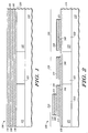
- FIG. 1 is a cross-sectional view of a portion of a semiconductor device 100 at a particular stage in a manufacturing process according to an embodiment of the invention.
- semiconductor device 100 comprises a semiconductor substrate 110, a patterned interconnect layer 120 above semiconductor substrate 110, a dielectric material 130 over patterned interconnect layer 120, an electrode material 140 over dielectric material 130, a dielectric material 150 over electrode material 140, an electrode material 160 over dielectric material 150, and a dielectric material 170 over electrode material 160.
- patterned interconnect layer 120 can comprise copper, including, in one embodiment, damascene copper. Patterned interconnect layer 120 can also comprise aluminum or another conductive material as known in the art. In one embodiment, patterned interconnect layer 120 can comprise a portion 121 and a portion 122 separated from portion 121 by a gap 123. In at least one embodiment, gap 123 represents a region of silicon dioxide, a region of silicon-dioxide-based material, or a region of material having a low dielectric constant.
- dielectric material 130 can comprise silicon nitride or another dielectric material not containing oxygen.
- dielectric material 130 comprises plasma-enhanced nitride (PEN).
- dielectric material 150 can comprise a material or a combination of materials having an effective dielectric constant greater than approximately eight, and preferably greater than approximately twenty.
- dielectric material 150 comprises a stack comprising a first layer of hafnium oxide, a layer of tantalum oxide above the first layer of hafnium oxide, and a second layer of hafnium oxide above the layer of tantalum oxide.
- dielectric material 150 can comprise zirconium oxide, aluminum oxide, titanium oxide, barium-strontium-titanate (BST), silicon nitride (including PEN).
- dielectric material 150 can comprise a laminate structure in which multiple layers of any of the foregoing materials, or other similar materials not mentioned herein, are stacked one above another.
- the particular layers of the laminate structure that are to contact an adjacent material, such as an electrode material are chosen so as to be compatible with that adjacent material.
- compatibility means compatibility in terms of material adhesion properties, chemical and electrical interaction properties, and the like. As an example, tantalum oxide cannot be placed directly on top of copper because the tantalum oxide will oxidize the copper.
- tantalum oxide cannot be placed directly on top of tantalum nitride because the oxygen will diffuse into the tantalum nitride and the nitrogen will diffuse into the tantalum oxide, thus negatively affecting the electric properties of the electrode material and the dielectric properties of the dielectric material, respectively.
- Hafnium oxide in contrast, does not exhibit an unwanted reaction with tantalum nitride.
- dielectric material 150 can comprise a mixture in which any of a variety of combinations of any of the foregoing materi als, or other similar materials not mentioned herein, in any of a variety of proportions, are mixed together to form a layer or layers of dielectric material.
- electrode material 140 can comprise tantalum nitride, titanium nitride, tantalum, tungsten-based metals, nickel-based metals, other refractory metals, and similar materials. As further discussed below, a portion of electrode material 140 is used, according to the invention, as a resistor, while, in certain embodiments of the invention, no portion of electrode material 160 is used as a resistor. Accordingly, electrode material 160 can comprise any of the materials listed above for electrode material 140, and can also comprise more highly-conductive materials such as copper, aluminum, gold, and the like.
- Dielectric material 170 can be similar in composition to dielectric material 130, and can also comprise, for example, amorphous carbon. Dielectric material 170, in at least one embodiment, serves no electrical function, but can act as an etch stop for a via etch, and/or as a hard mask during the subsequent patterning of electrode material 160. In addition to serving as the insulator in a MIM capacitor, dielectric materials 150 and 130 can also serve as etch stops, and dielectric material 150 can further serve as a hard mask, during the subsequent patterning of electrode material 160.
- FIG. 2 is a cross-sectional view of a portion of semiconductor device 100 at a later stage of the manufacturing process according to an embodiment of the invention.
- dielectric material 170 and electrode material 160 have been patterned to form an electrode 211 of a capacitor 210.
- dielectric material 150 and electrode material 140 have been patterned to form an electrode 221 of a capacitor 220, to form an electrode 212 of capacitor 210, and to define a resistor 230. At least portions of capacitors 210 and 220 and resistor 230 are formed above patterned interconnect layer 120.
- portion 121 of patterned interconnect layer 120 forms an electrode 213 of capacitor 210.
- portion 122 of patterned interconnect layer 120 forms an electrode 222 of capacitor 220.
- electrode 211 is a top electrode of capacitor 210
- electrode 212 can be a middle electrode of capacitor 210
- electrode 213 can be a bottom electrode of capacitor 210
- electrode 221 is a top electrode of capacitor 220 and electrode 222 is a bottom electrode of capacitor 220.
- capacitor 210 can have a high capacitive density.
- capacitor 210 can have a high capacitance per unit area, defined herein as a capacitance per unit area (C/A) equal to or greater than approximately 4 femto-Farads per square micrometer (fF/ ⁇ m 2 ).
- capacitor 220 can have a lower capacitance per unit area but a higher quality than capacitor 210.
- capacitor 220 can have a C/A of approximately 1.6 fF/ ⁇ m 2 .
- Capacitor 220 can have a higher quality than capacitor 210 in part because capacitor 220 contains dielectric materials that perform better with respect to, for example, leakage current, linearity, and/or reliability than at least some of the materials that make up capacitor 210.
- differences in the dielectric materials that form a part of capacitors 210 and 220 also contribute to the differences in quality and capacitance per unit area between capacitors 210 and 220.
- at least one of the dielectric layers of capacitor 210 comprises a material that is different from a material of at least one of the dielectric layers of capacitor 220. Specific examples of some acceptable dielectric materials for capacitors 210 and 220 were given above.
- capacitor 220 can have one or more of a high linearity, a low TCC, and a low leakage material, making capacitor 220 a high performance capacitor.
- Resistor 230 can be, for example, a high performance thin film resistor.
- semiconductor device 100 offers greater performance flexibility than would a semiconductor device having only a single capacitor, whether the single capacitor had a high capacitive density or high linearity, low TCC, or low leakage.
- a semiconductor device such as semiconductor device 100 may be useful in communication systems, both wireless and wire based.
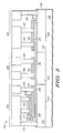
- FIG. 3 is a cross-sectional view of a portion of semiconductor device 100 at a later stage of the manufacturing process according to an embodiment of the invention.
- an electrical contact 311 has been coupled to electrode 213 of capacitor 210
- electrical contacts 312 and 313 have been coupled to electrode 211 of capacitor 210
- electrical contact 314 has been coupled to electrode 212 of capacitor 210.
- electrical contacts 321 and 322 have been coupled to electrode 221 of capacitor 220
- an electrical contact 323 has been coupled to electrode 222 of capacitor 220
- electrical contacts 331 and 332 have been coupled to resistor 230.
- resistor 230 could, in certain embodiments, be coupled to further electrical contacts in addition to the two electrical contacts 331 and 332 illustrated in FIG. 3 .
- electrodes 211, 212, and 213 of capacitor 210 and electrodes 221 and 222 of capacitor 220 could be coupled to further electrical contacts in addition to the one or two electrical contacts illustrated in FIG. 3 to be coupled to electrodes 211, 212, 213, 221, and 222.
- capacitor 210 comprises a stacked capacitor having two MIM capacitors wired in parallel. With multiple MIM capacitors wired in parallel, capacitor 210 potentially has a higher C/A than a non-stacked capacitor, but would possibly be of lower quality than the non-stacked capacitor because of the lower quality of the dielectric materials of the stacked capacitor.
- At least electrical contacts 311, 312, 313, 314, 321, 322, and 323 are formed substantially simultaneously with each other.
- at least electrical contacts 312, 313, 314, 321, 322, and 323 are formed substantially simultaneously with each other, but electrical contact 311 is not formed.
- electrode 213 of capacitor 210 would be electrically connected through portion 121 to another portion of the integrated circuit. It will be recognized by one of ordinary skill in the art that portion 121 can, but does not necessarily, extend underneath all of electrodes 211 or 212. Similarly, portion 122 can, but does not necessarily, extend underneath all of electrode 221. Furthermore, portions 121 and 122 are not necessarily continuous underneath electrodes 211, 212, and 221.
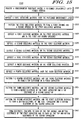
- FIG. 4 is a flowchart illustrating a method 400 of making semiconductor device 100 according to an embodiment of the invention.
- Method 400 comprises, among other steps, two patterning steps, indicating that method 400 is a two-mask manufacturing method integrating a one-mask and a two-mask MIM capacitor with a resistor on a single integrated circuit.
- the two masks referred to in the preceding sentence are the masks required to form a MIM capacitor in accordance with an embodiment of the invention, and that additional masks may be required to form other portions of the integrated circuit, such as, for example, the patterned interconnect layer, the upper interconnect structure, optional layers not required to form the basic MIM capacitor structure, and the like.
- a step 410 of method 400 is to provide a semiconductor substrate having a patterned interconnect layer formed thereon.
- the semiconductor substrate can be similar to semiconductor substrate 110, first shown in FIG. 1
- the patterned interconnect layer can be similar to patterned interconnect layer 120, also first shown in FIG. 1 .
- a step 420 of method 400 is to deposit a first dielectric material over the patterned interconnect layer.
- the first dielectric material can be similar to dielectric material 130, first shown in FIG. 1 .
- a step 430 of method 400 is to deposit a first electrode material over the first dielectric material.
- the first electrode material can be similar to electrode material 140, first shown in FIG. 1 .
- a step 440 of method 400 is to deposit a second dielectric material over the first electrode material.
- the second dielectric material can be similar to dielectric material 150, first shown in FIG. 1 .
- a step 450 of method 400 is to deposit a second electrode material over the second dielectric material.
- the second electrode material can be similar to electrode material 160, first shown in FIG. 1 .
- a step 460 of method 400 is to deposit a third dielectric material over the second electrode material.
- the third dielectric material can be similar to dielectric material 170, first shown in FIG. 1 .
- a step 470 of method 400 is to pattern the third dielectric material and the second electrode material, using a first mask, to form a top electrode of a first capacitor.
- the first capacitor can be similar to capacitor 210, first shown in FIG. 2
- the top electrode of the first capacitor can be similar to electrode 211, also first shown in FIG. 2 .
- a step 480 of method 400 is to pattern the second dielectric material and the first electrode material, using a second mask, to form a top electrode of a second capacitor, to form a middle electrode of the first capacitor, and to define a resistor.
- the second capacitor can be similar to capacitor 220
- the top electrode of the second capacitor can be similar to electrode 221
- the middle electrode can be similar to electrode 212
- the resistor can be similar to resistor 230, all of which are first shown in FIG. 2 .
- a step 490 of method 400 is to form at least one electrical contact coupled to at least the top and middle electrodes of the first capacitor and to at least the top electrode of the second capacitor, and to form at least two electrical contacts to the resistor.
- the electrical contacts can be similar to one or more of electrical contacts 311, 312, 313, 314, 321, 322, 323, 331, and 332, all of which were first shown in FIG. 3 .
- step 480 comprises forming the electrical contacts simultaneously with each other.
- the patterned interconnect layer forms a bottom electrode of the second capacitor and is absent from the first capacitor.
- the patterned interconnect layer forms a bottom electrode of the first capacitor and a bottom electrode of the second capacitor.
- the electrode of the first capacitor comprises a middle electrode of the first capacitor, and the middle electrode of the first capacitor is located between the top electrode of the first capacitor and the bottom electrode of the first capacitor.
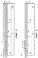
- FIG. 5 is a cross-sectional view of a portion of a semiconductor device 500 at a particular stage in a manufacturing process according to an embodiment of the invention.
- semiconductor device 500 comprises a semiconductor substrate 510, a patterned interconnect layer 520 above semiconductor substrate 510, a dielectric material 530 over patterned interconnect layer 520, an electrode material 540 over dielectric material 530, a dielectric material 550 over electrode material 540, an electrode material 560 over dielectric material 550, and a dielectric material 570 over electrode material 560.
- semiconductor substrate 510, patterned interconnect layer 520, dielectric material 530, electrode material 540, dielectric material 550, electrode material 560, and dielectric material 570 can be similar to semiconductor substrate 110, patterned interconnect layer 120, dielectric material 130, electrode material 140, dielectric material 150, electrode material 160, and dielectric material 170, respectively, first shown in FIG. 1 .
- patterned interconnect layer 520 comprises a portion 521 and a portion 522 separated from portion 521 by a gap 523. Portion 521, portion 522, and gap 523 can be similar to, respectively, portion 121, portion 122, and gap 123, first shown in FIG. 1 .
- dielectric material 530 has been patterned to form an opening 531 that exposes a portion 525 of patterned interconnect layer 520
- electrode material 540 has been deposited over dielectric material 530 and within opening 531 such that electrode material 540 physically and electrically contacts, or is coupled to, portion 525 of patterned interconnect layer 520.
- FIG. 6 is a cross-sectional view of a portion of semiconductor device 500 at a later stage of the manufacturing process according to an embodiment of the invention. As illustrated in FIG. 6 , dielectric material 570 and electrode material 560 have been patterned to form an electrode 611. As an example, electrode 611 can be similar to electrode 211, first shown in FIG. 2 .
- FIG. 7 is a cross-sectional view of semiconductor device 500 at a later stage of the manufacturing process according to an embodiment of the invention.
- electrode 611 is an electrode of a capacitor 710.
- dielectric material 550 and electrode material 540 have been patterned to form an electrode 721 of a capacitor 720, to form an electrode 712 of capacitor 710, and to define a resistor 730.
- At least portions of capacitors 710 and 720 and resistor 730 are formed above patterned interconnect layer 520.
- electrode 721 and resistor 730 can be similar to, respectively, electrode 221 and resistor 230, both of which were first shown in FIG. 2 .
- capacitor 710 can be similar to capacitor 210, first shown in FIG. 2 , in that capacitor 710, like capacitor 210, can have a high capacitive density.
- capacitor 720 can be similar to capacitor 220, first shown in FIG. 2 , in that capacitor 720 can have a higher quality than capacitor 710, just as capacitor 220 can have a higher quality than capacitor 210.
- portion 521 of patterned interconnect layer 520 forms an electrode 713 of capacitor 710. In that embodiment, electrode 713 and electrode 712 form a bottom electrode of capacitor 710. In a different embodiment, where portion 521 does not form electrode 713, electrode 712 forms a bottom electrode of capacitor 710. In the same or another embodiment, portion 522 of patterned interconnect layer 520 forms an electrode 722 of capacitor 720.
- FIG. 8 is a cross-sectional view of a portion of semiconductor device 500 at a later stage of the manufacturing process according to an embodiment of the invention.
- an electrical contact 811 has been coupled to electrode 713 of capacitor 710
- electrical contacts 812 and 813 have been coupled to electrode 611 of capacitor 710
- electrical contact 814 has been coupled to electrode 712 of capacitor 710. It will be understood by one of ordinary skill in the art that electrical contact 814 would be formed only in those embodiments where portion 521 of patterned interconnect layer 520 is absent. In embodiments where portion 521 is present, electrical contact to electrode 712 is accomplished via portion 521.
- electrical contacts 821 and 822 have been coupled to electrode 721 of capacitor 720
- an electrical contact 823 has been coupled to electrode 722 of capacitor 720
- electrical contacts 831 and 832 have been coupled to resistor 730.
- resistor 730 could, in certain embodiments, be coupled to further electrical contacts in addition to the two electrical contacts 831 and 832 illustrated in FIG. 8 .
- electrodes 611, 712, and 713 of capacitor 710 and electrodes 721 and 722 of capacitor 720 could be coupled to further electrical contacts in addition to the one or two electrical contacts illustrated in FIG. 8 to be coupled to electrodes 611, 712, 713, 721, and 722.
- At least electrical contacts 811, 812, 813, 814, 821, 822, and 823 are formed substantially simultaneously with each other.
- at least electrical contacts 812, 813, 814, 821, and 822 are formed substantially simultaneously with each other, but electrical contact 811 and/or electrical contact 823 are not formed.
- electrode 713 of capacitor 710 and/or electrode 722 of capacitor 720 would be electrically connected through portion 521 and portion 522, respectively, to another portion of the integrated circuit.
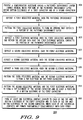
- FIG. 9 is a flowchart illustrating a method 900 of making semiconductor device 500 according to an embodiment of the invention.
- Method 900 comprises, among other steps, three patterning steps, indicating that method 900 is a three-mask manufacturing method integrating a one-mask and a three-mask MIM capacitor with a resistor on a single integrated circuit.
- the three masks referred to in the preceding sentence are the masks required to form a MIM capacitor in accordance with an embodiment of the invention, and that additional masks may be required to form other portions of the integrated circuit, such as, for example, the patterned interconnect layer, the upper interconnect structure, optional layers not required to form the basic MIM capacitor structure, and the like.
- a step 905 of method 900 is to provide a semiconductor substrate having a patterned interconnect layer formed thereon, where portions of the patterned interconnect layer define bottom electrodes of a first capacitor and of a second capacitor.
- the semiconductor substrate can be similar to semiconductor substrate 510, first shown in FIG. 5
- the patterned interconnect layer can be similar to patterned interconnect layer 520, also first shown in FIG. 5 .
- the first capacitor can be similar to capacitor 710, first shown in FIG. 7
- the second capacitor can be similar to capacitor 720, also first shown in FIG. 7 .
- the portions of the patterned interconnect layer defining bottom electrodes of the first and second capacitors can be similar to portions 521 and 522, first shown in FIG. 5 .
- a step 910 of method 900 is to deposit a first dielectric material over the patterned interconnect layer.
- the first dielectric material can be similar to dielectric material 530, first shown in FIG. 5 .
- a step 915 of method 900 is to pattern the first dielectric material, using a first mask, to form an opening that exposes a portion of the patterned interconnect layer.
- the opening can be similar to opening 531, and the exposed portion of the patterned interconnect layer can be similar to portion 525, both of which are first shown in FIG. 5 .
- a step 920 of method 900 is to deposit a first electrode material over the first dielectric material and within the opening such that the first electrode material contacts the portion of the patterned interconnect layer.
- the first electrode material can be similar to electrode material 540, first shown in FIG. 5 .
- a step 925 of method 900 is to deposit a second dielectric material over the first electrode material.
- the second dielectric material can be similar to dielectric material 550, first shown in FIG. 5 .
- a step 930 of method 900 is to deposit a second electrode material over the second dielectric material.
- the second electrode material can be similar to electrode material 560, first shown in FIG. 5 .
- a step 935 of method 900 is to deposit a third dielectric material over the second electrode material.
- the third dielectric material can be similar to dielectric material 570, first shown in FIG. 5 .
- a step 940 of method 900 is to pattern the third dielectric material and the second electrode material, using a second mask, to form a top electrode of the first capacitor.
- the top electrode of the first capacitor can be similar to electrode 611, first shown in FIG. 6 .
- a step 945 of method 900 is to pattern the second dielectric material and the first electrode material, using a third mask, to form a top electrode of the second capacitor and at least a portion of a bottom electrode of the first capacitor.
- the top electrode of the second capacitor can be similar to electrode 721, first shown in FIG. 7
- the bottom electrode, or portion of the bottom electrode, of the first capacitor can be similar to electrode 712, first shown in FIG. 7 .
- step 945 further comprises forming a resistor.
- the resistor can be similar to resistor 730, first shown in FIG. 7 . it.
- a step 950 of method 900 is to form at least one electrical contact coupled to each of the top and bottom electrodes of the first capacitor and to each of the top and bottom electrodes of the second capacitor, where each of the electrical contacts are formed substantially simultaneously with each other.
- step 950 can comprise forming electrical contacts coupled to each of the top electrode of the first capacitor and to each of the top and bottom electrodes of the second capacitor, but not to the bottom electrode of the first capacitor.
- electrode 713 of capacitor 710 would be electrically connected through portion 521 to another portion of the integrated circuit.
- step 950 can comprise forming electrical contacts to the top electrode of the first capacitor and to the top electrode of the second capacitor, but: (1) not to the bottom electrode of the first capacitor or to the bottom electrode of the second capacitor; and/or (2) not to the bottom electrode of the second capacitor.
- electrode 713 of capacitor 710 and/or electrode 722 of capacitor 720 would be electrically connected through portions 521 and 522, respectively, to another portion of the integrated circuit.
- step 950 or another step can further comprise forming electrical contacts to the resistor.
- the electrical contacts can be similar to one or more of electrical contacts 811, 812, 813, 814, 821, 822, 823, 831, and 832, all of which were first shown in FIG. 8 .
- FIGS. 10-15 describe a not-claimed manufacturing process.
- FIG. 10 is a cross-sectional view of a portion of a semiconductor device 1000 at a particular stage of a manufacturing process not forming part of the claimed invention.
- semiconductor device 1000 comprises a semiconductor substrate 1010, a patterned interconnect layer 1020 formed on semiconductor substrate 1010, a dielectric material 1090 over patterned interconnect layer 1020, an electrode material 1080 over dielectric material 1090, a dielectric material 1030 over electrode material 1080, an electrode material 1040 over dielectric material 1030, a dielectric material 1050 over electrode material 1040, an electrode material 1060 over dielectric material 1050, and a dielectric material 1070 over electrode material 1060.
- semiconductor substrate 1010, patterned interconnect layer 1020, dielectric material 1030, electrode material 1040, dielectric material 1050, electrode material 1060, and dielectric material 1070 can be similar to semiconductor substrate 110, patterned interconnect layer 120, dielectric material 130, electrode material 140, dielectric material 150, electrode material 160, and dielectric material 170, respectively, first shown in FIG. 1 .
- electrode material 1080 can be similar to electrode material 140 and dielectric material 1090 can be similar to dielectric material 130, both of which are first shown in FIG. 1 .
- patterned interconnect layer 1020 comprises a portion 1021 and a portion 1022 separated from portion 1021 by a gap 1023.
- Portion 1021, portion 1022, and gap 1023 can be similar to, respectively, portion 121, portion 122, and gap 123, first shown in FIG. 1 .
- dielectric material 1090 has been patterned to form an opening 1031 and an opening 1032 that expose portions of patterned interconnect layer 1020
- electrode material 1080 has been deposited over dielectric material 1090 and within openings 1031 and 1032 such that electrode material 1080 physically and electrically contacts, or is coupled to, the exposed portions of patterned interconnect layer 1020.
- FIG. 11 is a cross-sectional view of a portion of semiconductor device 1000 at a later stage of the manufacturing process. As illustrated in FIG. 11 , dielectric material 1070 and electrode material 1060 have been patterned to form an electrode 1111. As an example, electrode 1111 can be similar to electrode 211, first shown in FIG. 2 .
- FIG. 12 is a cross-sectional view of semiconductor device 1000 at a later stage of the manufacturing process. As illustrated in FIG. 12 , dielectric material 1050 and electrode material 1040 have been patterned to form an electrode 1212 and an electrode 1221. As an example, electrode 1221 can be similar to electrode 721, first shown in FIG. 7 .
- FIG. 13 is a cross-sectional view of a portion of semiconductor device 1000 at a later stage of the manufacturing process.
- electrodes 1111 and 1212 are electrodes of a capacitor 1310.
- electrode 1221 is an electrode of a capacitor 1320.
- dielectric material 1030 and electrode material 1080 have been patterned to form an electrode 1313 of capacitor 1310, an electrode 1322 of capacitor 1320, and a resistor 1330. At least portions of capacitors 1310 and 1320 and resistor 1330 are formed above patterned interconnect layer 1020.
- electrode 1212 and electrode 1221 can be similar to, respectively, electrode 212 and electrode 221, both of which were first shown in FIG. 2 .
- capacitor 1310 can be similar to capacitor 210, first shown in FIG. 2 , in that capacitor 1310, like capacitor 210, can have a high capacitive density.
- capacitor 1320 can be similar to capacitor 220, first shown in FIG. 2 , in that capacitor 1320 can have a higher quality than capacitor 1310, just as capacitor 220 can have a higher quality than capacitor 210.
- FIG. 14 is a cross-sectional view of a portion of semiconductor device 1000 at a later stage of the manufacturing process.
- an electrical contact 1411 has been coupled to electrode 1313 of capacitor 1310
- electrical contacts 1412 and 1413 have been coupled to electrode 1111 of capacitor 1310
- an electrical contact 1414 has been coupled to electrode 1212 of capacitor 1310
- an electrical contact 1415 has been coupled to portion 1021 of patterned interconnect layer 1020.
- electrical contacts 1421 and 1422 have been coupled to electrode 1221 of capacitor 1320, an electrical contact 1423 has been coupled to electrode 1322 of capacitor 1320, an electrical contact 1424 has been coupled to portion 1022 of patterned interconnect layer 1020, and electrical contacts 1431 and 1432 have been coupled to resistor 1330.
- Electrical contact to electrode 1313 of capacitor 1310 may be accomplished using any of a variety of methods. As an example, electrical contact to electrode 1313 may be accomplished via electrical contact 1411 alone, electrical contact 1415 alone, or portion 1021 of patterned interconnect layer 1020 alone. As another example, electrical contact to electrode 1313 may be accomplished via any two of electrical contacts 1411 and 1415 and portion 1021 of patterned interconnect layer 1020, i.e., via electrical contacts 1411 and 1415, via electrical contact 1411 and portion 1021, or via electrical contact 1415 and portion 1021. As still another example, electrical contact to electrode 1313 may be accomplished via all three of electrical contacts 1411 and 1415 and portion 1021 of patterned interconnect layer 1020 simultaneously.
- electrical contact to electrode 1322 of capacitor 1320 may be accomplished in a variety of ways.
- electrical contact to electrode 1322 may be accomplished via electrical contact 1423 alone, electrical contact 1424 alone, or portion 1022 of patterned interconnect layer 1020 alone.
- electrical contact to electrode 1322 may be accomplished via any two of electrical contacts 1423 and 1424 and portion 1022 of patterned interconnect layer 1020, i.e., via electrical contacts 1423 and 1424, via electrical contact 1423 and portion 1022, or via electrical contact 1424 and portion 1022.
- electrical contact to electrode 1322 may be accomplished via all three of electrical contacts 1423 and 1424 and portion 1022 of patterned interconnect layer 1020 simultaneously.
- resistor 1330 could, in certain examples, be coupled to further electrical contacts in addition to the two electrical contacts 1431 and 1432 illustrated in FIG. 14 .
- electrodes 1111, 1212, and 1313 of capacitor 1310 and electrodes 1221 and 1322 of capacitor 1320 could be coupled to further electrical contacts in addition to the one or two electrical contacts illustrated in FIG. 14 to be coupled to electrodes 1111, 1212, 1313, 1221, and 1322.
- capacitor 1310 like capacitor 210, comprises a stacked capacitor having two MIM capacitors wired in parallel.
- At least electrical contacts 1411, 1412, 1413, 1414, 1421, 1422, and 1423 are formed substantially simultaneously with each other.
- at least electrical contacts 1412, 1413, 1414, 1421, 1422, and 1423 are formed substantially simultaneously with each other, but electrical contact 1411 is not formed.
- electrode 1313 of capacitor 1310 would be electrically connected through portion 1021 to another portion of the integrated circuit.
- FIG. 15 is a flowchart illustrating a method 1500 of making semiconductor device 1000.
- Method 1500 comprises, among other steps, four patterning steps, indicating that method 1500 is a four-mask manufacturing method integrating a two-mask and a three-mask MIM capacitor with a resistor on a single integrated circuit.
- the four masks referred to in the preceding sentence are the masks required to form a MIM capacitor , and that additional masks may be required to form other portions of the integrated circuit, such as, for example, the patterned interconnect layer, the upper interconnect structure, optional layers not required to form the basic MIM capacitor structure, and the like.
- a step 1505 of method 1500 is to provide a semiconductor substrate having a patterned interconnect layer formed thereon.
- the semiconductor substrate can be similar to semiconductor substrate 1010, first shown in FIG. 10 .
- the patterned interconnect layer can be similar to patterned interconnect layer 1020, also first shown in FIG. 10 .
- a step 1510 of method 1500 is to deposit a first dielectric material over the patterned interconnect layer.
- the first dielectric material can be similar to dielectric material 1090, first shown in FIG. 10 .
- a step 1515 of method 1500 is to pattern the first dielectric material, using a first mask, to form a first opening and a second opening in the first dielectric material.
- the first opening can be similar to opening 1031
- the second opening can be similar to opening 1032, both of which are first shown in FIG. 10 .
- a step 1520 of method 1500 is to deposit a first electrode material on the first dielectric material and in the first and second openings.
- the first electrode material can be similar to electrode material 1080, first shown in FIG. 10 .
- a step 1525 of method 1500 is to deposit a second dielectric material on the first electrode material.
- the second dielectric material can be similar to dielectric material 1030, first shown in FIG. 10 .
- a step 1530 of method 1500 is to deposit a second electrode material on the second dielectric material.
- the second electrode material can be similar to electrode material 1040, first shown in FIG. 10 .
- a step 1535 of method 1500 is to deposit a third dielectric material on the second electrode material.
- the third dielectric material can be similar to dielectric material 1050, first shown in FIG. 10 .
- a step 1540 of method 1500 is to deposit a third electrode material on the third dielectric material.
- the third electrode material can be similar to electrode material 1060, first shown in FIG. 10 .
- a step 1545 of method 1500 is to deposit a fourth dielectric material over the third electrode material.
- the fourth dielectric material can be similar to dielectric material 1070, first shown in FIG. 10 .
- a step 1550 of method 1500 is to pattern the fourth dielectric material and the third electrode material, using a second mask, to form a top electrode of a first capacitor.
- the first capacitor can be similar to capacitor 1310, first shown in FIG. 13
- the top electrode of the first capacitor can be similar to electrode 1111, first shown in FIG. 11 .
- a step 1555 of method 1500 is to pattern the third dielectric material and the second electrode material, using a third mask, to form a middle electrode of the first capacitor and a top electrode of a second capacitor.
- the second capacitor can be similar to capacitor 1320, first shown in FIG. 13 .
- the middle electrode of the first capacitor can be similar to electrode 1212, first shown in FIG. 12
- the top electrode of the second capacitor can be similar to electrode 1221, also first shown in FIG. 12 .
- a step 1560 of method 1500 is to pattern the second dielectric material and the first electrode material, using a fourth mask, to form a bottom electrode of the first capacitor, a bottom electrode of the second capacitor.
- performing step 1560 also forms a resistor.
- the bottom electrode of the first capacitor can be similar to electrode 1313
- the bottom electrode of the second capacitor can be similar to electrode 1322, both of which are first shown in FIG. 13 .
- the resistor can be similar to resistor 1330, also first shown in FIG. 13 .
- a step 1565 of method 1500 is to form electrical contacts to each of the top, middle, and bottom electrodes of the first capacitor and to each of the top and bottom electrodes of the second capacitor.
- step 1565 or another step can further comprise forming electrical contacts to the resistor.
- the electrical contacts can be similar to one or more of electrical contacts 1411, 1412, 1413, 1414, 1415, 1421, 1422, 1423, 1424, 1431, and 1432, all of which were first shown in FIG. 14 .
- a semiconductor device having dual MIM capacitors can be formed by: providing a semiconductor substrate having a patterned interconnect layer formed thereon; depositing a first dielectric material on the patterned interconnect layer; patterning the first dielectric material to create a first opening to the patterned interconnect layer for a first capacitor; depositing a first electrode material over the first dielectric material and in the first opening; depositing a second dielectric material over the first electrode material; patterning the second dielectric material, the first electrode material, and the first dielectric material to create a second opening to the patterned interconnect layer for a second capacitor; depositing a second electrode material over the second dielectric material and in the second opening; depositing a third dielectric material over the second electrode material; patterning the third dielectric material and the second electrode material to define a top electrode for the first capacitor and a
- the structure formed by the process described in the preceding paragraph can comprise a first capacitor similar to capacitor 710, first shown in FIG. 7 , but differing at least in that additional dielectric and/or electrode material can be located at either or both ends of an electrode analogous to electrode 611 and above a portion of a dielectric material analogous to dielectric material 550. Additionally, the structure formed by the process described in the preceding paragraph can further comprise a second capacitor similar to capacitor 1320, first shown in FIG.
- the structure formed by the process described in the preceding paragraph can further comprise a resistor similar to, for example, resistor 1330, first shown in FIG. 13 .
- FIG. 16 is a cross-sectional view of a portion of a semiconductor device 1600 at a particular stage of a manufacturing process according to an embodiment of the invention.
- semiconductor device 1600 comprises a semiconductor substrate 1610 having a patterned interconnect layer 1620 formed thereon, a dielectric material 1630 over patterned interconnect layer 1620, an electrode material 1640 over dielectric material 1630, a dielectric material 1650 over electrode material 1640, an electrode material 1660 over dielectric material 1650, and a dielectric material 1670 over electrode material 1660.
- semiconductor substrate 1610, dielectric material 1630, electrode material 1640, dielectric material 1650, electrode material 1660, and dielectric material 1670 can be similar to, respectively, semiconductor substrate 110, dielectric material 130, electrode material 140, dielectric material 150, electrode material 160, and dielectric material 170, all of which were first shown in FIG. 1 .
- patterned interconnect layer 1620 can be similar to patterned interconnect layer 120, first shown in FIG. 1 , except patterned interconnect layer 1620, in the illustrated embodiment, comprises only a portion 1622, corresponding to portion 122 of patterned interconnect layer 120. Any portion corresponding to portion 121 of patterned interconnect layer 120 is absent from patterned interconnect layer 1620.
- dielectric material 1670 and electrode material 1660 have been patterned to form an electrode 1611 of a capacitor 1615.
- dielectric material 1650 and electrode material 1640 have been patterned to form an electrode 1621 of a capacitor 1625, and to form an electrode 1612 of capacitor 1615. At least portions of capacitors 1615 and 1625 are formed above patterned interconnect layer 1620.
- portion 1622 of patterned interconnect layer 1620 forms an electrode 1682 of capacitor 1625.
- electrode 1611 is a top electrode of capacitor 1615
- electrode 1612 can be a bottom electrode of capacitor 1615
- electrode 1621 is a top electrode of capacitor 1625 and electrode 1682 is a bottom electrode of capacitor 1625.
- electrical contacts 1662 and 1663 have been coupled to electrode 1611 of capacitor 1615, and electrical contact 1664 has been coupled to electrode 1612 of capacitor 1615.
- Electrical contacts 1671 and 1672 have been coupled to electrode 1621 of capacitor 1625, and an electrical contact 1673 has been coupled to electrode 1682 of capacitor 1625.
- electrodes 1611 and 1612 of capacitor 1615 and electrodes 1621 and 1682 of capacitor 1625 could be coupled to further electrical contacts in addition to the one or two electrical contacts illustrated in FIG. 16 to be coupled to electrodes 1611, 1612, 1621, and 1682.
- at least electrical contacts 1662, 1663, 1664, 1671, 1672, and 1673 are formed substantially simultaneously with each other.
- Semiconductor device 1600 further comprises a portion 1690 formed by portions of electrode material 1640 and dielectric material 1650.
- portion 1690 is used to form a resistor, which resistor can be similar to resistor 230, first shown in FIG. 2 .
- electrical contacts can be coupled to the resistor in a manner similar to that shown and described for resistor 230.
- FIG. 17 is a flow chart illustrating a method 1700 of making semiconductor device 1600 according to an embodiment of the invention.
- a step 1710 of method 1700 is to provide a semiconductor substrate having a patterned interconnect layer formed thereon, where the patterned interconnect layer forms a bottom electrode of a second capacitor and is absent from a first capacitor.
- the semiconductor substrate can be similar to semiconductor substrate 1610, first shown in FIG. 16
- the patterned interconnect layer can be similar to patterned interconnect layer 1620, also first shown in FIG. 16 .
- the first capacitor can be similar to capacitor 1615
- the second capacitor can be similar to capacitor 1625
- the bottom electrode of the second capacitor can be similar to electrode 1682, all of which were first shown in FIG. 16 .
- a step 1720 of method 1700 is to deposit a first dielectric material over the patterned interconnect layer.
- the first dielectric material can be similar to dielectric material 1630, first shown in FIG. 16 .
- a step 1730 of method 1700 is to deposit a first electrode material over the first dielectric material.
- the first electrode material can be similar to electrode material 1640, first shown in FIG. 16 .
- a step 1740 of method 1700 is to deposit a second dielectric material over the first electrode material.
- the second dielectric material can be similar to dielectric material 1650, first shown in FIG. 16 .
- a step 1750 of method 1700 is to deposit a second electrode material over the second dielectric material.
- the second electrode material can be similar to electrode material 1660, first shown in FIG. 16 .
- a step 1760 of method 1700 is to deposit a third dielectric material over the second electrode material.
- the third dielectric material can be similar to dielectric material 1670, first shown in FIG. 16 .
- a step 1770 of method 1700 is to pattern the third dielectric material and the second electrode material to form a top electrode of the first capacitor.
- the top electrode of the first capacitor can be similar to electrode 1611, first shown in FIG. 16 .
- a step 1780 of method 1700 is to pattern the second dielectric material and the first electrode material to form a top electrode of the second capacitor and an electrode of the first capacitor.
- the top electrode of the second capacitor can be similar to electrode 1621 and the electrode can be similar to electrode 1612, both of which are first shown in FIG. 16 .
- a step 1790 of method 1700 is to form at least one electrical contact coupled to at least the top and bottom electrodes of the first capacitor and to the top and bottom electrodes of the second capacitor.
- the electrical contacts can be similar to one or more of electrical contacts 1662, 1663, 1664, 1671, 1672, and 1673, all of which were first shown in FIG. 16 .
- step 1790 comprises forming the electrical contacts simultaneously with each other.
- step 1780 is used to form a resistor over the semiconductor substrate.
- the resistor can be similar to 230, first shown in FIG. 2 .
- the resistor is formed using a portion of the first electrode material and the second dielectric material.
- the portion of the first electrode material and the second dielectric material can be similar to portion 1690, first shown in FIG. 16 .
Landscapes
- Engineering & Computer Science (AREA)
- Power Engineering (AREA)
- Physics & Mathematics (AREA)
- Condensed Matter Physics & Semiconductors (AREA)
- General Physics & Mathematics (AREA)
- Computer Hardware Design (AREA)
- Microelectronics & Electronic Packaging (AREA)
- Semiconductor Integrated Circuits (AREA)
- Internal Circuitry In Semiconductor Integrated Circuit Devices (AREA)
Priority Applications (1)
| Application Number | Priority Date | Filing Date | Title |
|---|---|---|---|
| EP12180945.3A EP2528086A3 (en) | 2004-03-10 | 2005-02-10 | Semiconductor device comprising a resistor and two capacitors of different capacitance |
Applications Claiming Priority (2)
| Application Number | Priority Date | Filing Date | Title |
|---|---|---|---|
| US10/799,554 US6919244B1 (en) | 2004-03-10 | 2004-03-10 | Method of making a semiconductor device, and semiconductor device made thereby |
| PCT/US2005/004008 WO2005091795A2 (en) | 2004-03-10 | 2005-02-10 | Method of making a semiconductor device, and semiconductor device made thereby |
Related Child Applications (1)
| Application Number | Title | Priority Date | Filing Date |
|---|---|---|---|
| EP12180945.3 Division-Into | 2012-08-17 |
Publications (3)
| Publication Number | Publication Date |
|---|---|
| EP1723673A2 EP1723673A2 (en) | 2006-11-22 |
| EP1723673A4 EP1723673A4 (en) | 2010-06-16 |
| EP1723673B1 true EP1723673B1 (en) | 2013-09-04 |
Family
ID=34740180
Family Applications (2)
| Application Number | Title | Priority Date | Filing Date |
|---|---|---|---|
| EP05713151.8A Expired - Lifetime EP1723673B1 (en) | 2004-03-10 | 2005-02-10 | Method of making a semiconductor device |
| EP12180945.3A Withdrawn EP2528086A3 (en) | 2004-03-10 | 2005-02-10 | Semiconductor device comprising a resistor and two capacitors of different capacitance |
Family Applications After (1)
| Application Number | Title | Priority Date | Filing Date |
|---|---|---|---|
| EP12180945.3A Withdrawn EP2528086A3 (en) | 2004-03-10 | 2005-02-10 | Semiconductor device comprising a resistor and two capacitors of different capacitance |
Country Status (6)
| Country | Link |
|---|---|
| US (2) | US6919244B1 (enExample) |
| EP (2) | EP1723673B1 (enExample) |
| JP (1) | JP4891224B2 (enExample) |
| KR (1) | KR101102785B1 (enExample) |
| CN (1) | CN100487896C (enExample) |
| WO (1) | WO2005091795A2 (enExample) |
Families Citing this family (38)
| Publication number | Priority date | Publication date | Assignee | Title |
|---|---|---|---|---|
| DE10260352A1 (de) * | 2002-12-20 | 2004-07-15 | Infineon Technologies Ag | Verfahren zum Herstellen einer Kondensatoranordnung und Kondensatoranordnung |
| JP4308691B2 (ja) * | 2004-03-19 | 2009-08-05 | 富士通マイクロエレクトロニクス株式会社 | 半導体基板および半導体基板の製造方法 |
| JP4707330B2 (ja) * | 2004-03-30 | 2011-06-22 | ルネサスエレクトロニクス株式会社 | 半導体装置およびその製造方法 |
| US20050255664A1 (en) * | 2004-05-12 | 2005-11-17 | Ching-Hung Kao | Method of forming a metal-insulator-metal capacitor |
| KR100685616B1 (ko) * | 2004-05-20 | 2007-02-22 | 매그나칩 반도체 유한회사 | 반도체 장치의 제조방법 |
| US7144784B2 (en) * | 2004-07-29 | 2006-12-05 | Freescale Semiconductor, Inc. | Method of forming a semiconductor device and structure thereof |
| KR100703965B1 (ko) * | 2004-12-31 | 2007-04-05 | 삼성전자주식회사 | 유전체막 장벽층을 구비한 반도체 소자 커패시터의 형성방법 및 이에 의해 제조된 반도체 소자의 커패시터 |
| KR100678638B1 (ko) * | 2005-11-08 | 2007-02-05 | 삼성전자주식회사 | 반도체 소자의 제조 방법 |
| JP2007311539A (ja) * | 2006-05-18 | 2007-11-29 | Nec Electronics Corp | 半導体装置 |
| KR100764741B1 (ko) * | 2006-06-08 | 2007-10-08 | 삼성전자주식회사 | 반도체 장치 및 그 형성 방법 |
| WO2008010028A1 (en) * | 2006-06-15 | 2008-01-24 | Freescale Semiconductor, Inc. | Mim capacitor integration |
| US7755164B1 (en) * | 2006-06-21 | 2010-07-13 | Amkor Technology, Inc. | Capacitor and resistor having anodic metal and anodic metal oxide structure |
| JP2008112956A (ja) * | 2006-08-03 | 2008-05-15 | Sony Corp | キャパシタおよびその製造方法、ならびに、半導体デバイスおよび液晶表示装置 |
| US8124490B2 (en) | 2006-12-21 | 2012-02-28 | Stats Chippac, Ltd. | Semiconductor device and method of forming passive devices |
| US7608538B2 (en) * | 2007-01-05 | 2009-10-27 | International Business Machines Corporation | Formation of vertical devices by electroplating |
| JP2008211115A (ja) * | 2007-02-28 | 2008-09-11 | Ricoh Co Ltd | 半導体装置 |
| US7935570B2 (en) * | 2008-12-10 | 2011-05-03 | Stats Chippac, Ltd. | Semiconductor device and method of embedding integrated passive devices into the package electrically interconnected using conductive pillars |
| US7951663B2 (en) * | 2009-05-26 | 2011-05-31 | Stats Chippac, Ltd. | Semiconductor device and method of forming IPD structure using smooth conductive layer and bottom-side conductive layer |
| US8445353B1 (en) * | 2009-09-29 | 2013-05-21 | National Semiconductor Corporation | Method for integrating MIM capacitor and thin film resistor in modular two layer metal process and corresponding device |
| US8349116B1 (en) * | 2011-11-18 | 2013-01-08 | LuxVue Technology Corporation | Micro device transfer head heater assembly and method of transferring a micro device |
| US8980708B2 (en) * | 2013-02-19 | 2015-03-17 | Qualcomm Incorporated | Complementary back end of line (BEOL) capacitor |
| US9041148B2 (en) * | 2013-06-13 | 2015-05-26 | Qualcomm Incorporated | Metal-insulator-metal capacitor structures |
| JP6149578B2 (ja) * | 2013-07-30 | 2017-06-21 | 富士通セミコンダクター株式会社 | 電子デバイスの製造方法 |
| US10515949B2 (en) * | 2013-10-17 | 2019-12-24 | Taiwan Semiconductor Manufacturing Co., Ltd. | Integrated circuit and manufacturing method thereof |
| US9368392B2 (en) | 2014-04-10 | 2016-06-14 | Taiwan Semiconductor Manufacturing Co., Ltd. | MIM capacitor structure |
| US9219110B2 (en) | 2014-04-10 | 2015-12-22 | Taiwan Semiconductor Manufacturing Co., Ltd. | MIM capacitor structure |
| US9391016B2 (en) * | 2014-04-10 | 2016-07-12 | Taiwan Semiconductor Manufacturing Co., Ltd. | MIM capacitor structure |
| US9425061B2 (en) | 2014-05-29 | 2016-08-23 | Taiwan Semiconductor Manufacturing Co., Ltd. | Buffer cap layer to improve MIM structure performance |
| CN105226044B (zh) * | 2014-05-29 | 2018-12-18 | 联华电子股份有限公司 | 集成电路及形成集成电路的方法 |
| CN105304615B (zh) * | 2014-06-05 | 2018-03-23 | 联华电子股份有限公司 | 半导体结构 |
| US10115719B2 (en) * | 2014-10-30 | 2018-10-30 | GlobalFoundries, Inc. | Integrated circuits with resistor structures formed from MIM capacitor material and methods for fabricating same |
| TWI622176B (zh) * | 2015-12-04 | 2018-04-21 | 力晶科技股份有限公司 | Mim電容之結構及其製造方法 |
| US10658455B2 (en) | 2017-09-28 | 2020-05-19 | Taiwan Semiconductor Manufacturing Co., Ltd. | Metal insulator metal capacitor structure having high capacitance |
| DE102018107387B4 (de) * | 2017-09-28 | 2022-08-25 | Taiwan Semiconductor Manufacturing Co. Ltd. | Metall-isolator-metall-kondensatorstruktur mit hoher kapazität und verfahren zu deren herstellung |
| US10879172B2 (en) * | 2018-08-14 | 2020-12-29 | Taiwan Semiconductor Manufacturing Co., Ltd. | Semiconductor structure |
| US12424537B2 (en) * | 2021-07-30 | 2025-09-23 | Taiwan Semiconductor Manufacturing Company, Ltd. | Interconnect structure and methods of forming the same |
| US12040268B2 (en) * | 2022-06-01 | 2024-07-16 | Qualcomm Incorporated | Thin film resistor (TFR) device structure for high performance radio frequency (RF) filter design |
| US12289919B1 (en) * | 2024-04-17 | 2025-04-29 | Globalfoundries Singapore Pte. Ltd. | Buffered top thin film resistor, MIM capacitor, and method of forming the same |
Family Cites Families (23)
| Publication number | Priority date | Publication date | Assignee | Title |
|---|---|---|---|---|
| TW367621B (en) | 1995-02-27 | 1999-08-21 | Nxp Bv | Electronic component comprising a thin-film structure with passive elements |
| US5708559A (en) | 1995-10-27 | 1998-01-13 | International Business Machines Corporation | Precision analog metal-metal capacitor |
| US5926359A (en) | 1996-04-01 | 1999-07-20 | International Business Machines Corporation | Metal-insulator-metal capacitor |
| JP3199004B2 (ja) * | 1997-11-10 | 2001-08-13 | 日本電気株式会社 | 半導体装置およびその製造方法 |
| US6146939A (en) * | 1998-09-18 | 2000-11-14 | Tritech Microelectronics, Ltd. | Metal-polycrystalline silicon-N-well multiple layered capacitor |
| EP1057217A1 (de) * | 1998-12-16 | 2000-12-06 | Infineon Technologies AG | Integrierte schaltung mit kapazitiven elementen |
| US6200629B1 (en) * | 1999-01-12 | 2001-03-13 | United Microelectronics Corp. | Method of manufacturing multi-layer metal capacitor |
| US6180976B1 (en) | 1999-02-02 | 2001-01-30 | Conexant Systems, Inc. | Thin-film capacitors and methods for forming the same |
| KR100280288B1 (ko) | 1999-02-04 | 2001-01-15 | 윤종용 | 반도체 집적회로의 커패시터 제조방법 |
| JP3180796B2 (ja) | 1999-02-25 | 2001-06-25 | 日本電気株式会社 | 半導体装置の製造方法 |
| JP2000307219A (ja) * | 1999-04-23 | 2000-11-02 | Denso Corp | 配線基板およびその製造方法 |
| US6117747A (en) | 1999-11-22 | 2000-09-12 | Chartered Semiconductor Manufacturing Ltd. | Integration of MOM capacitor into dual damascene process |
| JP2001196559A (ja) * | 2000-01-13 | 2001-07-19 | Seiko Epson Corp | 半導体装置及びその製造方法 |
| JP3505465B2 (ja) * | 2000-03-28 | 2004-03-08 | 株式会社東芝 | 半導体装置及びその製造方法 |
| US6466427B1 (en) * | 2000-05-31 | 2002-10-15 | Taiwan Semiconductor Manufacturing Co., Ltd. | Microelectronic capacitor structure compatible with copper containing microelectronic conductor layer processing |
| JP4030257B2 (ja) | 2000-08-14 | 2008-01-09 | 株式会社ルネサステクノロジ | 半導体集積回路装置 |
| US6500724B1 (en) * | 2000-08-21 | 2002-12-31 | Motorola, Inc. | Method of making semiconductor device having passive elements including forming capacitor electrode and resistor from same layer of material |
| US6838717B1 (en) * | 2000-08-31 | 2005-01-04 | Agere Systems Inc. | Stacked structure for parallel capacitors and method of fabrication |
| US6365480B1 (en) * | 2000-11-27 | 2002-04-02 | Analog Devices, Inc. | IC resistor and capacitor fabrication method |
| JP2004523924A (ja) * | 2001-03-21 | 2004-08-05 | コーニンクレッカ フィリップス エレクトロニクス エヌ ヴィ | 電子デバイス |
| KR100446293B1 (ko) * | 2002-01-07 | 2004-09-01 | 삼성전자주식회사 | 저항체를 포함하는 반도체 소자 제조 방법 |
| KR100480603B1 (ko) * | 2002-07-19 | 2005-04-06 | 삼성전자주식회사 | 일정한 커패시턴스를 갖는 금속-절연체-금속 커패시터를 포함하는 반도체 소자 |
| US6902981B2 (en) * | 2002-10-10 | 2005-06-07 | Chartered Semiconductor Manufacturing Ltd | Structure and process for a capacitor and other devices |
-
2004
- 2004-03-10 US US10/799,554 patent/US6919244B1/en not_active Expired - Lifetime
-
2005
- 2005-02-10 KR KR1020067018444A patent/KR101102785B1/ko not_active Expired - Fee Related
- 2005-02-10 WO PCT/US2005/004008 patent/WO2005091795A2/en not_active Ceased
- 2005-02-10 EP EP05713151.8A patent/EP1723673B1/en not_active Expired - Lifetime
- 2005-02-10 CN CNB2005800075543A patent/CN100487896C/zh not_active Expired - Fee Related
- 2005-02-10 JP JP2007502815A patent/JP4891224B2/ja not_active Expired - Fee Related
- 2005-02-10 EP EP12180945.3A patent/EP2528086A3/en not_active Withdrawn
- 2005-06-09 US US11/150,499 patent/US7306986B2/en not_active Expired - Fee Related
Also Published As
| Publication number | Publication date |
|---|---|
| EP2528086A3 (en) | 2013-04-24 |
| CN1930685A (zh) | 2007-03-14 |
| KR20070012361A (ko) | 2007-01-25 |
| WO2005091795A2 (en) | 2005-10-06 |
| EP1723673A4 (en) | 2010-06-16 |
| US7306986B2 (en) | 2007-12-11 |
| US20050272216A1 (en) | 2005-12-08 |
| WO2005091795A3 (en) | 2005-12-15 |
| CN100487896C (zh) | 2009-05-13 |
| JP4891224B2 (ja) | 2012-03-07 |
| EP1723673A2 (en) | 2006-11-22 |
| EP2528086A2 (en) | 2012-11-28 |
| JP2007528604A (ja) | 2007-10-11 |
| US6919244B1 (en) | 2005-07-19 |
| KR101102785B1 (ko) | 2012-01-05 |
Similar Documents
| Publication | Publication Date | Title |
|---|---|---|
| EP1723673B1 (en) | Method of making a semiconductor device | |
| US7898059B2 (en) | Semiconductor device comprising passive components | |
| US20010040271A1 (en) | BEOL decoupling capacitor | |
| US6777777B1 (en) | High density composite MIM capacitor with flexible routing in semiconductor dies | |
| US8907446B2 (en) | Integrated circuit structure with capacitor and resistor and method for forming | |
| US7687867B2 (en) | Inexpensive method of fabricating a higher performance capacitance density MIMcap integrable into a copper interconnect scheme | |
| US7981761B2 (en) | Method of manufacturing semiconductor device having MIM capacitor | |
| US8445355B2 (en) | Metal-insulator-metal capacitors with high capacitance density | |
| US20030011043A1 (en) | MIM capacitor structure and process for making the same | |
| US20040135189A1 (en) | Semiconductor device | |
| WO2008050716A1 (en) | Nonvolatile semiconductor memory and process for producing the same | |
| WO2009013533A1 (en) | Mim capacitor structure and methods of manufacturing the same | |
| US20080090376A1 (en) | Method of fabricating semiconductor device | |
| JP2001320026A (ja) | 半導体装置およびその製造方法 | |
| KR100641536B1 (ko) | 높은 정전용량을 갖는 금속-절연체-금속 커패시터의 제조방법 | |
| KR100662504B1 (ko) | 반도체 소자의 캐패시터 및 그 제조방법 | |
| HK1088440B (en) | A high density mim capacitor with reduced voltage dependence in semiconductor dies |
Legal Events
| Date | Code | Title | Description |
|---|---|---|---|
| PUAI | Public reference made under article 153(3) epc to a published international application that has entered the european phase |
Free format text: ORIGINAL CODE: 0009012 |
|
| 17P | Request for examination filed |
Effective date: 20060901 |
|
| AK | Designated contracting states |
Kind code of ref document: A2 Designated state(s): AT BE BG CH CY CZ DE DK EE ES FI FR GB GR HU IE IS IT LI LT LU MC NL PL PT RO SE SI SK TR |
|
| DAX | Request for extension of the european patent (deleted) | ||
| A4 | Supplementary search report drawn up and despatched |
Effective date: 20100519 |
|
| RIC1 | Information provided on ipc code assigned before grant |
Ipc: H01L 21/02 20060101AFI20100511BHEP Ipc: H01L 27/06 20060101ALI20100511BHEP Ipc: H01L 23/522 20060101ALI20100511BHEP |
|
| 17Q | First examination report despatched |
Effective date: 20100817 |
|
| RIN1 | Information on inventor provided before grant (corrected) |
Inventor name: REMMEL, THOMAS P. Inventor name: ZURCHER, PETER Inventor name: MILLER, MELVY F. Inventor name: KALPAT, SRIRAM |
|
| REG | Reference to a national code |
Ref country code: DE Ref legal event code: R079 Ref document number: 602005041105 Country of ref document: DE Free format text: PREVIOUS MAIN CLASS: H01L0027108000 Ipc: H01L0021020000 |
|
| GRAP | Despatch of communication of intention to grant a patent |
Free format text: ORIGINAL CODE: EPIDOSNIGR1 |
|
| RIC1 | Information provided on ipc code assigned before grant |
Ipc: H01L 49/02 20060101ALI20130308BHEP Ipc: H01L 27/06 20060101ALI20130308BHEP Ipc: H01L 21/02 20060101AFI20130308BHEP Ipc: H01L 23/522 20060101ALI20130308BHEP |
|
| INTG | Intention to grant announced |
Effective date: 20130415 |
|
| GRAS | Grant fee paid |
Free format text: ORIGINAL CODE: EPIDOSNIGR3 |
|
| GRAA | (expected) grant |
Free format text: ORIGINAL CODE: 0009210 |
|
| AK | Designated contracting states |
Kind code of ref document: B1 Designated state(s): AT BE BG CH CY CZ DE DK EE ES FI FR GB GR HU IE IS IT LI LT LU MC NL PL PT RO SE SI SK TR |
|
| REG | Reference to a national code |
Ref country code: GB Ref legal event code: FG4D |
|
| REG | Reference to a national code |
Ref country code: CH Ref legal event code: EP |
|
| REG | Reference to a national code |
Ref country code: AT Ref legal event code: REF Ref document number: 630909 Country of ref document: AT Kind code of ref document: T Effective date: 20130915 |
|
| REG | Reference to a national code |
Ref country code: IE Ref legal event code: FG4D |
|
| REG | Reference to a national code |
Ref country code: DE Ref legal event code: R096 Ref document number: 602005041105 Country of ref document: DE Effective date: 20131031 |
|
| REG | Reference to a national code |
Ref country code: AT Ref legal event code: MK05 Ref document number: 630909 Country of ref document: AT Kind code of ref document: T Effective date: 20130904 |
|
| REG | Reference to a national code |
Ref country code: NL Ref legal event code: VDEP Effective date: 20130904 |
|
| PG25 | Lapsed in a contracting state [announced via postgrant information from national office to epo] |
Ref country code: CY Free format text: LAPSE BECAUSE OF FAILURE TO SUBMIT A TRANSLATION OF THE DESCRIPTION OR TO PAY THE FEE WITHIN THE PRESCRIBED TIME-LIMIT Effective date: 20130710 Ref country code: SE Free format text: LAPSE BECAUSE OF FAILURE TO SUBMIT A TRANSLATION OF THE DESCRIPTION OR TO PAY THE FEE WITHIN THE PRESCRIBED TIME-LIMIT Effective date: 20130904 Ref country code: AT Free format text: LAPSE BECAUSE OF FAILURE TO SUBMIT A TRANSLATION OF THE DESCRIPTION OR TO PAY THE FEE WITHIN THE PRESCRIBED TIME-LIMIT Effective date: 20130904 Ref country code: LT Free format text: LAPSE BECAUSE OF FAILURE TO SUBMIT A TRANSLATION OF THE DESCRIPTION OR TO PAY THE FEE WITHIN THE PRESCRIBED TIME-LIMIT Effective date: 20130904 |
|
| REG | Reference to a national code |
Ref country code: NL Ref legal event code: VDEP Effective date: 20130904 |
|
| REG | Reference to a national code |
Ref country code: LT Ref legal event code: MG4D |
|
| PG25 | Lapsed in a contracting state [announced via postgrant information from national office to epo] |
Ref country code: ES Free format text: LAPSE BECAUSE OF FAILURE TO SUBMIT A TRANSLATION OF THE DESCRIPTION OR TO PAY THE FEE WITHIN THE PRESCRIBED TIME-LIMIT Effective date: 20130904 Ref country code: SI Free format text: LAPSE BECAUSE OF FAILURE TO SUBMIT A TRANSLATION OF THE DESCRIPTION OR TO PAY THE FEE WITHIN THE PRESCRIBED TIME-LIMIT Effective date: 20130904 Ref country code: PL Free format text: LAPSE BECAUSE OF FAILURE TO SUBMIT A TRANSLATION OF THE DESCRIPTION OR TO PAY THE FEE WITHIN THE PRESCRIBED TIME-LIMIT Effective date: 20130904 Ref country code: FI Free format text: LAPSE BECAUSE OF FAILURE TO SUBMIT A TRANSLATION OF THE DESCRIPTION OR TO PAY THE FEE WITHIN THE PRESCRIBED TIME-LIMIT Effective date: 20130904 Ref country code: GR Free format text: LAPSE BECAUSE OF FAILURE TO SUBMIT A TRANSLATION OF THE DESCRIPTION OR TO PAY THE FEE WITHIN THE PRESCRIBED TIME-LIMIT Effective date: 20131205 |
|
| PG25 | Lapsed in a contracting state [announced via postgrant information from national office to epo] |
Ref country code: CY Free format text: LAPSE BECAUSE OF FAILURE TO SUBMIT A TRANSLATION OF THE DESCRIPTION OR TO PAY THE FEE WITHIN THE PRESCRIBED TIME-LIMIT Effective date: 20130904 Ref country code: BE Free format text: LAPSE BECAUSE OF FAILURE TO SUBMIT A TRANSLATION OF THE DESCRIPTION OR TO PAY THE FEE WITHIN THE PRESCRIBED TIME-LIMIT Effective date: 20130904 |
|
| PG25 | Lapsed in a contracting state [announced via postgrant information from national office to epo] |
Ref country code: SK Free format text: LAPSE BECAUSE OF FAILURE TO SUBMIT A TRANSLATION OF THE DESCRIPTION OR TO PAY THE FEE WITHIN THE PRESCRIBED TIME-LIMIT Effective date: 20130904 Ref country code: IS Free format text: LAPSE BECAUSE OF FAILURE TO SUBMIT A TRANSLATION OF THE DESCRIPTION OR TO PAY THE FEE WITHIN THE PRESCRIBED TIME-LIMIT Effective date: 20140104 Ref country code: NL Free format text: LAPSE BECAUSE OF FAILURE TO SUBMIT A TRANSLATION OF THE DESCRIPTION OR TO PAY THE FEE WITHIN THE PRESCRIBED TIME-LIMIT Effective date: 20130904 Ref country code: RO Free format text: LAPSE BECAUSE OF FAILURE TO SUBMIT A TRANSLATION OF THE DESCRIPTION OR TO PAY THE FEE WITHIN THE PRESCRIBED TIME-LIMIT Effective date: 20130904 Ref country code: EE Free format text: LAPSE BECAUSE OF FAILURE TO SUBMIT A TRANSLATION OF THE DESCRIPTION OR TO PAY THE FEE WITHIN THE PRESCRIBED TIME-LIMIT Effective date: 20130904 Ref country code: CZ Free format text: LAPSE BECAUSE OF FAILURE TO SUBMIT A TRANSLATION OF THE DESCRIPTION OR TO PAY THE FEE WITHIN THE PRESCRIBED TIME-LIMIT Effective date: 20130904 |
|
| REG | Reference to a national code |
Ref country code: DE Ref legal event code: R097 Ref document number: 602005041105 Country of ref document: DE |
|
| PG25 | Lapsed in a contracting state [announced via postgrant information from national office to epo] |
Ref country code: PT Free format text: LAPSE BECAUSE OF FAILURE TO SUBMIT A TRANSLATION OF THE DESCRIPTION OR TO PAY THE FEE WITHIN THE PRESCRIBED TIME-LIMIT Effective date: 20140106 |
|
| PLBE | No opposition filed within time limit |
Free format text: ORIGINAL CODE: 0009261 |
|
| STAA | Information on the status of an ep patent application or granted ep patent |
Free format text: STATUS: NO OPPOSITION FILED WITHIN TIME LIMIT |
|
| 26N | No opposition filed |
Effective date: 20140605 |
|
| PG25 | Lapsed in a contracting state [announced via postgrant information from national office to epo] |
Ref country code: IT Free format text: LAPSE BECAUSE OF FAILURE TO SUBMIT A TRANSLATION OF THE DESCRIPTION OR TO PAY THE FEE WITHIN THE PRESCRIBED TIME-LIMIT Effective date: 20130904 |
|
| REG | Reference to a national code |
Ref country code: DE Ref legal event code: R097 Ref document number: 602005041105 Country of ref document: DE Effective date: 20140605 |
|
| PG25 | Lapsed in a contracting state [announced via postgrant information from national office to epo] |
Ref country code: LU Free format text: LAPSE BECAUSE OF FAILURE TO SUBMIT A TRANSLATION OF THE DESCRIPTION OR TO PAY THE FEE WITHIN THE PRESCRIBED TIME-LIMIT Effective date: 20140210 Ref country code: MC Free format text: LAPSE BECAUSE OF FAILURE TO SUBMIT A TRANSLATION OF THE DESCRIPTION OR TO PAY THE FEE WITHIN THE PRESCRIBED TIME-LIMIT Effective date: 20130904 Ref country code: DK Free format text: LAPSE BECAUSE OF FAILURE TO SUBMIT A TRANSLATION OF THE DESCRIPTION OR TO PAY THE FEE WITHIN THE PRESCRIBED TIME-LIMIT Effective date: 20130904 |
|
| REG | Reference to a national code |
Ref country code: CH Ref legal event code: PL |
|
| PG25 | Lapsed in a contracting state [announced via postgrant information from national office to epo] |
Ref country code: LI Free format text: LAPSE BECAUSE OF NON-PAYMENT OF DUE FEES Effective date: 20140228 Ref country code: CH Free format text: LAPSE BECAUSE OF NON-PAYMENT OF DUE FEES Effective date: 20140228 |
|
| REG | Reference to a national code |
Ref country code: IE Ref legal event code: MM4A |
|
| PG25 | Lapsed in a contracting state [announced via postgrant information from national office to epo] |
Ref country code: IE Free format text: LAPSE BECAUSE OF NON-PAYMENT OF DUE FEES Effective date: 20140210 |
|
| REG | Reference to a national code |
Ref country code: DE Ref legal event code: R081 Ref document number: 602005041105 Country of ref document: DE Owner name: NORTH STAR INNOVATIONS INC., COSTA MESA, US Free format text: FORMER OWNER: FREESCALE SEMICONDUCTOR, INC., AUSTIN, TEX., US |
|
| REG | Reference to a national code |
Ref country code: FR Ref legal event code: PLFP Year of fee payment: 12 |
|
| REG | Reference to a national code |
Ref country code: GB Ref legal event code: 732E Free format text: REGISTERED BETWEEN 20160303 AND 20160309 |
|
| REG | Reference to a national code |
Ref country code: FR Ref legal event code: TP Owner name: NORTH STAR INNOVATIONS INC., US Effective date: 20160401 |
|
| PG25 | Lapsed in a contracting state [announced via postgrant information from national office to epo] |
Ref country code: BG Free format text: LAPSE BECAUSE OF FAILURE TO SUBMIT A TRANSLATION OF THE DESCRIPTION OR TO PAY THE FEE WITHIN THE PRESCRIBED TIME-LIMIT Effective date: 20130904 |
|
| PGFP | Annual fee paid to national office [announced via postgrant information from national office to epo] |
Ref country code: GB Payment date: 20160226 Year of fee payment: 12 |
|
| PG25 | Lapsed in a contracting state [announced via postgrant information from national office to epo] |
Ref country code: TR Free format text: LAPSE BECAUSE OF FAILURE TO SUBMIT A TRANSLATION OF THE DESCRIPTION OR TO PAY THE FEE WITHIN THE PRESCRIBED TIME-LIMIT Effective date: 20130904 Ref country code: HU Free format text: LAPSE BECAUSE OF FAILURE TO SUBMIT A TRANSLATION OF THE DESCRIPTION OR TO PAY THE FEE WITHIN THE PRESCRIBED TIME-LIMIT; INVALID AB INITIO Effective date: 20050210 |
|
| REG | Reference to a national code |
Ref country code: FR Ref legal event code: PLFP Year of fee payment: 13 |
|
| PGFP | Annual fee paid to national office [announced via postgrant information from national office to epo] |
Ref country code: FR Payment date: 20170223 Year of fee payment: 13 |
|
| GBPC | Gb: european patent ceased through non-payment of renewal fee |
Effective date: 20170210 |
|
| PG25 | Lapsed in a contracting state [announced via postgrant information from national office to epo] |
Ref country code: GB Free format text: LAPSE BECAUSE OF NON-PAYMENT OF DUE FEES Effective date: 20170210 |
|
| REG | Reference to a national code |
Ref country code: FR Ref legal event code: ST Effective date: 20181031 |
|
| PG25 | Lapsed in a contracting state [announced via postgrant information from national office to epo] |
Ref country code: FR Free format text: LAPSE BECAUSE OF NON-PAYMENT OF DUE FEES Effective date: 20180228 |
|
| PGFP | Annual fee paid to national office [announced via postgrant information from national office to epo] |
Ref country code: DE Payment date: 20190129 Year of fee payment: 15 |
|
| REG | Reference to a national code |
Ref country code: DE Ref legal event code: R119 Ref document number: 602005041105 Country of ref document: DE |
|
| PG25 | Lapsed in a contracting state [announced via postgrant information from national office to epo] |
Ref country code: DE Free format text: LAPSE BECAUSE OF NON-PAYMENT OF DUE FEES Effective date: 20200901 |