EP1719948B1 - Bougie de préchauffage - Google Patents
Bougie de préchauffage Download PDFInfo
- Publication number
- EP1719948B1 EP1719948B1 EP05710402.8A EP05710402A EP1719948B1 EP 1719948 B1 EP1719948 B1 EP 1719948B1 EP 05710402 A EP05710402 A EP 05710402A EP 1719948 B1 EP1719948 B1 EP 1719948B1
- Authority
- EP
- European Patent Office
- Prior art keywords
- ceramic heater
- cylindrical member
- glow plug
- rear end
- center pole
- Prior art date
- Legal status (The legal status is an assumption and is not a legal conclusion. Google has not performed a legal analysis and makes no representation as to the accuracy of the status listed.)
- Active
Links
- 239000000919 ceramic Substances 0.000 claims description 108
- 229910052751 metal Inorganic materials 0.000 claims description 46
- 239000002184 metal Substances 0.000 claims description 46
- 238000010438 heat treatment Methods 0.000 claims description 21
- 238000003466 welding Methods 0.000 claims description 10
- 239000007769 metal material Substances 0.000 claims 1
- 235000019589 hardness Nutrition 0.000 description 31
- 239000000463 material Substances 0.000 description 24
- 238000002485 combustion reaction Methods 0.000 description 14
- 239000011521 glass Substances 0.000 description 7
- 238000004519 manufacturing process Methods 0.000 description 7
- 230000000052 comparative effect Effects 0.000 description 5
- 230000005611 electricity Effects 0.000 description 5
- 239000000843 powder Substances 0.000 description 5
- 239000002131 composite material Substances 0.000 description 4
- 238000005520 cutting process Methods 0.000 description 4
- 239000000203 mixture Substances 0.000 description 4
- 239000000243 solution Substances 0.000 description 4
- 229910052581 Si3N4 Inorganic materials 0.000 description 3
- 230000000694 effects Effects 0.000 description 3
- 238000009413 insulation Methods 0.000 description 3
- 230000007774 longterm Effects 0.000 description 3
- 238000000034 method Methods 0.000 description 3
- 238000012986 modification Methods 0.000 description 3
- 230000004048 modification Effects 0.000 description 3
- HQVNEWCFYHHQES-UHFFFAOYSA-N silicon nitride Chemical compound N12[Si]34N5[Si]62N3[Si]51N64 HQVNEWCFYHHQES-UHFFFAOYSA-N 0.000 description 3
- 229910001220 stainless steel Inorganic materials 0.000 description 3
- 239000010935 stainless steel Substances 0.000 description 3
- YXTPWUNVHCYOSP-UHFFFAOYSA-N bis($l^{2}-silanylidene)molybdenum Chemical compound [Si]=[Mo]=[Si] YXTPWUNVHCYOSP-UHFFFAOYSA-N 0.000 description 2
- 239000013013 elastic material Substances 0.000 description 2
- 229920001971 elastomer Polymers 0.000 description 2
- 230000001747 exhibiting effect Effects 0.000 description 2
- 239000000446 fuel Substances 0.000 description 2
- 238000002347 injection Methods 0.000 description 2
- 239000007924 injection Substances 0.000 description 2
- 230000013011 mating Effects 0.000 description 2
- 229910021343 molybdenum disilicide Inorganic materials 0.000 description 2
- 238000003825 pressing Methods 0.000 description 2
- RYGMFSIKBFXOCR-UHFFFAOYSA-N Copper Chemical compound [Cu] RYGMFSIKBFXOCR-UHFFFAOYSA-N 0.000 description 1
- 229910008814 WSi2 Inorganic materials 0.000 description 1
- 230000032683 aging Effects 0.000 description 1
- QVGXLLKOCUKJST-UHFFFAOYSA-N atomic oxygen Chemical compound [O] QVGXLLKOCUKJST-UHFFFAOYSA-N 0.000 description 1
- 239000011230 binding agent Substances 0.000 description 1
- 238000001816 cooling Methods 0.000 description 1
- 229910052802 copper Inorganic materials 0.000 description 1
- 239000010949 copper Substances 0.000 description 1
- 238000006073 displacement reaction Methods 0.000 description 1
- 238000011156 evaluation Methods 0.000 description 1
- 239000000945 filler Substances 0.000 description 1
- 229920001973 fluoroelastomer Polymers 0.000 description 1
- 238000001746 injection moulding Methods 0.000 description 1
- 229910052760 oxygen Inorganic materials 0.000 description 1
- 239000001301 oxygen Substances 0.000 description 1
- 238000012856 packing Methods 0.000 description 1
- 239000002994 raw material Substances 0.000 description 1
- 102200003959 rs11556986 Human genes 0.000 description 1
- 230000035882 stress Effects 0.000 description 1
- UONOETXJSWQNOL-UHFFFAOYSA-N tungsten carbide Chemical compound [W+]#[C-] UONOETXJSWQNOL-UHFFFAOYSA-N 0.000 description 1
- WQJQOUPTWCFRMM-UHFFFAOYSA-N tungsten disilicide Chemical compound [Si]#[W]#[Si] WQJQOUPTWCFRMM-UHFFFAOYSA-N 0.000 description 1
Images


Classifications
-
- F—MECHANICAL ENGINEERING; LIGHTING; HEATING; WEAPONS; BLASTING
- F23—COMBUSTION APPARATUS; COMBUSTION PROCESSES
- F23Q—IGNITION; EXTINGUISHING-DEVICES
- F23Q7/00—Incandescent ignition; Igniters using electrically-produced heat, e.g. lighters for cigarettes; Electrically-heated glowing plugs
- F23Q7/001—Glowing plugs for internal-combustion engines
-
- H—ELECTRICITY
- H05—ELECTRIC TECHNIQUES NOT OTHERWISE PROVIDED FOR
- H05B—ELECTRIC HEATING; ELECTRIC LIGHT SOURCES NOT OTHERWISE PROVIDED FOR; CIRCUIT ARRANGEMENTS FOR ELECTRIC LIGHT SOURCES, IN GENERAL
- H05B3/00—Ohmic-resistance heating
- H05B3/10—Heating elements characterised by the composition or nature of the materials or by the arrangement of the conductor
- H05B3/12—Heating elements characterised by the composition or nature of the materials or by the arrangement of the conductor characterised by the composition or nature of the conductive material
- H05B3/14—Heating elements characterised by the composition or nature of the materials or by the arrangement of the conductor characterised by the composition or nature of the conductive material the material being non-metallic
- H05B3/141—Conductive ceramics, e.g. metal oxides, metal carbides, barium titanate, ferrites, zirconia, vitrous compounds
-
- H—ELECTRICITY
- H05—ELECTRIC TECHNIQUES NOT OTHERWISE PROVIDED FOR
- H05B—ELECTRIC HEATING; ELECTRIC LIGHT SOURCES NOT OTHERWISE PROVIDED FOR; CIRCUIT ARRANGEMENTS FOR ELECTRIC LIGHT SOURCES, IN GENERAL
- H05B2203/00—Aspects relating to Ohmic resistive heating covered by group H05B3/00
- H05B2203/027—Heaters specially adapted for glow plug igniters
Definitions
- the present invention relates to a ceramic glow plug for preheating the inside of a cylinder of a Diesel engine.
- a glow plug 90 has a rod-shaped ceramic heater 91, a cylindrical outer pipe 92, and a cylindrical metal shell 93.
- the ceramic heater 91 is held in the outer pipe 92 by tight fitting in the condition that a front end portion 91a and a rear end portion 91b of the ceramic heater 91 are protruded from the outer pipe 92.
- a front end portion of the metal shell 93 is bonded to an outer circumferential surface 92a of a rear end portion of the outer pipe 92.
- the ceramic heater 91 has a heating portion 912 in a front end portion 911a of a ceramic heater body 911. The heating portion 912 generates heat when electricity is applied to the ceramic heater 91.
- the ceramic heater body 911 extends in a direction of an axis O.
- the ceramic heater 91 further has a pair of lead portions 913 for current conduction.
- the pair of lead portions 913 are provided to extend from the heating portion 912 so that the pair of lead portions 913 are exposed to an outer circumferential surface of a rear end side 911b of the ceramic heater body 911.
- Application of electricity to the ceramic heater 91 is performed by a rod-shaped center pole 94 and a cylindrical member 95 in the following manner (e.g. see Japanese Patent Laid-Open No. 42671/1997 , Fig.3 JP9-42671 A , ) .
- the center pole 94 is located in the rear of the ceramic heater 91 in the direction of the axis O and extends in the direction of the axis so as to be electrically connected to the outside.
- the cylindrical member 95 has a front end portion 951 bonded to the outer circumferential surface of the rear end side 911b of the ceramic heater 91 by a wax material, and a rear end portion 952 bonded to an outer circumferential surface of a front end portion 94a of the center pole 94 by caulking so that one of the lead portions 913 is electrically connected to the center pole 94.
- a metal elastic material having elasticity such as stainless steel, copper, etc. is used in consideration of caulking, etc.
- the wax material is interposed between the ceramic heater 91 and the cylindrical member 95, such a gap is formed between the wax material and the ceramic heater 91 if wettability between the wax material and the ceramic is not sufficient.
- oxygen enters the gap to oxidize the exposed surface of the exposed lead portion 913, so that there is a possibility that contact resistance between the lead portion 913 and the cylindrical member 95 is increased, and that electric conduction of the glow plug 90 is lowered accordingly.
- An object of the present invention is to provide a glow plug in which a gap can be prevented from being generated between a ceramic heater and a cylindrical member even at the time of use in an internal combustion engine, etc., so that electric conduction of the glow plug can be prevented from being lowered.
- the Vickers hardness of the cylindrical member at 25°C is not lower than 200HV. Since the cylindrical member is made harder than the conventional one, sufficient force to tighten the ceramic heater can be obtained when the cylindrical member is bonded to the ceramic heater. Accordingly, a gap can be prevented from being generated between the ceramic heater and the cylindrical member even at the time of use in an internal combustion engine, etc., so that electrical conduction of the glow plug can be prevented from being lowered. Incidentally, the aforementioned effect cannot be obtained sufficiently if the Vickers hardness is lower than 200HV. On the other hand, it is preferable that the Vickers hardness of the cylindrical member at 25°C is not higher than 500HV.
- the ceramic heater may be broken at the time of bonding the cylindrical member to the ceramic heater.
- the cylindrical member and the ceramic heater may be bonded to each other by a wax material or by tight fitting.
- the front end portion of the cylindrical member is bonded to the outer circumferential surface of the rear end side of the ceramic heater by tight fitting.
- tightening force can be obtained sufficiently, compared with bonding based on a wax material. This is effective in manufacturing and cost.
- a cylindrical member as low in hardness as that in the background art is used in the case of tight fitting, the cylindrical member is deformed excessively with respect to the ceramic heater at the time of bonding the cylindrical member to the ceramic heater, so that there is a possibility that force to tighten the ceramic heater cannot be obtained sufficiently.
- the cylindrical member When the cylindrical member is bonded to the ceramic heater by use of the present invention, sufficient force to tighten the ceramic heater can be obtained. Accordingly, a gap can be prevented from being generated between the ceramic heater and the cylindrical member even at the time of use in an internal combustion engine, etc., so that electrical conduction of the glow plug can be prevented from being lowered.
- the tight fitting press fitting, shrink fitting, expansion fitting, etc. may be conceived. Among them, press fitting is preferred. Press fitting permits tight fitting to be performed easily in manufacturing. In addition, press fitting permits the cylindrical member to be kept at a sufficiently high hardness because the cylindrical member does not suffer cold in manufacturing.
- the cylindrical member is tight-fitted as the front end portion of the ceramic heater when viewed in the axial direction of the ceramic heater. If it is less than 15%, the margin of tight fitting to the ceramic heater is reduced so that the cylindrical member may crack. On the other hand, it is also preferable that the rate of the tight-fitted cylindrical member is not higher than 90%. When it exceeds 90%, the rear end portion of the cylindrical member is reduced to thereby reduce the place for bonding the cylindrical member to the center pole, so that it may be impossible to obtain the stress relaxation effect effectively.
- the cylindrical member as described in the present invention is made harder than that in the background art, the following problem may arise.
- the front end portion of the ceramic heater has been directly disposed in the inside of the combustion chamber.
- the front end portion of the ceramic heater is repetitively pressed toward the rear end side in the axial direction due to the combustion pressure, etc. of the Diesel engine.
- the ceramic heater is apt to vibrate in the axial direction.
- the glow plug further includes: an outer pipe for holding the ceramic heater while front and rear end portions of the ceramic heater are protruded from the outer pipe; a metal shell for surrounding a frond end side of the center pole while holding the outer pipe; and an elastic member disposed so as to be located in a gap between the center pole and the metal shell.
- the elastic member allows the center pole to move toward the rear end side in the axial direction, so that the elastic member is not broken like the glass seal in the background art because the elastic member can even absorb the movement of the ceramic heater toward the rear end side in the axial direction due to long-term vibration from the ceramic heater or excessive combustion pressure. Accordingly, even in the state that the ceramic heater is pressed due to the combustion pressure, etc. , the center pole bonded to the ceramic heater through the cylindrical member can be prevented from dropping out while insulation between the center pole and the metal shell is attained.
- a packing or an O-ring may be used as the elastic member.
- the elastic member is engaged with a rearward surface of the metal shell; and the glow plug further includes a cylindrical insulating member disposed on a rear end side of the elastic member so as to press the elastic member. Since the insulating member presses the elastic member, an air-fuel mixture in the inside of the combustion chamber is not released to the outside through the gap inside the glow plug.
- the insulating member is preferably disposed with a space with respect to the gap between the metal shell and the center pole. Accordingly, the insulating member is not broken even when movement of the ceramic heater toward the rear end side in the axial direction due to long-term vibration from the ceramic heater or excessive combustion pressure occurs .
- the insulating member in a section of the insulating member perpendicular to the axial direction, preferably has a region accounting for 60 % or more of the center pole. Since the region accounts for 60% or more, the insulating member can press the elastic member sufficiently.
- the rearward surface of the metal shell is provided as a part of an inner wall of a through-hole of the metal shell.
- the rearward surface of the metal shell may be a surface formed so as to be perpendicular to the axial direction or a taper surface in which the through-hole has an inner diameter increasing toward the rear end side in the axial direction.
- the rear end portion of the cylindrical member is bonded to an outer circumferential surface of a rear end side of the center pole by welding. Accordingly, the high-hardness cylindrical member and the center pole can be bonded to each other firmly.
- welding between the cylindrical member and the center pole may be any one of resistance welding, ultrasonic welding and laser welding as long as the cylindrical member and the center pole can be electrically connected to each other.
- Fig. 1 shows an internal structure of a glow plug 1 as an example of the present invention.
- Fig. 2 is an enlarged view of important part of the glow plug 1.
- the glow plug 1 mainly has a ceramic heater 2, an outer pipe 3 for holding the ceramic heater 2, a metal shell 4 for holding the outer pipe 3, and a center pole 5 disposed in the rear of the ceramic heater 2.
- the ceramic heater 2 includes a rod-shaped ceramic heater body 21, a heating portion 22 embedded in a front end portion of the ceramic heater 21, and a pair of lead portions 23 and 24 electrically connected to the heating portion 22 and exposed from an outer circumferential surface of a rear end portion of the ceramic heater 21.
- the ceramic heater body 21 is made by insulating ceramics containing silicon nitride (Si 3 N 4 ) as a main component.
- the heating portion 22 is made by a mixture of conducting ceramics such as tungsten carbide (WC), molybdenum disilicide (MoSi 2 ), tungsten disilicide (WSi 2 ), etc. and insulating ceramics .
- the heating portion 22 is formed into a U shape.
- Each of the lead portions 23 and 24 is made by a conducting ceramics-insulating ceramics mixture different in electrical resistivity from the heating portion 22.
- the outer pipe 3 is a cylindrical member of stainless steel such as SUS630, SUS430, etc. having a protrusion portion 31 protruding radially and provided on a rear end side.
- the ceramic heater 2 is held in the outer pipe 3 in the condition that front and rear end portions of the ceramic heater 2 are protruded from the outer pipe 3.
- the metal shell 4 and the outer pipe 3 are fitted to each other so that a front end surface 4a of the metal shell 4 made by S40C abuts on a rear end surface 31a of the protrusion portion 31 of the outer pipe 3. Then, the metal shell 4 and the outer pipe 3 are welded to each other by laser.
- the outer pipe 3 electrically connects one lead portion 24 and the metal shell 4 to each other.
- the metal shell 4 has a thread portion 41 and a tool engagement portion 43 in its outer circumferential surface.
- the thread portion 41 is provided for fixing the glow plug 1 to an engine block.
- the tool engagement portion 43 is provided for attaching a spanner, a wrench or the like thereto.
- the protrusion portion 31 of the outer pipe 3 abuts on a fixation portion of the engine block.
- a through-hole 42 extending in an axial direction of the metal shell 4 is formed from a small diameter hole 42a located on a front end side, a large diameter hole 42b located on a rear end side and having a diameter larger than that of the small diameter portion 42a, and a step portion 42c for connecting the small diameter hole 42a and the large diameter hole 42b to each other.
- the outer circumferential surface 2a of the rear end portion of the ceramic heater 2 is press-fitted into a front end portion 101 of a cylindrical member 100 of stainless steel such as SUS630, SUS430, etc. so as to be electrically connected to the lead portion 23 (the other lead portion than the lead portion connected to the outer pipe).
- a rear end portion 102 of the cylindrical member 100 is bonded to an outer circumferential surface of a front end portion of the center pole 5 by means of resistance welding, laser welding, or the like.
- the center pole 5 and the ceramic heater 1 are disposed so that a gap of 0.4 mm is formed therebtween in the axial direction.
- the cylindrical member 100 has a Vickers hardness of 420HV at 25°C. Since the cylindrical member 100 has a Vickers hardness of not lower than 200HV as described above, sufficient force to tighten the ceramic heater 2 can be obtained when the cylindrical member 100 is bonded to the ceramic heater 2. Accordingly, a gap can be prevented from being generated between the ceramic heater 2 and the cylindrical member 100 even at the time of use in an internal combustion engine, etc. , so that electrical conduction of the glow plug 1 can be prevented from being lowered.
- a work-hardened material of SUS430, an age-hardened material of SUS630, etc. may be used as the cylindrical member 100.
- the center pole 5 is disposed so that a gap is formed between the center pole 5 and the metal shell 4 (in an electrically insulating state).
- An O-ring 6 made by rubber is fitted into the gap so as to abut on the step portion 42c of the metal shell 4.
- An insulating bush 7 is fitted into the rear end side of the O-ring 6. Specifically, the insulating bush 7 is formed from a small diameter portion 71 and a large diameter portion 72 larger in diameter than the small diameter portion 71.
- the small diameter portion 71 is inserted into the large diameter hole 42b of the metal shell 4 so that a front end surface 7a (front end surface 71a of the small diameter portion) of the insulating bush is pressed against the O-ring 6.
- the large diameter portion 72 is located on the rear end side of the metal shell 4 so that a front end surface 72a of the large diameter portion 72 abuts on the rear end surface 4b of the metal shell 4. Moreover, a front end surface 8a of a pressure ring 8 for preventing dropping out of the insulating bush 7 abuts on a rear end surface 7b (rear end surface 72b of the large diameter portion 7) of the insulating bush 7.
- the pressure ring 8 is fixed to a knurl portion 51 provided in a rear end portion of the center pole 5 by caulking.
- the O-ring 6 Since the O-ring 6 is disposed to abut on the step portion 42c of the metal shell 4 in the gap between the center pole 5 and the metal shell 4 as described above, insulation between the center pole 5 and the metal shell 4 can be obtained. At the same time, the O-ring 6 can be prevented from be broken like the conventional glass seal even when movement of the ceramic heater 2 toward the rear end side in the axial direction occurs due to long-term vibration from the ceramic heater 2 or excessive combustion pressure. Accordingly, dropping out of the center pole 5 can be prevented.
- the O-ring 6 is equivalent to an elastic member according to the Claims
- the insulating bush 7 is equivalent to an insulating member according to the Claims.
- the rear end surface 4b of the metal shell 4 is equivalent to a rearward surface of a metal shell according to the Claims.
- a heating portion powder molded piece 220 which is formed so that a heating portion 22 and lead portions 23 and 24 are integrated is produced by injection molding.
- Raw material powder for forming a ceramic heater 21 is molded by mold pressing preliminarily to prepare split molded pieces 211 and 212 as a body molded product having upper and lower molded pieces formed separately.
- a concave portion having a shape corresponding to the heating portion powder molded piece 220 is formed in each of mating surfaces of the split molded pieces 211 and 212. While the heating portion powder molded piece 220 is received in the concave portions, the split molded pieces are fitted to each other in the mating surfaces and further pressed and compressed.
- a composite molded product 200 formed so that these are integrated is produced as shown in Fig. 3(b) .
- the composite molded product 200 is sintered at 1700°C or higher, for example, at about 1800°C by hot press or the like to thereby form a sintered piece.
- a ceramic heater 2 is formed.
- the cylindrical member 100 is fitted to the ceramic heater 2 by means of tight fitting such as press fitting so that a front end portion 101 of the cylindrical member 100 is electrically connected to one 23 of a pair of lead portions.
- an outer pipe 3 is fitted to the ceramic heater 2 by means of tight fitting such as press fitting so that the outer pipe 3 is electrically connected to the other 24 of the pair of lead portions.
- a front end portion of the center pole 5 is welded to a rear end portion 102 of the cylindrical member 100 by laser welding.
- the rear end side 102 of the cylindrical member 100 is inserted onto the front end portion of the center pole 5 and the overlapping portion is laser-welded on the whole radial circumference.
- a metal shell 4 is inserted from the rear end side of the center pole 5 and bonded by laser welding in the condition that a front end surface 4a of the metal shell 4 and a rear end surface 31a of a protrusion portion 31 of the outer pipe 3 abut on each other.
- a heating portion 22 and lead portions 23 and 24 each made from conducting ceramics such as WC and insulating ceramics were embedded in a ceramic heater body 21 containing Si 3 N 4 as a main component to thereby produce each rod-shaped ceramic heater 2.
- the ceramic heater 2 had a diameter of 3.3 mm and a length of 42 mm.
- the heating portion 22 was embedded in a position 1-6 mm distant from a front end of the ceramic heater 2.
- front end portions 101 of cylindrical members 100 having different Vickers hardnesses were press-fitted onto the ceramic heaters 2 respectively.
- Each cylindrical member 100 had a length of 6.5 mm, a diameter of 4.0 mm and an inner diameter of 3.2 mm.
- the cylindrical members 100 having Vickers hardnesses of 100HV, 150HV, 200HV, 250HV, 300HV, 350HV and 400HV at 25°C respectively were prepared. Specifically, an annealed material of SUS430 was used for the cylindrical member 100 having a Vickers hardness of 100HV, a work-hardened material of SUS430 was used for the cylindrical member 100 having a Vickers hardness of 150HV, a work-hardened material of SUS430 was used for the cylindrical member 100 having a Vickers hardness of 200HV, a work-hardened material of SUS430 was used for the cylindrical member 100 having a Vickers hardness of 250HV, a solution-treated material of SUS630 was used for the cylindrical member 100 having a Vickers hardness of 300HV, an age-hardened material of SUS630 was used for the cylindrical member 100 having a Vickers hardness of 350HV, and an age-hardened material of SUS630 was used as the material of the cylindrical member 100 having a Vickers hard
- the annealed material of SUS430 was prepared in such a manner that an SUS430 bar formed with a predetermined thickness by drawing treatment was annealed and then formed into a cylinder by cutting.
- the work-hardened material of SUS430 was prepared in such a manner that an SUS430 bar formed with a predetermined thickness by drawing treatment was annealed, drawn again into a predetermined hardness and then formed into a cylinder by cutting.
- the solution-treated material of SUS630 was prepared in such a manner that an SUS630 material was subjected to solution treatment and then formed by cutting.
- the age-hardened material of SUS630 was prepared in such a manner that an SUS630 material was subjected to solution treatment, then formed into a predetermined shape by cutting, and subjected to aging treatment into a predetermined hardness based on JIS G4303:1991.
- a length of an overlapping portion between each ceramic heater 2 and each cylindrical member 100 was 4 mm.
- a rear end portion 102 of the cylindrical member 100 and the center pole 5 were welded to each other, and the outer pipe 3 and the metal shell 4 were bonded thereto.
- a glow plug 1 was produced.
- Each glow plug 1 was mounted in a direct-injection common-rail (intercooler-including turbocharger) Diesel engine with a displacement of 3000 cc, and electricity was applied to the glow plug 1 to drive the engine. Then, electricity applied to the glow plug 1 was cut off and the engine was driven continuously for 250 hours while the overlapping portion between the ceramic heater 2 and the cylindrical member 100 was kept at a temperature not higher than 100°C. The glow plug 1 was then removed from the engine to observe whether cracks occurred in the ceramic heater 2 of the glow plug 1 or not. The number of glow plugs 1 with occurrence of cracks was counted. Results thereof were as shown in Table 2. Table 2 Hardness (HV) 100 200 300 Comparative Example 2 pieces 8 pieces 9 pieces Example 0 piece 0 piece 0 piece
- the present invention is not limited to the aforementioned specific embodiment.
- Various changes may be made on the embodiment in accordance with the object and purpose of use within the scope of the present invention.
- a metal member in which only the front end portion to be bonded to the ceramic heater 2 is shaped like a cylinder while the other portion is shaped like a plate may be used instead, or a metal member in which each of the front and rear end portions is shaped like a cylinder while an intermediate portion for connecting the front and rear end portions to each other is shaped like a plate may be used instead.
- the protrusion portion 31 is provided in the outer pipe 3, the present invention is not limited thereto.
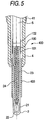
- a cylindrical outer pipe 403 may be provided instead as shown in Fig. 5 . With this configuration, the number of steps and cost in manufacturing the outer pipe can be reduced.
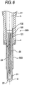
- an outer pipe 503 having an increasing diameter in a rear end side of the pipe may be provided as shown in Fig. 6 . With this configuration, the front end of the metal shell can be fixed to a boundary portion between a large diameter portion and a small diameter portion of the outer pipe, so that an outer pipe easy to position can be produced.
- Embodiment 1 has been described on the case where the heating portion 22 is embedded in the ceramic heater body 21 in the glow plug 1, the present invention is not limited thereto.
- the heating portion 22 may be exposed to an outer circumferential surface of the front end portion of the ceramic heater body 21.
Landscapes
- Engineering & Computer Science (AREA)
- Chemical & Material Sciences (AREA)
- Ceramic Engineering (AREA)
- Combustion & Propulsion (AREA)
- Mechanical Engineering (AREA)
- General Engineering & Computer Science (AREA)
- Resistance Heating (AREA)
Claims (5)
- Bougie de préchauffage (1) comprenant :un élément chauffant en céramique (2) en forme de tige incluant un corps d'élément chauffant en céramique (21) s'étendant axialement,une partie chauffante (22) intégrée dans une partie d'extrémité avant dudit corps d'élément chauffant en céramique (21) et apte à générer de la chaleur, lorsqu'on lui fournit de l'énergie, etdeux parties conductrices (23, 24) ayant chacune une extrémité reliée à ladite partie chauffante (22) et l'autre extrémité exposée à une surface circonférentielle extérieure d'une partie d'extrémité arrière du corps chauffant en céramique (21) ; un pôle central en forme de tige (5) s'étendant axialement de manière à être reliée électriquement à l'extérieur ;un tube extérieur (3) pour retenir l'élément chauffant en céramique (2), tandis que les parties d'extrémité avant et arrière dudit élément chauffant en céramique (2) font saillie dudit tube extérieur (3) ;une enveloppe en métal (4) pour entourer un côté d'extrémité avant dudit pôle central (5) tout en retenant le tube extérieur (3) ; etun organe cylindrique (100) incluant une partie d'extrémité avant reliée à une surface circonférentielle extérieure d'un côté d'extrémité arrière de l'élément chauffant en céramique (2), et une partie d'extrémité arrière reliée à une surface circonférentielle extérieure d'un côté d'extrémité avant du pôle central (5), ledit organe cylindrique (100) se composant d'un matériau métallique pour relier électriquement l'une des deux parties conductrices (23, 24) et le pôle central (5) entre elles,caractérisée en ce que l'organe cylindrique (100) a une dureté Vickers non inférieure à 200 HV à 25°C, etun organe élastique (6) disposé de manière à se trouver dans un espace entre le pôle central (5) et l'enveloppe en métal (4).
- Bougie de préchauffage telle que revendiquée dans la revendication 1, dans laquelle la partie d'extrémité avant de l'organe cylindrique (100) est reliée à la surface circonférentielle extérieure du côté d'extrémité arrière de l'élément chauffant en céramique (2) par ajustement serré.
- Bougie de préchauffage telle que revendiquée dans la revendication 2, dans laquelle l'ajustement serré est un ajustement à la presse.
- Bougie de préchauffage telle que revendiquée dans l'une quelconque des revendications 1 à 3, dans laquelle :ledit organe élastique (6) est en prise avec une surface arrière de l'enveloppe en métal (4) ; etla bougie de préchauffage comprend également un organe isolant cylindrique (7) disposé sur un côté d'extrémité arrière de l'organe élastique (6) de manière à presser ledit organe élastique (6).
- Bougie de préchauffage telle que revendiquée dans l'une quelconque des revendications 1 à 4, dans laquelle la partie d'extrémité arrière de l'organe cylindrique (100) est reliée à une surface circonférentielle extérieure d'un côté d'extrémité avant du pôle central (5) par soudage.
Applications Claiming Priority (2)
| Application Number | Priority Date | Filing Date | Title |
|---|---|---|---|
| JP2004043378 | 2004-02-19 | ||
| PCT/JP2005/002569 WO2005080877A1 (fr) | 2004-02-19 | 2005-02-18 | Bougie de préchauffage |
Publications (3)
| Publication Number | Publication Date |
|---|---|
| EP1719948A1 EP1719948A1 (fr) | 2006-11-08 |
| EP1719948A4 EP1719948A4 (fr) | 2017-01-25 |
| EP1719948B1 true EP1719948B1 (fr) | 2019-06-05 |
Family
ID=34879302
Family Applications (1)
| Application Number | Title | Priority Date | Filing Date |
|---|---|---|---|
| EP05710402.8A Active EP1719948B1 (fr) | 2004-02-19 | 2005-02-18 | Bougie de préchauffage |
Country Status (5)
| Country | Link |
|---|---|
| US (1) | US7420139B2 (fr) |
| EP (1) | EP1719948B1 (fr) |
| JP (1) | JP4536065B2 (fr) |
| CN (1) | CN1806147A (fr) |
| WO (1) | WO2005080877A1 (fr) |
Families Citing this family (12)
| Publication number | Priority date | Publication date | Assignee | Title |
|---|---|---|---|---|
| JP4968786B2 (ja) * | 2006-05-31 | 2012-07-04 | 日本特殊陶業株式会社 | グロープラグおよびその製造方法 |
| US20080299504A1 (en) * | 2007-06-01 | 2008-12-04 | Mark David Horn | Resonance driven glow plug torch igniter and ignition method |
| JP5188506B2 (ja) * | 2007-10-29 | 2013-04-24 | 京セラ株式会社 | セラミックヒータおよびこれを備えたグロープラグ |
| JP2009222274A (ja) * | 2008-03-14 | 2009-10-01 | Ngk Spark Plug Co Ltd | グロープラグ |
| JP5363475B2 (ja) * | 2008-12-25 | 2013-12-11 | 日本特殊陶業株式会社 | スパークプラグ |
| JP5425558B2 (ja) * | 2009-08-11 | 2014-02-26 | 日本特殊陶業株式会社 | グロープラグ用ハウジング及びグロープラグ |
| DE102010013333B4 (de) * | 2010-03-30 | 2012-05-24 | Borgwarner Beru Systems Gmbh | Glühkerze |
| KR101875621B1 (ko) * | 2012-04-09 | 2018-07-06 | 현대자동차 주식회사 | 글로우 플러그 및 이를 포함하는 전자식 써모스탯 |
| JP5858856B2 (ja) * | 2012-04-17 | 2016-02-10 | 日本特殊陶業株式会社 | グロープラグの製造方法 |
| JP5335974B2 (ja) * | 2012-07-06 | 2013-11-06 | 日本特殊陶業株式会社 | グロープラグ |
| KR101673102B1 (ko) * | 2012-08-08 | 2016-11-04 | 니혼도꾸슈도교 가부시키가이샤 | 글로 플러그 |
| KR20140142934A (ko) * | 2013-06-05 | 2014-12-15 | 우진공업주식회사 | 디젤 엔진용 글로우 플러그의 금구 및 그 제조 방법 |
Citations (1)
| Publication number | Priority date | Publication date | Assignee | Title |
|---|---|---|---|---|
| JP2003056848A (ja) * | 2001-08-13 | 2003-02-26 | Ngk Spark Plug Co Ltd | グロープラグ |
Family Cites Families (19)
| Publication number | Priority date | Publication date | Assignee | Title |
|---|---|---|---|---|
| DE8500986U1 (de) * | 1985-01-16 | 1985-04-25 | BERU Ruprecht GmbH & Co KG, 7140 Ludwigsburg | Glühkerze |
| JPS6325416A (ja) * | 1986-07-17 | 1988-02-02 | Ngk Spark Plug Co Ltd | セラミツクグロ−プラグ |
| JPH0942671A (ja) * | 1995-05-25 | 1997-02-14 | Denso Corp | セラミックグロープラグ及びその製造方法 |
| JP3861348B2 (ja) * | 1996-12-21 | 2006-12-20 | 株式会社デンソー | セラミックグロープラグ及びその製造方法 |
| DE10130488B4 (de) * | 2000-06-26 | 2011-07-21 | DENSO CORPORATION, Aichi-pref. | Glühkerze |
| JP4126854B2 (ja) * | 2000-06-26 | 2008-07-30 | 株式会社デンソー | グロープラグ |
| JP2002174423A (ja) * | 2000-09-26 | 2002-06-21 | Denso Corp | グロープラグ |
| JP3511602B2 (ja) * | 2000-09-29 | 2004-03-29 | 日本特殊陶業株式会社 | スパークプラグ |
| JP4073636B2 (ja) * | 2001-02-28 | 2008-04-09 | 日本特殊陶業株式会社 | スパークプラグ及びその製造方法 |
| JP2003051371A (ja) * | 2001-05-28 | 2003-02-21 | Ngk Spark Plug Co Ltd | ヒータ及びグロープラグ |
| JP4673503B2 (ja) * | 2001-06-07 | 2011-04-20 | 日本特殊陶業株式会社 | グロープラグ |
| JP4560249B2 (ja) * | 2001-08-13 | 2010-10-13 | 日本特殊陶業株式会社 | グロープラグ |
| JP4559671B2 (ja) * | 2001-08-28 | 2010-10-13 | 日本特殊陶業株式会社 | グロープラグ及びその製造方法 |
| JP2003130349A (ja) * | 2001-10-24 | 2003-05-08 | Denso Corp | グロープラグ |
| US7106167B2 (en) * | 2002-06-28 | 2006-09-12 | Heetronix | Stable high temperature sensor system with tungsten on AlN |
| JP2004134120A (ja) * | 2002-10-08 | 2004-04-30 | Denso Corp | スパークプラグ |
| JP3816073B2 (ja) * | 2003-01-28 | 2006-08-30 | 日本特殊陶業株式会社 | グロープラグ及びグロープラグの製造方法 |
| JP3942176B2 (ja) * | 2003-03-17 | 2007-07-11 | 日本特殊陶業株式会社 | 燃焼圧検知機能付きグロープラグ及びその製造方法 |
| EP1612486B1 (fr) * | 2004-06-29 | 2015-05-20 | Ngk Spark Plug Co., Ltd | Bougie à incandesence |
-
2005
- 2005-02-18 US US10/556,053 patent/US7420139B2/en active Active
- 2005-02-18 JP JP2006519349A patent/JP4536065B2/ja active Active
- 2005-02-18 CN CNA200580000475XA patent/CN1806147A/zh active Pending
- 2005-02-18 WO PCT/JP2005/002569 patent/WO2005080877A1/fr not_active Application Discontinuation
- 2005-02-18 EP EP05710402.8A patent/EP1719948B1/fr active Active
Patent Citations (1)
| Publication number | Priority date | Publication date | Assignee | Title |
|---|---|---|---|---|
| JP2003056848A (ja) * | 2001-08-13 | 2003-02-26 | Ngk Spark Plug Co Ltd | グロープラグ |
Also Published As
| Publication number | Publication date |
|---|---|
| EP1719948A1 (fr) | 2006-11-08 |
| EP1719948A4 (fr) | 2017-01-25 |
| US7420139B2 (en) | 2008-09-02 |
| JP4536065B2 (ja) | 2010-09-01 |
| CN1806147A (zh) | 2006-07-19 |
| WO2005080877A1 (fr) | 2005-09-01 |
| US20070056949A1 (en) | 2007-03-15 |
| JPWO2005080877A1 (ja) | 2007-10-25 |
Similar Documents
| Publication | Publication Date | Title |
|---|---|---|
| EP1719948B1 (fr) | Bougie de préchauffage | |
| EP1998595B1 (fr) | Corps de chauffe en ceramique et bougie de prechauffage | |
| EP1998596B1 (fr) | Corps de chauffe en ceramique et bougie de prechauffage | |
| JP4555508B2 (ja) | グロープラグ及びグロープラグの製造方法 | |
| JP4677140B2 (ja) | グロープラグ | |
| JP4093175B2 (ja) | グロープラグ | |
| EP1477740B1 (fr) | Dispositif de chauffage | |
| JP4559671B2 (ja) | グロープラグ及びその製造方法 | |
| JP4126854B2 (ja) | グロープラグ | |
| JP4562315B2 (ja) | セラミックヒータ、セラミックヒータの製造方法及びグロープラグ | |
| JP4425017B2 (ja) | ヒータ | |
| JP6668690B2 (ja) | セラミックグロープラグ | |
| JP4434516B2 (ja) | グロープラグ | |
| JP4560249B2 (ja) | グロープラグ | |
| JP2002364841A (ja) | グロープラグ | |
| JP4672910B2 (ja) | グロープラグの製造方法 | |
| JP4651227B2 (ja) | グロープラグ | |
| JP2005315474A (ja) | グロープラグ | |
| JP3810876B2 (ja) | ディーゼルエンジン用グロープラグ | |
| JP4596684B2 (ja) | グロープラグ | |
| JP2002115846A (ja) | グロープラグ | |
| JP4019004B2 (ja) | セラミックヒータ及びそれを用いたグロープラグ | |
| EP2472682A1 (fr) | Bougie d'allumage pour moteur à combustion interne et procédé de fabrication de celle-ci | |
| JP2007032878A (ja) | グロープラグおよびその製造方法 |
Legal Events
| Date | Code | Title | Description |
|---|---|---|---|
| PUAI | Public reference made under article 153(3) epc to a published international application that has entered the european phase |
Free format text: ORIGINAL CODE: 0009012 |
|
| 17P | Request for examination filed |
Effective date: 20051116 |
|
| AK | Designated contracting states |
Kind code of ref document: A1 Designated state(s): DE FR |
|
| DAX | Request for extension of the european patent (deleted) | ||
| RBV | Designated contracting states (corrected) |
Designated state(s): DE FR |
|
| RA4 | Supplementary search report drawn up and despatched (corrected) |
Effective date: 20170103 |
|
| RIC1 | Information provided on ipc code assigned before grant |
Ipc: H05B 3/14 20060101ALI20161221BHEP Ipc: F23Q 7/00 20060101AFI20161221BHEP |
|
| 17Q | First examination report despatched |
Effective date: 20180209 |
|
| GRAP | Despatch of communication of intention to grant a patent |
Free format text: ORIGINAL CODE: EPIDOSNIGR1 |
|
| INTG | Intention to grant announced |
Effective date: 20190102 |
|
| GRAS | Grant fee paid |
Free format text: ORIGINAL CODE: EPIDOSNIGR3 |
|
| GRAA | (expected) grant |
Free format text: ORIGINAL CODE: 0009210 |
|
| AK | Designated contracting states |
Kind code of ref document: B1 Designated state(s): DE FR |
|
| REG | Reference to a national code |
Ref country code: DE Ref legal event code: R096 Ref document number: 602005055875 Country of ref document: DE |
|
| REG | Reference to a national code |
Ref country code: DE Ref legal event code: R097 Ref document number: 602005055875 Country of ref document: DE |
|
| PLBE | No opposition filed within time limit |
Free format text: ORIGINAL CODE: 0009261 |
|
| STAA | Information on the status of an ep patent application or granted ep patent |
Free format text: STATUS: NO OPPOSITION FILED WITHIN TIME LIMIT |
|
| 26N | No opposition filed |
Effective date: 20200306 |
|
| PGFP | Annual fee paid to national office [announced via postgrant information from national office to epo] |
Ref country code: FR Payment date: 20210112 Year of fee payment: 17 |
|
| PG25 | Lapsed in a contracting state [announced via postgrant information from national office to epo] |
Ref country code: FR Free format text: LAPSE BECAUSE OF NON-PAYMENT OF DUE FEES Effective date: 20220228 |
|
| REG | Reference to a national code |
Ref country code: DE Ref legal event code: R081 Ref document number: 602005055875 Country of ref document: DE Owner name: NITERRA CO., LTD., NAGOYA-SHI, JP Free format text: FORMER OWNER: NGK SPARK PLUG CO., LTD., NAGOYA-SHI, AICHI-KEN, JP |
|
| PGFP | Annual fee paid to national office [announced via postgrant information from national office to epo] |
Ref country code: DE Payment date: 20231228 Year of fee payment: 20 |