EP1682288B1 - Verfahren und vorrichtung zum aufbringen einer regelbaren zugspannungsverteilung, insbesondere in den kantenbereichen kaltgewalzter metallbänder - Google Patents
Verfahren und vorrichtung zum aufbringen einer regelbaren zugspannungsverteilung, insbesondere in den kantenbereichen kaltgewalzter metallbänder Download PDFInfo
- Publication number
- EP1682288B1 EP1682288B1 EP04764552A EP04764552A EP1682288B1 EP 1682288 B1 EP1682288 B1 EP 1682288B1 EP 04764552 A EP04764552 A EP 04764552A EP 04764552 A EP04764552 A EP 04764552A EP 1682288 B1 EP1682288 B1 EP 1682288B1
- Authority
- EP
- European Patent Office
- Prior art keywords
- strip
- edge
- edges
- rolling
- tensile stress
- Prior art date
- Legal status (The legal status is an assumption and is not a legal conclusion. Google has not performed a legal analysis and makes no representation as to the accuracy of the status listed.)
- Expired - Lifetime
Links
- 238000000034 method Methods 0.000 title claims abstract description 29
- 238000009826 distribution Methods 0.000 title claims abstract description 13
- 229910052751 metal Inorganic materials 0.000 title claims abstract description 10
- 239000002184 metal Substances 0.000 title claims abstract description 10
- 239000007921 spray Substances 0.000 claims abstract description 20
- 238000001816 cooling Methods 0.000 claims abstract description 14
- 238000005097 cold rolling Methods 0.000 claims abstract description 10
- 239000000463 material Substances 0.000 claims abstract description 9
- 239000010731 rolling oil Substances 0.000 claims abstract description 8
- 238000005461 lubrication Methods 0.000 claims abstract description 5
- 238000004519 manufacturing process Methods 0.000 claims abstract description 4
- 238000005507 spraying Methods 0.000 claims abstract description 4
- 238000000926 separation method Methods 0.000 claims abstract description 3
- 238000009966 trimming Methods 0.000 claims abstract 2
- 239000000314 lubricant Substances 0.000 claims description 20
- 238000005096 rolling process Methods 0.000 claims description 20
- 230000001965 increasing effect Effects 0.000 claims description 8
- 239000002826 coolant Substances 0.000 claims description 7
- 238000010438 heat treatment Methods 0.000 claims description 5
- 239000000654 additive Substances 0.000 claims description 3
- 230000000996 additive effect Effects 0.000 claims description 3
- 230000001939 inductive effect Effects 0.000 claims description 3
- 239000010687 lubricating oil Substances 0.000 claims description 2
- 238000007493 shaping process Methods 0.000 claims description 2
- 230000001050 lubricating effect Effects 0.000 abstract description 5
- 238000006073 displacement reaction Methods 0.000 abstract description 2
- 239000011888 foil Substances 0.000 abstract description 2
- 239000000839 emulsion Substances 0.000 description 5
- XLYOFNOQVPJJNP-UHFFFAOYSA-N water Substances O XLYOFNOQVPJJNP-UHFFFAOYSA-N 0.000 description 5
- 238000001035 drying Methods 0.000 description 3
- 230000000694 effects Effects 0.000 description 3
- 239000006185 dispersion Substances 0.000 description 2
- 239000000835 fiber Substances 0.000 description 2
- CWYNVVGOOAEACU-UHFFFAOYSA-N Fe2+ Chemical compound [Fe+2] CWYNVVGOOAEACU-UHFFFAOYSA-N 0.000 description 1
- 206010065433 Ligament rupture Diseases 0.000 description 1
- 235000004443 Ricinus communis Nutrition 0.000 description 1
- 229910000831 Steel Inorganic materials 0.000 description 1
- 230000002411 adverse Effects 0.000 description 1
- 229910052782 aluminium Inorganic materials 0.000 description 1
- XAGFODPZIPBFFR-UHFFFAOYSA-N aluminium Chemical compound [Al] XAGFODPZIPBFFR-UHFFFAOYSA-N 0.000 description 1
- 230000000712 assembly Effects 0.000 description 1
- 238000000429 assembly Methods 0.000 description 1
- 239000002199 base oil Substances 0.000 description 1
- 235000013766 direct food additive Nutrition 0.000 description 1
- 239000000203 mixture Substances 0.000 description 1
- 239000003921 oil Substances 0.000 description 1
- 235000019476 oil-water mixture Nutrition 0.000 description 1
- 235000019198 oils Nutrition 0.000 description 1
- 230000035515 penetration Effects 0.000 description 1
- 230000000630 rising effect Effects 0.000 description 1
- 238000000638 solvent extraction Methods 0.000 description 1
- 239000010959 steel Substances 0.000 description 1
- 238000004781 supercooling Methods 0.000 description 1
- 238000005496 tempering Methods 0.000 description 1
- 238000007668 thin rolling process Methods 0.000 description 1
- 230000007704 transition Effects 0.000 description 1
Images


Classifications
-
- B—PERFORMING OPERATIONS; TRANSPORTING
- B21—MECHANICAL METAL-WORKING WITHOUT ESSENTIALLY REMOVING MATERIAL; PUNCHING METAL
- B21B—ROLLING OF METAL
- B21B37/00—Control devices or methods specially adapted for metal-rolling mills or the work produced thereby
- B21B37/28—Control of flatness or profile during rolling of strip, sheets or plates
-
- B—PERFORMING OPERATIONS; TRANSPORTING
- B21—MECHANICAL METAL-WORKING WITHOUT ESSENTIALLY REMOVING MATERIAL; PUNCHING METAL
- B21B—ROLLING OF METAL
- B21B37/00—Control devices or methods specially adapted for metal-rolling mills or the work produced thereby
- B21B37/28—Control of flatness or profile during rolling of strip, sheets or plates
- B21B37/30—Control of flatness or profile during rolling of strip, sheets or plates using roll camber control
- B21B37/32—Control of flatness or profile during rolling of strip, sheets or plates using roll camber control by cooling, heating or lubricating the rolls
-
- B—PERFORMING OPERATIONS; TRANSPORTING
- B21—MECHANICAL METAL-WORKING WITHOUT ESSENTIALLY REMOVING MATERIAL; PUNCHING METAL
- B21B—ROLLING OF METAL
- B21B45/00—Devices for surface or other treatment of work, specially combined with or arranged in, or specially adapted for use in connection with, metal-rolling mills
- B21B45/02—Devices for surface or other treatment of work, specially combined with or arranged in, or specially adapted for use in connection with, metal-rolling mills for lubricating, cooling, or cleaning
- B21B45/0203—Cooling
- B21B45/0209—Cooling devices, e.g. using gaseous coolants
-
- B—PERFORMING OPERATIONS; TRANSPORTING
- B21—MECHANICAL METAL-WORKING WITHOUT ESSENTIALLY REMOVING MATERIAL; PUNCHING METAL
- B21B—ROLLING OF METAL
- B21B45/00—Devices for surface or other treatment of work, specially combined with or arranged in, or specially adapted for use in connection with, metal-rolling mills
- B21B45/02—Devices for surface or other treatment of work, specially combined with or arranged in, or specially adapted for use in connection with, metal-rolling mills for lubricating, cooling, or cleaning
- B21B45/0269—Cleaning
- B21B45/0275—Cleaning devices
- B21B45/0278—Cleaning devices removing liquids
-
- B—PERFORMING OPERATIONS; TRANSPORTING
- B21—MECHANICAL METAL-WORKING WITHOUT ESSENTIALLY REMOVING MATERIAL; PUNCHING METAL
- B21B—ROLLING OF METAL
- B21B1/00—Metal-rolling methods or mills for making semi-finished products of solid or profiled cross-section; Sequence of operations in milling trains; Layout of rolling-mill plant, e.g. grouping of stands; Succession of passes or of sectional pass alternations
- B21B1/40—Metal-rolling methods or mills for making semi-finished products of solid or profiled cross-section; Sequence of operations in milling trains; Layout of rolling-mill plant, e.g. grouping of stands; Succession of passes or of sectional pass alternations for rolling foils which present special problems, e.g. because of thinness
-
- B—PERFORMING OPERATIONS; TRANSPORTING
- B21—MECHANICAL METAL-WORKING WITHOUT ESSENTIALLY REMOVING MATERIAL; PUNCHING METAL
- B21B—ROLLING OF METAL
- B21B13/00—Metal-rolling stands, i.e. an assembly composed of a stand frame, rolls, and accessories
- B21B13/14—Metal-rolling stands, i.e. an assembly composed of a stand frame, rolls, and accessories having counter-pressure devices acting on rolls to inhibit deflection of same under load; Back-up rolls
- B21B13/142—Metal-rolling stands, i.e. an assembly composed of a stand frame, rolls, and accessories having counter-pressure devices acting on rolls to inhibit deflection of same under load; Back-up rolls by axially shifting the rolls, e.g. rolls with tapered ends or with a curved contour for continuously-variable crown CVC
-
- B—PERFORMING OPERATIONS; TRANSPORTING
- B21—MECHANICAL METAL-WORKING WITHOUT ESSENTIALLY REMOVING MATERIAL; PUNCHING METAL
- B21B—ROLLING OF METAL
- B21B27/00—Rolls, roll alloys or roll fabrication; Lubricating, cooling or heating rolls while in use
- B21B27/06—Lubricating, cooling or heating rolls
- B21B27/10—Lubricating, cooling or heating rolls externally
- B21B2027/103—Lubricating, cooling or heating rolls externally cooling externally
-
- B—PERFORMING OPERATIONS; TRANSPORTING
- B21—MECHANICAL METAL-WORKING WITHOUT ESSENTIALLY REMOVING MATERIAL; PUNCHING METAL
- B21B—ROLLING OF METAL
- B21B27/00—Rolls, roll alloys or roll fabrication; Lubricating, cooling or heating rolls while in use
- B21B27/02—Shape or construction of rolls
-
- B—PERFORMING OPERATIONS; TRANSPORTING
- B21—MECHANICAL METAL-WORKING WITHOUT ESSENTIALLY REMOVING MATERIAL; PUNCHING METAL
- B21B—ROLLING OF METAL
- B21B27/00—Rolls, roll alloys or roll fabrication; Lubricating, cooling or heating rolls while in use
- B21B27/06—Lubricating, cooling or heating rolls
- B21B27/10—Lubricating, cooling or heating rolls externally
- B21B27/106—Heating the rolls
-
- B—PERFORMING OPERATIONS; TRANSPORTING
- B21—MECHANICAL METAL-WORKING WITHOUT ESSENTIALLY REMOVING MATERIAL; PUNCHING METAL
- B21B—ROLLING OF METAL
- B21B37/00—Control devices or methods specially adapted for metal-rolling mills or the work produced thereby
- B21B37/28—Control of flatness or profile during rolling of strip, sheets or plates
- B21B37/44—Control of flatness or profile during rolling of strip, sheets or plates using heating, lubricating or water-spray cooling of the product
-
- B—PERFORMING OPERATIONS; TRANSPORTING
- B21—MECHANICAL METAL-WORKING WITHOUT ESSENTIALLY REMOVING MATERIAL; PUNCHING METAL
- B21B—ROLLING OF METAL
- B21B39/00—Arrangements for moving, supporting, or positioning work, or controlling its movement, combined with or arranged in, or specially adapted for use in connection with, metal-rolling mills
- B21B39/02—Feeding or supporting work; Braking or tensioning arrangements, e.g. threading arrangements
- B21B39/08—Braking or tensioning arrangements
-
- B—PERFORMING OPERATIONS; TRANSPORTING
- B21—MECHANICAL METAL-WORKING WITHOUT ESSENTIALLY REMOVING MATERIAL; PUNCHING METAL
- B21B—ROLLING OF METAL
- B21B45/00—Devices for surface or other treatment of work, specially combined with or arranged in, or specially adapted for use in connection with, metal-rolling mills
- B21B45/02—Devices for surface or other treatment of work, specially combined with or arranged in, or specially adapted for use in connection with, metal-rolling mills for lubricating, cooling, or cleaning
- B21B45/0239—Lubricating
- B21B45/0245—Lubricating devices
- B21B45/0248—Lubricating devices using liquid lubricants, e.g. for sections, for tubes
- B21B45/0251—Lubricating devices using liquid lubricants, e.g. for sections, for tubes for strips, sheets, or plates
Definitions
- the invention relates to a method for applying a controllable tensile stress distribution, especially in the edge regions during cold rolling of metal strips, in order to reduce the risk of too high tensile structure and band edge cracks with the adverse consequence of production-reducing band breaks, and to improve the strip surface and its flatness even at relatively higher Tape speed and to reduce Bandbeklan, according to the preamble of claim 1 (see, eg JP-A-62142011 ).
- the invention also relates to an apparatus for carrying out the method, according to the preamble of claim 5.
- Process is collected before the nip and separated again. This makes it possible to produce the emulsion or dispersion, which is introduced into the nip, time and again with a certain concentration before moving into the nip.
- the focus of this invention is the actual production of the emulsion and the separation of the involved media.
- the document EP 1 188 494 A1 describes a belt scraper, belt scraper method, rolling mill and rolling method. To improve the productivity of a cold rolling device, this was provided with a belt scraper.
- the document EP 0 672 471 B1 discloses a method and apparatus for rolling ribbons.
- rollers wear-resistant at least in one of its end regions with enlarged radii running rollers are shifted from each other so that the rolled strip in its width in each case with areas of smaller radius in contact, and that with increasing heating and with thermal crowning by opposing displacement of the rollers Regions of their larger radius are pushed over edge regions of the rolled strip.
- edge area elevations of the strip which would occur due to the rising thermal crowning, are eliminated.
- the document DE 199 08 743 A1 discloses a method and an apparatus for drying and keeping dry, in particular cold strip in the outlet area of cold rolling and strip lines.
- drying and keeping dry particular of rolled strips it is known by a partitioning the dry area of the finished rolled strip from the wet room of Separate rolling stand.
- a non-contact seal between the foreclosure and the tape by an air cushion-like compressed gas cushion and a slit flow is proposed so as to apply compressed gas from a plurality of nozzles from Blasdüsenangn at right angles from above and below the tape surfaces. This measure prevents penetration of rolling oil or even emulsion at high belt speeds of over 1000 m / min, irrespective of the bandwidth, and achieves non-contact belt drying.
- the document DE 101 31 369 A1 discloses a method and apparatus for cooling and / or lubricating rolls, in particular the work rolls of a rolling stand and a rolled strip conveyed between and conveyed through these rolls, using water in the form of sprays as cooling medium and spray oil, oil-air mixture or oil -Water mixture, as a lubricant.
- a combined use of supercooling of the belt and roll surface and the roll lubrication on the scaffold inlet side is proposed by the two media - water or lubricant - the rolls or the strip fed separately and to different application sites of the rolling surface be applied.
- the European patent EP 0 672 471 B1 discloses a method and apparatus for rolling belts with axially displaceable rollers.
- the method is characterized in that low-wear, executed with at least at one of its end portions with enlarged radii rollers are shifted against each other such that the rolled strip is in its width in each case with areas of smaller radius in contact and that with increasing heating and with thermal crowning By oppositely moving the rollers and areas of the rollers with a larger radius are pushed over edge regions of the rolled strip.
- This method is used to counteract the annoying, thermal crowning effect simply and inexpensively, in order to make rolling plans more free.
- the U.S. Patent 5,943,896 discloses a method for influencing the contour of a rolled strip in the edge region.
- each work roll has a smaller diameter portion at one end than at the other end thereof, the smaller end portion being shorter than the large diameter portion across the width of the work roll.
- the diameter of the work roll linearly changes from the small diameter to the larger diameter.
- the two superposed rollers are arranged so that the thinner end of the one roller is opposite to the thicker end of the other roller.
- the Japanese godparent application JP 05050122 discloses an apparatus and method for realizing a sharply separated heat transfer between different temperature ranges on the surface of a work roll.
- the Japanese application 03297507 discloses a method for detecting the occurrence of stresses in the edge regions of a rolled strip and an extension to prevent the edge areas. For this purpose, it is proposed to apply a cold coolant in the region of the center of the rolled strip, that is to say not in its edge regions, and at the same time to apply a warm coolant in the edge regions and outside thereof.
- German patent application DE 31 144 87 A1 discloses a method and apparatus for roll tempering in cold rolling mills.
- a roll area which lies outside the strip edge and adjoins directly to the strip edge be tempered by applying heated lubricant.
- a relatively sharp borderline between hot and cold lubricant jet is set. The position of this boundary line should coincide with the position of the band edge.
- the invention is in the cold rolling, especially in the aluminum industry, but occasionally in the steel and non-ferrous metal area, the task of further reducing the resulting during thin rolling strip edges and near-edge long strip fibers and tape cracks on To further save edgebandings and thereby further improve the quality and quantity of application.
- This object is achieved by the method claimed in claim 1.
- This method is characterized in that the strip edges are influenced by "hot edge spray", in particular by zonewise spraying of rolling oil at different temperatures, and in the Work rolls in the Beriech the band edges a special finish is used, which is suitable for partial buildup of material in the prestretch, the material structure in subsequent stitches leads to a longer band edge and counteracts the risk of high Gebupes.
- An embodiment of the method according to claim 1 provides that an increased diameter decrease of the work rolls is made at the edge region due to partial increase in diameter during their shaping by means of inductive heating.
- the strip tension distribution is changed by a concave bendable or curved guide roller such that the tape tension is reduced at the strip edges and increased in the center of the strip.
- Another embodiment of the device advantageously includes a convexly bendable in the belt running direction or curved steering roller in an arrangement between two guide rollers for changing the tensile stress distribution of a strip before its entry into a rolling stand.
- the device is further configured by the fact that they are on the inlet side of a rolling mill means for direct additive application, in particular on the rolled strip z. B. for lubricating oil with relatively high viscosity, and on the outlet side of the work rolls means for bale cooling of the work rolls and preferably additional lubricant removal means which spray the rolled strip with preference from both the tape top and from the underside of the band with the attributable spray media.
- the device according to the invention has a device which removes coolant in the outlet side of the scaffold.
- FIG. 1 shows a part of a device for applying a controllable tensile stress distribution, in particular in edge regions during cold rolling of metal strips, with in at least two separate zones 10, 10 'existing spray nozzle assemblies 11, 11' with connections to separate Sprühstoffzu exiten 19, 19 'to different zones 10, 10th
- a partial inductive heating of the work roll in a conventional manner.
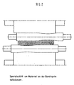
- FIG. 2 shows a pair of work rolls 12, 12 ', each having in one end a special grinding 13, 13' with increases in diameter in the end regions for extending the strip edges to be rolled with simultaneous reduction of tensile stresses and reduction of long strip fibers.
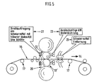
- FIG. 5 shows a side view of an inventive system, with a decoiler on the left side and a Aufrollhaspel on the right and guide means for the rolled strip 16 in the direction of belt 14 and means 21 for direct application of lubricant with viscosity or additive on the band inlet side and means 22 for bale cooling the outlet side work rolls and means 23 for the outlet side lubricant removal.
- a material build-up at the strip edge during the pre-stitching and correspondingly a material removal at the strip edge during the finishing passes is achieved with the aid of an additive direct application in the inlet side and roll cooling in the outlet side.
Landscapes
- Engineering & Computer Science (AREA)
- Mechanical Engineering (AREA)
- Physics & Mathematics (AREA)
- Geometry (AREA)
- Metal Rolling (AREA)
- Heat Treatment Of Strip Materials And Filament Materials (AREA)
Description
- Die Erfindung betrifft ein Verfahren zum Aufbringen einer regelbaren Zugspannungsverteilung, insbesondere in den Kantenbereichen beim Kaltwalzen von Metallbändern, zwecks Verringerung der Gefahr eines zu hohen Zugaufbaus und Bandkantenrissen mit der nachteiligen Folge von produktionsmindernden Bandrissen, sowie zur Verbesserung der Bandoberfläche und ihrer Planheit auch bei relativ höherer Bandlaufgeschwindigkeit und zur Reduzierung von Bandbesäumbreiten, gemäß dem Oberbegriff des Anspruchs 1 (siehe z.B.
JP-A-62142011 - Aus dem Dokument
EP 0 054 172 A2 ist ein Verfahren bekannt, bei dem zum spannungsfreien Walzen von Kaltband der Reibwert zwischen den Bandoberflächen und den Walzenballen-Mantelflächen durch Beaufschlagung mit Walzschmiermittel beeinflusst wird. Diese wird dabei in Abhängigkeit von hinter dem letzten Gerüst in Querrichtung des Bandes liegenden Zonen ermittelten partiellen Zugspannungen zugeführt. Dabei wird Grundöl dem Walzschmiermittel vor dem Einlauf des Bandes in den Walzspalt in durch die ermittelten partiellen Zugspannungen bestimmten Mengen und in örtlich begrenzten Bereichen unmittelbar auf die Bandoberflächen aufgetragen. Ziel dieser Maßnahme ist es, die Schmierbestandteile lokal auf Streifen des zu walzenden Bandes aufzubringen, um durch die lokal verbesserte Schmierung die dortige Walzkraft zu senken und damit auch die lokale Abplattung der Walze zu verringern. Weiterhin wird die in die Walze eingebrachte Reibungswärme an diesen Stellen reduziert. - Aus dem Dokument
EP 0 367 967 B1 ist ein Verfahren und eine Vorrichtung bekannt, bei der die Konzentration einer Emulsion aus Walzöl gezielt beeinflusst und die Emulsion bzw. Dispersion nach Austritt aus dem Walzspalt bzw. - Ablauf vor dem Walzspalt aufgefangen und wieder getrennt wird. Hiermit wird es möglich, die Emulsion bzw. Dispersion, die in den Walzspalt eingebracht wird, immer wieder mit bestimmter Konzentration zeitgerecht vor Einzug in den Walzspalt herzustellen. Der Schwerpunkt dieser Erfindung liegt in der aktuellen Herstellung der Emulsion und der Trennung der beteiligten Medien.
- Das Dokument
EP 1 188 494 A1 beschreibt eine Bandabstreifvorrichtung, Bandabstreifmethode, Walzgerüst und Walzverfahren. Zur Verbesserung der Produktivität einer Kaltwalzeinrichtung wurde diese mit einem Bandabstreifer versehen. - Beim Hochgeschwindigkeitswalzen von mehr als 700 m/min, welches mit konventionellen Abstreiferrollen oder Rohr-Abstreifer nicht ausführbar war, wurde die Produktivität der Kaltwalzeinrichtung und die Oberflächenqualität eines Bandes durch Hinzufügen der Abstreifvorrichtung wesentlich verbessert.
- Das Dokument
EP 0 672 471 B1 offenbart ein Verfahren und eine Vorrichtung zum Walzen von Bändern. Als Walzen werden verschleißarme, mit mindestens in einem ihrer Endbereiche mit vergrößerten Radien ausgeführte Walzen derart gegeneinander verschoben, dass das Walzband in seiner Breite jeweils mit Bereichen des geringeren Radius in Kontakt stehen, und dass mit zunehmender Erwärmung und mit thermischer Bombierung durch gegensinniges Verschieben der Walzen Bereiche ihres größeren Radius über Randbereiche des Walzbandes geschoben werden. Dadurch wird erreicht, dass die Randbereich-Überhöhungen des Bandes, die durch die steigende thermische Bombierung eintreten würden, beseitigt werden. - Das Dokument
DE 199 08 743 A1 offenbart ein Verfahren und eine Vorrichtung zum Trocknen und Trockenhalten von insbesondere Kaltband im Auslaufbereich von Kaltwalz- und Bandanlagen. Bei der Trocknung und dem Trockenhalten insbesondere von gewalzten Bändern ist es bekannt, durch eine Abschottung den Trockenbereich des fertiggewalzten Bandes vom Feuchtraum des Walzgerüstes zu trennen. Hierzu wird eine berührungslose Abdichtung zwischen der Abschottung und dem Band durch ein luftkissenähnliches Druckgaspolster sowie eine Spaltströmung vorgeschlagen, um so Druckgas aus einer Vielzahl von Blasdüsen aus Blasdüsenleisten im rechten Winkel von oben und unten auf die Bandoberflächen aufzubringen.
Durch diese Maßnahme wird auch bei hohen Bandgeschwindigkeiten über 1000 m/min unabhängig von der Bandbreite eine Durchdringung von Walzöl oder auch Emulsion mit Erfolg verhindert und eine berührungslose Bandtrocknung erreicht. - Das Dokument
DE 101 31 369 A1 offenbart ein Verfahren und eine Vorrichtung zum Kühlen und / oder Schmieren von Walzen, insbesondere der Arbeitswalzen eines Walzgerüstes und eines zwischen diesen Walzen gewalzten und hindurch geförderten Walzbandes unter Verwendung von Wasser in Form von Sprühstrahlen als Kühlmedium und Sprühöl, Öl-Luft-Gemisch oder Öl-WasserGemisch, als Schmiermittel. Zur Verbesserung der Schmier- und Kühlwirkung wird ein kombinierter Einsatz von Unterkühlung der Band- und Walzenoberfläche sowie der Walzenschmierung auf der Gerüsteinlaufseite vorgeschlagen, indem die beiden Medien - Wasser bzw. Schmiermittel - den Walzen bzw. dem Walzband getrennt zugeführt und an unterschiedliche Auftragsstellen der Walzoberfläche aufgetragen werden. Für Wasser bzw. Schmiermittel sind jeweils separate Vorratsbehälter sowie getrennte Zuführungen zu den Sprühbalken für Wasser und zu den Sprühbalken für das Schmiermittel vorgesehen. Mit großem Vorteil ergibt sich hieraus eine optimale Nutzung von jeweils Schmier- oder Kühlwirkung der beiden Medien Wasser und Schmiermittel und damit zugleich eine Senkung des Kraft- und Arbeitsbedarfes, bedingt durch minimierte Reibwerte an den Walzen. Die geschliffene Oberfläche der Walze hält selbst bei höchsten Beanspruchungen stand. Die bisher beobachteten Materialabschälungen an den Walzen werden unterbunden. Die Oberfläche des gewalzten Bandes bleibt optimal glatt, Zundereinschlüsse und Rattermarken auf der Bandoberfläche sind eliminiert. - Die europäische Patentschrift
EP 0 672 471 B1 offenbart ein Verfahren und eine Vorrichtung zum Walzen von Bändern, mit axial verschiebbaren Walzen. Das Verfahren ist dadurch gekennzeichnet, dass verschleißarme, mit mindestens an einem ihrer Endbereiche mit vergrößerten Radien ausgeführte Walzen derart gegeneinander verschoben werden, dass das Walzband in seiner Breite jeweils auch mit Bereichen mit geringerem Radius in Kontakt steht und dass mit zunehmender Erwärmung und mit thermischer Bombierung durch gegensinniges Verschieben der Walzen auch Bereiche der Walzen mit größerem Radius über Randbereiche des Walzbandes geschoben werden. Dieses Verfahren dient dazu, dem störenden, thermischen Bombierungseffekt einfach und kostengünstig entgegenzuwirken, um Walzpläne freier gestalten zu können. - Das
US Patent 5,943,896 offenbart ein Verfahren zum Beeinflussen der Kontur eines gewalzten Bandes im Randbereich. Für diesen Zweck wird vorgeschlagen, continuously variable crown CVC-Arbeitswalzen mit einem speziellen unsymmetrischen Schliff zu verwenden. Gemäß diesem Schliff weist jede Arbeitswalze an ihrem einen Ende einen Bereich mit einem kleineren Durchmesser auf als an ihrem anderen Ende, wobei der Bereich mit dem kleineren Ende über die Breite der Arbeitswalze gesehen, kürzer ist als der Bereich mit dem großen Durchmesser. In einem Übergangsbereich geht der Durchmesser der Arbeitswalze z.B. linear von dem kleinen Durchmesser auf den größeren Durchmesser über. Während des Walzbetriebs sind die beiden übereinander angeordneten Walzen so angeordnet, dass das dünnere Ende der einen Walze jeweils dem dickeren Ende der anderen Walze gegenüber steht. - Die japanische Patenanmeldung
JP 05050122 - Die japanische Anmeldung
03297507 - Die deutsche Offenlegungsschrift
DE 31 144 87 A1 offenbart ein Verfahren und eine Vorrichtung zur Walzentemperierung in Kaltwalzwerken. Um das Auftreten von hohen Kantenspannungen beim Walzen von Feinbändern und Folien zu vermeiden wird vorgeschlagen, dass ein Walzenbereich, der außerhalb der Bandkante liegt und sich unmittelbar an die Bandkante anschließt durch Aufbringen von erwärmtem Schmiermittel temperiert wird. Es wird eine relativ scharfe Grenzlinie zwischen warmem und kaltem Schmiermittelstrahl eingestellt. Die Lage dieser Grenzlinie soll mit der Lage der Bandkante zusammenfallen. - Schließlich ist es aus der gattungsbildenden japanischen Patentanmeldung
JP 62142011 - Ausgehend vom vorgenannten Stand der Technik liegt der Erfindung im Kaltwalzbereich, insbesondere in der Aluminium-Industrie, fallweise aber auch im Stahlbereich und NE-Metall-Bereich, die Aufgabe zugrunde, die beim Dünnwalzen entstehenden strammen Bandkanten und randnahen langen Bandfasern sowie Bandrisse weiter zu reduzieren, Besäumungen weiter einzusparen und dadurch die Qualität sowie die Quantität beim Ausbringen weiter zu verbessern.
- Diese Aufgabe wird durch das in Patentanspruch 1 beanspruchte Verfahren gelöst. Dieses Verfahren ist dadurch gekennzeichnet, dass die Bandkanten durch "Hot Edge Spray", insbesondere durch zonenweises Aufsprühen von Walzöl mit unterschiedlichen Temperaturen, beeinflusst werden und bei den Arbeitswalzen im Beriech der Bandkanten ein spezieller Schliff verwendet wird, der zum partiellen Materialaufbau beim Vorstich geeignet ist, wobei der Materialaufbau bei nachfolgenden Stichen zu einer längeren Bandkante führt und der Gefahr eines hohen Zugaufbaues entgegenwirkt.
- Mit Hilfe der erfindungsgemäßen Maßnahmen wird nachweisbar die Bandrissgefahr durch Bandkanteneinrisse deutlich verringert und zusätzlich die Bandoberfläche verbessert.
- Durch regelbare Zugspannungsverteilung, insbesondere im Bandkantenbereich wird ein höherer Materialdurchsatz unter Reduzierung von Nebenzeiten bei erhöhter Arbeitsgeschwindigkeit problemlos erreicht. Dazu werden insgesamt die Planheiten deutlich verbessert, die Produktion gesteigert und Walzöl-Umlaufmengen reduziert.
- Eine Ausgestaltung des Verfahrens nach Anspruch 1 sieht vor, dass eine vermehrte Durchmesserabnahme der Arbeitswalzen an den Kantenbereich infolge partieller Durchmessererhöhung während deren Formgebung mittels induktiver Erwärmung vorgenommen wird.
- Weiterhin kann von der Maßnahme Gebrauch gemacht sein, dass die Bandzugspannungsverteilung durch eine konkav biegbare bzw. gebogene Umlenkrolle derart geändert wird, dass die Bandzugspannung an den Bandkanten verringert und in der Bandmitte erhöht wird.
- Und schließlich kann von der weiteren Maßnahme Gebrauch gemacht sein, dass bei Vorstichen Material an den Bandkanten durch "Edge Sprays" mit Schmiermittel von relativ höherer Viskosität aufgebaut wird.
- Die oben genannte Aufgabe wird weiterhin durch eine Vorrichtung zum Aufbauen einer regelbaren Zugspannungsverteilung mit den Merkmalen des Anspruchs 5, gelöst. Die mit dieser Vorrichtung verbundenen Vorteile sind zuvor bei dem erfindungsgemäßen Verfahren beschrieben worden.
- Eine weitere Ausgestaltung der Vorrichtung beinhaltet vorteilhafterweise eine in Bandlaufrichtung konvex biegbare bzw. gebogene Lenkrolle in Anordnung zwischen zwei Führungsrollen zur Veränderung der Zugspannungsverteilung eines Bandes vor dessen Einlauf in ein Walzgerüst.
- In Ergänzung hierzu ist die Vorrichtung weiterhin dadurch ausgestaltet, dass sie auf der Einlaufseite eines Walzgerüstes Mittel zur Additiv-Direktauftragung, insbesondere auf das Walzband z. B. für Schmieröl mit relativ hoher Viskosität, und auf der Auslaufseite der Arbeitswalzen Mittel zur Ballenkühlung der Arbeitswalzen und bevorzugt zusätzliche Mittel zur Schmiermittelentfernung besitzt, die das Walzband mit Vorzug sowohl von der Bandoberseite als auch von der Bandunterseite her mit den zuordenbaren Sprühmedien besprühen.
- Und schließlich besitzt die Vorrichtung nach der Erfindung eine Einrichtung, welche Kühlmittel in der Auslaufseite des Gerüstes entfernt.
- Weitere Einzelheiten, Merkmale und Vorteile der Erfindung ergeben sich aus der nachstehenden Erläuterung eines in den Zeichnungen schematisch dargestellten Ausführungsbeispieles.
- Es zeigen:
- Figur 1
- eine Vorrichtung für "Hot Edge Spray" an der Walzenkante
- Figur 2
- einen Spezialschliff für Arbeitswalzen
- Figur 3
- In Seitenansicht eine konvex biegbare bzw. gebogene Lenkrolle
- Figur 4
- Die Draufsicht auf die Lenkrolle gem.
Fig. 3 - Figur 5
- In Seitenansicht eine erfindungsgemäße Anlage mit Direktauftragung von Schmiermittel auf das Walzband, auslaufseitiger Walzenkühlung und Schmiermittelentfernung.
-
Figur 1 zeigt einen Teil einer Vorrichtung zum Aufbringen einer regelbaren Zugspannungsverteilung, insbesondere in Kantenbereichen beim Kaltwalzen von Metallbändern, mit in wenigstens zwei getrennten Zonen 10, 10' vorhandenen Sprühdüsenanordnungen 11, 11' mit Anschlüssen an getrennte Sprühmittelzuführungen 19, 19' an unterschiedliche Zonen 10, 10' jeder Arbeitswalze 12. Darüber hinaus besteht die Möglichkeit einer partiellen induktiven Erwärmung der Arbeitswalze in an sich bekannter Art. -
Figur 2 zeigt ein Paar Arbeitswalzen 12, 12', die jeweils in einem Endbereich einen Spezialschliff 13, 13' mit Durchmesservergrößerungen in den Endbereichen zur Verlängerung der zu walzenden Bandkanten unter gleichzeitigem Abbau von Zugspannungen und Reduktion langer Bandfasern aufweisen. - Die
Figuren 3 und 4 zeigen gemeinsam in Seitenansicht und in Draufsicht eine Anordnung zur Verlängerung der Zugspannungsverteilung über die Bandbreite bei Fertigstichen. Dies wird erreicht durch einen variablen Umschlingungswinkel W bei Banddicken:1 - 6 µm mit W = 60 - 90 ° 8 - 20 µm mit W = 45 - 60 ° > 20 µm W = 45 ° und darüber bei Metallfolien W = 15 - 20 ° -
Figur 5 zeigt in Seitenansicht eine erfindungsgemäße Anlage, mit einer Abrollhaspel auf der linken Seite und einer Aufrollhaspel auf der rechten Seite sowie Führungsmittel für das Walzband 16 in Bandlaufrichtung 14 sowie Mittel 21 zur Direktauftragung von Schmiermittel mit Viskosität bzw. Additiv auf der Bandeinlaufseite sowie Mittel 22 zur Ballenkühlung der auslaufseitigen Arbeitswalzen und mit Mitteln 23 zur auslaufseitigen Schmiermittelentfernung. Damit wird ein Materialaufbau an der Bandkante während der Vorstiche und entsprechend ein Materialabbau an der Bandkante während der Fertigstiche mit Hilfe einer Additiv-Direktauftragung in der Einlaufseite und Walzenkühlung in der Auslaufseite erreicht. -
- 10, 10'
- Sprühzone
- 11, 11'
- Sprühdüsenanordnung
- 12, 12'
- Arbeitswalzen
- 14.
- Bandlaufrichtung
- 15.
- Lenkrolle
- 16.
- Band
- 17.
- Führungsrolle
- 19. 19'
- Sprühmittelzuführung
- 20.
- Walzgerüst
- 21.
- Additiv-Auftragung
- 22.
- Ballenkühlmittel
- 23.
- Schmiermittefentfernung
Claims (8)
- Verfahren zum Aufbringen einer regelbaren Zugspannungsverteilung, insbesondere in den Kantenbereichen beim Kaltwalzen von Metallbändern, zwecks Verringerung der Gefahr eines zu hohen Zugaufbaus und Bandkantenrissen mit der nachteiligen Folge von produktionsmindernden Bandrissen sowie zur Verbesserung der Bandoberfläche und ihrer Planheit auch bei relativ höherer Bandlaufgeschwindigkeit und zur Reduzierung von Bandbesäumbreiten, wobei das Verfahren folgenden Schritt umfasst:a) Trennen von Schmierung und Kühlung der Arbeitswalzen durch Schmieren an der Einlaufseite und Kühlen an der Auslaufseite, und weiterhin
gekennzeichnet ist durch
folgende zusätzliche Maßnahmen:b) Beeinflussung der Bandkanten durch "Hot Edge Spray", insbesondere durch zonenweises Aufsprühen von Walzöl mit unterschiedlichen Temperaturen, undc) Verwendung einer speziellen Schliffgestaltung der Arbeitswalzen im Bereich der Bandkanten zum partiellen Materialaufbau beim Vorstich, der bei nachfolgenden Stichen zu einer längeren Bandkante führt und der Gefahr eines hohen Zugspannungsaufbaus entgegenwirkt. - Verfahren nach Anspruch 1,
dadurch gekennzeichnet,
dass eine vermehrte Durchmesserabnahme der Arbeitswalzen an den Kantenbereichen infolge partieller Durchmessererhöhung während der Formgebung mittels induktiver Erwärmung vorgenommen wird. - Verfahren nach Anspruch 1 oder 2,
dadurch gekennzeichnet, - Verfahren nach einem oder mehreren der Ansprüche 1 bis 3,
dadurch gekennzeichnet,
dass bei Vorstichen Material an den Bandkanten durch "Edge Sprays" mit Schmiermittel mit relativ höherer Viskosität aufgebaut wird. - Vorrichtung zum Aufbauen einer regelbaren Zugspannungsverteilung, insbesondere in Kantenbereichen beim Kaltwalzen von Metallbändern, vorzugsweise zur Durchführung des Verfahrens nach den vorhergehenden Ansprüchen, wobei die Vorrichtung umfasst:mindestens eine Sprühdüsenanordnung (11, 11') an der Einlaufseite zum Aufbringen von Schmiermittel und ein Mittel zur Ballenkühlung der Arbeitswalze auf der Auslaufseite;durch gekennzeichnet
dass wenigstens zwei der Sprühdüsenanordnungen (11, 11') mit Anschlüssen für getrennte Sprühmittelzuführungen (19, 19') vorhanden sind zum Aufsprühen des Schmiermittels in Form von Walzöl mit unterschiedlichen Temperaturen auf unterschiedliche Zonen (10, 10') bei jeder Arbeitswalze (12) und;
dass die Arbeitswalzen (12, 12') jeweils einen Spezialschliff (13, 13') mit Durchmesservergrößerungen an ihren Endbereichen aufweisen zur Verlängerung der gewalzten Bandkanten bei gleichzeitigem Abbau von Zugspannungen und Reduktion langer Bandfasern in randnahen Bereichen der Bandkanten.
dass die Bandzugspannungsverteilung durch eine konkav biegbare bzw. gebogene Umlenkrolle derart geändert wird, dass die Bandzugspannung an den Bandkanten verringert und in der Bandmitte erhöht wird. - Vorrichtung nach Anspruch 5,
gekennzeichnet durch
eine in Bandlaufrichtung (14) konvex biegbare bzw. gebogene Lenkrolle (15) in Anordnung zwischen Führungsrollen (17) zur Veränderung der Zugspannungsverteilung eines Bandes (16) vor dessen Einlauf in ein Walzgerüst (20). - Vorrichtung nach Anspruch 5 oder 6,
dadurch gekennzeichnet,
dass sie auf der Einlaufseite eines Walzgerüstes (20) Mittel zur Additiv-Direktauftragung (21), insbesondere auf das Walzband (16), z. B. für Schmieröl mit relativ hoher Viskosität, und auf der Auslaufseite der Arbeitswalzen (12, 12') Mittel zur Ballenkühlung (22) der Arbeitswalzen und bevorzugt zusätzliche Mittel (23, 23') zur Schmiermittelentfernung besitzt, die das Walzband (16) mit Vorzug sowohl von der Bandoberseite als auch von der Bandunterseite her mit den zuordenbaren Sprühmedien besprühen. - Vorrichtung nach einem oder mehreren der Ansprüche 5 bis 7,
dadurch gekennzeichnet,
dass sie eine Einrichtung besitzt, welche Kühlmittel in der Auslaufseite des Gerüstes (20) entfernt.
Applications Claiming Priority (3)
| Application Number | Priority Date | Filing Date | Title |
|---|---|---|---|
| DE10340694 | 2003-09-04 | ||
| DE10352546A DE10352546A1 (de) | 2003-09-04 | 2003-11-11 | Verfahren und Vorrichtung zum Aufbringen einer regelbaren Zugspannungsverteilung, insbesondere in den Kantenbereichen kaltgewalzter Metallbänder |
| PCT/EP2004/009578 WO2005023444A2 (de) | 2003-09-04 | 2004-08-27 | Verfahren und vorrichtung zum aufbringen einer regelbaren zugspannungsverteilung, insbesondere in den kantenbereichen kaltgewalzter metallbänder |
Publications (2)
| Publication Number | Publication Date |
|---|---|
| EP1682288A2 EP1682288A2 (de) | 2006-07-26 |
| EP1682288B1 true EP1682288B1 (de) | 2009-06-17 |
Family
ID=34276536
Family Applications (1)
| Application Number | Title | Priority Date | Filing Date |
|---|---|---|---|
| EP04764552A Expired - Lifetime EP1682288B1 (de) | 2003-09-04 | 2004-08-27 | Verfahren und vorrichtung zum aufbringen einer regelbaren zugspannungsverteilung, insbesondere in den kantenbereichen kaltgewalzter metallbänder |
Country Status (14)
| Country | Link |
|---|---|
| US (1) | US7434435B2 (de) |
| EP (1) | EP1682288B1 (de) |
| JP (1) | JP4936889B2 (de) |
| KR (1) | KR101109459B1 (de) |
| CN (1) | CN1845803B (de) |
| AT (1) | ATE433809T1 (de) |
| BR (1) | BRPI0414152B1 (de) |
| CA (1) | CA2537501C (de) |
| DE (2) | DE10352546A1 (de) |
| ES (1) | ES2325539T3 (de) |
| RU (1) | RU2358820C2 (de) |
| TW (1) | TWI320726B (de) |
| WO (1) | WO2005023444A2 (de) |
| ZA (1) | ZA200601117B (de) |
Families Citing this family (23)
| Publication number | Priority date | Publication date | Assignee | Title |
|---|---|---|---|---|
| JP4355280B2 (ja) * | 2004-11-22 | 2009-10-28 | 新日本製鐵株式会社 | 冷間圧延における潤滑油供給方法 |
| DE102005042020A1 (de) * | 2005-09-02 | 2007-03-08 | Sms Demag Ag | Verfahren zum Schmieren und Kühlen von Walzen und Metallband beim Walzen, insbesondere beim Kaltwalzen, von Metallbändern |
| WO2008065893A1 (fr) * | 2006-11-27 | 2008-06-05 | Ihi Corporation | Appareil de laminage et procédé de contrôle de la forme d'une feuille laminée |
| DE102008015828A1 (de) * | 2007-09-26 | 2009-04-02 | Sms Demag Ag | Walzvorrichtung und Verfahren für deren Betrieb |
| JP5991292B2 (ja) * | 2012-09-24 | 2016-09-14 | Jfeスチール株式会社 | 鋼帯への塗油装置及び塗油方法 |
| JP6023563B2 (ja) * | 2012-11-19 | 2016-11-09 | アイシン精機株式会社 | ロール成形方法およびロール成形装置 |
| KR101763506B1 (ko) * | 2013-03-11 | 2017-07-31 | 노벨리스 인크. | 압연된 스트립의 평탄도의 개선 |
| CN105142813B (zh) | 2013-03-15 | 2017-04-05 | 诺维尔里斯公司 | 用于热金属辊轧中的定向冷却的制造方法和设备 |
| CN104942031B (zh) * | 2014-03-26 | 2017-05-31 | 宝山钢铁股份有限公司 | 一种冷轧轧制润滑剂供给方法 |
| CN104971949B (zh) * | 2014-04-10 | 2017-02-01 | 鞍钢股份有限公司 | 一种基于嵌入式计算机的冷轧带钢板形控制方法 |
| CA2947980C (en) * | 2014-05-09 | 2019-01-15 | Novelis Inc. | Hybrid oil and water cooled rolling |
| CA2998379C (en) | 2015-09-21 | 2020-01-21 | Novelis Inc. | Pre-heating and thermal control of work rolls in metal rolling processes and control systems thereof |
| EP3238843A1 (de) | 2016-04-29 | 2017-11-01 | Primetals Technologies Austria GmbH | Verfahren zum walzen eines walzgutes |
| CN108176717B (zh) * | 2017-12-28 | 2019-07-02 | 常熟市龙腾特种钢有限公司 | 一种热轧圆钢表面质量控制方法 |
| EP3599038A1 (de) * | 2018-07-25 | 2020-01-29 | Primetals Technologies Austria GmbH | Verfahren und vorrichtung zur ermittlung der seitlichen bandkontur eines laufenden metallbandes |
| JP7196341B2 (ja) * | 2020-01-29 | 2022-12-26 | Primetals Technologies Japan株式会社 | 圧延機及び金属板の圧延方法 |
| CN112216820A (zh) * | 2020-08-25 | 2021-01-12 | 合肥国轩高科动力能源有限公司 | 一种改善极片辊压反弹的方法及辊压装置 |
| CN113118215B (zh) * | 2021-04-16 | 2023-03-24 | 上海五星铜业股份有限公司 | 一种宽幅带箔轧制设备 |
| CN113118214B (zh) * | 2021-04-16 | 2023-03-24 | 上海五星铜业股份有限公司 | 一种轧制设备及轧制方法 |
| CN114472531B (zh) * | 2022-03-28 | 2023-05-26 | 河南鼎钰铝业有限公司 | 一种电极铝箔生产用精轧机 |
| CN116422698B (zh) * | 2023-06-13 | 2023-09-26 | 昆山精诚得精密五金模具有限公司 | 一种金属加工用冷轧机 |
| CN117161092B (zh) * | 2023-09-12 | 2024-06-28 | 江苏甬金金属科技有限公司 | 一种防应力变形的智能钢带轧制装置 |
| CN119239030B (zh) * | 2024-10-12 | 2025-05-16 | 鸡西哈工碳基材料科技有限公司 | 一种抗氧化柔性石墨纸生产用的压延装置 |
Family Cites Families (24)
| Publication number | Priority date | Publication date | Assignee | Title |
|---|---|---|---|---|
| US3802237A (en) * | 1972-05-26 | 1974-04-09 | United States Steel Corp | Localized strip shape control and display |
| JPS5841923B2 (ja) | 1979-07-25 | 1983-09-16 | 日本パ−カライジング株式会社 | 鋼板の清浄処理方法 |
| DE3235444A1 (de) * | 1982-09-24 | 1984-03-29 | Nihon Parkerizing Co. Ltd., Tokyo | Verfahren zur herstellung eines gereinigten kaltgewalzten stahlbandes |
| GB2156255A (en) * | 1984-03-23 | 1985-10-09 | Davy Mckee | Rolling mill |
| JPS6186003A (ja) | 1984-10-02 | 1986-05-01 | Nippon Steel Corp | ストリツプ圧延方法 |
| US4619126A (en) * | 1985-04-04 | 1986-10-28 | Atlantic Richfield Co. | Lubricant removal system for cold rolling stand |
| US4706480A (en) * | 1985-10-11 | 1987-11-17 | Svatos Joseph D | Rolling mill cooling system |
| JPS62142011A (ja) * | 1985-12-13 | 1987-06-25 | Ishikawajima Harima Heavy Ind Co Ltd | 板形状制御方法 |
| DE3614487A1 (de) * | 1986-04-29 | 1987-11-05 | Bbc Brown Boveri & Cie | Verfahren und vorrichtung zur walzentemperierung in kaltwalzwerken |
| JPH0280104A (ja) * | 1988-09-16 | 1990-03-20 | Nkk Corp | 洗浄ラインを備えた冷間圧延機による圧延方法 |
| JP2544003B2 (ja) * | 1990-04-17 | 1996-10-16 | 昭和アルミニウム株式会社 | 圧延薄板の形状制御方法 |
| US5212975A (en) * | 1991-05-13 | 1993-05-25 | International Rolling Mill Consultants, Inc. | Method and apparatus for cooling rolling mill rolls and flat rolled products |
| JPH04367308A (ja) * | 1991-06-11 | 1992-12-18 | Kobe Steel Ltd | 冷間圧延方法 |
| JPH0550122A (ja) * | 1991-08-21 | 1993-03-02 | Ishikawajima Harima Heavy Ind Co Ltd | 圧延ロールの熱クラウン制御装置 |
| US5165266A (en) * | 1991-11-04 | 1992-11-24 | International Rolling Mill Consultants, Inc. | Chockless roll support system |
| JPH06263300A (ja) * | 1993-03-09 | 1994-09-20 | Sumitomo Metal Ind Ltd | クラウンロール |
| DE4409299A1 (de) * | 1994-03-18 | 1995-09-21 | Schloemann Siemag Ag | Verfahren und Vorrichtung zum Walzen von Bändern |
| EP0776710B1 (de) * | 1995-11-20 | 2001-12-19 | SMS Demag AG | Vorrichtung zur Beeinflussung des Profils von gewalztem Walzband |
| DE19719318C2 (de) * | 1997-05-08 | 2003-06-12 | Sms Demag Ag | Verfahren zur Beeinflussung der Bandkontur im Kantenbereich eines Walzenbandes |
| FR2803548B1 (fr) * | 2000-01-10 | 2002-04-19 | Vai Clecim | Procede et dispositif de controle thermique du profil d'un cylindre dans un laminoir |
| EP1193004B1 (de) * | 2000-03-09 | 2006-08-23 | JFE Steel Corporation | Walzölversorgungsverfahren zum kaltwalzen |
| DE10043281B4 (de) * | 2000-04-08 | 2004-04-15 | ACHENBACH BUSCHHüTTEN GMBH | Walzenkühl- und/oder Schmiervorrichtung für Kaltbandwalzwerke, insbesondere Feinband- und Folienwalzwerke |
| JP2002210510A (ja) * | 2001-01-15 | 2002-07-30 | Mitsubishi Heavy Ind Ltd | 圧延ロールの誘導加熱装置および誘導加熱方法 |
| DE20106972U1 (de) * | 2001-04-23 | 2001-06-28 | Achenbach Buschhütten GmbH, 57223 Kreuztal | Walzenkühl- und/oder Schmiervorrichtung für Kaltbandwalzwerke, insbesondere Feinband- und Folienwalzwerke |
-
2003
- 2003-11-11 DE DE10352546A patent/DE10352546A1/de not_active Withdrawn
-
2004
- 2004-08-27 US US10/570,413 patent/US7434435B2/en not_active Expired - Fee Related
- 2004-08-27 AT AT04764552T patent/ATE433809T1/de active
- 2004-08-27 BR BRPI0414152A patent/BRPI0414152B1/pt not_active IP Right Cessation
- 2004-08-27 WO PCT/EP2004/009578 patent/WO2005023444A2/de not_active Ceased
- 2004-08-27 RU RU2006110636/02A patent/RU2358820C2/ru not_active IP Right Cessation
- 2004-08-27 KR KR1020067004434A patent/KR101109459B1/ko not_active Expired - Fee Related
- 2004-08-27 CA CA2537501A patent/CA2537501C/en not_active Expired - Fee Related
- 2004-08-27 ES ES04764552T patent/ES2325539T3/es not_active Expired - Lifetime
- 2004-08-27 JP JP2006525083A patent/JP4936889B2/ja not_active Expired - Fee Related
- 2004-08-27 DE DE502004009629T patent/DE502004009629D1/de not_active Expired - Lifetime
- 2004-08-27 EP EP04764552A patent/EP1682288B1/de not_active Expired - Lifetime
- 2004-08-27 CN CN2004800254233A patent/CN1845803B/zh not_active Expired - Fee Related
- 2004-08-31 TW TW093126157A patent/TWI320726B/zh not_active IP Right Cessation
-
2006
- 2006-02-08 ZA ZA200601117A patent/ZA200601117B/en unknown
Also Published As
| Publication number | Publication date |
|---|---|
| BRPI0414152A (pt) | 2006-10-31 |
| ATE433809T1 (de) | 2009-07-15 |
| US20070186609A1 (en) | 2007-08-16 |
| KR20060067967A (ko) | 2006-06-20 |
| DE502004009629D1 (de) | 2009-07-30 |
| WO2005023444A2 (de) | 2005-03-17 |
| ES2325539T3 (es) | 2009-09-08 |
| EP1682288A2 (de) | 2006-07-26 |
| JP4936889B2 (ja) | 2012-05-23 |
| TWI320726B (en) | 2010-02-21 |
| CN1845803A (zh) | 2006-10-11 |
| BRPI0414152B1 (pt) | 2015-10-20 |
| KR101109459B1 (ko) | 2012-01-31 |
| WO2005023444A3 (de) | 2006-01-26 |
| JP2007504007A (ja) | 2007-03-01 |
| RU2358820C2 (ru) | 2009-06-20 |
| US7434435B2 (en) | 2008-10-14 |
| ZA200601117B (en) | 2007-04-25 |
| CN1845803B (zh) | 2010-09-15 |
| RU2006110636A (ru) | 2006-08-10 |
| DE10352546A1 (de) | 2005-03-31 |
| CA2537501A1 (en) | 2005-03-17 |
| TW200520864A (en) | 2005-07-01 |
| CA2537501C (en) | 2010-10-19 |
Similar Documents
| Publication | Publication Date | Title |
|---|---|---|
| DE10352546A1 (de) | Verfahren und Vorrichtung zum Aufbringen einer regelbaren Zugspannungsverteilung, insbesondere in den Kantenbereichen kaltgewalzter Metallbänder | |
| DE19518144C2 (de) | Verfahren zum Herstellen von Warmband und kombinierte Stranggieß- und Warmwalz-Anlage | |
| EP0889762B1 (de) | Verfahren zur herstellung von warmgewalztem stahlband | |
| DE69411971T3 (de) | Warmwalzwerk für Stahlblech und Walzverfahren | |
| DE69202088T2 (de) | Vorrichtung und Verfahren zur Herstellung von warmgewalztem Stahl. | |
| EP1750864B2 (de) | Verfahren und vorrichtung zur kühlung und/oder schmierung von walzen und/oder walzgut | |
| EP3541564A1 (de) | Verfahren und vorrichtung zur herstellung eines kontinuierlichen bandförmigen verbundmaterials | |
| EP1399277A1 (de) | Verfahren und vorrichtung zum kühlen und schmieren von walzen eines walzgerüstes | |
| DE2526078B2 (de) | Walzenkühlvorrichtung für ein Quartowalzgerüst | |
| DE69315099T2 (de) | Tandemwalzsystem und Walzenschrägwalzwerk | |
| EP3658305B1 (de) | Walzgerüst mit einem gerüstkühler zum abkühlen eines stahlbands | |
| EP2934778B1 (de) | Vorrichtung zum kühlen von walzgut | |
| EP1365869B1 (de) | Walzgerüst zur herstellung planer walzbänder mit gewünschter bandprofilüberhöhung | |
| WO2003054236A1 (de) | Verfahren und einrichtung zum kontrollierten richten und kühlen von aus einem warmband-walzwerk auslaufendem breitem metallband, insbesondere von stahlband oder blech | |
| DE69607781T2 (de) | Warmbandwalzanlage | |
| EP3733317B1 (de) | Walzen eines walzguts | |
| DE60206851T2 (de) | Warmwalzwerk und warmwalzverfahren | |
| DE4025389C2 (de) | Gekühlte Förder- bzw. Niederhaltevorrichtung für eine Stauchpresse zur Breitenreduktion von Walzgut | |
| DE60004948T2 (de) | Verfahren zur kontinuierlichen herstellung eines metallbandes | |
| DE102020215769A1 (de) | Warmwalzgerüst für ein Warmwalzwerk und zum Herstellen eines metallenen Flachprodukts, Warmwalzwerk sowie Verfahren zum Betreiben eines Warmwalzwerks | |
| DE69109945T2 (de) | Umkehrbares Walzverfahren. | |
| EP0054172A2 (de) | Verfahren und Anordnung zum Walzen von spannungsfreiem Walzband | |
| DE68907728T2 (de) | Betrieb einer mehrstufigen walzanlage. | |
| EP2334448A2 (de) | Entzunderungsvorrichtung | |
| EP0998991A2 (de) | Betriebsverfahren für ein Walzgerüst einer Walzstrasse |
Legal Events
| Date | Code | Title | Description |
|---|---|---|---|
| PUAI | Public reference made under article 153(3) epc to a published international application that has entered the european phase |
Free format text: ORIGINAL CODE: 0009012 |
|
| 17P | Request for examination filed |
Effective date: 20060203 |
|
| AK | Designated contracting states |
Kind code of ref document: A2 Designated state(s): AT BE BG CH CY CZ DE DK EE ES FI FR GB GR HU IE IT LI LU MC NL PL PT RO SE SI SK TR |
|
| AX | Request for extension of the european patent |
Extension state: AL HR LT LV MK |
|
| DAX | Request for extension of the european patent (deleted) | ||
| GRAP | Despatch of communication of intention to grant a patent |
Free format text: ORIGINAL CODE: EPIDOSNIGR1 |
|
| GRAS | Grant fee paid |
Free format text: ORIGINAL CODE: EPIDOSNIGR3 |
|
| GRAA | (expected) grant |
Free format text: ORIGINAL CODE: 0009210 |
|
| AK | Designated contracting states |
Kind code of ref document: B1 Designated state(s): AT BE BG CH CY CZ DE DK EE ES FI FR GB GR HU IE IT LI LU MC NL PL PT RO SE SI SK TR |
|
| REG | Reference to a national code |
Ref country code: GB Ref legal event code: FG4D Free format text: NOT ENGLISH |
|
| REG | Reference to a national code |
Ref country code: CH Ref legal event code: EP |
|
| REG | Reference to a national code |
Ref country code: IE Ref legal event code: FG4D Free format text: LANGUAGE OF EP DOCUMENT: GERMAN |
|
| REF | Corresponds to: |
Ref document number: 502004009629 Country of ref document: DE Date of ref document: 20090730 Kind code of ref document: P |
|
| REG | Reference to a national code |
Ref country code: SE Ref legal event code: TRGR |
|
| REG | Reference to a national code |
Ref country code: ES Ref legal event code: FG2A Ref document number: 2325539 Country of ref document: ES Kind code of ref document: T3 |
|
| PG25 | Lapsed in a contracting state [announced via postgrant information from national office to epo] |
Ref country code: PL Free format text: LAPSE BECAUSE OF FAILURE TO SUBMIT A TRANSLATION OF THE DESCRIPTION OR TO PAY THE FEE WITHIN THE PRESCRIBED TIME-LIMIT Effective date: 20090617 Ref country code: SI Free format text: LAPSE BECAUSE OF FAILURE TO SUBMIT A TRANSLATION OF THE DESCRIPTION OR TO PAY THE FEE WITHIN THE PRESCRIBED TIME-LIMIT Effective date: 20090617 |
|
| REG | Reference to a national code |
Ref country code: IE Ref legal event code: FD4D |
|
| PG25 | Lapsed in a contracting state [announced via postgrant information from national office to epo] |
Ref country code: EE Free format text: LAPSE BECAUSE OF FAILURE TO SUBMIT A TRANSLATION OF THE DESCRIPTION OR TO PAY THE FEE WITHIN THE PRESCRIBED TIME-LIMIT Effective date: 20090617 Ref country code: RO Free format text: LAPSE BECAUSE OF FAILURE TO SUBMIT A TRANSLATION OF THE DESCRIPTION OR TO PAY THE FEE WITHIN THE PRESCRIBED TIME-LIMIT Effective date: 20090617 Ref country code: IE Free format text: LAPSE BECAUSE OF FAILURE TO SUBMIT A TRANSLATION OF THE DESCRIPTION OR TO PAY THE FEE WITHIN THE PRESCRIBED TIME-LIMIT Effective date: 20090617 |
|
| PG25 | Lapsed in a contracting state [announced via postgrant information from national office to epo] |
Ref country code: SK Free format text: LAPSE BECAUSE OF FAILURE TO SUBMIT A TRANSLATION OF THE DESCRIPTION OR TO PAY THE FEE WITHIN THE PRESCRIBED TIME-LIMIT Effective date: 20090617 |
|
| PG25 | Lapsed in a contracting state [announced via postgrant information from national office to epo] |
Ref country code: PT Free format text: LAPSE BECAUSE OF FAILURE TO SUBMIT A TRANSLATION OF THE DESCRIPTION OR TO PAY THE FEE WITHIN THE PRESCRIBED TIME-LIMIT Effective date: 20091017 Ref country code: BG Free format text: LAPSE BECAUSE OF FAILURE TO SUBMIT A TRANSLATION OF THE DESCRIPTION OR TO PAY THE FEE WITHIN THE PRESCRIBED TIME-LIMIT Effective date: 20090917 Ref country code: MC Free format text: LAPSE BECAUSE OF NON-PAYMENT OF DUE FEES Effective date: 20090831 |
|
| REG | Reference to a national code |
Ref country code: CH Ref legal event code: PL |
|
| PLBE | No opposition filed within time limit |
Free format text: ORIGINAL CODE: 0009261 |
|
| STAA | Information on the status of an ep patent application or granted ep patent |
Free format text: STATUS: NO OPPOSITION FILED WITHIN TIME LIMIT |
|
| PG25 | Lapsed in a contracting state [announced via postgrant information from national office to epo] |
Ref country code: DK Free format text: LAPSE BECAUSE OF FAILURE TO SUBMIT A TRANSLATION OF THE DESCRIPTION OR TO PAY THE FEE WITHIN THE PRESCRIBED TIME-LIMIT Effective date: 20090617 Ref country code: LI Free format text: LAPSE BECAUSE OF NON-PAYMENT OF DUE FEES Effective date: 20090831 Ref country code: CH Free format text: LAPSE BECAUSE OF NON-PAYMENT OF DUE FEES Effective date: 20090831 |
|
| 26N | No opposition filed |
Effective date: 20100318 |
|
| PG25 | Lapsed in a contracting state [announced via postgrant information from national office to epo] |
Ref country code: GR Free format text: LAPSE BECAUSE OF FAILURE TO SUBMIT A TRANSLATION OF THE DESCRIPTION OR TO PAY THE FEE WITHIN THE PRESCRIBED TIME-LIMIT Effective date: 20090918 |
|
| PGFP | Annual fee paid to national office [announced via postgrant information from national office to epo] |
Ref country code: ES Payment date: 20100823 Year of fee payment: 7 Ref country code: NL Payment date: 20100813 Year of fee payment: 7 |
|
| PGFP | Annual fee paid to national office [announced via postgrant information from national office to epo] |
Ref country code: CZ Payment date: 20100827 Year of fee payment: 7 Ref country code: FI Payment date: 20100812 Year of fee payment: 7 Ref country code: SE Payment date: 20100812 Year of fee payment: 7 |
|
| PGFP | Annual fee paid to national office [announced via postgrant information from national office to epo] |
Ref country code: BE Payment date: 20100810 Year of fee payment: 7 |
|
| PG25 | Lapsed in a contracting state [announced via postgrant information from national office to epo] |
Ref country code: LU Free format text: LAPSE BECAUSE OF NON-PAYMENT OF DUE FEES Effective date: 20090827 |
|
| PG25 | Lapsed in a contracting state [announced via postgrant information from national office to epo] |
Ref country code: HU Free format text: LAPSE BECAUSE OF FAILURE TO SUBMIT A TRANSLATION OF THE DESCRIPTION OR TO PAY THE FEE WITHIN THE PRESCRIBED TIME-LIMIT Effective date: 20091218 |
|
| PG25 | Lapsed in a contracting state [announced via postgrant information from national office to epo] |
Ref country code: TR Free format text: LAPSE BECAUSE OF FAILURE TO SUBMIT A TRANSLATION OF THE DESCRIPTION OR TO PAY THE FEE WITHIN THE PRESCRIBED TIME-LIMIT Effective date: 20090617 |
|
| PG25 | Lapsed in a contracting state [announced via postgrant information from national office to epo] |
Ref country code: CY Free format text: LAPSE BECAUSE OF FAILURE TO SUBMIT A TRANSLATION OF THE DESCRIPTION OR TO PAY THE FEE WITHIN THE PRESCRIBED TIME-LIMIT Effective date: 20090617 |
|
| BERE | Be: lapsed |
Owner name: SMS SIEMAG AG Effective date: 20110831 |
|
| REG | Reference to a national code |
Ref country code: NL Ref legal event code: V1 Effective date: 20120301 |
|
| REG | Reference to a national code |
Ref country code: SE Ref legal event code: EUG |
|
| PG25 | Lapsed in a contracting state [announced via postgrant information from national office to epo] |
Ref country code: CZ Free format text: LAPSE BECAUSE OF NON-PAYMENT OF DUE FEES Effective date: 20110827 |
|
| PG25 | Lapsed in a contracting state [announced via postgrant information from national office to epo] |
Ref country code: BE Free format text: LAPSE BECAUSE OF NON-PAYMENT OF DUE FEES Effective date: 20110831 Ref country code: FI Free format text: LAPSE BECAUSE OF NON-PAYMENT OF DUE FEES Effective date: 20110827 Ref country code: NL Free format text: LAPSE BECAUSE OF NON-PAYMENT OF DUE FEES Effective date: 20120301 |
|
| REG | Reference to a national code |
Ref country code: ES Ref legal event code: FD2A Effective date: 20121207 |
|
| PG25 | Lapsed in a contracting state [announced via postgrant information from national office to epo] |
Ref country code: ES Free format text: LAPSE BECAUSE OF NON-PAYMENT OF DUE FEES Effective date: 20110828 |
|
| PG25 | Lapsed in a contracting state [announced via postgrant information from national office to epo] |
Ref country code: SE Free format text: LAPSE BECAUSE OF NON-PAYMENT OF DUE FEES Effective date: 20110828 |
|
| REG | Reference to a national code |
Ref country code: DE Ref legal event code: R082 Ref document number: 502004009629 Country of ref document: DE Representative=s name: HEMMERICH & KOLLEGEN, DE Ref country code: DE Ref legal event code: R081 Ref document number: 502004009629 Country of ref document: DE Owner name: SMS GROUP GMBH, DE Free format text: FORMER OWNER: SMS SIEMAG AG, 40237 DUESSELDORF, DE |
|
| REG | Reference to a national code |
Ref country code: FR Ref legal event code: PLFP Year of fee payment: 13 |
|
| REG | Reference to a national code |
Ref country code: FR Ref legal event code: PLFP Year of fee payment: 14 |
|
| REG | Reference to a national code |
Ref country code: FR Ref legal event code: PLFP Year of fee payment: 15 |
|
| PGFP | Annual fee paid to national office [announced via postgrant information from national office to epo] |
Ref country code: DE Payment date: 20180823 Year of fee payment: 15 Ref country code: FR Payment date: 20180827 Year of fee payment: 15 Ref country code: IT Payment date: 20180830 Year of fee payment: 15 |
|
| PGFP | Annual fee paid to national office [announced via postgrant information from national office to epo] |
Ref country code: GB Payment date: 20180822 Year of fee payment: 15 Ref country code: AT Payment date: 20180822 Year of fee payment: 15 |
|
| REG | Reference to a national code |
Ref country code: DE Ref legal event code: R119 Ref document number: 502004009629 Country of ref document: DE |
|
| REG | Reference to a national code |
Ref country code: AT Ref legal event code: MM01 Ref document number: 433809 Country of ref document: AT Kind code of ref document: T Effective date: 20190827 |
|
| GBPC | Gb: european patent ceased through non-payment of renewal fee |
Effective date: 20190827 |
|
| PG25 | Lapsed in a contracting state [announced via postgrant information from national office to epo] |
Ref country code: AT Free format text: LAPSE BECAUSE OF NON-PAYMENT OF DUE FEES Effective date: 20190827 |
|
| PG25 | Lapsed in a contracting state [announced via postgrant information from national office to epo] |
Ref country code: DE Free format text: LAPSE BECAUSE OF NON-PAYMENT OF DUE FEES Effective date: 20200303 Ref country code: FR Free format text: LAPSE BECAUSE OF NON-PAYMENT OF DUE FEES Effective date: 20190831 |
|
| PG25 | Lapsed in a contracting state [announced via postgrant information from national office to epo] |
Ref country code: GB Free format text: LAPSE BECAUSE OF NON-PAYMENT OF DUE FEES Effective date: 20190827 Ref country code: IT Free format text: LAPSE BECAUSE OF NON-PAYMENT OF DUE FEES Effective date: 20190827 |