EP1644989B9 - Encapsulation de piles solaires - Google Patents
Encapsulation de piles solaires Download PDFInfo
- Publication number
- EP1644989B9 EP1644989B9 EP04741014A EP04741014A EP1644989B9 EP 1644989 B9 EP1644989 B9 EP 1644989B9 EP 04741014 A EP04741014 A EP 04741014A EP 04741014 A EP04741014 A EP 04741014A EP 1644989 B9 EP1644989 B9 EP 1644989B9
- Authority
- EP
- European Patent Office
- Prior art keywords
- solar cell
- encapsulant
- accordance
- cell module
- adhesive
- Prior art date
- Legal status (The legal status is an assumption and is not a legal conclusion. Google has not performed a legal analysis and makes no representation as to the accuracy of the status listed.)
- Revoked
Links
- 238000005538 encapsulation Methods 0.000 title claims abstract description 32
- 239000008393 encapsulating agent Substances 0.000 claims abstract description 177
- 238000000034 method Methods 0.000 claims abstract description 73
- 229920001296 polysiloxane Polymers 0.000 claims abstract description 73
- 239000007788 liquid Substances 0.000 claims abstract description 69
- 239000000203 mixture Substances 0.000 claims abstract description 61
- 230000008569 process Effects 0.000 claims abstract description 59
- 239000000758 substrate Substances 0.000 claims abstract description 49
- 239000003054 catalyst Substances 0.000 claims abstract description 31
- 125000003342 alkenyl group Chemical group 0.000 claims abstract description 22
- 125000004435 hydrogen atom Chemical group [H]* 0.000 claims abstract description 12
- 238000006459 hydrosilylation reaction Methods 0.000 claims abstract description 11
- 239000003431 cross linking reagent Substances 0.000 claims abstract description 8
- 239000001257 hydrogen Substances 0.000 claims abstract description 8
- 229910052739 hydrogen Inorganic materials 0.000 claims abstract description 8
- UFHFLCQGNIYNRP-UHFFFAOYSA-N Hydrogen Chemical compound [H][H] UFHFLCQGNIYNRP-UHFFFAOYSA-N 0.000 claims abstract description 7
- 229920002050 silicone resin Polymers 0.000 claims abstract description 7
- 229920005645 diorganopolysiloxane polymer Polymers 0.000 claims abstract description 6
- 230000001070 adhesive effect Effects 0.000 claims description 76
- 239000000853 adhesive Substances 0.000 claims description 74
- 239000010410 layer Substances 0.000 claims description 61
- 239000000463 material Substances 0.000 claims description 61
- 239000011521 glass Substances 0.000 claims description 57
- 235000012431 wafers Nutrition 0.000 claims description 48
- 239000012790 adhesive layer Substances 0.000 claims description 25
- 239000010409 thin film Substances 0.000 claims description 25
- 238000000576 coating method Methods 0.000 claims description 24
- 239000011248 coating agent Substances 0.000 claims description 23
- 125000004432 carbon atom Chemical group C* 0.000 claims description 20
- 239000013464 silicone adhesive Substances 0.000 claims description 17
- 239000002318 adhesion promoter Substances 0.000 claims description 13
- 125000000217 alkyl group Chemical group 0.000 claims description 12
- 229920005989 resin Polymers 0.000 claims description 12
- 239000011347 resin Substances 0.000 claims description 12
- 230000005540 biological transmission Effects 0.000 claims description 11
- 230000005855 radiation Effects 0.000 claims description 11
- BLRPTPMANUNPDV-UHFFFAOYSA-N Silane Chemical compound [SiH4] BLRPTPMANUNPDV-UHFFFAOYSA-N 0.000 claims description 10
- 239000003112 inhibitor Substances 0.000 claims description 10
- 229910000077 silane Inorganic materials 0.000 claims description 10
- 239000010408 film Substances 0.000 claims description 9
- 229910021419 crystalline silicon Inorganic materials 0.000 claims description 8
- 229910021420 polycrystalline silicon Inorganic materials 0.000 claims description 8
- 229910052710 silicon Inorganic materials 0.000 claims description 8
- 239000010703 silicon Substances 0.000 claims description 8
- 229920001169 thermoplastic Polymers 0.000 claims description 7
- 239000004416 thermosoftening plastic Substances 0.000 claims description 7
- NIXOWILDQLNWCW-UHFFFAOYSA-N acrylic acid group Chemical group C(C=C)(=O)O NIXOWILDQLNWCW-UHFFFAOYSA-N 0.000 claims description 6
- XLYOFNOQVPJJNP-UHFFFAOYSA-N water Substances O XLYOFNOQVPJJNP-UHFFFAOYSA-N 0.000 claims description 6
- 125000003545 alkoxy group Chemical group 0.000 claims description 5
- 229910052751 metal Inorganic materials 0.000 claims description 5
- 239000002184 metal Substances 0.000 claims description 5
- MARUHZGHZWCEQU-UHFFFAOYSA-N 5-phenyl-2h-tetrazole Chemical compound C1=CC=CC=C1C1=NNN=N1 MARUHZGHZWCEQU-UHFFFAOYSA-N 0.000 claims description 3
- JBRZTFJDHDCESZ-UHFFFAOYSA-N AsGa Chemical compound [As]#[Ga] JBRZTFJDHDCESZ-UHFFFAOYSA-N 0.000 claims description 3
- 229910001218 Gallium arsenide Inorganic materials 0.000 claims description 3
- KTSFMFGEAAANTF-UHFFFAOYSA-N [Cu].[Se].[Se].[In] Chemical compound [Cu].[Se].[Se].[In] KTSFMFGEAAANTF-UHFFFAOYSA-N 0.000 claims description 3
- HVMJUDPAXRRVQO-UHFFFAOYSA-N copper indium Chemical compound [Cu].[In] HVMJUDPAXRRVQO-UHFFFAOYSA-N 0.000 claims description 3
- ZZEMEJKDTZOXOI-UHFFFAOYSA-N digallium;selenium(2-) Chemical compound [Ga+3].[Ga+3].[Se-2].[Se-2].[Se-2] ZZEMEJKDTZOXOI-UHFFFAOYSA-N 0.000 claims description 3
- 238000000151 deposition Methods 0.000 claims 2
- 239000003795 chemical substances by application Substances 0.000 claims 1
- 230000008021 deposition Effects 0.000 claims 1
- 239000013536 elastomeric material Substances 0.000 claims 1
- 238000009501 film coating Methods 0.000 claims 1
- 229910021421 monocrystalline silicon Inorganic materials 0.000 claims 1
- 238000005507 spraying Methods 0.000 claims 1
- 239000003039 volatile agent Substances 0.000 claims 1
- 210000004027 cell Anatomy 0.000 description 196
- 230000003750 conditioning effect Effects 0.000 description 61
- BASFCYQUMIYNBI-UHFFFAOYSA-N platinum Chemical compound [Pt] BASFCYQUMIYNBI-UHFFFAOYSA-N 0.000 description 44
- -1 amorphous Chemical compound 0.000 description 39
- BFMKFCLXZSUVPI-UHFFFAOYSA-N ethyl but-3-enoate Chemical compound CCOC(=O)CC=C BFMKFCLXZSUVPI-UHFFFAOYSA-N 0.000 description 32
- 238000012360 testing method Methods 0.000 description 27
- 229910052697 platinum Inorganic materials 0.000 description 19
- 229920002620 polyvinyl fluoride Polymers 0.000 description 18
- 229920001577 copolymer Polymers 0.000 description 16
- 239000000654 additive Substances 0.000 description 15
- 230000032683 aging Effects 0.000 description 15
- 238000001723 curing Methods 0.000 description 13
- 238000003475 lamination Methods 0.000 description 12
- 239000004411 aluminium Substances 0.000 description 11
- 229910052782 aluminium Inorganic materials 0.000 description 11
- XAGFODPZIPBFFR-UHFFFAOYSA-N aluminium Chemical compound [Al] XAGFODPZIPBFFR-UHFFFAOYSA-N 0.000 description 11
- 238000010438 heat treatment Methods 0.000 description 11
- 230000032798 delamination Effects 0.000 description 10
- 125000002496 methyl group Chemical group [H]C([H])([H])* 0.000 description 10
- 230000004224 protection Effects 0.000 description 9
- URLKBWYHVLBVBO-UHFFFAOYSA-N Para-Xylene Chemical group CC1=CC=C(C)C=C1 URLKBWYHVLBVBO-UHFFFAOYSA-N 0.000 description 8
- XUIMIQQOPSSXEZ-UHFFFAOYSA-N Silicon Chemical compound [Si] XUIMIQQOPSSXEZ-UHFFFAOYSA-N 0.000 description 8
- 238000009432 framing Methods 0.000 description 8
- 238000004519 manufacturing process Methods 0.000 description 8
- 239000002904 solvent Substances 0.000 description 8
- 230000000007 visual effect Effects 0.000 description 8
- 238000009472 formulation Methods 0.000 description 7
- CSCPPACGZOOCGX-UHFFFAOYSA-N Acetone Chemical compound CC(C)=O CSCPPACGZOOCGX-UHFFFAOYSA-N 0.000 description 6
- KDLHZDBZIXYQEI-UHFFFAOYSA-N Palladium Chemical compound [Pd] KDLHZDBZIXYQEI-UHFFFAOYSA-N 0.000 description 6
- 238000005299 abrasion Methods 0.000 description 6
- 230000008859 change Effects 0.000 description 6
- 239000004205 dimethyl polysiloxane Substances 0.000 description 6
- 235000013870 dimethyl polysiloxane Nutrition 0.000 description 6
- QHSJIZLJUFMIFP-UHFFFAOYSA-N ethene;1,1,2,2-tetrafluoroethene Chemical group C=C.FC(F)=C(F)F QHSJIZLJUFMIFP-UHFFFAOYSA-N 0.000 description 6
- 229920000435 poly(dimethylsiloxane) Polymers 0.000 description 6
- 229920001843 polymethylhydrosiloxane Polymers 0.000 description 6
- 239000004065 semiconductor Substances 0.000 description 6
- 125000000391 vinyl group Chemical group [H]C([*])=C([H])[H] 0.000 description 6
- 229920002554 vinyl polymer Polymers 0.000 description 6
- CTQNGGLPUBDAKN-UHFFFAOYSA-N O-Xylene Chemical compound CC1=CC=CC=C1C CTQNGGLPUBDAKN-UHFFFAOYSA-N 0.000 description 5
- 229920006355 Tefzel Polymers 0.000 description 5
- 238000010924 continuous production Methods 0.000 description 5
- 125000000118 dimethyl group Chemical group [H]C([H])([H])* 0.000 description 5
- 238000002845 discoloration Methods 0.000 description 5
- 230000000694 effects Effects 0.000 description 5
- 150000002978 peroxides Chemical class 0.000 description 5
- 239000000243 solution Substances 0.000 description 5
- 238000003860 storage Methods 0.000 description 5
- 239000008096 xylene Substances 0.000 description 5
- 239000002253 acid Substances 0.000 description 4
- 230000000996 additive effect Effects 0.000 description 4
- 229910021417 amorphous silicon Inorganic materials 0.000 description 4
- 238000012512 characterization method Methods 0.000 description 4
- 150000001875 compounds Chemical class 0.000 description 4
- 238000007766 curtain coating Methods 0.000 description 4
- 230000007547 defect Effects 0.000 description 4
- 229920000840 ethylene tetrafluoroethylene copolymer Polymers 0.000 description 4
- 238000001125 extrusion Methods 0.000 description 4
- 239000003063 flame retardant Substances 0.000 description 4
- 125000001181 organosilyl group Chemical group [SiH3]* 0.000 description 4
- 239000000565 sealant Substances 0.000 description 4
- 239000007921 spray Substances 0.000 description 4
- 238000009736 wetting Methods 0.000 description 4
- LFQSCWFLJHTTHZ-UHFFFAOYSA-N Ethanol Chemical compound CCO LFQSCWFLJHTTHZ-UHFFFAOYSA-N 0.000 description 3
- LYCAIKOWRPUZTN-UHFFFAOYSA-N Ethylene glycol Chemical compound OCCO LYCAIKOWRPUZTN-UHFFFAOYSA-N 0.000 description 3
- KJTLSVCANCCWHF-UHFFFAOYSA-N Ruthenium Chemical compound [Ru] KJTLSVCANCCWHF-UHFFFAOYSA-N 0.000 description 3
- 229910020487 SiO3/2 Inorganic materials 0.000 description 3
- YXFVVABEGXRONW-UHFFFAOYSA-N Toluene Chemical compound CC1=CC=CC=C1 YXFVVABEGXRONW-UHFFFAOYSA-N 0.000 description 3
- 230000006750 UV protection Effects 0.000 description 3
- 230000008901 benefit Effects 0.000 description 3
- 230000015572 biosynthetic process Effects 0.000 description 3
- 238000006243 chemical reaction Methods 0.000 description 3
- 239000007795 chemical reaction product Substances 0.000 description 3
- 238000005260 corrosion Methods 0.000 description 3
- 230000007797 corrosion Effects 0.000 description 3
- 125000005388 dimethylhydrogensiloxy group Chemical group 0.000 description 3
- 230000005611 electricity Effects 0.000 description 3
- 238000005516 engineering process Methods 0.000 description 3
- 229920002313 fluoropolymer Polymers 0.000 description 3
- 239000004811 fluoropolymer Substances 0.000 description 3
- 229910052741 iridium Inorganic materials 0.000 description 3
- GKOZUEZYRPOHIO-UHFFFAOYSA-N iridium atom Chemical compound [Ir] GKOZUEZYRPOHIO-UHFFFAOYSA-N 0.000 description 3
- VLKZOEOYAKHREP-UHFFFAOYSA-N n-Hexane Chemical compound CCCCCC VLKZOEOYAKHREP-UHFFFAOYSA-N 0.000 description 3
- 229910052763 palladium Inorganic materials 0.000 description 3
- 230000000704 physical effect Effects 0.000 description 3
- 229920003023 plastic Polymers 0.000 description 3
- 239000004033 plastic Substances 0.000 description 3
- 229920000642 polymer Polymers 0.000 description 3
- 229920006254 polymer film Polymers 0.000 description 3
- 230000001681 protective effect Effects 0.000 description 3
- 230000009467 reduction Effects 0.000 description 3
- 229910052703 rhodium Inorganic materials 0.000 description 3
- 239000010948 rhodium Substances 0.000 description 3
- MHOVAHRLVXNVSD-UHFFFAOYSA-N rhodium atom Chemical compound [Rh] MHOVAHRLVXNVSD-UHFFFAOYSA-N 0.000 description 3
- 229910052707 ruthenium Inorganic materials 0.000 description 3
- 239000003566 sealing material Substances 0.000 description 3
- 230000035882 stress Effects 0.000 description 3
- 238000005382 thermal cycling Methods 0.000 description 3
- 125000000725 trifluoropropyl group Chemical group [H]C([H])(*)C([H])([H])C(F)(F)F 0.000 description 3
- 239000002699 waste material Substances 0.000 description 3
- YEOKHIZZKRRJKP-UHFFFAOYSA-N 1,2-bis(triethoxysilyl)ethane-1,2-diol Chemical compound C(C)O[Si](OCC)(OCC)C(C([Si](OCC)(OCC)OCC)O)O YEOKHIZZKRRJKP-UHFFFAOYSA-N 0.000 description 2
- MGTZNGICWXYDPR-ZJWHSJSFSA-N 3-[[(2r)-2-[[(2s)-2-(azepane-1-carbonylamino)-4-methylpentanoyl]amino]-3-(1h-indol-3-yl)propanoyl]amino]butanoic acid Chemical compound N([C@@H](CC(C)C)C(=O)N[C@H](CC=1C2=CC=CC=C2NC=1)C(=O)NC(C)CC(O)=O)C(=O)N1CCCCCC1 MGTZNGICWXYDPR-ZJWHSJSFSA-N 0.000 description 2
- HVAUBXAKLFNFFB-UHFFFAOYSA-N 3-ethylhex-1-yn-1-ol Chemical compound CCCC(CC)C#CO HVAUBXAKLFNFFB-UHFFFAOYSA-N 0.000 description 2
- 239000004971 Cross linker Substances 0.000 description 2
- KFZMGEQAYNKOFK-UHFFFAOYSA-N Isopropanol Chemical compound CC(C)O KFZMGEQAYNKOFK-UHFFFAOYSA-N 0.000 description 2
- 229910020388 SiO1/2 Inorganic materials 0.000 description 2
- 229910020447 SiO2/2 Inorganic materials 0.000 description 2
- 229910020485 SiO4/2 Inorganic materials 0.000 description 2
- GWEVSGVZZGPLCZ-UHFFFAOYSA-N Titan oxide Chemical compound O=[Ti]=O GWEVSGVZZGPLCZ-UHFFFAOYSA-N 0.000 description 2
- 238000009825 accumulation Methods 0.000 description 2
- 238000013006 addition curing Methods 0.000 description 2
- 125000003118 aryl group Chemical group 0.000 description 2
- 230000004888 barrier function Effects 0.000 description 2
- ZPOLOEWJWXZUSP-WAYWQWQTSA-N bis(prop-2-enyl) (z)-but-2-enedioate Chemical compound C=CCOC(=O)\C=C/C(=O)OCC=C ZPOLOEWJWXZUSP-WAYWQWQTSA-N 0.000 description 2
- 229910052799 carbon Inorganic materials 0.000 description 2
- 238000005266 casting Methods 0.000 description 2
- 239000003060 catalysis inhibitor Substances 0.000 description 2
- 238000006555 catalytic reaction Methods 0.000 description 2
- 238000005229 chemical vapour deposition Methods 0.000 description 2
- 238000011437 continuous method Methods 0.000 description 2
- 229920001971 elastomer Polymers 0.000 description 2
- 230000007613 environmental effect Effects 0.000 description 2
- 125000001495 ethyl group Chemical group [H]C([H])([H])C([H])([H])* 0.000 description 2
- 238000011065 in-situ storage Methods 0.000 description 2
- 238000010030 laminating Methods 0.000 description 2
- 230000005923 long-lasting effect Effects 0.000 description 2
- 230000007774 longterm Effects 0.000 description 2
- 238000002161 passivation Methods 0.000 description 2
- 125000001997 phenyl group Chemical group [H]C1=C([H])C([H])=C(*)C([H])=C1[H] 0.000 description 2
- 239000000049 pigment Substances 0.000 description 2
- 229920000139 polyethylene terephthalate Polymers 0.000 description 2
- 239000005020 polyethylene terephthalate Substances 0.000 description 2
- 229920002635 polyurethane Polymers 0.000 description 2
- 239000004814 polyurethane Substances 0.000 description 2
- 238000004886 process control Methods 0.000 description 2
- 230000002035 prolonged effect Effects 0.000 description 2
- 125000001436 propyl group Chemical group [H]C([*])([H])C([H])([H])C([H])([H])[H] 0.000 description 2
- 238000010107 reaction injection moulding Methods 0.000 description 2
- 230000002829 reductive effect Effects 0.000 description 2
- 230000000717 retained effect Effects 0.000 description 2
- 239000002689 soil Substances 0.000 description 2
- 239000007787 solid Substances 0.000 description 2
- 238000004544 sputter deposition Methods 0.000 description 2
- 229910001220 stainless steel Inorganic materials 0.000 description 2
- 239000010935 stainless steel Substances 0.000 description 2
- QQQSFSZALRVCSZ-UHFFFAOYSA-N triethoxysilane Chemical compound CCO[SiH](OCC)OCC QQQSFSZALRVCSZ-UHFFFAOYSA-N 0.000 description 2
- RIOQSEWOXXDEQQ-UHFFFAOYSA-N triphenylphosphine Chemical compound C1=CC=CC=C1P(C=1C=CC=CC=1)C1=CC=CC=C1 RIOQSEWOXXDEQQ-UHFFFAOYSA-N 0.000 description 2
- 238000010977 unit operation Methods 0.000 description 2
- WRXCBRHBHGNNQA-UHFFFAOYSA-N (2,4-dichlorobenzoyl) 2,4-dichlorobenzenecarboperoxoate Chemical compound ClC1=CC(Cl)=CC=C1C(=O)OOC(=O)C1=CC=C(Cl)C=C1Cl WRXCBRHBHGNNQA-UHFFFAOYSA-N 0.000 description 1
- PRBHEGAFLDMLAL-UHFFFAOYSA-N 1,5-Hexadiene Natural products CC=CCC=C PRBHEGAFLDMLAL-UHFFFAOYSA-N 0.000 description 1
- QYLFHLNFIHBCPR-UHFFFAOYSA-N 1-ethynylcyclohexan-1-ol Chemical compound C#CC1(O)CCCCC1 QYLFHLNFIHBCPR-UHFFFAOYSA-N 0.000 description 1
- VMAWODUEPLAHOE-UHFFFAOYSA-N 2,4,6,8-tetrakis(ethenyl)-2,4,6,8-tetramethyl-1,3,5,7,2,4,6,8-tetraoxatetrasilocane Chemical compound C=C[Si]1(C)O[Si](C)(C=C)O[Si](C)(C=C)O[Si](C)(C=C)O1 VMAWODUEPLAHOE-UHFFFAOYSA-N 0.000 description 1
- STMDPCBYJCIZOD-UHFFFAOYSA-N 2-(2,4-dinitroanilino)-4-methylpentanoic acid Chemical compound CC(C)CC(C(O)=O)NC1=CC=C([N+]([O-])=O)C=C1[N+]([O-])=O STMDPCBYJCIZOD-UHFFFAOYSA-N 0.000 description 1
- XMNIXWIUMCBBBL-UHFFFAOYSA-N 2-(2-phenylpropan-2-ylperoxy)propan-2-ylbenzene Chemical compound C=1C=CC=CC=1C(C)(C)OOC(C)(C)C1=CC=CC=C1 XMNIXWIUMCBBBL-UHFFFAOYSA-N 0.000 description 1
- CEBKHWWANWSNTI-UHFFFAOYSA-N 2-methylbut-3-yn-2-ol Chemical compound CC(C)(O)C#C CEBKHWWANWSNTI-UHFFFAOYSA-N 0.000 description 1
- KSLSOBUAIFEGLT-UHFFFAOYSA-N 2-phenylbut-3-yn-2-ol Chemical compound C#CC(O)(C)C1=CC=CC=C1 KSLSOBUAIFEGLT-UHFFFAOYSA-N 0.000 description 1
- 125000003903 2-propenyl group Chemical group [H]C([*])([H])C([H])=C([H])[H] 0.000 description 1
- NECRQCBKTGZNMH-UHFFFAOYSA-N 3,5-dimethylhex-1-yn-3-ol Chemical compound CC(C)CC(C)(O)C#C NECRQCBKTGZNMH-UHFFFAOYSA-N 0.000 description 1
- LAKYCCVWZNCNIO-UHFFFAOYSA-N 3-methylidenepent-1-yne Chemical compound CCC(=C)C#C LAKYCCVWZNCNIO-UHFFFAOYSA-N 0.000 description 1
- 239000004342 Benzoyl peroxide Substances 0.000 description 1
- OMPJBNCRMGITSC-UHFFFAOYSA-N Benzoylperoxide Chemical compound C=1C=CC=CC=1C(=O)OOC(=O)C1=CC=CC=C1 OMPJBNCRMGITSC-UHFFFAOYSA-N 0.000 description 1
- CURLTUGMZLYLDI-UHFFFAOYSA-N Carbon dioxide Chemical compound O=C=O CURLTUGMZLYLDI-UHFFFAOYSA-N 0.000 description 1
- 229920003345 Elvax® Polymers 0.000 description 1
- 101000969770 Homo sapiens Myelin protein zero-like protein 2 Proteins 0.000 description 1
- NTIZESTWPVYFNL-UHFFFAOYSA-N Methyl isobutyl ketone Chemical compound CC(C)CC(C)=O NTIZESTWPVYFNL-UHFFFAOYSA-N 0.000 description 1
- UIHCLUNTQKBZGK-UHFFFAOYSA-N Methyl isobutyl ketone Natural products CCC(C)C(C)=O UIHCLUNTQKBZGK-UHFFFAOYSA-N 0.000 description 1
- 102100021272 Myelin protein zero-like protein 2 Human genes 0.000 description 1
- KWYHDKDOAIKMQN-UHFFFAOYSA-N N,N,N',N'-tetramethylethylenediamine Chemical compound CN(C)CCN(C)C KWYHDKDOAIKMQN-UHFFFAOYSA-N 0.000 description 1
- OAICVXFJPJFONN-UHFFFAOYSA-N Phosphorus Chemical compound [P] OAICVXFJPJFONN-UHFFFAOYSA-N 0.000 description 1
- 239000004642 Polyimide Substances 0.000 description 1
- 229910052581 Si3N4 Inorganic materials 0.000 description 1
- NINIDFKCEFEMDL-UHFFFAOYSA-N Sulfur Chemical compound [S] NINIDFKCEFEMDL-UHFFFAOYSA-N 0.000 description 1
- 239000005864 Sulphur Substances 0.000 description 1
- 239000004809 Teflon Substances 0.000 description 1
- 229920006362 Teflon® Polymers 0.000 description 1
- 230000001476 alcoholic effect Effects 0.000 description 1
- 150000001298 alcohols Chemical class 0.000 description 1
- 150000001336 alkenes Chemical class 0.000 description 1
- 125000002947 alkylene group Chemical group 0.000 description 1
- PNEYBMLMFCGWSK-UHFFFAOYSA-N aluminium oxide Inorganic materials [O-2].[O-2].[O-2].[Al+3].[Al+3] PNEYBMLMFCGWSK-UHFFFAOYSA-N 0.000 description 1
- 238000013459 approach Methods 0.000 description 1
- 239000003849 aromatic solvent Substances 0.000 description 1
- 238000003491 array Methods 0.000 description 1
- QVGXLLKOCUKJST-UHFFFAOYSA-N atomic oxygen Chemical compound [O] QVGXLLKOCUKJST-UHFFFAOYSA-N 0.000 description 1
- 238000010923 batch production Methods 0.000 description 1
- QRUDEWIWKLJBPS-UHFFFAOYSA-N benzotriazole Chemical compound C1=CC=C2N[N][N]C2=C1 QRUDEWIWKLJBPS-UHFFFAOYSA-N 0.000 description 1
- 239000012964 benzotriazole Substances 0.000 description 1
- 235000019400 benzoyl peroxide Nutrition 0.000 description 1
- 230000005587 bubbling Effects 0.000 description 1
- 230000003139 buffering effect Effects 0.000 description 1
- 239000013590 bulk material Substances 0.000 description 1
- RSLWZZXJRRZAOD-UHFFFAOYSA-N but-1-en-3-yn-2-ylbenzene Chemical compound C#CC(=C)C1=CC=CC=C1 RSLWZZXJRRZAOD-UHFFFAOYSA-N 0.000 description 1
- 230000004956 cell adhesive effect Effects 0.000 description 1
- 239000012707 chemical precursor Substances 0.000 description 1
- 238000004140 cleaning Methods 0.000 description 1
- 230000000052 comparative effect Effects 0.000 description 1
- 230000001143 conditioned effect Effects 0.000 description 1
- 230000008602 contraction Effects 0.000 description 1
- 238000004132 cross linking Methods 0.000 description 1
- 239000013078 crystal Substances 0.000 description 1
- 125000004122 cyclic group Chemical group 0.000 description 1
- 238000013016 damping Methods 0.000 description 1
- 230000003247 decreasing effect Effects 0.000 description 1
- 230000001627 detrimental effect Effects 0.000 description 1
- 239000000428 dust Substances 0.000 description 1
- 238000007688 edging Methods 0.000 description 1
- 239000000806 elastomer Substances 0.000 description 1
- FWDBOZPQNFPOLF-UHFFFAOYSA-N ethenyl(triethoxy)silane Chemical compound CCO[Si](OCC)(OCC)C=C FWDBOZPQNFPOLF-UHFFFAOYSA-N 0.000 description 1
- KPWVUBSQUODFPP-UHFFFAOYSA-N ethenyl-(ethenyl-methyl-phenylsilyl)oxy-methyl-phenylsilane Chemical compound C=1C=CC=CC=1[Si](C)(C=C)O[Si](C)(C=C)C1=CC=CC=C1 KPWVUBSQUODFPP-UHFFFAOYSA-N 0.000 description 1
- BITPLIXHRASDQB-UHFFFAOYSA-N ethenyl-[ethenyl(dimethyl)silyl]oxy-dimethylsilane Chemical compound C=C[Si](C)(C)O[Si](C)(C)C=C BITPLIXHRASDQB-UHFFFAOYSA-N 0.000 description 1
- 239000005038 ethylene vinyl acetate Substances 0.000 description 1
- 125000002534 ethynyl group Chemical group [H]C#C* 0.000 description 1
- 238000011156 evaluation Methods 0.000 description 1
- 230000008020 evaporation Effects 0.000 description 1
- 238000001704 evaporation Methods 0.000 description 1
- 230000001747 exhibiting effect Effects 0.000 description 1
- 230000009970 fire resistant effect Effects 0.000 description 1
- 239000005329 float glass Substances 0.000 description 1
- 239000006260 foam Substances 0.000 description 1
- 239000011888 foil Substances 0.000 description 1
- 230000005484 gravity Effects 0.000 description 1
- 239000000383 hazardous chemical Substances 0.000 description 1
- GEAWFZNTIFJMHR-UHFFFAOYSA-N hepta-1,6-diene Chemical compound C=CCCCC=C GEAWFZNTIFJMHR-UHFFFAOYSA-N 0.000 description 1
- PYGSKMBEVAICCR-UHFFFAOYSA-N hexa-1,5-diene Chemical compound C=CCCC=C PYGSKMBEVAICCR-UHFFFAOYSA-N 0.000 description 1
- 125000006038 hexenyl group Chemical group 0.000 description 1
- 150000002430 hydrocarbons Chemical group 0.000 description 1
- 125000001867 hydroperoxy group Chemical group [*]OO[H] 0.000 description 1
- NYMPGSQKHIOWIO-UHFFFAOYSA-N hydroxy(diphenyl)silicon Chemical class C=1C=CC=CC=1[Si](O)C1=CC=CC=C1 NYMPGSQKHIOWIO-UHFFFAOYSA-N 0.000 description 1
- 230000006872 improvement Effects 0.000 description 1
- 238000003780 insertion Methods 0.000 description 1
- 230000037431 insertion Effects 0.000 description 1
- 230000003993 interaction Effects 0.000 description 1
- 239000012948 isocyanate Substances 0.000 description 1
- 150000002513 isocyanates Chemical class 0.000 description 1
- 125000001449 isopropyl group Chemical group [H]C([H])([H])C([H])(*)C([H])([H])[H] 0.000 description 1
- 150000002576 ketones Chemical class 0.000 description 1
- 150000002688 maleic acid derivatives Chemical class 0.000 description 1
- 239000011159 matrix material Substances 0.000 description 1
- 230000005499 meniscus Effects 0.000 description 1
- CRJSCSRODDRNDN-UHFFFAOYSA-N methyl-tris(2-methylbut-3-yn-2-yloxy)silane Chemical compound C#CC(C)(C)O[Si](C)(OC(C)(C)C#C)OC(C)(C)C#C CRJSCSRODDRNDN-UHFFFAOYSA-N 0.000 description 1
- 238000002156 mixing Methods 0.000 description 1
- 238000000465 moulding Methods 0.000 description 1
- JRZJOMJEPLMPRA-UHFFFAOYSA-N olefin Natural products CCCCCCCC=C JRZJOMJEPLMPRA-UHFFFAOYSA-N 0.000 description 1
- 229910052760 oxygen Inorganic materials 0.000 description 1
- 239000001301 oxygen Substances 0.000 description 1
- 230000035515 penetration Effects 0.000 description 1
- 125000001147 pentyl group Chemical group C(CCCC)* 0.000 description 1
- 238000005191 phase separation Methods 0.000 description 1
- 229910052698 phosphorus Inorganic materials 0.000 description 1
- 239000011574 phosphorus Substances 0.000 description 1
- 229920001200 poly(ethylene-vinyl acetate) Polymers 0.000 description 1
- 229920000058 polyacrylate Polymers 0.000 description 1
- 229920000728 polyester Polymers 0.000 description 1
- 229920001721 polyimide Polymers 0.000 description 1
- 238000004382 potting Methods 0.000 description 1
- 239000000843 powder Substances 0.000 description 1
- 230000002028 premature Effects 0.000 description 1
- 238000002360 preparation method Methods 0.000 description 1
- 239000000047 product Substances 0.000 description 1
- 150000003377 silicon compounds Chemical class 0.000 description 1
- HQVNEWCFYHHQES-UHFFFAOYSA-N silicon nitride Chemical compound N12[Si]34N5[Si]62N3[Si]51N64 HQVNEWCFYHHQES-UHFFFAOYSA-N 0.000 description 1
- 229920005573 silicon-containing polymer Polymers 0.000 description 1
- 239000004447 silicone coating Substances 0.000 description 1
- 229920006268 silicone film Polymers 0.000 description 1
- 239000002356 single layer Substances 0.000 description 1
- 229910000679 solder Inorganic materials 0.000 description 1
- 239000011343 solid material Substances 0.000 description 1
- 238000001228 spectrum Methods 0.000 description 1
- 230000003068 static effect Effects 0.000 description 1
- GJBRNHKUVLOCEB-UHFFFAOYSA-N tert-butyl benzenecarboperoxoate Chemical compound CC(C)(C)OOC(=O)C1=CC=CC=C1 GJBRNHKUVLOCEB-UHFFFAOYSA-N 0.000 description 1
- 238000010998 test method Methods 0.000 description 1
- 239000012815 thermoplastic material Substances 0.000 description 1
- 229920005992 thermoplastic resin Polymers 0.000 description 1
- 229920001187 thermosetting polymer Polymers 0.000 description 1
- 239000004408 titanium dioxide Substances 0.000 description 1
- 125000003944 tolyl group Chemical group 0.000 description 1
- 239000005341 toughened glass Substances 0.000 description 1
- 238000002834 transmittance Methods 0.000 description 1
- IMFACGCPASFAPR-UHFFFAOYSA-N tributylamine Chemical compound CCCCN(CCCC)CCCC IMFACGCPASFAPR-UHFFFAOYSA-N 0.000 description 1
- AVYKQOAMZCAHRG-UHFFFAOYSA-N triethoxy(3,3,4,4,5,5,6,6,7,7,8,8,8-tridecafluorooctyl)silane Chemical compound CCO[Si](OCC)(OCC)CCC(F)(F)C(F)(F)C(F)(F)C(F)(F)C(F)(F)C(F)(F)F AVYKQOAMZCAHRG-UHFFFAOYSA-N 0.000 description 1
- UMFJXASDGBJDEB-UHFFFAOYSA-N triethoxy(prop-2-enyl)silane Chemical compound CCO[Si](CC=C)(OCC)OCC UMFJXASDGBJDEB-UHFFFAOYSA-N 0.000 description 1
- YUYCVXFAYWRXLS-UHFFFAOYSA-N trimethoxysilane Chemical compound CO[SiH](OC)OC YUYCVXFAYWRXLS-UHFFFAOYSA-N 0.000 description 1
- 238000009966 trimming Methods 0.000 description 1
- 150000003673 urethanes Chemical class 0.000 description 1
- 229910052882 wollastonite Inorganic materials 0.000 description 1
- 239000010456 wollastonite Substances 0.000 description 1
- 229910052724 xenon Inorganic materials 0.000 description 1
- FHNFHKCVQCLJFQ-UHFFFAOYSA-N xenon atom Chemical compound [Xe] FHNFHKCVQCLJFQ-UHFFFAOYSA-N 0.000 description 1
Images

Classifications
-
- B—PERFORMING OPERATIONS; TRANSPORTING
- B32—LAYERED PRODUCTS
- B32B—LAYERED PRODUCTS, i.e. PRODUCTS BUILT-UP OF STRATA OF FLAT OR NON-FLAT, e.g. CELLULAR OR HONEYCOMB, FORM
- B32B17/00—Layered products essentially comprising sheet glass, or glass, slag, or like fibres
- B32B17/06—Layered products essentially comprising sheet glass, or glass, slag, or like fibres comprising glass as the main or only constituent of a layer, next to another layer of a specific material
- B32B17/10—Layered products essentially comprising sheet glass, or glass, slag, or like fibres comprising glass as the main or only constituent of a layer, next to another layer of a specific material of synthetic resin
- B32B17/10005—Layered products essentially comprising sheet glass, or glass, slag, or like fibres comprising glass as the main or only constituent of a layer, next to another layer of a specific material of synthetic resin laminated safety glass or glazing
- B32B17/10009—Layered products essentially comprising sheet glass, or glass, slag, or like fibres comprising glass as the main or only constituent of a layer, next to another layer of a specific material of synthetic resin laminated safety glass or glazing characterized by the number, the constitution or treatment of glass sheets
- B32B17/10018—Layered products essentially comprising sheet glass, or glass, slag, or like fibres comprising glass as the main or only constituent of a layer, next to another layer of a specific material of synthetic resin laminated safety glass or glazing characterized by the number, the constitution or treatment of glass sheets comprising only one glass sheet
-
- H—ELECTRICITY
- H01—ELECTRIC ELEMENTS
- H01L—SEMICONDUCTOR DEVICES NOT COVERED BY CLASS H10
- H01L31/00—Semiconductor devices sensitive to infrared radiation, light, electromagnetic radiation of shorter wavelength or corpuscular radiation and specially adapted either for the conversion of the energy of such radiation into electrical energy or for the control of electrical energy by such radiation; Processes or apparatus specially adapted for the manufacture or treatment thereof or of parts thereof; Details thereof
- H01L31/04—Semiconductor devices sensitive to infrared radiation, light, electromagnetic radiation of shorter wavelength or corpuscular radiation and specially adapted either for the conversion of the energy of such radiation into electrical energy or for the control of electrical energy by such radiation; Processes or apparatus specially adapted for the manufacture or treatment thereof or of parts thereof; Details thereof adapted as photovoltaic [PV] conversion devices
- H01L31/042—PV modules or arrays of single PV cells
- H01L31/048—Encapsulation of modules
-
- B—PERFORMING OPERATIONS; TRANSPORTING
- B32—LAYERED PRODUCTS
- B32B—LAYERED PRODUCTS, i.e. PRODUCTS BUILT-UP OF STRATA OF FLAT OR NON-FLAT, e.g. CELLULAR OR HONEYCOMB, FORM
- B32B17/00—Layered products essentially comprising sheet glass, or glass, slag, or like fibres
- B32B17/06—Layered products essentially comprising sheet glass, or glass, slag, or like fibres comprising glass as the main or only constituent of a layer, next to another layer of a specific material
- B32B17/10—Layered products essentially comprising sheet glass, or glass, slag, or like fibres comprising glass as the main or only constituent of a layer, next to another layer of a specific material of synthetic resin
- B32B17/10005—Layered products essentially comprising sheet glass, or glass, slag, or like fibres comprising glass as the main or only constituent of a layer, next to another layer of a specific material of synthetic resin laminated safety glass or glazing
- B32B17/1055—Layered products essentially comprising sheet glass, or glass, slag, or like fibres comprising glass as the main or only constituent of a layer, next to another layer of a specific material of synthetic resin laminated safety glass or glazing characterized by the resin layer, i.e. interlayer
- B32B17/10706—Layered products essentially comprising sheet glass, or glass, slag, or like fibres comprising glass as the main or only constituent of a layer, next to another layer of a specific material of synthetic resin laminated safety glass or glazing characterized by the resin layer, i.e. interlayer being photo-polymerized
-
- B—PERFORMING OPERATIONS; TRANSPORTING
- B32—LAYERED PRODUCTS
- B32B—LAYERED PRODUCTS, i.e. PRODUCTS BUILT-UP OF STRATA OF FLAT OR NON-FLAT, e.g. CELLULAR OR HONEYCOMB, FORM
- B32B17/00—Layered products essentially comprising sheet glass, or glass, slag, or like fibres
- B32B17/06—Layered products essentially comprising sheet glass, or glass, slag, or like fibres comprising glass as the main or only constituent of a layer, next to another layer of a specific material
- B32B17/10—Layered products essentially comprising sheet glass, or glass, slag, or like fibres comprising glass as the main or only constituent of a layer, next to another layer of a specific material of synthetic resin
- B32B17/10005—Layered products essentially comprising sheet glass, or glass, slag, or like fibres comprising glass as the main or only constituent of a layer, next to another layer of a specific material of synthetic resin laminated safety glass or glazing
- B32B17/1055—Layered products essentially comprising sheet glass, or glass, slag, or like fibres comprising glass as the main or only constituent of a layer, next to another layer of a specific material of synthetic resin laminated safety glass or glazing characterized by the resin layer, i.e. interlayer
- B32B17/10788—Layered products essentially comprising sheet glass, or glass, slag, or like fibres comprising glass as the main or only constituent of a layer, next to another layer of a specific material of synthetic resin laminated safety glass or glazing characterized by the resin layer, i.e. interlayer containing ethylene vinylacetate
-
- B—PERFORMING OPERATIONS; TRANSPORTING
- B32—LAYERED PRODUCTS
- B32B—LAYERED PRODUCTS, i.e. PRODUCTS BUILT-UP OF STRATA OF FLAT OR NON-FLAT, e.g. CELLULAR OR HONEYCOMB, FORM
- B32B17/00—Layered products essentially comprising sheet glass, or glass, slag, or like fibres
- B32B17/06—Layered products essentially comprising sheet glass, or glass, slag, or like fibres comprising glass as the main or only constituent of a layer, next to another layer of a specific material
- B32B17/10—Layered products essentially comprising sheet glass, or glass, slag, or like fibres comprising glass as the main or only constituent of a layer, next to another layer of a specific material of synthetic resin
- B32B17/10005—Layered products essentially comprising sheet glass, or glass, slag, or like fibres comprising glass as the main or only constituent of a layer, next to another layer of a specific material of synthetic resin laminated safety glass or glazing
- B32B17/1055—Layered products essentially comprising sheet glass, or glass, slag, or like fibres comprising glass as the main or only constituent of a layer, next to another layer of a specific material of synthetic resin laminated safety glass or glazing characterized by the resin layer, i.e. interlayer
- B32B17/10798—Layered products essentially comprising sheet glass, or glass, slag, or like fibres comprising glass as the main or only constituent of a layer, next to another layer of a specific material of synthetic resin laminated safety glass or glazing characterized by the resin layer, i.e. interlayer containing silicone
-
- H—ELECTRICITY
- H01—ELECTRIC ELEMENTS
- H01L—SEMICONDUCTOR DEVICES NOT COVERED BY CLASS H10
- H01L31/00—Semiconductor devices sensitive to infrared radiation, light, electromagnetic radiation of shorter wavelength or corpuscular radiation and specially adapted either for the conversion of the energy of such radiation into electrical energy or for the control of electrical energy by such radiation; Processes or apparatus specially adapted for the manufacture or treatment thereof or of parts thereof; Details thereof
- H01L31/04—Semiconductor devices sensitive to infrared radiation, light, electromagnetic radiation of shorter wavelength or corpuscular radiation and specially adapted either for the conversion of the energy of such radiation into electrical energy or for the control of electrical energy by such radiation; Processes or apparatus specially adapted for the manufacture or treatment thereof or of parts thereof; Details thereof adapted as photovoltaic [PV] conversion devices
- H01L31/042—PV modules or arrays of single PV cells
- H01L31/048—Encapsulation of modules
- H01L31/0481—Encapsulation of modules characterised by the composition of the encapsulation material
-
- H—ELECTRICITY
- H02—GENERATION; CONVERSION OR DISTRIBUTION OF ELECTRIC POWER
- H02S—GENERATION OF ELECTRIC POWER BY CONVERSION OF INFRARED RADIATION, VISIBLE LIGHT OR ULTRAVIOLET LIGHT, e.g. USING PHOTOVOLTAIC [PV] MODULES
- H02S20/00—Supporting structures for PV modules
-
- Y—GENERAL TAGGING OF NEW TECHNOLOGICAL DEVELOPMENTS; GENERAL TAGGING OF CROSS-SECTIONAL TECHNOLOGIES SPANNING OVER SEVERAL SECTIONS OF THE IPC; TECHNICAL SUBJECTS COVERED BY FORMER USPC CROSS-REFERENCE ART COLLECTIONS [XRACs] AND DIGESTS
- Y02—TECHNOLOGIES OR APPLICATIONS FOR MITIGATION OR ADAPTATION AGAINST CLIMATE CHANGE
- Y02E—REDUCTION OF GREENHOUSE GAS [GHG] EMISSIONS, RELATED TO ENERGY GENERATION, TRANSMISSION OR DISTRIBUTION
- Y02E10/00—Energy generation through renewable energy sources
- Y02E10/50—Photovoltaic [PV] energy
Definitions
- This invention relates to a solar cell and a process of applying a silicone based encapsulant material onto solar cells to form a solar cell module.
- Solar or photovoltaic cells are semiconductor devices used to convert light into electricity (referred to hereafter as solar cells).
- a solar cell Typically upon exposure to light, a solar cell generates a voltage across its terminals resulting in a consequent flow of electrons, the size of which is proportional to the intensity of the light impinging on the photovoltaic junction formed at the surface of the cell.
- Solar cells can be made from any suitable semiconductor materials such as for example, crystalline or polycrystalline silicon or thin film silicon, e.g. amorphous, semi crystalline silicon, gallium arsenide, copper indium diselenide, cadmium telluride, copper indium gallium diselenide, mixtures including any one or more of the latter and the like.
- crystalline or polycrystalline silicon or thin film silicon e.g. amorphous, semi crystalline silicon, gallium arsenide, copper indium diselenide, cadmium telluride, copper indium gallium diselenide, mixtures including any one or more of the latter and
- a Wafer is a thin sheet of semiconductor material made by mechanically sawing it from a single crystal or multicrystal ingot or casting.
- Thin film based solar cells are continuous layers of semi-conducting materials typically deposited on a substrate or superstrate by sputtering or chemical vapour deposition processes or like techniques.
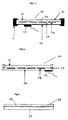
- a solar or photovoltaic cell module (hereafter referred to as a solar cell module) comprises a single solar cell or a planar assembly of interconnected solar cells supported by a load carrying supporting member. Solar cell modules are typically encapsulated to protect the cell from the environment.
- the supporting member of the solar cell module may be a top layer or superstrate which is transparent to sunlight i.e. positioned between the solar cells and a light source.
- the supporting member may be a back layer or substrate which is positioned behind the solar cells.
- solar cell modules comprise both a superstrate and a substrate.
- a series of solar cell modules are interconnected to form a solar array which functions as a single electricity producing unit wherein the cells and modules are interconnected in such a way as to generate a suitable voltage in order to power a piece of equipment or supply a battery for storage etc.
- solar cell modules are made by electrically interconnecting individual solar cells on a superstrate or substrate and laminating the interconnected cells into an integral solar cell module.
- the light-impinging surfaces of the cells are also generally protected from the environment (e.g. wind, rain, snow, dust and the like, by being covered with one or more encapsulant or barrier coating materials (Hereafter referred to as "encapsulant(s)").
- wafer based solar cell modules are designed using a superstrate which is transparent to sunlight fabricated from a material, usually in combination with a substrate and having one or more layers of encapsulant as a cell adhesive for adhering the cells to the superstrate and when present to the substrate.
- the superstrate typically a rigid panel, serves to protect one side of the solar cell from potentially harmful environmental conditions and the other side is protected by the combination of several layers of encapsulants and a substrate.
- solar cell module encapsulants A wide variety of materials have been proposed for use as solar cell module encapsulants. Common examples include films of ethylene-vinyl acetate copolymer (EVA), Tedlar ® from E.I. Dupont de Nemours & Co of Wilmington Delaware and UV curable urethanes.
- EVA ethylene-vinyl acetate copolymer
- Tedlar ® from E.I. Dupont de Nemours & Co of Wilmington Delaware
- UV curable urethanes The encapsulants are generally supplied in the form of films and are laminated to the cells, and superstrate and/or substrate.
- Prior art examples include the lamination of solar cells using adhesives as exemplified in US4331494 and the application of an acrylic polymer and a weather resistant layer as described in US4374955 .
- Solar cell modules have also been prepared by casting and curing acrylic prepolymers onto the solar cells as described in US4549033 , and also in European
- EP 0406814 and US 6320116 both describe encapsulation systems for solar cell or photovoltaic systems.
- Kondo et al. (Solar Energy Materials and Solar Cells 49 (1997) pages 127 to 133 ) describe the use of a thermosetting organic liquid resin as a means of encapsulating amorphous silicon photovoltaic modules but do not clearly identify the resin used.
- the encapsulants used are filmic and therefore the layers of encapsulant have to be laminated under heat and vacuum conditions which cause them to melt, bond to adjacent surfaces, and literally "encapsulate" the solar cells.
- a module may comprising a superstrate supporting a plurality of solar cells with a first layer of encapsulant which is transparent to sunlight, utilised as an adhesive, to adhere the superstrate to a series of interconnected solar cells.
- a second or rear layer of encapsulant may then be applied onto the first layer of encapsulant and interconnected solar cells.
- the second layer of encapsulant may be an additional layer of the same material as used for the first encapsulant, e.g. ethyl vinyl acetate (EVA) and/or may be transparent or any suitable colour.
- EVA ethyl vinyl acetate
- the substrate is present in the form of a rigid or, a stiff backskin to provide protection to the rear surface of the module.
- materials have been proposed for the substrate, which does not necessarily need to be transparent to light, these include the same materials as the superstrate e.g.
- ⁇ glass but may also include materials such as organic fluoropolymers such as ethylene tetrafluoroethylene (ETFE), Tedlar ® , or poly ethylene terephthalate (PET) alone or coated with silicon and oxygen based materials (SiO x ).
- organic fluoropolymers such as ethylene tetrafluoroethylene (ETFE), Tedlar ® , or poly ethylene terephthalate (PET) alone or coated with silicon and oxygen based materials (SiO x ).
- a protective seal is provided to cover the edges of the module, and a perimeter frame made of aluminium or a plastic material is provided to cover the seal.
- the frame protects the edges of the module when the front cover is made of a fragile material such as glass.
- the module is mounted in the frame.
- Frames suitable for use in combination with solar cell modules comprise mounting holes which are provided to enable easy mounting of the resulting framed module to a suitable object in the field.
- the mounting process will be accomplished using any appropriate mounting systems e.g. by way of screws, bolts, nuts and the like.
- polymeric frames made from moulded thermoplastic materials such as polyurethane are commonly used. These may be prepared by reaction injection moulding polyurethane to form a frame around an amorphous silicon cell module. Reaction injection moulding may be done in situ (i.e., on the module), this generally leads to a significant cost saving.
- this moulding process shows several disadvantages. For example, this process includes the use of a chemical precursor (e.g., isocyanate) which poses environmental hazards. This process also requires a mould, further adding to the overall manufacturing cost.
- the modules made by this process tend to be smaller because of the higher cost of the mould and the limited strength of the resulting polymeric frame.
- the encapsulant is still based on several layers of laminated thermoplastics such as EVA and a fluoropolymer such as ETFE copolymer.
- EVA laminated thermoplastics
- ETFE copolymer a fluoropolymer
- the only cost saving is derived from the cost reduction of the frame but potentially renders the resulting solar cell module more brittle.
- thermoplastic laminates are well known to have poor adhesive properties relative to glass. This problem whilst not always initially evident often leads to gradual delamination of a thermoplastic layer from glass surfaces in a solar cell over periods of prolonged weathering. The delamination process results in several negative effects on cell efficiency; such as it causes water accumulation in the encapsulant ultimately resulting in cell corrosion. These laminates also have a low UV resistance and as such discolour, generally turning yellow or brown over the lifetime of a solar cell, leading to a non-aesthetically pleasing module.
- a substantial amount of adhesive may often be required to reduce delamination effects and UV screens need to be incorporated in the module to decrease long-term discolouration.
- the substrate material is generally expensive.
- EVA laminate EVA laminate
- Tedlar® a polyvinyl fluoride
- the other widely used substrate material is glass in glass/cell /glass configuration.
- the cost of the encapsulant and the substrate materials when required, represent a substantial fraction of the overall cost of each cell and/or module.
- the inventors have identified that the overall cost per solar cell module may be reduced by the use of one or more liquid silicone encapsulants enabling the utilisation of a continuous encapsulation process which thereby eliminates several stages in the current solar cell module manufacturing process.
- the fact that the laminate encapsulants are replaced by a liquid encapsulant which hardens under infrared radiation or thermal cure reduces or eliminates the handling of laminate sheets and avoids the need for laminators, that increase both encapsulation batch time and cost.
- the present invention furthermore avoids the problems caused by the production of waste from lamination processes, and the resulting associated materials cost.
- a solar cell module comprising:
- the solar cells have all their exposed surfaces disposed on either said superstrate or substrate.
- the solar cell may be a wafer or made from any suitable semi-conductor material such as crystalline or polycrystalline silicon or thin film silicon, e.g. amorphous, semi crystalline silicon, gallium arsenide, copper indium diselenide, cadmium telluride, copper indium gallium diselenide, mixtures including any one or more of the latter and the like.
- crystalline or polycrystalline silicon or thin film silicon e.g. amorphous, semi crystalline silicon, gallium arsenide, copper indium diselenide, cadmium telluride, copper indium gallium diselenide, mixtures including any one or more of the latter and the like.
- the wafer is polycrystalline or crystalline silicon.
- the solar cell may be any suitable type solar cell including simple wafer but also split-spectrum cells and the like.
- the module may be any suitable type of solar cell module including concentrators etc.
- the rigid or flexible superstrate and/or substrate comprise a rigid superstrate which is transparent to light.
- the liquid silicone encapsulant in accordance with the invention preferably comprises:
- the proportions of components (A), (B), (C) and (D) may comprise any suitable amounts.
- the final viscosity of the resulting uncured composition may be, but is not essentially, able to self-level within a short period of time after having been dispensed.
- the preferred viscosity of the final composition is preferably from 100 to 10 000 mPa.s measured at 25°C, more preferably from 100 to 5000 mPa.s
- Component (A) is preferably a liquid diorganopolysiloxane, represented by the following average unit formula: R a SiO (4-a)/2 Wherein each R is the same or different and is a monovalent hydrocarbon group, for example a linear or branched alkyl group such as methyl, ethyl, propyl, isopropyl t-butyl, and pentyl; an alkenyl group such as vinyl, allyl, or hexenyl; and an aryl group such as phenyl. "a” is a number with an average value between 1.8 and 2.3.
- component (A) has a viscosity at 25°C of from 100 to 10,000 mPa.s, a molecular structure which is substantially linear although may be partially branched and a relatively low molecular weight of from 10000 to 50000, more preferably from 15000 to 30000.
- component (A) comprises alkenyl terminal groups.
- component (A) examples include
- Component (B) is a Silicone resin containing at least two alkenyl groups comprising SiO 4/2 units (also known as Q units) and units selected from R'SiO 3/2 (also known as T units), R' 2 SiO 2/2 , and R' 3 SiO 1/2 units, where each R' may be the same or different and is R or a hydrogen atom. It is preferred to disperse component (B) in a suitable amount of component (A) or a solvent to ensure ease of mixing with bulk of component (A).
- Any suitable solvents may be used such as for example aromatic solvents such as toluene and xylene, ketones such as methyl isobutyl ketone, alcohols such as isopropanol and non-aromatic cyclic solvents such as hexane.
- aromatic solvents such as toluene and xylene
- ketones such as methyl isobutyl ketone
- alcohols such as isopropanol
- non-aromatic cyclic solvents such as hexane.
- xylene is preferred.
- Component (C) is a cross-linking agent in the form of a polyorganosiloxane having at least two silicon-bonded hydrogen atoms per molecule and has the following average unit formula: R i b SiO (4-b)/2 where each R i may be the same or different and is hydrogen, an alkyl group such as methyl, ethyl, propyl, and isopropyl or an aryl group such as phenyl and tolyl.
- Component (C) may have a linear, partially branched linear, cyclic, or a net-like structure.
- organopolysiloxane examples include one or more of the following:
- the viscosity of the cross-linking agent (C) at 25°C is in a range of from 2 to 100,000 mPa.s. It is recommended that component (C) be added in an amount such that the mole ratio of silicon-bonded hydrogen atoms in the cross-linking agent (C) to the mole number of alkenyl groups in component (A) is in the range of from 0.1:1 to 5:1, more preferably it is in the range of from 0.8: 1 to 4:1. If the above ratio is lower than 0.1:1, the density of cross-linking will be too low and it will be difficult to obtain a rubber-like elastomer. A ratio having an excess of Si-H groups (i.e.> 1:1) is preferred to enhance adhesion between the superstrate/substrate e.g. glass and the encapsulant.
- Component (D) is a hydrosilylation (addition cure) catalyst may comprise any suitable platinum, rhodium, iridium, palladium or ruthenium based catalyst. However preferably component (D) is a platinum based catalyst.
- the platinum-based catalyst may be any suitable platinum catalyst such as for example a fine platinum powder, platinum black, chloroplatinic acid, an alcoholic solution of chloroplatinic acid, an olefin complex of chloroplatinic acid, a complex of chloroplatinic acid and alkenylsiloxane, or a thermoplastic resin that contain the aforementioned platinum catalyst.
- the platinum catalyst is used in an amount such that the content of metallic platinum atoms constitutes from 0.1 to 500 parts by weight per 1,000,000 parts by weight of component (A).
- the composition may also comprise one or more curing inhibitors in order to improve handling conditions and storage properties of the composition, for example acetylene-type compounds, such as 2-methyl-3-butyn-2-ol, 2-phenyl-3-butyn-2-ol, 3,5-dimethyl-1-hexyn-3-ol, 1-ethynyl-1-cyclohexanol, 1,5-hexadiene, 1,6-heptadiene; 3,5-dimethyl-1-hexen-1-yne; 3-ethyl-3-buten-1-yne and/or 3-phenyl-3-buten-1-yne; an alkenylsiloxane oligomer such as 1,3-divinyltetramethyldisiloxane, 1,3,5,7-tetravinyltetramethyl cyclotetrasiloxane, or 1,3-divinyl-1,3-diphenyldimethyldisiloxane; a silicon compound containing an
- the aforementioned curing inhibitors are used in an amount of from 0 to 3 parts by weight, normally from 0.001 to 3 parts by weight, and preferably from 0.01 to 1 part by weight per 100 parts by weight of component (A).
- Most preferable among the curing inhibitors are the aforementioned acetylene-type compounds, which demonstrate the best balance between storage characteristics and speed of curing when they are used in a combination with aforementioned component (D).
- adhesion promoters may also be used to enhance the adhesion of the encapsulant to a superstrate and/or substrate surface. Any suitable adhesion promoter may be utilised. Examples include
- Anti-soiling additives may be utilised, where required to prevent soiling when the solar cells are in use, particularly preferred are fluoroalkene or a fluorosilicone additives that has a viscosity of 10000 mPa.s such as:
- the anti-soiling additive is present in an amount of from 0 to 5 parts by weight, more preferably 0 to 2 parts by weight and most preferably 0 to 1.5 parts by weight.
- the anti-soiling additive is included in the encapsulant composition as well as when used in combination with the adhesive layer.
- a fire retardant Any suitable fire retardant or mixture of fire retardants may be used providing they do not negatively affecting the other physical properties of the encapsulant composition.
- alumina powder, or wollastonite as described in WO 00/46817 .
- the latter may be used alone or in combination with other fire retardants or a pigment such as titanium dioxide.
- the encapsulant need not be transparent to light, it may comprise a pigment.
- component (B) may be premixed with component (A) and component (C) and then co-cross-linked in the presence of a low level of platinum catalyst to form a tough polymer network.
- a small amount of a catalyst inhibitor such as ethylhexynol may be added to prolong the bath time of the encapsulant.
- the mixture When heated above 90 °C, the mixture initially forms a non-transparent two-phase system due to the presence of the anti-soiling additive and then becomes highly transparent.
- adhesion promoter is preferably use. It is believed that the adhesion promoter migrates to the interface of the topcoat and reacts irreversibly with adjacent surfaces. This strong adhesion allows the module to function in wide range of temperatures from ambient temperature to extremes without delaminating.
- the combination of encapsulant and topcoat is designed to replace multiple layers and material chemistry of the classical configuration (EVA and fluoropolymer laminate) by two layers based on one core chemistry.
- the topcoat preferably covers the entire cell interconnects; it functions as an outer layer i.e. as an environmentally protecting layer.
- Component (B) of the composition as hereinbefore described is provided because silicone resins of this type impart outstanding UV resistance to the encapsulant and therefore there is no need for the inclusion of one or more UV screen additives which in the case of most prior art formulations was typically essential.
- the cured liquid silicone encapsulant of the type described in the present invention exhibits long term UV & visual light transmission thereby allowing the maximum amount of light to reach solar cells.
- an adhesive layer comprising a further liquid silicone encapsulant may be utilised for the adhesion of the wafer type solar cells onto the load bearing support, typically a superstrate.
- the liquid silicone encapsulant utilised as the intermediate adhesive layer (henceforth referred to as the adhesive) is preferably substantially the same basic formulation as the single layer encapsulant described to above and preferably comprises:
- the proportions of components (Ai), (Bi), (Ci) and (Di) may comprise any suitable amounts.
- the final viscosity of the resulting uncured composition may be, but is not essentially, able to self-level within a short period of time after having been dispensed.
- the preferred viscosity of the final composition is preferably from 100 to 2000 mPa.s measured at 25°C, more preferably from 500 to 1000 mPa.s.
- the viscosity of component (Ai) of the adhesive is lower than the viscosity of component (A) of the aforementioned encapsulant.
- the encapsulant comprises a resin fraction of between 20% to 90% by weight, preferably between 25% to 70% and more preferably between 30 - 60% and the adhesive comprises a resin fraction of from 20- 30 % by weight.
- the adhesive may also comprise any one or more of the optional additives described with respect to the encapsulant formulation.
- the adhesive layer comprises a suitable adhesion promoter, most preferably one of the adhesion promoters listed above with respect to the encapsulant composition.
- the adhesive composition may be cured by any suitable process, for example component (Bi) may be premixed with components (Ai) and (Ci) and then co-cross-linked in the presence of platinum catalyst to form a tough network.
- a catalyst inhibitor such as for example ethylhexynol
- a small amount of adhesion promoter typically an alkoxysilane, is added and the ratio of Si-H bonds to Si-alkenyl bonds is lower than 1:1, such as for example 0.6: 1.
- adhesion promoter migrates to the interface of the encapsulant and reacts irreversibly with adjacent surfaces. This strong adhesion allows the module to function over a wide range of temperatures without or substantially without delaminating.
- the excess of alkenyl groups also helps the bonding/adhesion of the intermediate layer of adhesive with the encapsulant which is in this case functioning as a topcoat.
- Both the encapsulant and, the adhesive provide homogeneous and transparent silicone films that maintains a high flexibility due to the presence of the linear or substantially linear polymers of component (A).
- the encapsulant when cured, has a higher tear resistance than the adhesive.
- the anti-soiling additives are added to the encapsulant, to increase the soil resistance of the material and are used in amounts which will not noticeably negatively affect the abrasion resistance properties thereof.
- the anti-soiling additives are believed to migrate and spread rapidly at the silicone/air interface making a low surface energy surface but remain chemically bonded to the silicone matrix.
- the soil accumulation on the outwardly facing side (at the interface with the environment) of the encapsulant is inversely proportional to the surface energy, which is related to the level of anti-soiling additives on the surface.
- anti-soiling additives In use when anti-soiling additives are included in the encapsulant composition; first, a surface phase separation occurs; the anti-soiling additive migrates to the surface and then reacts with the cross-linker giving a fluorine-covered surface.
- the platinum concentration at the surface increases due to inhibitor evaporation, leading to a gradient cure rate of the film from the surface to the bulk. The overall result providing a much harder surface and smoother bulk material that allows stress relaxation interface between the glass and the wafer.
- the invention features a transparent encapsulant formed of a silicone composition that provides good adhesive properties to the front glass and to the solar cells.
- the encapsulant plays the role of a potting material, showing a good adhesion to the interconnected solar cells, to the connecting wires and to the superstrate e.g. a glass plate (wafer modules).
- the adhesion of the encapsulant to solar cells requires a good wetting of the cell and on an occasion, it was found desirable to provide such wetting by means of the adhesive, which preferably has a lower viscosity than the encapsulant.
- peroxide cure encapsulant product any suitable liquid silicone composition may be used.
- peroxide catalysts are used for free-radical based reactions between siloxanes comprising:
- any suitable liquid silicone polymer may be utilised together where appropriate with a UV photoinitiator.
- any or all of the additives described above (with the exception of the cure inhibitors which are specific to hydrosilylation type catalysis) may be utilised
- Any other suitable cure system for curing organopolysiloxanes may be utilised providing the uncured organopolysiloxane composition used is suitable for application in accordance with any one of the processes described below.
- the inventors have also found a new way of passivating the surface of a solar cell and/or photovoltaic cell which may be encapsulated by any system i.e. using the composition as described in the present invention or the prior art processes and lamination techniques.
- the coating of the cell surface with a trialkoxysilane results in a primer or passivating layer which has good adhesion to the cell surface and typically to the encapsulant used. It will passivate the surface and thereby increase the wetting of the cell(s) in order to reduce or avoid problems with bubble formation between the cell and the encapsulant and/or adhesive. It will also protect the cell after encapsulation from water ingress and corrosion.
- the chosen silane may be applied as a precoating onto the solar cell(s) or may be added in a suitable concentration in the encapsulant composition.
- the precoating may comprise the silane alone or a solution of the silane in a solvent such as an alcohol, the latter of which is allowed to evaporate after application.
- the layer of the passivation coating might be as small as 2 ⁇ m thick. Most preferably the passivation layer is provided on wafer type solar cells.
- the silane has the formula: (R 1 O) 3 Si R 2 wherein R' is an alkyl group comprising 1 to 6 carbon atoms, R 2 is selected from the group of an alkoxy group comprising 1 to 6 carbon atoms, an alkyl group comprising 1 to 6 carbon atoms an alkenyl group comprising 1 to 6 carbon atoms, an acrylic group or an alkyl acrylic group.
- the trialkoxysilane is for example, a trimethoxysilane or triethoxysilane, most preferably methacrylopropyltrimethoxysilane.
- the current standard industry process generally utilizes an EVA (ethyl vinyl acetate) thermoplastic encapsulant and a laminatable backing material such polyester/Tedlar ® and the cell or array of cells/module is prepared using a lamination technique.
- EVA ethyl vinyl acetate
- a laminatable backing material such polyester/Tedlar ®
- the cell or array of cells/module is prepared using a lamination technique.
- a suitable laminator is used to laminate the following "sandwich" of layers.
- the standard process uses the laminator apparatus to melt the layers of the "sandwich” at a temperature in the region of 140°C (actual temperature used is determined in view of the actual composition being laminated) under vacuum for about 20 minutes per module.
- the next step of the batch process is usually the application a protective seal is provided to cover the edges of the module, followed by the framing of the module in the perimeter frame, typically made of aluminium or a plastic material and discussed previously.
- the overall operation is carried out in a batch mode and is typically slow and very labour intensive.
- the inventors have found that no additional adhesive is required as the encapsulant bonds sufficiently well directly with the solar cell and substrate/superstrate.
- an adhesive layer is required to adhere the solar cell, (i.e. the wafer) to the superstrate or substrate. Whilst this may be in the form of a layer of the encapsulant as described above, the adhesive described above is preferably used.
- the liquid encapsulant and the adhesive are both designed to cure and therefore harden in a well-defined thickness when submitted to infrared or thermal radiation.
- the use of encapsulant, and where required the adhesive enables the user to operate a continuous process in which a liquid silicone encapsulant may be applied onto solar cells by way of any suitable type of dispensing equipment such as for example curtain coaters, spray devices die coaters, dip coaters, extrusion coaters, knife coaters and screen coaters and the like.
- the pre and post encapsulated modules may be fed continuously using a conveyor for planar and rigid superstrates or substrates such as glass or fed in a roll to roll process for flexible superstrates or substrates such as stainless steel foils.
- One major advantage of the process in accordance with the present invention is that the encapsulant is therefore applied to the cell surface without or substantially without air bubble entrapment, a major problem under current processes because air bubbles are believed to retain moisture in high humidity conditions and in use solar cells can be subjected to huge temperature variations.
- the presence of moisture is detrimental to solar cell modules as it condenses into liquid water which may induce local corrosion of metallic contacts, on solder or on solar cells and furthermore may cause early delamination of the modules.
- the adhesive as hereinbefore described is preferably sprayed, coated or dispensed uniformly onto the back of a superstrate or substrate, e.g. a glass plate by means of curtain coaters, spray devices, die coaters, dip coaters, extrusion coaters, knife coaters and screen coaters and the like, preferably a curtain coater. Then the interconnected solar cells are deposited onto/in to the uncured adhesive.
- the adhesive is then cured/hardened thermally or by infrared radiation in such a way that the adhesive fixes the interconnected solar cells in a predefined position on the superstrate/substrate, by a suitable heating or IR radiation source for example a continuous oven or an in-place heating means such as an oven or hot plate or the like.
- a suitable heating or IR radiation source for example a continuous oven or an in-place heating means such as an oven or hot plate or the like.
- an amount of encapsulant as described hereinbefore is uniformly applied to totally encapsulate the whole module by means of curtain coaters, spray devices, die coaters, dip coaters, extrusion coaters, knife coaters and screen coaters and the like, preferably a curtain coater and the resulting module is then cured/hardened thermally or by infrared radiation using a suitable heating or IR radiation source for example a continuous oven or an in-place heating, preferably a continuous oven.
- a suitable heating or IR radiation source for example a continuous oven or an in-place heating, preferably a continuous oven.
- encapsulant or if used adhesive is sprayed, coated or dispensed uniformly onto a glass superstrate/substrate and then the interconnecting solar cells are carefully immersed into a further amount of the same material and subsequently the resulting module is cured and hardened either thermally or by infrared radiation and where required a top-coat of encapsulant is sprayed, coated or dispensed (as described above) uniformly onto the cured adhesive and subsequently is cured and hardened either thermally or by infrared radiation as described above.
- the frame or edge sealing material may be applied to the substrate/superstrate before encapsulation and not after completion of the encapsulation process via the laminating processes of the prior art. This forms a guide for where the encapsulant and/or adhesive needs to be applied in liquid form.
- both encapsulant and adhesive may be carried out at about room temperature but some heating may be utilised up to e.g. a temperature of 75°C, preferably no greater than 50°C in order to reduce the viscosity of the encapsulant or adhesive being applied on to the module.
- the electrical leads in a module are treated using either of the above suggested methods are protected against coating with encapsulant and/or if used adhesive.
- the protected leads may be further bonded into an electrical junction box on the substrate or back skin material to form an integral seal.
- the liquid silicone coatings may be sealed and inserted into a metal, thermoplastic or elastomeric frame which also provide additional protection against water ingress at the edge of the panel.
- a silicone encapsulant in accordance with the present invention such a frame was not necessarily required unlike for solar cell modules prepared by the prior art lamination type processes.
- a continuous process using one or more means of coating the encapsulant and adhesive (where used) such as curtain coaters, spray devices and die coaters dip coaters, extrusion coaters, knife coaters and screen coaters and the like, although curtain coaters are preferred followed by an appropriate curing step, typically using a thermal or IR oven.
- curtain coaters such as curtain coaters, spray devices and die coaters dip coaters, extrusion coaters, knife coaters and screen coaters and the like, although curtain coaters are preferred followed by an appropriate curing step, typically using a thermal or IR oven.
- the viscosity of the coatings involved are suitable for use in combination with the means of applying the coating such as a curtain coater, although the process is preferably used in combination with encapsulant and adhesive formulation of the type described herein.
- the viscosity of the uncured composition is no greater than 50000 mPa.s and most preferably no greater than 40000mPa.s.
- curtain coating is a process for applying a thin layer of liquid onto a solid material.
- Curtain coating machines are adapted to disperse liquid at a controlled rate over the width of its coating head onto a target (in the case of this application solar cell modules).
- the resulting wide, thin flow of liquid resembles a "curtain” hence the name "Curtain Coater.”
- the ability of the user to control both the flow rate of the liquid and the speed of the target through the curtain of liquid a very accurate thickness of the coat is obtained.
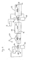
- Encapsulant or adhesive is initially retained in a reservoir tank, and when required is pumped from the tank, through a filter to coating head.
- the coating head may be either pressurised or non-pressurised depending on the viscosity of the coating being used (but in the present invention will usually be pressurized due to the viscosity of the encapsulant and adhesive when used.
- the encapsulant or adhesive flows through a dye in the coating head to form a 'curtain' of liquid under the effects of gravity.
- the Solar cell module to be coated is transferred along an in-feed conveyor, through the curtain of material, and onto an out-feed conveyor.
- the 'curtain' of encapsulant or adhesive is wider than the solar cell modules being coated so that all excess material falls through a gap between the in-feed and out-feed conveyors into a collection trough, and flows back to the feed tank, thereby avoiding any unnecessary waste.
- the feed tank is typically deep and constructed with baffles, so that the encapsulant or adhesive must follow a "tortuous" path, thus allowing time for any entrained air to escape before getting to the pump suction.
- a curtain coater is generally used for processes involving much less viscous liquids and it was imperative for the process of the present invention that the curtain coater used did not cause frothing and or bubbling.
- Several adjustments were required in the stock equipment to handle liquids of the viscosities of the encapsulant and adhesive described in the present invention. These were mainly directed to reducing the amount entrained air in the system to minimise the likelihood of the encapsulant and adhesive where used to foam or retain air bubbles.
- the curtain coater was preferably fitted with high powered pumps as the standard diaphragm pumps cannot be used since they introduce air into the system and would not be practical for application of the liquid encapsulant which may have a relatively high viscosity for a liquid of up to e.g. 10.000 mPa.s.
- the curtain coater has a centre feed system. This is because whilst lower viscosity liquid can be fed from any position on the coater head, but as the viscosity of the liquids utilised is higher than normally expected for use with this type of coater resulting in the need for longer times than normal being required for levelling the encapsulant and/or adhesive in the modules.
- the curtain coater feeder head utilises surface feed to avoid the entrainment of air. This is because whilst lower viscosity liquids of the type typically applied by curtain coaters are fed in any submerged depth position (z dimension) from the bottom to the top of the coater head tank, normally it is fed in a submerged manner to control splashing.
- the curtain coater has an anti-splash "pan" at the bottom of the curtain fall.
- This is provided in the form of a rolled metal pan which is provided to contribute to the laminar flow into the discharge and help prevent entrained air.
- Feed tanks are preferably both larger (overall capacity) and taller than normal feed tanks used for standard curtain coaters, to allow entrained air bubbles to rise to the surface of the tank according to Stokes law, and again help reduce the entrained air.
- the normal operating speed of the curtain coater may be lowered as compared to prior art curtain coaters. This is preferable because the lower operating speed range of the coater conveying system in order to allow better speed control of the speed of feeding the glass superstrates and/or substrates through the curtain coater, thereby providing better control curtain thickness.
- the curtain coater comprises a plurality of several curtain guides to the coater head to control the width of the curtain and/or allow the use of a multiple series of curtains.
- This provided coating flexibility and permitted the use of the same coating equipment for the coating of many different sizes of solar modules and arrays and the like.
- the curtain coater comprises a long return pipe and coalescer to remove gross bubbles from the system.
- the curtain coater may also optionally comprise a heating system to heat the liquid as it approaches the curtain. Heating the encapsulant and adhesive when used to about 50° C, has the advantage of reducing the viscosity and enhances the probability of any microscopic bubbles present in the composition to be applied to rise to the surface.
- the encapsulant and adhesive is de-aired prior to coating.
- Any suitable de-airing process may be utilised, e.g. by vacuum but preferably the curtain coater is provided with a semi-continuous vacuum stripper to de-air liquid before feeding it into or back into the coater head.
- a multi-axis robot (preferably six axes) may be integrated into the system for automating the accurate positioning of the solar cell modules on the in-feed conveyor belt and for accurately inserting/placing a solar cell or series of interconnected solar cells in position on the substrate or superstrate.
- This is particularly preferred in the case of wafer based solar cell systems where positioning of the cell on the superstrate or substrate is particularly critical.
- Any suitable robot may be utilised.
- the robotic gripper for holding and manipulating the solar cells or solar cell modules i.e. the device attached to the mounting arm of the robot that will manipulate the solar cells or solar cell modules
- the gripper plate preferably has at least one vacuum cup per cell to avoid any stress on the tabs over, under, and between the cells.
- a single vacuum cup is utilised pulling the cell upward to four Teflon pins that determined an exact position.
- Teflon pins that determined an exact position.
- one or two small vacuum cups are utilized, pulling the solar cell upward to a positioning stops or pins that determine the exact position of the cell relative to the substrate or superstrate and enable exact placement of the cell on the substrate or superstrate.
- the robot may for example pick up these a solar cell or series of interconnected solar cells from a fixed position and then place them into a thin liquid silicone layer on a superstrate or substrate (a glass plate).
- the glass plate may be edged with a cured sealant dam to hold the liquid in place.
- the glass plate may be mounted on top of a special near-IR oven that was fabricated to cure the liquid as the cells were held in place by the robot.
- the robot was adapted to manipulate the cells so that the best wetting method could be determined. In general, in the case of a single solar cell one edge of the solar cell was placed into the liquid and the remainder of the solar cell was lowered at a predetermined speed and angle to allow a meniscus of liquid to gradually flow over and wet the cell.
- the robot comprises a servomotor such that the speed of insertion of the solar cell is gradually decreased as the angle of the cell into the liquid became closer to the horizontal.
- the cells were applied without bubble formation.
- any suitable oven may be utilised for curing applied layers of encapsulant and adhesive, continuous ovens are particularly preferred for curing applied layers of encapsulant.
- the continuous ovens may comprise short wave IR emitters (wavelength 1.2 to 1.4 ⁇ m), medium wave IR emitters (wavelength 1.4 to 2.7 ⁇ m) but preferably comprise medium wave emitters and the temperature in the oven will be optimised for the coating concerned but will typically be in the region of from about 120 to about 200°C.
- the module containing a solar cell or series of interconnected solar cells is held in place by means of the robot and cured in situ using any appropriate heating means such as a static oven or hot plate at a temperature of in the region of between 150 and 250°C.
- a process for the application of both adhesive and encapsulant may for example comprise the following steps:
- the resulting post-cured panel "assembly" is then conveyed through a second curtain coater where a layer of from 20 ⁇ m to 1200 ⁇ m, preferably between 50 ⁇ m to 1000 ⁇ m, more preferably between 200 ⁇ m to 700 ⁇ m even more preferably 400 ⁇ m to 800 ⁇ m and most preferably 400 ⁇ m to 700 ⁇ m of the encapsulant is applied in a very even coat.
- the module having had the encapsulant applied is then conveyed through a suitable continuous (e.g. convective/IR) oven where the encapsulant cures into a smooth tough backing material.
- a suitable continuous e.g. convective/IR
- the final framed panel is then conveyed into a staging area which is similar and may even be the same as for existing systems where the electrical junction box is attached, and the panel is either packaged or progresses, where required, to a framing step.
- the framing material used is a thermoplastic or other suitable damping material also helps in this step because the cured framing material is bolted into an aluminium profile without any "squeeze out". This squeeze out of excess frame protection material is a problem with the double sided tape or sealant that is currently used in the industry, since it requires trimming and glass cleaning.
- the entire process in accordance with the present invention is an automated assembly line, or continuous unit-operation manufacturing, using electronic process control such as PLC.
- electronic process control such as PLC.
- sensors for any mismatches in rates of particular unit-operations.
- the continuous process of the present invention provides one linear meter of panel per minute which is a significant improvement over the current production speed.
- FIGS. 1 and 2 illustrate conventional wafer type solar cell modules.
- a wafer type solar cell module 1 with a Tedlar ® substrate or backskin 2.
- the module also consists of a front glass superstrate 3, interconnected solar cells 4 sandwiched between two EVA sheets 5,6.
- a further interconnecting layer 9 comprising any suitable material may be provided between EVA sheets 5,6, however, typically interconnecting layer 9 comprises a mixture of materials from the two EVA sheets 5,6.
- Tedlar ® substrate or backskin 2 is prelaminated to EVA sheet 6 before lamination in the solar cell module.
- the module 1 is edged with rubber seal 7 that makes a junction to an aluminium frame 8.
- FIG.2 there is shown a conventional thin film type solar cell module10 with a TEFZEL superstrate 11, a thin film silicon solar cell 12 on stainless steel substrate 13, sandwiched between two EVA sheets 14, 15.
- a further interconnecting layer 16, comprising a suitable material may be provided between EVA sheets 14 and 15, however, typically interconnecting layer 16 comprises a mixture of materials from the two EVA sheets 14,15.
- the encapsulation is obtained by means of lamination techniques such that the different layers shown are laminated with their neighbours. This process can be labourious and must be carried out in a batch type process.
- FIG. 3 illustrates a wafer type solar module 20 with a perimeter aluminium frame 21, a front glass superstrate 22, a junction box 23 and interconnected solar cells 24 encapsulated in accordance with a cured silicone encapsulant 25 in accordance with the present invention.
- a substrate 26 is shown but whilst this may be utilised typically the encapsulant of the present invention to encapsulate a solar cell module should suffice without the need for any such backskin unless there is a specific reason due to the application involved.
- FIG.4 illustrates a wafer module 30 without a classical perimeter aluminium frame of the type indicated as 21 in FIG.3 . It comprises a front glass superstrate 31 and a junction box 32. Interconnected wafer type solar cells 34 are provided in predetermined positions relative to each other 34 and the superstrate 31 in a layer of silicone adhesive 33. A top-coat of silicone encapsulant 35 is provided as a hard surface to protect the wafers 34 from the environment in order to enhance the lifetime of the solar module as a means of generating electricity from sunlight. Electrical leads linking adjacent wafers 34 are coated in such a way that they may be further bonded into the back skin material or as in this case the silicone encapsulant to form an integral seal.
- FIG. 5 is provided to illustrate an encapsulated thin film type solar module in accordance with the present invention.
- a substrate or support 37 onto which has been coated a thin film of suitable semi-conducting material 39.
- the thin film is encapsulated using a layer of the silicone encapsulant 38 in accordance with the present invention.
- the thin film will have been applied previously onto substrate 37 by, for example, chemical vapour deposition or sputtering techniques.
- FIG. 6 is intended to assist the reader to appreciate the continuous encapsulation process described in the present invention.
- the process described relates to the encapsulation of a wafer type solar cell modules requiring both an adhesive layer and an encapsulant layer to fully encapsulate the module.
- a collector 55 is positioned under curtain coater 54 to collect unused silicone adhesive.
- a pump (not shown) is provided to return said unused silicone adhesive from collector 55 to a storage tank 56 which supplies silicone adhesive to curtain coater 54.
- a six-axis robot 57 is utilised for the accurate placement of solar cells or groups of interconnected solar cells into or onto a layer of uncured silicone adhesive on module 53b before curing of the silicone adhesive. Any suitable number of electrically interconnected solar cells may be utilised.
- a first oven 58 is provided as the means of curing the adhesive layer.
- a second curtain coater 59 is provided for the application of silicone encapsulant onto the cured adhesive layer of module 53d.
- a collector 60 is provided to collect unused silicone encapsulant which is returned to a storage tank 61 or direct to curtain coater 59 for reuse.
- a second oven 62 is provided to cure the encapsulant layer onto the adhesive layer.
- a Solar cell module is initially placed on conveyor belt 50 and is transported to the end of conveyor 50 and through a curtain of liquid silicone adhesive supplied by curtain coater 54, as indicated by module 53a. Subsequent to application of the liquid silicone adhesive the module is transported along conveyor 51 to a predetermined position (as identified by module 53b) where a solar cell or series of interconnected solar cells are accurately positioned at a predetermined position in or on the uncured liquid adhesive layer by robot 57. Subsequent to the positioning of the cell(s), the module continues to be transported along conveyor 51 through a continuous oven 58 (it will be appreciated that the continuous oven is only one of the alternative means of curing the adhesive layer). Preferably when used the oven is of an IR type.
- a module is transported to the end of conveyor 51 to the second curtain coater 59 where a layer of liquid silicone encapsulant is applied (53d).
- the module is then transported through oven 62 on conveyor 52 in order to cure the encapsulant layer on top of the adhesive layer (53e), after which the fully encapsulated solar cell may be removed from the conveyor and stored for future use.
- Table 1 ComDarative Ultraviolet and Visible light transmission as a function of wavelength for EVA (ELVAX) and silicone material prepared in example 1.
- Example 2 Silicone composition that exhibit higher Taber abrasion resistance than the ETFE /EVA laminates.
- Film samples of similar composition as the one described in example 1 were submitted to a Taber abrasion tester (Taber 5131 equipped with calibrase CS-10 abrading wheels) while measuring the light transmission change as function of number of cycles.
- Figure 1 indicates that after 40 and 80 cycles, Tefzel ® has lost 25% and 35% of the light transmission respectively while the silicone encapsulate of this invention has lost only 8% of the light transmission after 100 cycles.
- Table 2 % of light Transmission loss as a function of abrasion cycles (Taber 5131, Calibrase CS-10) (1): Tefzel ® 25um (2) and (3) silicone encapsulant of this invention having 100 ⁇ m and 200um thickness.
- a laminate of EVA/TEFZEL ® having 200 ⁇ m thickness did not show higher abrasion resistance than sample 1.
- Number of Cycles Tefzel ® Thickness 25 ⁇ m Silicone Encapsulant
- Thickness 100 ⁇ m Silicone encapsulant
- Thickness 200 ⁇ m 0 100 100 100 5 80.6 98.3 98.3 20 96.5 96.5 40 76.2 - - 60 74.2 92.5 94.2 80 70.4 100 91.1 93.6
- Example 3 Shore A Hardness of cured silicone compositions in accordance with the invention showing a gradient toughness from the surface to the bulk.
- FIG. 1 Samples of similar composition as the one described in example 1 were cured in an aluminium cup to make 3 mm thick flat samples.
- the catalyst concentration was varied from 3.6 ppm to 7.1 ppm and the samples allowed to cure for 30 minutes at 120°C
- Figure 2 shows the variation of hardness in shore A for both top surface and the bottom surface of the sample as a function of catalyst concentration.
- the sample is skinned at the surface but do not fully cure.
- the example shows that the top surface is harder than the bottom surface indicating a faster or complete cure at the surface than in the bulk.
- the comparatively high hardness values indicate a high abrasion resistance and good surface properties, while low hardness value (bottom surface) indicates softer material, good for cell protection.
- Hard material which is in contact with a solar cell surface is likely to induce high stress at the cell/material surface and therefore a potential premature delamination, especially during thermal cycle change.
- Example 4 Adhesion of the encapsulant in accordance with the invention onto a glass panel after Damp heat test
- Samples of silicone encapsulant of similar composition as the one described in example 1 were coated onto a 20mm x 20mm glass panel to make a 1000 ⁇ m thick layer.
- a 15 mm x 15 mm silicon wafer of 650 ⁇ m thickness was immersed into the liquid encapsulant and then the assembly cured for 30 minutes at 120°C.
- the cured sample was submitted to a humidity/temperature aging test (80°C/85% Relative Humidity (RH)) for 41 days. No visible delamination could be observed, even after 60 days, the sample was still exhibiting a very good adhesion to the glass.
- RH Relative Humidity
- Example 5 Coating glass panels with a modified curtain coater of this invention and silicone solar encapsulant of this invention.
- 40 kg of the silicone encapsulant of this invention having a viscosity of 7000 mPa.s was fed into a curtain coater having 9 kg of polymer hold up and then pumped at 5.5 kg/min to make a nice curtain.
- 500 x 500 mm glass panels were fed continuously into the coater at 45 m/min to form a polymer film of 70 ⁇ m, after 6 passes under the curtain, a nice polymer film of 433 ⁇ m thickness was formed.
- the glass was then fed at 1 m/min into a 1 metre long infrared oven equipped with four lamps of 1000 watts each. The sample hardens rapidly to impart a high scratch resistance surface to the glass surface.
- Example 6 Coating solar glass panels with a modified curtain coater of this invention and silicone solar encapsulant of this invention.
- Example 5 was repeated except that four interconnected solar cells were manually glued on to the glass panels using a silicone base adhesive layer of 100 ⁇ m.
- the solar glass with the interconnect on the top side was passed through the curtain at 20 m/min to make a top layer of 200 ⁇ m, repeating the coating step once resulted in a solar panel coated with 400 ⁇ m encapsulating the interconnect.
- the top layer is then hardened by passing it at 0.5 m/min in 0.8 m long Infrared tunnel equipped with 8 kW IR lamps from Heraeus.
- Example 7 Encapsulation of a first series of interconnected commercially available a-Si thin film cells with the silicone encapsulant of the Present invention.
- a glass substrate was initially cleaned using a suitable solvent, in this case acetone and then the glass plate/thin film was treated with methacrylopropyltrimethoxysilane and dried using compressed air.
- the encapsulant used comprised 45 weight% of ⁇ , ⁇ -dimethylvinylsiloxy terminated polydimethylsiloxane having a molecular weight of 62000 g/mole and vinyl content of 0.15%; 18.6 weight % of trimethoxy terminated co polymer of dimethyl siloxane-co-methylhydrogensiloxane containing 1.45% of hydrogen units; 30.3 weight % (solids) of p-xylene solution of dimethyl vinylated MQ resin (63% resin in Xylene) 5 weight % of adhesion promoter, 0.14 weight % of diallylmaleate cure inhibitor, 0.11 weight % of platinum catalyst and 0.38 weight % of dimethylhydrogen siloxy terminated trifluoropropyl silsesquioxane.
- the encapsulant was applied onto the module manually and after levelling, was cured in a standard oven at a temperature of 120°C for 20 mins.
- Example 8 Humidity Freeze testing of a different series of interconnected commercially available a-Si thin film cells.
- any visual defect and any decrease in maximum power should not be greater than 5% all of which the thin film modules of the present invention using the encapsulant alone (i.e. no adhesive layer required).
- Example 9 Encapsulation of p-Si wafer type 1 with adhesive and encapsulant.
- a glass substrate was initially cleaned using a suitable solvent, in this case acetone and then the glass plate/thin film was treated with methacrylopropyltrimethoxysilane and dried using compressed air.
- the adhesive used comprised 27.5 weight % of ⁇ , ⁇ -dimethylvinylsiloxy terminated polydimethylsiloxane having a viscosity of about 10 000 mPa.s, molecular weight of 62000 g/mole and vinyl content of 0.15%; 45.8 weight % of ⁇ , ⁇ -dimethylvinylsiloxy terminated polydimethylsiloxane having a viscosity of about 450 mPa.s, 3 weight % of trimethoxy terminated co polymer of dimethyl siloxane-co-methylhydrogensiloxane containing 1.45% of hydrogen units; 18.3 weight % (solids) of p-xylene solution of dimethyl vinylated MQ resin (63% resin in Xylene) 5 weight %
- the adhesive was cured in place using a hot plate by heating for 7 min at 120°C or in a continuous process after application by a curtain coater the adhesive was cured in the module in a Mid IR oven having a temperature profile of 120°C and a speed of 0.5m per minute for a length of 5 m.
- the encapsulant composition was the same as detailed in Example 7. Encapsulant was applied onto the cured adhesive either manually in the lab or by means of a curtain coater. The encapsulant was cured in place using a hot plate by heating for 7 min at 120°C or in a continuous process after application by a curtain coater the adhesive was cured in the module in a Mid IR oven having a temperature profile of 120°C and a speed of 0.5m per minute for a length of 5 m.
- Example 10 Encapsulation of second type commercially available p-Si wafer with adhesive and encapsulant.
- example 8 the only difference from example 8 was the change in the solar cells used.
- the adhesive and encapsulant compositions were as described in example 8.
- Example 11 Coating glass panels with a modified curtain coater of this invention and silicone solar encapsulant of this invention.
- 40 Kg of the silicone encapsulant of this invention having a viscosity of 7000 mPa.s was fed into a curtain coater and was then pumped at 5.5 Kg/min to make a suitable curtain.
- 500 x 500 mm glass panels were fed continuously into the coater at 45 m/min to form a polymer film of 70 ⁇ m, after 6 passes under the curtain, an encapsulant film of 433 ⁇ m thickness was formed.
- the glass was then fed at 1 m/min into 1 meter long infrared oven equipped with 4 lamps of 1000 watts each.
- the encapsulant cured rapidly to impart a high scratch resistance surface to the glass surface.
- Example 12 Coating solar glass panels with a modified curtain coater of this invention and silicone solar encapsulant of this invention.
- Example 11 was repeated except that 4 interconnected solar cells were manually glued on to the glass panels by applying a layer of the adhesive having a thickness of 100 ⁇ m.
- the solar glass with the interconnect on the top side was passed through the curtain at 20 m/min to make a top layer of 200 ⁇ m, repeating the coating step once resulted in a solar panel coated with 400 ⁇ m encapsulating the interconnect.
- the top layer was then cured by passing through a 0.8 m long Infrared tunnel equipped with 8 kW IR lamps from Heraeus it at a speed of 0.5 m/min.
- the modules made in accordance with the present invention comprised a float glass superstrate (size 200mm x 200mm x 3mm) and a solar cell (size 125mm x 125mm x 350 ⁇ m) made from polycrystalline silicon which had been coated in silicon nitride. All modules tested were framed, prior to the application of the adhesive layer, in the lab using aluminium L-shaped profile frames in combination a suitable curable sealant adapted to seal the edges of the module and the frame.
- Each framed module in accordance with the present invention was encapsulated by first applying a layer of the silicone adhesive on to the glass plate.
- the solar cell i.e. a silicon wafer
- the adhesive layer, containing/comprising the cell was then cured using a hot plate.
- a layer of encapsulant was then applied on to the cured adhesive layer and subsequently cured in an oven.
- Encapsulated modules in accordance with the present invention were made using the adhesive having a formulation as described in Example 9 above and the encapsulant having a formulation as described in example 7 above.
- the standard comparative solar cells were standard modules made with EVA/TEDLAR laminate technology supported by tempered glass superstrates.
- the laminated modules were also framed as above using identical frames and sealant.
- the UV conditioning test followed the Irradiation test A-5, p13" procedures set down in Japanese International standard Test "JIS C 8917 Environmental and endurance test method for crystalline solar PV modules with reference to "JIS B 7753 Light-exposure and light-and-water-exposure apparatus" describing the UV ageing conditions.
- a Xenon Lamp (Wavelength range: 340nm) provided a continuous UV radiation at the surface of the sample: of 244.63 W/m 2 in 50% Relative Humidity for 600 hours.
- the resulting aged modules were subsequently conditioned for 2h at room temperature prior to testing.
- the sequence of test performed followed JIS C 8917.
- Tables 8 and 9 show the relative changes (delta results) comparing the initial and post ageing electrical performance of the standard modules (Table 8) and the modules in accordance with the present invention (Table 9).
- Table 8 Delta results for EVA / Tedlar based solar modules after UV ageing 600h EVA/Tedlar Isc (A) Voc (V) Isc (A) Vmax (V) Imax (A) FF (%) Pmax (W) Visuals Reference 0.7 -0.8 0.3 -1.0 0.5 -0.1 -0.5 Ok Comp A 1.1 -1.4 -0.3 -2.2 0.1 -0.3 -2.0 Ok Comp B 1.3 -0.9 0.7 -1.9 0.7 -1.0 -1.2 Ok Table 9 : Delta results for Modules encapsulated in accordance with the present invention after UV ageing 600h DC Encapsulant & adhesive Isc (A) Voc (V) Isc (A) Vmax (V) Imax (A) FF (%) Pmax (W) Visuals Ex Reference -
- Table 9 shows that all the samples in accordance with the present invention were encapsulated with no initial failure and passed the test. The loss in power is generally similar to the results for the Ex Ref sample. In general all the samples submitted to the 600h QUV ageing did not lose their property at all compared to the reference.
- Tables 10 and 11 provided the percentage changes in Pmax tested prior to and after ageing. Any loss in Pmax of more than 5 % is considered a failure.
- This test subjects samples to ageing conditions which enable the evaluation of the prospective ability of modules to withstand thermal expansion and contraction (through the thermal cycling) and to resist water penetration when submitted to extreme conditions of temperature and humidity (Humidity Freeze).
- Table 10 and 11 compare deltas results between the initial values and the final ones for the standard EVA/TEDLAR ® laminated solar modules (Table 10) and the solar modules encapsulated in accordance with the present invention.
- T able 10 EVA / Tedlar deltas results after 50 Thermal Cycles + 10 cycles Humidity Freeze conditions
- EVA/Tedlar Isc (A) Voc (V) Isc (A) Vmax (V) Imax (A) FF (%)
- Pmax (W) Reference 0.3 -0.9 -0.6 -2.1 -0.5 -1.2 -2.2 Comp C -0.5 0.4 -1.4 -0.4 -0.7 0.0 -1.1 Comp D -0.1 -0.6 -1.5 -1.4 -1.7 -1.1 -3.0 Comp E -0.7 -0.2 -1.5 -0.2 -0.1 1.5 -0.3
- Table 11 Encapsulant / adhesive in accordance with the present invention deltas results after 50 Thermal Cycles + 10 cycles Humidity Freeze conditions
- Example 13 Further samples as described in Example 13 were subjected to the sequence of test commonly referred to as Damp Heat Conditioning as defined in each of IEC 6-1215, IEEE 1262, UL1703.
- the results provided in Tables 12 and 13 are determined by the relative percentage change of initial and final electrical test results. Any loss in Pmax of more than 5 % was deemed a failure.
- Tables 12 and 13 contrast the results between the initial and the final electrical values ones for the two encapsulation technologies.
Landscapes
- Physics & Mathematics (AREA)
- Condensed Matter Physics & Semiconductors (AREA)
- Electromagnetism (AREA)
- General Physics & Mathematics (AREA)
- Engineering & Computer Science (AREA)
- Computer Hardware Design (AREA)
- Microelectronics & Electronic Packaging (AREA)
- Power Engineering (AREA)
- Photovoltaic Devices (AREA)
- Compositions Of Macromolecular Compounds (AREA)
- Sealing Material Composition (AREA)
- Adhesives Or Adhesive Processes (AREA)
Claims (29)
- Un module de cellules solaires comprenant :• un superstrat en verre (31),• une boîte de jonction (32),• des cellules solaires de type galettes interconnectées (34) situées dans des positions prédéterminées par rapport au superstrat (31) dans une couche d'adhésif en silicone (33),• un enduit extérieur d'agent d'encapsulation en silicone (35) prévu pour protéger les galettes (34) et des fils électriques reliant des galettes adjacentes enduits de telle sorte que lesdits fils puissent en outre être liés dans un matériau de peau de dos ou l'agent d'encapsulation en silicone pour former un scellement étanche d'une seule pièce.
- Un module de cellules solaires conformément à la revendication 1 dans lequel chaque cellule solaire est une galette, ladite cellule solaire étant réalisée à partir de silicium cristallin ou polycristallin ou de silicium en film mince, par ex. du silicium semi-cristallin amorphe, de l'arséniure de gallium, du diséléniure de cuivre et d'indium, du tellurure de cadmium, du diséléniure de gallium de cuivre et d'indium, des mélanges incluant un ou plusieurs éléments quelconques parmi ces derniers.
- Un module de cellules solaires conformément à la revendication 1 ou la revendication 2 dans lequel chaque cellule solaire est une galette réalisée à partir de silicium polycristallin ou monocristallin.
- Un module de cellules solaires conformément à une revendication précédente quelconque dans lequel la viscosité de la composition d'agent d'encapsulation en silicone liquide finale fait de préférence de 100 à 10 000 mPa.s mesurée à 25 °C.
- Un module de cellules solaires conformément à une revendication précédente quelconque dans lequel l'agent d'encapsulation en silicone liquide comprend• Composant (A) 100 parties en poids d'un diorganopolysiloxane liquide ayant au moins deux groupes Si-alcényles par molécule et une viscosité à 25 °C faisant de 100 à 15 000 mPa.s ;• Composant (B) 20 à 50 parties en poids d'une résine de silicone contenant au moins deux groupes alkényles ;• Composant (C) un agent de réticulation sous la forme d'un polyorganosiloxane ayant au moins deux atomes d'hydrogène liés par silicium par molécule, dans une quantité telle que le rapport entre le nombre de moles liées d'hydrogène par silicium et le nombre total de moles liées de groupes alkényles par silicium est de 0,1/1 à 5/1 ;• Composant (D) un catalyseur d'hydrosilation, la quantité de métal dans ledit catalyseur d'hydrosilation étant de 0,01 à 500 parties en poids pour 1 000 000 parties en poids de composant (A).
- Un module de cellules solaires conformément à la revendication 5 dans lequel le rapport entre le nombre de moles liées d'hydrogène par silicium et le nombre total de moles liées de groupes alkényles par silicium dans le composant (A) est > 1/1.
- Un module de cellules solaires conformément à la revendication 5 ou la revendication 6 dans lequel la composition comprend de plus un ou plusieurs promoteurs d'adhésion et / ou agents anti-salissure et / ou inhibiteurs de cuisson et / ou un silane de la formule :
(R1O)3Si R2
R1 étant un groupe alkyle comprenant 1 à 6 atomes de carbone, R2 étant sélectionné dans le groupe comprenant un groupe alkoxy comprenant 1 à 6 atomes de carbone, un groupe alkyle comprenant 1 à 6 atomes de carbone, un groupe alkényle comprenant 1 à 6 atomes de carbone, un groupe acrylique ou un groupe acrylique alkyle. - Un module de cellules solaires conformément à une revendication précédente quelconque dans lequel il est situé une couche adhésive comprenant un adhésif en silicone liquide conçu pour faire adhérer des cellules solaires sur un superstrat ou un substrat.
- Un module de cellules solaires conformément à quelle revendication précédente dans lequel la viscosité de la composition d'agent d'encapsulation en silicone liquide finale fait de préférence de 100 à 2 000 mPa.s mesurée à 25 °C.
- Un module de cellules solaires conformément à la revendication 8 ou la revendication 9 dans lequel l'adhésif en silicone liquide comprend :• Composant (Ai) 100 parties en poids d'un diorganopolysiloxane liquide ayant au moins deux groupes Si-alcényles par molécule et une viscosité à 25 °C faisant de 100 à 10 000 mPa.s ;• Composant (Bi) 20 à 40 parties en poids d'une résine de silicone contenant au moins deux groupes alkényles ;• Composant (Ci) un agent de réticulation sous la forme d'un polyorganosiloxane ayant au moins deux atomes d'hydrogène liés par silicium par molécule, dans une quantité telle que le rapport entre le nombre de moles liées d'hydrogène par silicium et le nombre total de moles liées de groupes alkényles par silicium est de 0,1/1 à 1/1 ;• Composant (Di) un catalyseur d'hydrosilation, la quantité de métal dans ledit catalyseur d'hydrosilation étant de 0,01 à 500 parties en poids pour 1 000 000 parties en poids de composant (Ai).
- Un module de cellules solaires conformément à la revendication 5 dans lequel le rapport entre le nombre de moles liées d'hydrogène par silicium et le nombre total de moles liées de groupes alkényles par silicium dans le composant (A) est < 1/1.
- Un module de cellules solaires conformément à la revendication 10 ou 11 dans lequel la composition adhésive comprend de plus un promoteur d'adhésion et / ou un inhibiteur de cuisson et / ou un silane de formule :
(R1O)3Si R2
R1 étant un groupe alkyle comprenant 1 à 6 atomes de carbone, R2 étant sélectionné dans le groupe parmi un groupe alkoxy comprenant 1 à 6 atomes de carbone, un groupe alkyle comprenant 1 à 6 atomes de carbone, un groupe alkényle comprenant 1 à 6 atomes de carbone, un groupe acrylique ou un groupe acrylique alkyle. - Un module de cellules solaires conformément à une revendication précédente quelconque comprenant un adhésif et un agent d'encapsulation, l'agent d'encapsulation comprenant une fraction résine comprise entre 20 % et 90 % en poids et l'adhésif ayant une fraction de résine allant de 20 à 30 % en poids.
- Un module de cellules solaires conformément à une revendication précédente quelconque dans lequel l'agent d'encapsulation cuit sans libérer de composants volatils.
- Un module de cellules solaires conformément à une revendication précédente quelconque dans lequel l'agent d'encapsulation et / ou l'adhésif en silicone cuit présente une transmission de lumière substantiellement équivalente à du verre.
- Un module de cellules solaires conformément à une revendication précédente quelconque dans lequel la cellule solaire ou la série de cellules solaires sont prétraitées préalablement à l'adhésion et / ou l'encapsulation avec un silane de la formule :
(R1O)3Si R2
R1 étant un groupe alkyle comprenant 1 à 6 atomes de carbone, R2 étant sélectionné dans le groupe parmi un groupe alkoxy comprenant 1 à 6 atomes de carbone, un groupe alkyle comprenant 1 à 6 atomes de carbone, un groupe alkényle comprenant 1 à 6 atomes de carbone, un groupe acrylique ou un groupe acrylique alkyle. - Un procédé d'encapsulation de module de cellules solaires en continu comprenant les étapes consistant à situer une boîte de jonction, appliquer un adhésif en silicone sur un superstrat en verre, déposer des cellules solaires interconnectées sur / dans l'adhésif non cuit, cuire l'adhésif thermiquement ou par rayonnement infrarouge d'une façon telle que l'adhésif fixe les cellules solaires interconnectées dans une position prédéfinie sur le superstrat, puis appliquer uniformément par vaporisation, enduction ou dispensation un volume prédéterminé d'un agent d'encapsulation en silicone liquide sur un module de cellules solaires et cuire ledit agent d'encapsulation thermiquement ou par rayonnement infrarouge.
- Un procédé d'encapsulation de module de cellules solaires en continu conformément à la revendication 17 avec un agent d'encapsulation conformément à une quelconque des revendications 4 à 7.
- Un procédé d'encapsulation de module de cellules solaires en continu conformément à la revendication 17 ou la revendication 18 dans lequel l'agent d'encapsulation en silicone liquide est appliqué en utilisant une encolleuse à rideau.
- Un procédé d'encapsulation de module de cellules solaires en continu conformément à une quelconque des revendications 17 à 19 dans lequel l'agent d'encapsulation en silicone liquide est cuit dans un four continu.
- Un procédé d'encapsulation de module de cellules solaires en continu conformément à une quelconque des revendications 17 à 20 dans lequel la couche résultante d'agent d'encapsulation est un enduit en film mince uniforme ayant une épaisseur dans la gamme allant de 20 µm à 1 200 µm.
- Un procédé d'encapsulation de module de cellules solaires en continu conformément à la revendication 17 dans lequel l'adhésif en silicone liquide a une composition conformément à une quelconque des revendications 10 à 12.
- Un procédé d'encapsulation de module de cellules solaires en continu conformément à une quelconque des revendications 17 à 21 dans lequel le moyen pour appliquer l'agent d'encapsulation est conçu de telle sorte que l'agent d'encapsulation soit appliqué en un film uniforme dépourvu de bulle ou substantiellement dépourvu de bulle sur le dessus d'une cellule solaire dans le module.
- Un procédé d'encapsulation de module de cellules solaires en continu conformément à une quelconque des revendications 17 à 23 dans lequel le dépôt d'une cellule solaire ou d'une série de cellules solaires dans un agent d'encapsulation en silicone liquide ou un adhésif en silicone liquide de première couche se fait par un préhenseur à ventouse contrôlé par un robot à six axes, ou un autre positionnement automatique, et un septième axe ou un autre préhenseur est utilisé pour contrôler le positionnement de l'ensemble de cellules solaires en une couche de liquide très mince de 100 à 700 µm.
- Un procédé d'encapsulation de module de cellules solaires en continu conformément à une quelconque des revendications 17 à 23 où un matériau thermoplastique ou thermo-élastomérique est appliqué pour former un cadre entourant un module cuit afin de protéger les bords du panneau d'une infiltration d'eau.
- Un module de cellules solaires d'un procédé d'encapsulation de module de cellules solaires en continu conformément à une quelconque des revendications 17 à 23 dans lequel un silane de la formule :
(R1O)3Si R2
R1 étant un groupe alkyle comprenant 1 à 6 atomes de carbone, R2 étant sélectionné dans le groupe parmi un groupe alkoxy comprenant 1 à 6 atomes de carbone, un groupe alkyle comprenant 1 à 6 atomes de carbone, un groupe alkényle comprenant 1 à 6 atomes de carbone, un groupe acrylique ou un groupe acrylique alkyle ; est utilisé pour pré-traiter une cellule solaire ou une série de cellules solaires préalablement à l'adhésion et / ou l'encapsulation. - Utilisation d'un agent d'encapsulation en silicone liquide pour encapsuler un module de cellules solaires conformément à la revendication 1.
- Utilisation conformément à la revendication 27 dans laquelle l'agent d'encapsulation est une composition conformément à une quelconque des revendications 4 à 8.
- Un module de cellules solaires pouvant être obtenu par le procédé conformément à une quelconque des revendications 16 à 25.
Applications Claiming Priority (3)
| Application Number | Priority Date | Filing Date | Title |
|---|---|---|---|
| GB0315846A GB0315846D0 (en) | 2003-07-07 | 2003-07-07 | Solar cells and encapsulation thereof |
| GB0412516A GB0412516D0 (en) | 2004-06-04 | 2004-06-04 | Encapsulation of solar cells |
| PCT/EP2004/007807 WO2005006451A1 (fr) | 2003-07-07 | 2004-07-02 | Encapsulation de piles solaires |
Publications (3)
| Publication Number | Publication Date |
|---|---|
| EP1644989A1 EP1644989A1 (fr) | 2006-04-12 |
| EP1644989B1 EP1644989B1 (fr) | 2011-10-19 |
| EP1644989B9 true EP1644989B9 (fr) | 2012-04-04 |
Family
ID=34066605
Family Applications (1)
| Application Number | Title | Priority Date | Filing Date |
|---|---|---|---|
| EP04741014A Revoked EP1644989B9 (fr) | 2003-07-07 | 2004-07-02 | Encapsulation de piles solaires |
Country Status (7)
| Country | Link |
|---|---|
| US (2) | US8847063B2 (fr) |
| EP (1) | EP1644989B9 (fr) |
| JP (3) | JP2007527109A (fr) |
| KR (2) | KR101157407B1 (fr) |
| AT (1) | ATE529896T1 (fr) |
| ES (1) | ES2375607T3 (fr) |
| WO (1) | WO2005006451A1 (fr) |
Cited By (2)
| Publication number | Priority date | Publication date | Assignee | Title |
|---|---|---|---|---|
| US10076896B2 (en) | 2015-06-25 | 2018-09-18 | Alta Devices, Inc. | Pressurized heated rolling press for manufacture and method of use |
| US11211517B2 (en) | 2015-06-25 | 2021-12-28 | Utica Leaseco, Llc | Pressurized heated rolling press for manufacture and method of use |
Families Citing this family (138)
| Publication number | Priority date | Publication date | Assignee | Title |
|---|---|---|---|---|
| ATE529896T1 (de) | 2003-07-07 | 2011-11-15 | Dow Corning | Einkapselung für solarzellen |
| JP4908736B2 (ja) * | 2003-10-01 | 2012-04-04 | 東レ・ダウコーニング株式会社 | 硬化性オルガノポリシロキサン組成物および半導体装置 |
| GB0502120D0 (en) * | 2005-02-02 | 2005-03-09 | Powertile Ltd | Solar tile assemblies |
| US20070056626A1 (en) * | 2005-09-12 | 2007-03-15 | Solaria Corporation | Method and system for assembling a solar cell using a plurality of photovoltaic regions |
| US8227688B1 (en) | 2005-10-17 | 2012-07-24 | Solaria Corporation | Method and resulting structure for assembling photovoltaic regions onto lead frame members for integration on concentrating elements for solar cells |
| US7910822B1 (en) | 2005-10-17 | 2011-03-22 | Solaria Corporation | Fabrication process for photovoltaic cell |
| KR20080072834A (ko) * | 2005-11-04 | 2008-08-07 | 다우 코닝 코포레이션 | 광전지의 캡슐화 |
| US20080047599A1 (en) * | 2006-03-18 | 2008-02-28 | Benyamin Buller | Monolithic integration of nonplanar solar cells |
| US7235736B1 (en) * | 2006-03-18 | 2007-06-26 | Solyndra, Inc. | Monolithic integration of cylindrical solar cells |
| US8183458B2 (en) * | 2007-03-13 | 2012-05-22 | Solyndra Llc | Photovoltaic apparatus having a filler layer and method for making the same |
| US8207442B2 (en) | 2006-04-18 | 2012-06-26 | Itn Energy Systems, Inc. | Reinforcing structures for thin-film photovoltaic device substrates, and associated methods |
| EP2041801A2 (fr) * | 2006-06-05 | 2009-04-01 | Dow Corning Corporation | Cellule solaire avec couche de résine de silicone |
| DE102006033296A1 (de) * | 2006-07-17 | 2008-01-31 | Manz Automation Ag | Anlage zur Strukturierung von Solarmodulen |
| US8124870B2 (en) | 2006-09-19 | 2012-02-28 | Itn Energy System, Inc. | Systems and processes for bifacial collection and tandem junctions using a thin-film photovoltaic device |
| EP2099985A1 (fr) * | 2006-12-27 | 2009-09-16 | Dow Corning Corporation | Fixation structurelle de modules solaires à des cadres par vitrage transparent |
| US7910392B2 (en) | 2007-04-02 | 2011-03-22 | Solaria Corporation | Method and system for assembling a solar cell package |
| US20090056806A1 (en) * | 2007-09-05 | 2009-03-05 | Solaria Corporation | Solar cell structure including a plurality of concentrator elements with a notch design and predetermined radii and method |
| EP1986351B1 (fr) | 2007-04-26 | 2010-02-24 | Alcatel Lucent | Réseau optique, unité de surveillance et procédé de surveillance |
| US8119902B2 (en) | 2007-05-21 | 2012-02-21 | Solaria Corporation | Concentrating module and method of manufacture for photovoltaic strips |
| EP2168167B1 (fr) * | 2007-06-19 | 2019-04-10 | QuNano AB | Structure de cellule solaire à nanofil |
| US20090029053A1 (en) * | 2007-07-25 | 2009-01-29 | United Solar Ovonic Llc | Method for stabilizing silicone material, stabilized silicone material, and devices incorporating that material |
| CN101363266A (zh) * | 2007-08-09 | 2009-02-11 | 鸿富锦精密工业(深圳)有限公司 | 太阳能屋 |
| JP5252472B2 (ja) * | 2007-09-28 | 2013-07-31 | シャープ株式会社 | 太陽電池、太陽電池の製造方法、太陽電池モジュールの製造方法および太陽電池モジュール |
| US7910035B2 (en) | 2007-12-12 | 2011-03-22 | Solaria Corporation | Method and system for manufacturing integrated molded concentrator photovoltaic device |
| TW200929578A (en) * | 2007-12-31 | 2009-07-01 | Ind Tech Res Inst | Transparent sola cell module |
| WO2009091068A1 (fr) * | 2008-01-15 | 2009-07-23 | Affinity Co., Ltd. | Module de cellule solaire et son procédé de fabrication |
| US8662008B2 (en) * | 2008-02-07 | 2014-03-04 | Sunpower Corporation | Edge coating apparatus for solar cell substrates |
| EP2093804A1 (fr) * | 2008-02-19 | 2009-08-26 | Helianthos B.V. | Système de cellules solaires avec encapsulant |
| US8420412B2 (en) | 2008-03-14 | 2013-04-16 | Dow Corning Corporation | Method of forming a photovoltaic cell module |
| US20110197947A1 (en) | 2008-03-20 | 2011-08-18 | Miasole | Wire network for interconnecting photovoltaic cells |
| US8912429B2 (en) * | 2008-03-20 | 2014-12-16 | Hanergy Holding Group Ltd. | Interconnect assembly |
| US20100043863A1 (en) | 2008-03-20 | 2010-02-25 | Miasole | Interconnect assembly |
| AU2009231138A1 (en) * | 2008-04-04 | 2009-10-08 | Bayer Materialscience Ag | Photovoltaic solar module |
| DE102008037821A1 (de) * | 2008-08-14 | 2010-02-25 | Fraunhofer-Gesellschaft zur Förderung der angewandten Forschung e.V. | Verfahren zur Herstellung von mechanisch vorgespannten Solarzellenverbunden sowie mechanisch vorgespanntes Solarzellenmodul |
| US20110197955A1 (en) * | 2008-09-30 | 2011-08-18 | Adco Products, Inc. | Solar module having an encapsulant mounting adhesive |
| KR20120130299A (ko) | 2008-10-31 | 2012-11-30 | 다우 코닝 코포레이션 | 광전지 모듈 및 이의 형성 방법 |
| US8048250B2 (en) * | 2009-01-16 | 2011-11-01 | Genie Lens Technologies, Llc | Method of manufacturing photovoltaic (PV) enhancement films |
| US8338693B2 (en) * | 2009-01-16 | 2012-12-25 | Genie Lens Technology, LLC | Solar arrays and other photovoltaic (PV) devices using PV enhancement films for trapping light |
| US7904871B2 (en) * | 2009-01-16 | 2011-03-08 | Genie Lens Technologies, Llc | Computer-implemented method of optimizing refraction and TIR structures to enhance path lengths in PV devices |
| US7968790B2 (en) * | 2009-01-16 | 2011-06-28 | Genie Lens Technologies, Llc | Photovoltaic (PV) enhancement films for enhancing optical path lengths and for trapping reflected light |
| US20100212734A1 (en) * | 2009-02-24 | 2010-08-26 | Xiaolin Sha | Encapsulation process for thin-film solar cells |
| KR100997738B1 (ko) * | 2009-03-23 | 2010-12-01 | 이광석 | 태양전지 모듈의 제조방법 및 그에 따라 제조된 태양전지 모듈 |
| US8222514B2 (en) * | 2009-04-28 | 2012-07-17 | 7Ac Technologies, Inc. | Backskin material for solar energy modules |
| US8633478B2 (en) * | 2009-06-19 | 2014-01-21 | Dow Corning Corporation | Use of ionomeric silicone thermoplastic elastomers in electronic devices |
| CN101931012B (zh) * | 2009-06-26 | 2012-12-12 | 比亚迪股份有限公司 | 一种太阳能电池背板及其制备方法以及使用该背板的太阳能电池组件 |
| FR2948499B1 (fr) * | 2009-07-24 | 2012-08-17 | Jerome Bouchet | Procede d'encapsulation de cellules photovoltaiques destinees a produire de l'electricite par exposition au soleil |
| US20110036400A1 (en) * | 2009-08-17 | 2011-02-17 | First Solar, Inc. | Barrier layer |
| US20110048505A1 (en) * | 2009-08-27 | 2011-03-03 | Gabriela Bunea | Module Level Solution to Solar Cell Polarization Using an Encapsulant with Opened UV Transmission Curve |
| JP5469966B2 (ja) * | 2009-09-08 | 2014-04-16 | 東京応化工業株式会社 | 塗布装置及び塗布方法 |
| JP5719546B2 (ja) * | 2009-09-08 | 2015-05-20 | 東京応化工業株式会社 | 塗布装置及び塗布方法 |
| KR101130197B1 (ko) * | 2009-09-28 | 2012-03-30 | 엘지전자 주식회사 | 태양전지 모듈 및 그 제조 방법 |
| KR101145927B1 (ko) | 2009-09-28 | 2012-05-15 | 엘지전자 주식회사 | 태양전지 모듈 및 그 제조 방법 |
| US8552288B2 (en) * | 2009-10-12 | 2013-10-08 | Sunpower Corporation | Photovoltaic module with adhesion promoter |
| US9029683B2 (en) * | 2009-10-16 | 2015-05-12 | Soleeva Solar, Inc. | Self-contained, multi-fluid energy conversion and management system for converting solar energy to electric and thermal energy |
| JP5545298B2 (ja) * | 2009-10-21 | 2014-07-09 | 信越化学工業株式会社 | 太陽電池モジュール表面保護用透明積層フィルム及び太陽電池モジュール |
| US20110124135A1 (en) * | 2009-11-24 | 2011-05-26 | International Business Machines Corporation | Solar Cell Module and Method for Assembling a Solar Cell Module |
| US20110129676A1 (en) * | 2009-12-01 | 2011-06-02 | Bravet David J | Multi-layered front sheet encapsulant for photovoltaic modules |
| DK2237325T3 (da) * | 2009-12-17 | 2011-08-01 | Kioto Photovoltaics Gmbh | Fotovoltaisk modul |
| WO2011084806A1 (fr) * | 2010-01-06 | 2011-07-14 | Dow Global Technologies Inc. | Dispositifs photovoltaïques résistant à l'humidité dotés d'une couche de protection de polysiloxane élastomère |
| JP2011171709A (ja) * | 2010-01-12 | 2011-09-01 | Rohm & Haas Co | 光起電モジュールの製造方法 |
| JP2011171710A (ja) | 2010-01-12 | 2011-09-01 | Rohm & Haas Co | 光起電モジュールの製造方法 |
| KR101031608B1 (ko) | 2010-01-29 | 2011-04-27 | 주식회사 인맥 | 태양광 모듈 생산 설비용 트리밍 장치 |
| WO2011107592A1 (fr) * | 2010-03-05 | 2011-09-09 | Momentive Performance Materials Gmbh | Composition durcissable de polyorganosiloxane destinée à une utilisation comme encapsulant pour un module de cellule solaire |
| US20110256657A1 (en) * | 2010-04-19 | 2011-10-20 | Du Pont Apollo Limited | Method of encapsulating photovoltaic panel |
| EP2388830A1 (fr) | 2010-05-20 | 2011-11-23 | Fundacion Inasmet | Modules photovoltaïques et son procédé de fabrication |
| US9061344B1 (en) | 2010-05-26 | 2015-06-23 | Apollo Precision (Fujian) Limited | Apparatuses and methods for fabricating wire current collectors and interconnects for solar cells |
| JP2011254009A (ja) * | 2010-06-03 | 2011-12-15 | Shin Etsu Chem Co Ltd | 太陽電池モジュール用シリコーン樹脂組成物及び太陽電池モジュール |
| CN102295911B (zh) * | 2010-06-24 | 2013-07-03 | 上海海鹰粘接科技有限公司 | 一种有机硅灌封胶及其制备方法和应用 |
| CN103026501B (zh) | 2010-06-30 | 2015-09-02 | 第一太阳能有限公司 | 用于光伏模块的防湿线路板 |
| WO2012044762A1 (fr) * | 2010-09-30 | 2012-04-05 | Dow Global Technologies Llc | Connecteur amélioré et assemblage de circuit électronique permettant d'améliorer la résistance d'isolement à l'eau |
| JP5681932B2 (ja) * | 2010-09-30 | 2015-03-11 | ユニヴァーシティ オブ サウス フロリダ | 封止を備えたオールスプレー式シースルー型有機ソーラアレイ |
| IT1402581B1 (it) * | 2010-09-30 | 2013-09-13 | Luxferov S R L | Pannello fotovoltaico ad alto rendimento ed elevata resistenza. |
| US10026859B2 (en) | 2010-10-04 | 2018-07-17 | Beijing Apollo Ding Rong Solar Technology Co., Ltd. | Small gauge wire solar cell interconnect |
| KR101337368B1 (ko) | 2010-10-27 | 2013-12-05 | 엘지디스플레이 주식회사 | 코팅장치 및 이를 이용한 코팅막 형성방법 |
| US9774198B2 (en) * | 2010-11-08 | 2017-09-26 | Brandon Culver | Wind and solar powered heat trace with homeostatic control |
| WO2012100788A1 (fr) * | 2011-01-26 | 2012-08-02 | Fraunhofer-Gesellschaft zur Förderung der angewandten Forschung e.V. | Récepteur concentrateur photovoltaïque et son utilisation |
| WO2012106433A2 (fr) | 2011-02-01 | 2012-08-09 | University Of South Florida | Photopile photovoltaïque organique à couche partiellement pulvérisée utilisant une monocouche auto-assemblée et procédé de fabrication |
| US9099605B2 (en) | 2011-02-14 | 2015-08-04 | University Of South Florida | Organic photovoltaic array and method of manufacture |
| WO2012112533A2 (fr) * | 2011-02-14 | 2012-08-23 | University Of South Florida | Générateur photovoltaïque organique et procédé de fabrication |
| CA2827659A1 (fr) | 2011-03-08 | 2012-09-13 | University Of South Florida | Micro-reseau solaire organique inverse pour applications dans des systemes micro-electromecaniques |
| US8951824B1 (en) | 2011-04-08 | 2015-02-10 | Apollo Precision (Fujian) Limited | Adhesives for attaching wire network to photovoltaic cells |
| USD699176S1 (en) | 2011-06-02 | 2014-02-11 | Solaria Corporation | Fastener for solar modules |
| US20130014808A1 (en) * | 2011-07-14 | 2013-01-17 | Sabic Innovative Plastics Ip B.V. | Photovoltaic modules and methods for making and using the same |
| GB201115223D0 (en) | 2011-09-02 | 2011-10-19 | Dow Corning | Method of fabricating solar modules |
| AT13179U1 (de) * | 2011-09-22 | 2013-08-15 | Inova Lisec Technologiezentrum | Photovoltaik-Modul |
| WO2013048758A2 (fr) * | 2011-09-29 | 2013-04-04 | Dow Global Technologies Llc | Interconnexion de cellule photovoltaïque |
| KR101305665B1 (ko) | 2011-10-17 | 2013-09-09 | 엘지이노텍 주식회사 | 태양광 발전장치 및 이의 제조방법 |
| DE102011085587A1 (de) * | 2011-11-02 | 2013-05-02 | Evonik Industries Ag | Glas - Photovoltaik - Pressure sensitive Adhesive-Verbund |
| US8853525B2 (en) | 2011-11-14 | 2014-10-07 | Prism Solar Technologies, Inc. | Frameless photovoltaic module |
| US10186624B2 (en) | 2011-11-14 | 2019-01-22 | Prism Solar Technologies, Inc. | Tiled frameless PV-module |
| TWM430703U (en) * | 2011-11-18 | 2012-06-01 | Hulk Energy Technology Co Ltd | Solar cell module |
| TW201347215A (zh) * | 2012-01-26 | 2013-11-16 | Dow Corning | 光伏打電池模組之形成方法 |
| TW201334959A (zh) * | 2012-01-26 | 2013-09-01 | Dow Corning | 光伏打電池模組及其形成方法 |
| WO2013112874A1 (fr) * | 2012-01-26 | 2013-08-01 | Dow Corning Corporation | Module de cellule photovoltaïque et son procédé de formation |
| DE102012101441A1 (de) * | 2012-02-23 | 2013-08-29 | Hanwha Q.CELLS GmbH | Solarmodul und Verfahren zu dessen Herstellung |
| DE202012101023U1 (de) | 2012-03-01 | 2013-06-04 | Solarworld Innovations Gmbh | Solarmodul |
| DE102012101710A1 (de) | 2012-03-01 | 2013-09-05 | Solarworld Innovations Gmbh | Verfahren zur Einkapselung einer Solarzelle in einer Polymermatrix |
| JP2015518274A (ja) | 2012-03-27 | 2015-06-25 | バイエル・インテレクチュアル・プロパティ・ゲゼルシャフト・ミット・ベシュレンクテル・ハフツングBayer Intellectual Property GmbH | ソーラーラミネートの製造のためのuv放射硬化性ポリウレタン樹脂の使用 |
| US9635783B2 (en) * | 2012-03-30 | 2017-04-25 | Sunpower Corporation | Electronic component housing with heat sink |
| JP5971178B2 (ja) * | 2012-04-23 | 2016-08-17 | 信越化学工業株式会社 | 太陽電池モジュール用シリコーン封止材及び太陽電池モジュール |
| JP5780209B2 (ja) | 2012-05-29 | 2015-09-16 | 信越化学工業株式会社 | 太陽電池モジュールの製造方法 |
| WO2014047006A1 (fr) * | 2012-09-18 | 2014-03-27 | Dow Corning Corporation | Procédé permettant de réduire et/ou de supprimer la dégradation induite par un potentiel des modules de cellules photovoltaïques |
| JP2014061561A (ja) * | 2012-09-20 | 2014-04-10 | Yaskawa Electric Corp | ロボットシステムおよび物品製造方法 |
| JP5862536B2 (ja) | 2012-10-04 | 2016-02-16 | 信越化学工業株式会社 | 太陽電池モジュールの製造方法 |
| JP5867356B2 (ja) | 2012-10-04 | 2016-02-24 | 信越化学工業株式会社 | 太陽電池モジュールの製造方法 |
| US9153729B2 (en) * | 2012-11-26 | 2015-10-06 | International Business Machines Corporation | Atomic layer deposition for photovoltaic devices |
| JP6387355B2 (ja) * | 2012-12-21 | 2018-09-05 | ダウ シリコーンズ コーポレーション | 層状ポリマー構造及び方法 |
| FR3001832B1 (fr) * | 2013-02-06 | 2015-02-20 | Arkema France | Utilisation d'une composition polymerique fluide pour l'encapsulation de modules photovoltaiques |
| US9112065B2 (en) * | 2013-03-14 | 2015-08-18 | Tsmc Solar Ltd. | Method of curing solar cells to reduce lamination induced efficiency loss |
| WO2014145609A1 (fr) | 2013-03-15 | 2014-09-18 | University Of South Florida | Procédé de masquage-empilement-décalage pour fabriquer un réseau solaire organique par pulvérisation |
| JP2015029077A (ja) | 2013-07-04 | 2015-02-12 | 信越化学工業株式会社 | 太陽電池モジュールの製造方法 |
| CN105592944B (zh) * | 2013-07-29 | 2018-05-11 | 贝克太阳能有限公司 | 对基板进行的空间有限的加工 |
| JP6233196B2 (ja) | 2013-08-30 | 2017-11-22 | 信越化学工業株式会社 | 太陽電池モジュールの製造方法 |
| JP5954281B2 (ja) | 2013-09-03 | 2016-07-20 | 信越化学工業株式会社 | 太陽電池封止用シリコーン接着剤シート並びにそれを用いた太陽電池モジュールの製造方法 |
| JP6217328B2 (ja) | 2013-11-11 | 2017-10-25 | 信越化学工業株式会社 | 太陽電池封止用紫外線遮蔽性シリコーン接着剤シート並びにそれを用いた太陽電池モジュール |
| JP2015201521A (ja) | 2014-04-07 | 2015-11-12 | 信越化学工業株式会社 | 太陽電池用シリコーン封止材料及び太陽電池モジュール |
| US10381499B1 (en) * | 2016-12-07 | 2019-08-13 | Solaero Technologies Corp. | Flexible solar array and method for fabricating the same |
| WO2016067516A1 (fr) * | 2014-10-27 | 2016-05-06 | パナソニックIpマネジメント株式会社 | Procédé de fabrication de module solaire et appareil de fabrication de module solaire |
| US10618264B2 (en) | 2014-11-26 | 2020-04-14 | The Boeing Company | Apparatuses and methods to prevent or minimize the effect of voids in bonded systems |
| US9590132B2 (en) | 2014-12-05 | 2017-03-07 | Solarcity Corporation | Systems and methods for cascading photovoltaic structures |
| US9991412B2 (en) * | 2014-12-05 | 2018-06-05 | Solarcity Corporation | Systems for precision application of conductive adhesive paste on photovoltaic structures |
| US9899546B2 (en) | 2014-12-05 | 2018-02-20 | Tesla, Inc. | Photovoltaic cells with electrodes adapted to house conductive paste |
| CN104409538A (zh) * | 2014-12-17 | 2015-03-11 | 苏州费米光电有限公司 | 一种便捷式太阳能板 |
| KR101640516B1 (ko) * | 2015-06-25 | 2016-07-19 | (주)크린플로 | 태양광 유리 패널 제조용 상·하판유리 접합 방법 및 이에 의해 제조된 태양광 유리 패널 |
| CN106558629A (zh) * | 2015-09-17 | 2017-04-05 | 中电电气(上海)太阳能科技有限公司 | 一种环保型太阳能电池组件及层压方法 |
| JP2017120873A (ja) | 2015-12-25 | 2017-07-06 | 京セラ株式会社 | 絶縁性ペーストおよびその製造方法並びに太陽電池素子の製造方法 |
| US10128391B2 (en) | 2016-06-22 | 2018-11-13 | Beijing Apollo Ding Rong Solar Technology Co., Ltd. | Photovoltaic module with flexible wire interconnection |
| CN106328741A (zh) * | 2016-08-29 | 2017-01-11 | 上海晶澳太阳能科技有限公司 | 一种高效高强度太阳能电池双玻组件 |
| US10584494B2 (en) | 2017-04-26 | 2020-03-10 | Owens Corning Intellectual Capital, Llc | Asphalt based roofing material with increased infrared reflectivity |
| US10490682B2 (en) | 2018-03-14 | 2019-11-26 | National Mechanical Group Corp. | Frame-less encapsulated photo-voltaic solar panel supporting solar cell modules encapsulated within multiple layers of optically-transparent epoxy-resin materials |
| CN108878564A (zh) * | 2018-07-04 | 2018-11-23 | 南通沃特光电科技有限公司 | 一种太阳能电池组件及其制备方法 |
| CN108767039B (zh) * | 2018-07-04 | 2020-10-30 | 绍兴越元科技有限公司 | 一种光伏电池板及其制备方法 |
| US20200009613A1 (en) * | 2018-07-09 | 2020-01-09 | Industrial Control Development, Inc. | Silicone coatings for exterior architectural substrates for buildings |
| US11271126B2 (en) | 2019-03-21 | 2022-03-08 | Beijing Apollo Ding Rong Solar Technology Co., Ltd. | Photovoltaic panels with folded panel edges and methods of forming the same |
| CN110600564A (zh) * | 2019-09-17 | 2019-12-20 | 湖南纵横空天能源科技有限公司 | 柔性砷化镓组件及制作工艺 |
| CN113540275A (zh) * | 2021-07-16 | 2021-10-22 | 彼博股份有限公司 | 一种曲面多形态集成光伏模块及其封装方法 |
| KR20240000830A (ko) * | 2022-06-24 | 2024-01-03 | 주식회사 메카로에너지 | 투광형 태양전지 및 그 제조 방법 |
| CN116864576B (zh) * | 2023-08-21 | 2024-03-01 | 盐城天合国能光伏科技有限公司 | 一种太阳能电池封装工艺 |
Family Cites Families (73)
| Publication number | Priority date | Publication date | Assignee | Title |
|---|---|---|---|---|
| US2613184A (en) * | 1951-11-08 | 1952-10-07 | Du Pont | Lubricating oil containing a copolymer of an ester of an unsaturated acid and a n-hydrocarbon amide of an unsaturated acid |
| US2938938A (en) * | 1956-07-03 | 1960-05-31 | Hoffman Electronics Corp | Photo-voltaic semiconductor apparatus or the like |
| US3083187A (en) * | 1959-06-22 | 1963-03-26 | California Research Corp | Detergent polyesters |
| US3284406A (en) * | 1963-12-18 | 1966-11-08 | Dow Corning | Organosiloxane encapsulating resins |
| US3565719A (en) * | 1967-05-17 | 1971-02-23 | Nasa | Solar panel fabrication |
| US4021357A (en) * | 1972-03-10 | 1977-05-03 | Texaco Inc. | Multifunctional tetrapolymer lube oil additive |
| US4056405A (en) | 1976-05-10 | 1977-11-01 | Solarex Corporation | Panel for solar energy cells |
| US4036767A (en) * | 1976-06-14 | 1977-07-19 | Texaco Inc. | Polymethacrylate additives and lubricating compositions thereof |
| US4089705A (en) * | 1976-07-28 | 1978-05-16 | The United States Of America As Represented By The Administrator Of The National Aeronautics And Space Administration | Hexagon solar power panel |
| US4037010A (en) * | 1976-08-02 | 1977-07-19 | Hughes Aircraft Company | Organic composites with in-situ formed fibers and extensible matrix |
| US4057439A (en) * | 1976-08-25 | 1977-11-08 | Solarex Corporation | Solar panel |
| US4143949A (en) | 1976-10-28 | 1979-03-13 | Bausch & Lomb Incorporated | Process for putting a hydrophilic coating on a hydrophobic contact lens |
| GB1592581A (en) * | 1977-06-16 | 1981-07-08 | Bfg Glassgroup | Solar panel |
| FR2395609A1 (fr) * | 1977-06-24 | 1979-01-19 | Radiotechnique Compelec | Panneau generateur a cellules solaires noyees dans un stratifie et procede pour l'obtenir |
| JPS54131485U (fr) * | 1978-03-02 | 1979-09-12 | ||
| FR2426337A1 (fr) * | 1978-05-19 | 1979-12-14 | Comp Generale Electricite | Panneau de cellules solaires et son procede de fabrication |
| US4167644A (en) * | 1978-09-29 | 1979-09-11 | Exxon Research & Engineering Co. | Solar cell module |
| US4374955A (en) * | 1980-06-11 | 1983-02-22 | California Institute Of Technology | N-Butyl acrylate polymer composition for solar cell encapsulation and method |
| GB2084793B (en) | 1980-09-22 | 1985-01-09 | Exxon Research Engineering Co | Method of fabricating solar cell modules |
| US4490500A (en) * | 1981-02-26 | 1984-12-25 | General Electric Company | Completely solventless two component RTV silicone composition |
| FR2501213A1 (fr) | 1981-03-05 | 1982-09-10 | Altulor Sa | Prepolymere acrylique et son application a l'encapsulation de photopiles |
| US4415759A (en) * | 1981-10-13 | 1983-11-15 | Vought Corporation | Solar power satellite |
| US4402841A (en) * | 1982-02-16 | 1983-09-06 | The Standard Oil Company | Extended service 5W-40 motor oil |
| US4430519A (en) * | 1982-05-28 | 1984-02-07 | Amp Incorporated | Electron beam welded photovoltaic cell interconnections |
| JPS5961077A (ja) * | 1982-09-29 | 1984-04-07 | Nippon Denso Co Ltd | アモルフアスシリコン太陽電池 |
| US4461922A (en) * | 1983-02-14 | 1984-07-24 | Atlantic Richfield Company | Solar cell module |
| DE3317396A1 (de) * | 1983-05-13 | 1984-11-15 | Henkel KGaA, 4000 Düsseldorf | Verwendung von coloymeren aus estern und amiden der acryl- und/oder methacrylsaeure als stockpunkterniedriger fuer paraffinloesungen |
| JPS6032352A (ja) * | 1983-08-01 | 1985-02-19 | Matsushita Electric Ind Co Ltd | 太陽電池モジュ−ル |
| IT1181905B (it) * | 1984-06-15 | 1987-09-30 | Anic Spa | Additivo multifunzionale per oli lubrificanti e procedimento per la sua preparazione |
| JPS6160792A (ja) * | 1984-08-31 | 1986-03-28 | Nippon Kokan Kk <Nkk> | 鋼板用冷間圧延油 |
| US4606834A (en) * | 1985-09-10 | 1986-08-19 | Texaco Inc. | Lubricating oil containing VII pour depressant |
| DE3607444A1 (de) * | 1986-03-07 | 1987-09-10 | Roehm Gmbh | Additive fuer mineraloele mit stockpunktverbessernder wirkung |
| DE3631125A1 (de) * | 1986-09-12 | 1988-03-24 | Wacker Chemie Gmbh | Verfahren zur herstellung von organopolysiloxanelastomeren und neue organosiliciumverbindungen |
| US4868251A (en) * | 1986-12-24 | 1989-09-19 | Allergan, Inc. | Ultraviolet light absorbing silicone compositions |
| JPS63188975A (ja) * | 1987-02-02 | 1988-08-04 | Sumitomo Electric Ind Ltd | 太陽電池モジユ−ルの製造方法 |
| JP2732524B2 (ja) * | 1987-07-08 | 1998-03-30 | 株式会社日立製作所 | 光電変換デバイス |
| FR2622891B1 (fr) * | 1987-11-05 | 1990-02-02 | Elf Aquitaine | |
| US5024953A (en) * | 1988-03-22 | 1991-06-18 | Hitachi, Ltd. | Method for producing opto-electric transducing element |
| FR2640272B1 (fr) * | 1988-12-12 | 1992-07-24 | Elf Aquitaine | Composes polymeriques resultant de la condensation d'une alkylene polyamine sur un copolymere ayant des groupements carboxyliques vicinaux et leur utilisation comme additifs aux lubrifiants |
| US4953577A (en) | 1989-07-06 | 1990-09-04 | Solarex Corporation | Spray encapsulation of photovoltaic modules |
| US5011544A (en) * | 1989-09-08 | 1991-04-30 | Solarex Corporation | Solar panel with interconnects and masking structure, and method |
| US5013468A (en) * | 1989-10-10 | 1991-05-07 | Texaco Inc. | Dispersant/antioxidant VII lubricant additive |
| US4941985A (en) * | 1989-12-01 | 1990-07-17 | Texaco Inc. | Dispersant/antioxidant VII lubricant additive |
| US5290366A (en) * | 1990-03-08 | 1994-03-01 | Siemens Solar Gmh | Laminated solar module |
| JPH0726851Y2 (ja) * | 1990-10-09 | 1995-06-14 | シャープ株式会社 | 太陽電池 |
| JPH04197663A (ja) * | 1990-11-27 | 1992-07-17 | Internatl Business Mach Corp <Ibm> | 印刷装置 |
| DE69320725T2 (de) * | 1992-06-29 | 1999-04-01 | Canon Kk | Harzzusammensetzung zum Dichten und eine mit Dichtharzzusammensetzung bedeckte Halbleitervorrichtung |
| JP3268893B2 (ja) * | 1993-06-29 | 2002-03-25 | キヤノン株式会社 | 光起電力素子の製造方法 |
| JP3267452B2 (ja) * | 1993-08-31 | 2002-03-18 | キヤノン株式会社 | 光電変換装置及び太陽電池モジュール |
| US5445891A (en) * | 1993-11-17 | 1995-08-29 | Dow Corning Toray Siliconco., Ltd. | Curable organopolysiloxane composition containing novel adhesion promoter |
| US5476553A (en) * | 1994-02-18 | 1995-12-19 | Ase Americas, Inc. | Solar cell modules and method of making same |
| JP2756082B2 (ja) * | 1994-04-28 | 1998-05-25 | キヤノン株式会社 | 太陽電池モジュールの製造方法 |
| JP3618802B2 (ja) * | 1994-11-04 | 2005-02-09 | キヤノン株式会社 | 太陽電池モジュール |
| US5569689A (en) * | 1995-10-02 | 1996-10-29 | General Electric Company | Addition-curable silicone adhesive compositions |
| JP3825843B2 (ja) * | 1996-09-12 | 2006-09-27 | キヤノン株式会社 | 太陽電池モジュール |
| US6320116B1 (en) * | 1997-09-26 | 2001-11-20 | Evergreen Solar, Inc. | Methods for improving polymeric materials for use in solar cell applications |
| US6175075B1 (en) * | 1998-04-21 | 2001-01-16 | Canon Kabushiki Kaisha | Solar cell module excelling in reliability |
| US6239378B1 (en) | 1999-02-02 | 2001-05-29 | Dow Corning Corporation | Flame resistant silicone rubber wire and cable coating composition |
| EP1054456A3 (fr) | 1999-05-17 | 2007-01-03 | Dai Nippon Printing Co., Ltd. | Couche de protection pour un module de cellules solaires, sa méthode de fabrication et module de cellules solaires |
| AU764832B2 (en) * | 1999-05-31 | 2003-09-04 | Kaneka Corporation | Solar battery module |
| JP3595731B2 (ja) | 1999-06-21 | 2004-12-02 | 信越化学工業株式会社 | 半導体装置封止用付加硬化型シリコーン組成物及び半導体装置 |
| JP2000036611A (ja) * | 1999-07-19 | 2000-02-02 | Canon Inc | 太陽電池モジュ―ル |
| JP3705343B2 (ja) * | 2000-07-19 | 2005-10-12 | 信越化学工業株式会社 | 付加反応硬化型シリコーンゴム組成物及びその製造方法 |
| JP2003069068A (ja) * | 2001-08-29 | 2003-03-07 | Canon Inc | 太陽電池モジュール |
| JP2003086822A (ja) | 2001-09-10 | 2003-03-20 | Aisin Seiki Co Ltd | 太陽電池モジュール及びその製造方法 |
| DE10204893A1 (de) * | 2002-02-06 | 2003-08-14 | Ge Bayer Silicones Gmbh & Co | Selbsthaftende additionsvernetzende Silikonkautschukmischungen, ein Verfahren zu deren Herstellung, Verfahren zur Herstellung von Verbund-Formteilen und deren Verwendung |
| DE10226626A1 (de) * | 2002-06-14 | 2004-01-15 | Wacker-Chemie Gmbh | Selbsthaftende additionsvernetzende Siliconzusammensetzungen |
| ATE529896T1 (de) | 2003-07-07 | 2011-11-15 | Dow Corning | Einkapselung für solarzellen |
| DE102005014289A1 (de) * | 2005-03-24 | 2006-09-28 | Ge Bayer Silicones Gmbh & Co. Kg | Selbsthaftende additionsvernetzende Siliconkautschukmischungen, ein Verfahren zu deren Herstellung, Verfahren zur Herstellung von Verbund-Formteilen und deren Verwendung |
| DE102006022097A1 (de) * | 2006-05-11 | 2007-11-15 | Wacker Chemie Ag | Selbsthaftende additionsvernetzende Siliconzusammensetzungen |
| JP5000566B2 (ja) | 2008-03-27 | 2012-08-15 | 信越化学工業株式会社 | 硬化性シリコーンゴム組成物、およびそれを封止材料として用いた光半導体装置 |
| KR20120130299A (ko) | 2008-10-31 | 2012-11-30 | 다우 코닝 코포레이션 | 광전지 모듈 및 이의 형성 방법 |
| WO2011107592A1 (fr) | 2010-03-05 | 2011-09-09 | Momentive Performance Materials Gmbh | Composition durcissable de polyorganosiloxane destinée à une utilisation comme encapsulant pour un module de cellule solaire |
-
2004
- 2004-07-02 AT AT04741014T patent/ATE529896T1/de not_active IP Right Cessation
- 2004-07-02 JP JP2006518177A patent/JP2007527109A/ja active Pending
- 2004-07-02 KR KR1020067000411A patent/KR101157407B1/ko active IP Right Grant
- 2004-07-02 ES ES04741014T patent/ES2375607T3/es active Active
- 2004-07-02 EP EP04741014A patent/EP1644989B9/fr not_active Revoked
- 2004-07-02 US US10/563,677 patent/US8847063B2/en active Active
- 2004-07-02 WO PCT/EP2004/007807 patent/WO2005006451A1/fr active Application Filing
- 2004-07-02 KR KR1020127003252A patent/KR101410709B1/ko active IP Right Grant
-
2011
- 2011-12-30 US US13/341,120 patent/US8847064B2/en active Active
-
2012
- 2012-07-10 JP JP2012154527A patent/JP2012253361A/ja active Pending
-
2014
- 2014-01-30 JP JP2014015468A patent/JP2014131055A/ja active Pending
Cited By (2)
| Publication number | Priority date | Publication date | Assignee | Title |
|---|---|---|---|---|
| US10076896B2 (en) | 2015-06-25 | 2018-09-18 | Alta Devices, Inc. | Pressurized heated rolling press for manufacture and method of use |
| US11211517B2 (en) | 2015-06-25 | 2021-12-28 | Utica Leaseco, Llc | Pressurized heated rolling press for manufacture and method of use |
Also Published As
| Publication number | Publication date |
|---|---|
| KR101157407B1 (ko) | 2012-06-21 |
| US20060207646A1 (en) | 2006-09-21 |
| ES2375607T3 (es) | 2012-03-02 |
| KR20060035733A (ko) | 2006-04-26 |
| EP1644989A1 (fr) | 2006-04-12 |
| JP2007527109A (ja) | 2007-09-20 |
| JP2012253361A (ja) | 2012-12-20 |
| JP2014131055A (ja) | 2014-07-10 |
| KR20120038476A (ko) | 2012-04-23 |
| US8847063B2 (en) | 2014-09-30 |
| ATE529896T1 (de) | 2011-11-15 |
| EP1644989B1 (fr) | 2011-10-19 |
| US8847064B2 (en) | 2014-09-30 |
| WO2005006451A1 (fr) | 2005-01-20 |
| US20120186631A1 (en) | 2012-07-26 |
| KR101410709B1 (ko) | 2014-06-25 |
Similar Documents
| Publication | Publication Date | Title |
|---|---|---|
| EP1644989B9 (fr) | Encapsulation de piles solaires | |
| US9991406B2 (en) | Curable polyorganosiloxane composition for use as an encapsulant for a solar cell module | |
| KR101952970B1 (ko) | 태양 전지 모듈의 제조 방법 | |
| TWI513025B (zh) | 光伏打電池模組及形成方法 | |
| CN1816916B (zh) | 太阳能电池组件、其封装方法、和液体硅氧烷封装剂封装太阳能电池组件的用途 | |
| EP2530741B1 (fr) | Module photovoltaïque | |
| KR102000793B1 (ko) | 태양 전지 모듈의 제조 방법 | |
| EP2879808B1 (fr) | Procédé pour la fabrication d'une structure de silicone multicouche | |
| EP2530740B1 (fr) | Module photovoltaïque | |
| TW201605980A (zh) | 太陽能電池用聚矽氧封裝材料組成物及太陽能電池模組 | |
| EP2530732B1 (fr) | Plaque pour cellules photovoltaïques | |
| US9385253B2 (en) | Method of manufacturing solar cell module | |
| KR20120086997A (ko) | 광전지 모듈 |
Legal Events
| Date | Code | Title | Description |
|---|---|---|---|
| PUAI | Public reference made under article 153(3) epc to a published international application that has entered the european phase |
Free format text: ORIGINAL CODE: 0009012 |
|
| 17P | Request for examination filed |
Effective date: 20060201 |
|
| AK | Designated contracting states |
Kind code of ref document: A1 Designated state(s): AT BE BG CH CY CZ DE DK EE ES FI FR GB GR HU IE IT LI LU MC NL PL PT RO SE SI SK TR |
|
| DAX | Request for extension of the european patent (deleted) | ||
| RIN1 | Information on inventor provided before grant (corrected) |
Inventor name: HABIMANA, JEAN DE LA CROI Inventor name: JENKINS, STEPHEN Inventor name: TERREAU, CHRISTINE |
|
| 17Q | First examination report despatched |
Effective date: 20080610 |
|
| TPAC | Observations filed by third parties |
Free format text: ORIGINAL CODE: EPIDOSNTIPA |
|
| GRAP | Despatch of communication of intention to grant a patent |
Free format text: ORIGINAL CODE: EPIDOSNIGR1 |
|
| GRAS | Grant fee paid |
Free format text: ORIGINAL CODE: EPIDOSNIGR3 |
|
| GRAA | (expected) grant |
Free format text: ORIGINAL CODE: 0009210 |
|
| STAA | Information on the status of an ep patent application or granted ep patent |
Free format text: STATUS: THE PATENT HAS BEEN GRANTED |
|
| AK | Designated contracting states |
Kind code of ref document: B1 Designated state(s): AT BE BG CH CY CZ DE DK EE ES FI FR GB GR HU IE IT LI LU MC NL PL PT RO SE SI SK TR |
|
| REG | Reference to a national code |
Ref country code: GB Ref legal event code: FG4D |
|
| REG | Reference to a national code |
Ref country code: CH Ref legal event code: EP |
|
| REG | Reference to a national code |
Ref country code: IE Ref legal event code: FG4D |
|
| REG | Reference to a national code |
Ref country code: DE Ref legal event code: R096 Ref document number: 602004034918 Country of ref document: DE Effective date: 20111222 |
|
| REG | Reference to a national code |
Ref country code: NL Ref legal event code: VDEP Effective date: 20111019 |
|
| REG | Reference to a national code |
Ref country code: ES Ref legal event code: FG2A Ref document number: 2375607 Country of ref document: ES Kind code of ref document: T3 Effective date: 20120302 |
|
| REG | Reference to a national code |
Ref country code: AT Ref legal event code: MK05 Ref document number: 529896 Country of ref document: AT Kind code of ref document: T Effective date: 20111019 |
|
| PG25 | Lapsed in a contracting state [announced via postgrant information from national office to epo] |
Ref country code: BE Free format text: LAPSE BECAUSE OF FAILURE TO SUBMIT A TRANSLATION OF THE DESCRIPTION OR TO PAY THE FEE WITHIN THE PRESCRIBED TIME-LIMIT Effective date: 20111019 |
|
| PG25 | Lapsed in a contracting state [announced via postgrant information from national office to epo] |
Ref country code: NL Free format text: LAPSE BECAUSE OF FAILURE TO SUBMIT A TRANSLATION OF THE DESCRIPTION OR TO PAY THE FEE WITHIN THE PRESCRIBED TIME-LIMIT Effective date: 20111019 Ref country code: SE Free format text: LAPSE BECAUSE OF FAILURE TO SUBMIT A TRANSLATION OF THE DESCRIPTION OR TO PAY THE FEE WITHIN THE PRESCRIBED TIME-LIMIT Effective date: 20111019 Ref country code: PT Free format text: LAPSE BECAUSE OF FAILURE TO SUBMIT A TRANSLATION OF THE DESCRIPTION OR TO PAY THE FEE WITHIN THE PRESCRIBED TIME-LIMIT Effective date: 20120220 Ref country code: GR Free format text: LAPSE BECAUSE OF FAILURE TO SUBMIT A TRANSLATION OF THE DESCRIPTION OR TO PAY THE FEE WITHIN THE PRESCRIBED TIME-LIMIT Effective date: 20120120 Ref country code: SI Free format text: LAPSE BECAUSE OF FAILURE TO SUBMIT A TRANSLATION OF THE DESCRIPTION OR TO PAY THE FEE WITHIN THE PRESCRIBED TIME-LIMIT Effective date: 20111019 |
|
| PG25 | Lapsed in a contracting state [announced via postgrant information from national office to epo] |
Ref country code: CY Free format text: LAPSE BECAUSE OF FAILURE TO SUBMIT A TRANSLATION OF THE DESCRIPTION OR TO PAY THE FEE WITHIN THE PRESCRIBED TIME-LIMIT Effective date: 20111019 |
|
| PLBI | Opposition filed |
Free format text: ORIGINAL CODE: 0009260 |
|
| PG25 | Lapsed in a contracting state [announced via postgrant information from national office to epo] |
Ref country code: DK Free format text: LAPSE BECAUSE OF FAILURE TO SUBMIT A TRANSLATION OF THE DESCRIPTION OR TO PAY THE FEE WITHIN THE PRESCRIBED TIME-LIMIT Effective date: 20111019 Ref country code: SK Free format text: LAPSE BECAUSE OF FAILURE TO SUBMIT A TRANSLATION OF THE DESCRIPTION OR TO PAY THE FEE WITHIN THE PRESCRIBED TIME-LIMIT Effective date: 20111019 Ref country code: BG Free format text: LAPSE BECAUSE OF FAILURE TO SUBMIT A TRANSLATION OF THE DESCRIPTION OR TO PAY THE FEE WITHIN THE PRESCRIBED TIME-LIMIT Effective date: 20120119 Ref country code: EE Free format text: LAPSE BECAUSE OF FAILURE TO SUBMIT A TRANSLATION OF THE DESCRIPTION OR TO PAY THE FEE WITHIN THE PRESCRIBED TIME-LIMIT Effective date: 20111019 Ref country code: CZ Free format text: LAPSE BECAUSE OF FAILURE TO SUBMIT A TRANSLATION OF THE DESCRIPTION OR TO PAY THE FEE WITHIN THE PRESCRIBED TIME-LIMIT Effective date: 20111019 |
|
| 26 | Opposition filed |
Opponent name: MOMENTIVE PERFORMANCE MATERIALS INC. Effective date: 20120717 |
|
| PLAX | Notice of opposition and request to file observation + time limit sent |
Free format text: ORIGINAL CODE: EPIDOSNOBS2 |
|
| PG25 | Lapsed in a contracting state [announced via postgrant information from national office to epo] |
Ref country code: RO Free format text: LAPSE BECAUSE OF FAILURE TO SUBMIT A TRANSLATION OF THE DESCRIPTION OR TO PAY THE FEE WITHIN THE PRESCRIBED TIME-LIMIT Effective date: 20111019 Ref country code: PL Free format text: LAPSE BECAUSE OF FAILURE TO SUBMIT A TRANSLATION OF THE DESCRIPTION OR TO PAY THE FEE WITHIN THE PRESCRIBED TIME-LIMIT Effective date: 20111019 |
|
| REG | Reference to a national code |
Ref country code: DE Ref legal event code: R026 Ref document number: 602004034918 Country of ref document: DE Effective date: 20120717 |
|
| PLAF | Information modified related to communication of a notice of opposition and request to file observations + time limit |
Free format text: ORIGINAL CODE: EPIDOSCOBS2 |
|
| PG25 | Lapsed in a contracting state [announced via postgrant information from national office to epo] |
Ref country code: AT Free format text: LAPSE BECAUSE OF FAILURE TO SUBMIT A TRANSLATION OF THE DESCRIPTION OR TO PAY THE FEE WITHIN THE PRESCRIBED TIME-LIMIT Effective date: 20111019 |
|
| PG25 | Lapsed in a contracting state [announced via postgrant information from national office to epo] |
Ref country code: MC Free format text: LAPSE BECAUSE OF NON-PAYMENT OF DUE FEES Effective date: 20120731 |
|
| REG | Reference to a national code |
Ref country code: CH Ref legal event code: PL |
|
| PLBB | Reply of patent proprietor to notice(s) of opposition received |
Free format text: ORIGINAL CODE: EPIDOSNOBS3 |
|
| PG25 | Lapsed in a contracting state [announced via postgrant information from national office to epo] |
Ref country code: LI Free format text: LAPSE BECAUSE OF NON-PAYMENT OF DUE FEES Effective date: 20120731 Ref country code: CH Free format text: LAPSE BECAUSE OF NON-PAYMENT OF DUE FEES Effective date: 20120731 |
|
| REG | Reference to a national code |
Ref country code: IE Ref legal event code: MM4A |
|
| PG25 | Lapsed in a contracting state [announced via postgrant information from national office to epo] |
Ref country code: FI Free format text: LAPSE BECAUSE OF FAILURE TO SUBMIT A TRANSLATION OF THE DESCRIPTION OR TO PAY THE FEE WITHIN THE PRESCRIBED TIME-LIMIT Effective date: 20111019 |
|
| PG25 | Lapsed in a contracting state [announced via postgrant information from national office to epo] |
Ref country code: IE Free format text: LAPSE BECAUSE OF NON-PAYMENT OF DUE FEES Effective date: 20120702 |
|
| PG25 | Lapsed in a contracting state [announced via postgrant information from national office to epo] |
Ref country code: TR Free format text: LAPSE BECAUSE OF FAILURE TO SUBMIT A TRANSLATION OF THE DESCRIPTION OR TO PAY THE FEE WITHIN THE PRESCRIBED TIME-LIMIT Effective date: 20111019 |
|
| PG25 | Lapsed in a contracting state [announced via postgrant information from national office to epo] |
Ref country code: LU Free format text: LAPSE BECAUSE OF NON-PAYMENT OF DUE FEES Effective date: 20120702 |
|
| PG25 | Lapsed in a contracting state [announced via postgrant information from national office to epo] |
Ref country code: HU Free format text: LAPSE BECAUSE OF FAILURE TO SUBMIT A TRANSLATION OF THE DESCRIPTION OR TO PAY THE FEE WITHIN THE PRESCRIBED TIME-LIMIT Effective date: 20040702 |
|
| REG | Reference to a national code |
Ref country code: FR Ref legal event code: PLFP Year of fee payment: 13 |
|
| RIC2 | Information provided on ipc code assigned after grant |
Ipc: H01L 31/0216 20060101ALI20161026BHEP Ipc: B32B 17/10 20060101ALN20161026BHEP Ipc: H01L 31/048 20060101AFI20161026BHEP |
|
| RIC2 | Information provided on ipc code assigned after grant |
Ipc: B32B 17/10 20060101ALN20161116BHEP Ipc: H01L 31/048 20060101AFI20161116BHEP Ipc: H02S 20/00 20140101ALN20161116BHEP Ipc: H01L 31/0216 20060101ALI20161116BHEP |
|
| RIC2 | Information provided on ipc code assigned after grant |
Ipc: H02S 20/00 20140101ALN20161122BHEP Ipc: B32B 17/10 20060101ALN20161122BHEP Ipc: H01L 31/048 20060101AFI20161122BHEP Ipc: H01L 31/0216 20060101ALI20161122BHEP |
|
| RIC2 | Information provided on ipc code assigned after grant |
Ipc: H02S 20/00 20140101ALN20161128BHEP Ipc: H01L 31/048 20060101AFI20161128BHEP Ipc: H01L 31/0216 20060101ALI20161128BHEP Ipc: B32B 17/10 20060101ALN20161128BHEP |
|
| RIC2 | Information provided on ipc code assigned after grant |
Ipc: H02S 20/00 20140101ALN20161212BHEP Ipc: B32B 17/10 20060101ALN20161212BHEP Ipc: H01L 31/0216 20140101ALI20161212BHEP Ipc: H01L 31/048 20140101AFI20161212BHEP |
|
| APAH | Appeal reference modified |
Free format text: ORIGINAL CODE: EPIDOSCREFNO |
|
| APBM | Appeal reference recorded |
Free format text: ORIGINAL CODE: EPIDOSNREFNO |
|
| APBP | Date of receipt of notice of appeal recorded |
Free format text: ORIGINAL CODE: EPIDOSNNOA2O |
|
| APBQ | Date of receipt of statement of grounds of appeal recorded |
Free format text: ORIGINAL CODE: EPIDOSNNOA3O |
|
| REG | Reference to a national code |
Ref country code: FR Ref legal event code: PLFP Year of fee payment: 14 |
|
| REG | Reference to a national code |
Ref country code: FR Ref legal event code: PLFP Year of fee payment: 15 |
|
| RAP2 | Party data changed (patent owner data changed or rights of a patent transferred) |
Owner name: DOW SILICONES CORPORATION |
|
| RIC2 | Information provided on ipc code assigned after grant |
Ipc: B32B 17/10 20060101ALN20161212BHEP Ipc: H02S 20/00 20140101ALN20161212BHEP Ipc: H01L 31/0216 20140101ALI20161212BHEP Ipc: H01L 31/048 20140101AFI20161212BHEP |
|
| PGFP | Annual fee paid to national office [announced via postgrant information from national office to epo] |
Ref country code: ES Payment date: 20200803 Year of fee payment: 17 Ref country code: DE Payment date: 20200617 Year of fee payment: 17 |
|
| REG | Reference to a national code |
Ref country code: DE Ref legal event code: R064 Ref document number: 602004034918 Country of ref document: DE Ref country code: DE Ref legal event code: R103 Ref document number: 602004034918 Country of ref document: DE |
|
| APBU | Appeal procedure closed |
Free format text: ORIGINAL CODE: EPIDOSNNOA9O |
|
| RDAF | Communication despatched that patent is revoked |
Free format text: ORIGINAL CODE: EPIDOSNREV1 |
|
| STAA | Information on the status of an ep patent application or granted ep patent |
Free format text: STATUS: PATENT REVOKED |
|
| RDAG | Patent revoked |
Free format text: ORIGINAL CODE: 0009271 |
|
| STAA | Information on the status of an ep patent application or granted ep patent |
Free format text: STATUS: PATENT REVOKED |
|
| PGFP | Annual fee paid to national office [announced via postgrant information from national office to epo] |
Ref country code: FR Payment date: 20210611 Year of fee payment: 18 Ref country code: IT Payment date: 20210610 Year of fee payment: 18 |
|
| REG | Reference to a national code |
Ref country code: FI Ref legal event code: MGE |
|
| 27W | Patent revoked |
Effective date: 20210610 |
|
| GBPR | Gb: patent revoked under art. 102 of the ep convention designating the uk as contracting state |
Effective date: 20210610 |
|
| PGFP | Annual fee paid to national office [announced via postgrant information from national office to epo] |
Ref country code: GB Payment date: 20210609 Year of fee payment: 18 |
|
| P01 | Opt-out of the competence of the unified patent court (upc) registered |
Effective date: 20230530 |