EP1637192A1 - Vessie - Google Patents
Vessie Download PDFInfo
- Publication number
- EP1637192A1 EP1637192A1 EP05019996A EP05019996A EP1637192A1 EP 1637192 A1 EP1637192 A1 EP 1637192A1 EP 05019996 A EP05019996 A EP 05019996A EP 05019996 A EP05019996 A EP 05019996A EP 1637192 A1 EP1637192 A1 EP 1637192A1
- Authority
- EP
- European Patent Office
- Prior art keywords
- bladder
- ball
- electronic device
- chamber
- essentially
- Prior art date
- Legal status (The legal status is an assumption and is not a legal conclusion. Google has not performed a legal analysis and makes no representation as to the accuracy of the status listed.)
- Granted
Links
- 230000003014 reinforcing effect Effects 0.000 claims abstract description 48
- 239000000463 material Substances 0.000 claims description 32
- 238000000465 moulding Methods 0.000 claims description 27
- 239000000835 fiber Substances 0.000 claims description 20
- 239000004816 latex Substances 0.000 claims description 14
- 229920000126 latex Polymers 0.000 claims description 13
- 229920003023 plastic Polymers 0.000 claims description 10
- 239000004033 plastic Substances 0.000 claims description 10
- 239000011344 liquid material Substances 0.000 claims description 2
- 239000002904 solvent Substances 0.000 claims description 2
- 239000012815 thermoplastic material Substances 0.000 claims description 2
- 238000004519 manufacturing process Methods 0.000 description 15
- 230000001133 acceleration Effects 0.000 description 14
- 229920002803 thermoplastic polyurethane Polymers 0.000 description 14
- 239000010408 film Substances 0.000 description 12
- 238000000034 method Methods 0.000 description 7
- 239000000725 suspension Substances 0.000 description 7
- 238000004873 anchoring Methods 0.000 description 6
- 230000002787 reinforcement Effects 0.000 description 6
- 230000004048 modification Effects 0.000 description 5
- 238000012986 modification Methods 0.000 description 5
- 230000004044 response Effects 0.000 description 5
- 239000000243 solution Substances 0.000 description 5
- 230000008901 benefit Effects 0.000 description 4
- 238000010276 construction Methods 0.000 description 4
- 230000006698 induction Effects 0.000 description 4
- 239000007788 liquid Substances 0.000 description 4
- 230000010355 oscillation Effects 0.000 description 4
- 241000531908 Aramides Species 0.000 description 3
- 229920003235 aromatic polyamide Polymers 0.000 description 3
- 230000000694 effects Effects 0.000 description 3
- 230000006870 function Effects 0.000 description 3
- 239000007789 gas Substances 0.000 description 3
- 238000002347 injection Methods 0.000 description 3
- 239000007924 injection Substances 0.000 description 3
- 239000002184 metal Substances 0.000 description 3
- 238000003466 welding Methods 0.000 description 3
- 238000004026 adhesive bonding Methods 0.000 description 2
- 230000001419 dependent effect Effects 0.000 description 2
- 238000010586 diagram Methods 0.000 description 2
- 238000009826 distribution Methods 0.000 description 2
- 238000002844 melting Methods 0.000 description 2
- 230000008018 melting Effects 0.000 description 2
- 238000002203 pretreatment Methods 0.000 description 2
- 230000008569 process Effects 0.000 description 2
- 230000006641 stabilisation Effects 0.000 description 2
- 238000011105 stabilization Methods 0.000 description 2
- XLYOFNOQVPJJNP-UHFFFAOYSA-N water Substances O XLYOFNOQVPJJNP-UHFFFAOYSA-N 0.000 description 2
- 241000239290 Araneae Species 0.000 description 1
- 229920001494 Technora Polymers 0.000 description 1
- XECAHXYUAAWDEL-UHFFFAOYSA-N acrylonitrile butadiene styrene Chemical compound C=CC=C.C=CC#N.C=CC1=CC=CC=C1 XECAHXYUAAWDEL-UHFFFAOYSA-N 0.000 description 1
- 238000013459 approach Methods 0.000 description 1
- 230000008859 change Effects 0.000 description 1
- 239000011248 coating agent Substances 0.000 description 1
- 238000000576 coating method Methods 0.000 description 1
- 238000004891 communication Methods 0.000 description 1
- 229920001577 copolymer Polymers 0.000 description 1
- 238000013016 damping Methods 0.000 description 1
- 238000013461 design Methods 0.000 description 1
- 230000002349 favourable effect Effects 0.000 description 1
- 239000006260 foam Substances 0.000 description 1
- 239000003365 glass fiber Substances 0.000 description 1
- 230000005484 gravity Effects 0.000 description 1
- 238000007654 immersion Methods 0.000 description 1
- 238000001746 injection moulding Methods 0.000 description 1
- 238000005259 measurement Methods 0.000 description 1
- 230000007246 mechanism Effects 0.000 description 1
- 238000001465 metallisation Methods 0.000 description 1
- 238000012544 monitoring process Methods 0.000 description 1
- 229920003366 poly(p-phenylene terephthalamide) Polymers 0.000 description 1
- 238000012545 processing Methods 0.000 description 1
- 230000009993 protective function Effects 0.000 description 1
- 239000012783 reinforcing fiber Substances 0.000 description 1
- 238000007789 sealing Methods 0.000 description 1
- 238000007493 shaping process Methods 0.000 description 1
- 238000010008 shearing Methods 0.000 description 1
- 230000002459 sustained effect Effects 0.000 description 1
- 239000004950 technora Substances 0.000 description 1
- 230000008719 thickening Effects 0.000 description 1
- 239000010409 thin film Substances 0.000 description 1
- 210000000707 wrist Anatomy 0.000 description 1
Images


Classifications
-
- A—HUMAN NECESSITIES
- A63—SPORTS; GAMES; AMUSEMENTS
- A63B—APPARATUS FOR PHYSICAL TRAINING, GYMNASTICS, SWIMMING, CLIMBING, OR FENCING; BALL GAMES; TRAINING EQUIPMENT
- A63B43/00—Balls with special arrangements
- A63B43/007—Arrangements on balls for connecting lines or cords
-
- A—HUMAN NECESSITIES
- A63—SPORTS; GAMES; AMUSEMENTS
- A63B—APPARATUS FOR PHYSICAL TRAINING, GYMNASTICS, SWIMMING, CLIMBING, OR FENCING; BALL GAMES; TRAINING EQUIPMENT
- A63B41/00—Hollow inflatable balls
- A63B41/02—Bladders
-
- A—HUMAN NECESSITIES
- A63—SPORTS; GAMES; AMUSEMENTS
- A63B—APPARATUS FOR PHYSICAL TRAINING, GYMNASTICS, SWIMMING, CLIMBING, OR FENCING; BALL GAMES; TRAINING EQUIPMENT
- A63B43/00—Balls with special arrangements
-
- A—HUMAN NECESSITIES
- A63—SPORTS; GAMES; AMUSEMENTS
- A63B—APPARATUS FOR PHYSICAL TRAINING, GYMNASTICS, SWIMMING, CLIMBING, OR FENCING; BALL GAMES; TRAINING EQUIPMENT
- A63B41/00—Hollow inflatable balls
- A63B2041/005—Hollow inflatable balls with counterweight for adjusting the centre of gravity
-
- A—HUMAN NECESSITIES
- A63—SPORTS; GAMES; AMUSEMENTS
- A63B—APPARATUS FOR PHYSICAL TRAINING, GYMNASTICS, SWIMMING, CLIMBING, OR FENCING; BALL GAMES; TRAINING EQUIPMENT
- A63B2225/00—Miscellaneous features of sport apparatus, devices or equipment
- A63B2225/50—Wireless data transmission, e.g. by radio transmitters or telemetry
-
- A—HUMAN NECESSITIES
- A63—SPORTS; GAMES; AMUSEMENTS
- A63B—APPARATUS FOR PHYSICAL TRAINING, GYMNASTICS, SWIMMING, CLIMBING, OR FENCING; BALL GAMES; TRAINING EQUIPMENT
- A63B71/00—Games or sports accessories not covered in groups A63B1/00 - A63B69/00
- A63B71/06—Indicating or scoring devices for games or players, or for other sports activities
- A63B71/0605—Decision makers and devices using detection means facilitating arbitration
Definitions
- the present invention relates to a bladder for an inflatable ball, in particular a soccer ball.
- a transmitter is arranged in the ball and possibly further transmitters are arranged on the players, which emit or reflect electromagnetic waves or other signals.
- These signals can be captured by suitably arranged receivers and provide the desired information concerning the position and velocity of an object, for example the ball, at any arbitrary point of time of the game. Examples for such tracking systems are known from the DE 42 33 341 C2, the DE 100 55 289 Al, the DE 100 29 464 Al, the DE 100 29 456 Al, the DE 100 29 463 Al and the DE 200 04 174 Ul .
- a bladder for an inflatable ball in particular a soccer ball, which is capable of maintaining a transmitter or another electronic device in a predetermined position and which sufficiently cushions arising loads to avoid damages to the device.
- the bladder should be cost-efficient to manufacture and should not negatively affect the other properties of the ball.
- a bladder for an inflatable ball in particular a soccer ball
- the bladder comprises at least two planar reinforcing surfaces extending in the interior of the bladder, and at least one electronic device which is arranged inside the bladder and maintained in a predetermined position by the planar reinforcing surfaces.
- the electronic device is according to a first aspect of the present invention positioned by elements which can transmit more than only pulling forces.
- the planar reinforcing surfaces provide additional shearing forces. Furthermore, they dampen similar to an oil pressure bumper an arising oscillation of the device, since any movement of the reinforcing surfaces causes a shift of the air volumes inside the bladder. Therefore, if for example a soccer ball with a bladder according to the invention is initially significantly deformed by a sharp shot of a player, which causes a substantial deflection of the device from its original position, the planar reinforcing surfaces assure that the bladder quickly regains not only its outer shape but also the original configuration of its interior.
- a further advantage is the more effective cushioning of accelerating forces acting on the electronic device by the mentioned air volumes which are defined by the planar reinforcing surfaces in the interior of the bladder. This reduces the mechanical load on the electronic device and thereby increases its lifetime.
- the electronic device is preferably arranged substantially in the center of the bladder. Further, it is preferably arranged at a line of intersection of at least two reinforcing surfaces. Such an arrangement assures that several reinforcing surfaces provide a restoring force, when the electronic device is deflected from the center.
- the line of intersection of the at least two reinforcing surfaces extends substantially radially from the center of the bladder to the outside.
- the at least two reinforcing surfaces intersect preferably under an angle # 90°.
- the bladder comprises at least two lines of intersection, wherein the lines of intersection preferably define essentially an angle of 120°.
- the contact points of the lines of intersection with the outer surface of the bladder define preferably an essentially regular tetrahedron. This arrangement combines a high degree of stability with a low weight due to the limited number of inner reinforcing surfaces.
- the lines, along which the reinforcing surfaces contact the outer surface of the bladder correspond, essentially to the shape of at least one panel of the outer shell of the inflatable ball.
- At least one reinforcing surface comprises at least one opening for equalizing the pressure within the bladder, wherein this opening is in one embodiment arranged essentially in the center of the reinforcing surface.
- the reinforcing surfaces comprise preferably one or more auxiliary surfaces which does not contact the outer surface of the bladder.
- the auxiliary surfaces preferably define an inner volume in which the at least one electronic device is arranged. This inner volume provides an additional cushioning protection for the electronic device and limits its deflection from the predefined position.
- the present invention relates to a bladder for an inflatable ball, in particular a soccer ball comprising at least one electronic device arranged within the bladder and a plurality of pulling elements which are arranged to maintain the device in a predetermined position within the bladder, wherein the device is preferably arranged within a separate chamber inside the bladder.
- the preferred chamber provides an additional protection for the sensitive components of the electronic device. This applies not only to the use but also to the assembly, when the device is at first inserted into the bladder and not yet protected by its cushioning suspension against impacts or other mechanical loads.
- the chamber is defined by a plurality of auxiliary surfaces extending between the plurality of pulling elements.
- the chamber has a rounded, preferably substantially spherical shape.
- a shape provides maximum protection against arising mechanical loads. If under an extreme deformation of the bladder, for example during a penalty shot of a soccer ball, the outer surface is deformed to more than the predetermined position of the device, the rounded shape of the chamber assures that the arising impact deflects the chamber preferably to the side and does not cause a maximum acceleration of the component, which could destroy the sensitive electronics.
- a spherical shape ensures a weight distribution within the bladder, having maximum symmetry, so that the mechanical properties and the flight path of the ball are influenced as little as possible.
- the rounded shape of the chamber avoids damage to the bladder in case of contact between the inner surface of the bladder wall and the chamber during an extreme deformation of the ball.
- At least one of the plurality of pulling elements comprises preferably a mounting section at one end to anchor the pulling element to the outer surface of the bladder and / or the device or the chamber.
- the at least one pulling element is preferably substantially non-elastic and comprises preferably a bundle of fibers.
- the mounting section includes preferably plastic material injection molded around the fiber bundle. Such a mounting section can be comparatively easily produced and facilitates the final assembly of the chamber / device within the bladder.
- the bundle of fibers comprises preferably a short time tensile strength of > 500 N, preferably > 1000 N and particularly preferred > 1200 N. However, values of less than 500 N are generally also possible. Similar to the spokes of a wheel, a higher tensile strength allows a higher pre-tension of the pulling elements which in turn leads to a more stable positioning of the device within the bladder.
- the pulling elements have a sufficient heat-resistance. This allows to insert the pulling elements and, if necessary, the device into the interior of the bladder prior to the final molding step for its manufacture.
- the present invention concerns according to a further aspect a bladder for an inflatable ball, in particular a soccer ball, comprising a plurality of hollow struts.
- the hollow struts extend from the outside of the bladder in a radial direction to the inside and define essentially in the center of the bladder a cavity.
- the bladder comprises at least one electronic device which is arranged in the cavity, wherein at least one of the hollow struts has a sufficient size so that the device can be inserted through this hollow strut from the outside into the center of the bladder.
- the hollow strut for inserting the device has preferably a different size than other hollow struts of the bladder.
- Particularly preferred is an arrangement wherein the hollow strut for inserting the device is symmetrically arranged to a receptacle for the receipt of a valve opening of the bladder.
- the bladder can be manufactured by molding a thermoplastic material around cores which can be melted or dissolved in a liquid such as oil or water, wherein the cores are arranged with a distance when molding the bladder material.
- a thermoplastic material around cores which can be melted or dissolved in a liquid such as oil or water, wherein the cores are arranged with a distance when molding the bladder material.
- this arrangement may be used when the bladder material is applied by injection.
- the arrangement of the interspaced molding cores may also be immersed into liquid bladder material, e.g. latex, for creating the bladder.
- the present invention relates to a ball having a bladder according to one of the above-described embodiments of the invention.
- the ball comprises a carcass, being arranged between the bladder and an outer shell of the ball.
- a mounting cable is integrated into at least one reinforcement surface, being attached to the electronic component and the carcass.
- the ball's carcass is included in the attachment of the electronic component and therefore stabilizes its exact and permanent positioning within the ball.
- the mounting cable is arranged between two partial surfaces of a reinforcement surface.
- Such a “sandwich” arrangement is particularly easy to produce.
- the bladder itself is preferably attached to a mounting surface of the carcass within the range of the mounting foot.
- This embodiment also provides for an interconnection between the bladder and the carcass, namely in the very region where the bladder is subjected to the highest tensile loads from the electronic component when the ball is accelerated or deformed.
- an additional mounting cable interconnecting the electronic component and the carcass, is arranged within a ball with a bladder of the described kind, comprising at least one hollow strut, and preferably within this hollow strut.
- a bladder for a soccer ball wherein a transmitter is positioned inside the bladder for use in a tracking system.
- the present invention can also be used for other balls using an inflatable bladder such as handballs, volley balls, rugby balls or basket balls.
- a different device can be arranged in the interior of the bladder instead of the transmitter, for example a simple pressure sensor or a device for providing acoustic signals, or any other device which uses electric current for measurement purposes or for providing a signal.
- a passive reflector for electromagnetic waves is in the following considered to be an electronic device in the meaning of the present invention.
- the transmitter is an active electronic component
- a power supply is required, which may e.g. be ensured via a small accumulator.
- this accumulator which may be used in the subsequently explained embodiments of the bladder (not shown in the figures).
- a first possibility is the arrangement of an induction coil in or close to the outer surface of the ball, e.g. around the valve opening. If this induction coil is subjected to an external electromagnetic alternating field, the accumulator of the transmitter may be charged without contact. However, the induction coil may also be arranged within the interior of the ball. In this case, the ball is preferably deflated so that the induction coil, preferably being arranged in the ball's center, may be brought sufficiently close to the alternating-field generating unit.
- contacts e.g. suitable metallizations on the flexible outer surface of the ball, or also in or on the valve, so that an electric contact to the transmitter may be generated by means of a corresponding plug.
- at least one data line is additionally provided by means of which information stored in the transmitter, be it concerning the charge state or other data, may be read.
- a ball e.g. a soccer ball
- the outer shell commonly comprises a plurality of panels (e.g. the known pentagons or hexagons), which are adhered, sewn or welded together.
- a carcass between the bladder and the outer shell.
- the carcass consists of a band or the like, being wound around the bladder, which may also be adhered to the bladder.
- Another exemplary construction of a soccer ball is discussed in the DE 197 32 824 C2 of applicant.
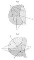
- Fig. 1 presents an overall view of the bladder 1 according to a first aspect of the present invention.
- the bladder 1 as well as the further embodiments discussed below, is arranged within an outer shell of a ball (not shown) and a carcass, if applicable (not shown in fig. 1).
- a suitable coating such that the bladder 1 itself can be used as a ball without needing a separate outer shell.
- planar surfaces 10 are arranged within the bladder which divide the spherical volume of the bladder 1 into several chambers 20.
- An electronic device 30, which is only schematically shown, is arranged at the intersection of the surfaces 10 and is thereby positioned essentially in the center of the bladder 1.
- several electronic devices for example several redundant transmitters, which are symmetrically distributed on planar surfaces around the center of the bladder, in order to increase the reliability against a failure.
- antennas or similar function elements may be distributed among the reinforcement elements 10, pulling elements 60, mounting cables 310 or the like, being explained in the following. It is also conceivable to distribute one or more antennas on the outer surface of the bladder.
- Fig. 4 shows an alternative embodiment with a greater number of reinforcing surfaces 10. It can be seen that the lines 13 along which reinforcing surfaces 10 contact the outer surface 2 of the bladder 1, only a part of which is shown, correspond essentially to the shape of at least one panel of the outer shell of the ball to be inflated, for example the shape of the well-known pentagonal panels.
- openings 21 between the various chambers 20 This allows an equalization of pressure and the oscillation of the device 30 around its starting position is dampened by the flow of air from one chamber 20 into another. This is similar to the function of an oil-pressure bumper in a motor vehicle, wherein oil flows through a small opening from one chamber of the bumper into another to dampen any oscillating movements.
- this effect can be influenced by the size of the openings 21 between the chambers 20. Preferred positions for the openings 21 are: (i) the intersections 12 of the lines 13 at the outer side of the bladder; or (ii) approximately the center of a reinforcing surface 10 as schematically shown in Fig. 4.
- the damping effect can be influenced by the viscosity of the gas which is used to inflate the bladder 1.
- FIG. 2 A comparison of Figs. 2 and 3 discloses a further aspect.
- the electronic device 30 is directly arranged at the intersection of six reinforcing surfaces 10.
- the embodiment of Fig. 3 by contrast, comprises four additional auxiliary surfaces 40, two of which can be recognized in Fig. 3.
- the auxiliary surfaces 40 form a separate volume around the intersection of the six reinforcing surfaces 10 where the electronic device 30 is arranged. This provides for additional possibilities to protect the electronic device 30 (not shown in Fig. 3) against damages.
- auxiliary surfaces 40 it is e.g. conceivable to fill the volume defined by the auxiliary surfaces 40 with a foam or the like for avoiding damages, if the instep of a player penetrates in case of a very sharp shot deeply into the interior of the ball and the bladder 1.
- the inner volume is filled by a gas having a particularly high pressure to avoid deformations.
- the auxiliary surfaces 40 further contribute to the stabilization of the interior framework of the bladder 1 which is created by the reinforcing surfaces 10.
- the reinforcing surfaces 10, the auxiliary surfaces 40 and the outer surface of the bladder are preferably made from a light-weight but tear resistant material which can be brought into the desired shape by thermal molding. Particularly preferred is the use of a thin film made from a thermoplastic urethane (TPU).
- TPU thermoplastic urethane
- the thickness of the used TPU, its material properties and suitable treatment steps in production, if applicable, such as a pre-expansion of the film, may change the dynamic properties of the bladder 1 over far ranges.
- Such reinforced TPU films are offered e.g. by the company Elastogran GmbH.
- Figures 16a and 16b illustrate the influence of different material thicknesses on the bladder's dynamic behavior.
- the diagrams show the dynamic behavior of a bladder with tetrahedral reinforcement surfaces (as shown in fig. 2) in case of an impact at 80 mph (miles per hour). While fig. 16a shows the resulting accelerations on the transmitter in the bladder's interior (in multiples of acceleration of gravity g), fig. 16b shows the deflection of the transmitter. Therein, it was assumed that the transmitter has a total volume of 80 g. One can see immediately that the thickness of the used TPU film has large influence on the response behavior of the bladder. It results from the diagrams that a wall thickness within a range of approx. 1 mm leads to the least deflections at comparatively low acceleration values. A wall thickness of approx. 0.5 mm still supplies good results, whereas a wall thickness of approx. 0.15 mm results in sustained contact with the bladder's outer shell.
- a pre-treatment in particular an expansion of the TPU film prior to its use in the bladder, is shown in fig. 17.
- the shape of the respective hysteresis curve of a deflection cycle instead depends on the largest previous deflection (cf. the sequence red lines for the first expansion, blue lines for the second expansion, and brown lines for the third expansion). Then, the increase of the new hysteresis curve substantially coincides with the return path of the hysteresis curve of this previous deflection.
- the TPU film in the bladder sags after a strong deformation or a large acceleration of the ball.
- one or more mounting cables 310 or the like are integrated into the reinforcement surfaces 10, which are capable of receiving significant tensile strengths, and which are directly or indirectly attached at their one end to the electronic component 30 and at the other end to a carcass 300 of the ball, surrounding the bladder 1.
- Including the carcass 300 in the suspension of the electronic component further increases the stability of the anchorage of the electronic component 30 in the ball's interior.
- the mounting cable 310 is positioned between two partial surfaces of the reinforcing surface 10. It is possible to enable a relative movement between the partial surfaces and the mounting cable 310 as well as to stationarily anchor the mounting cable 310, e.g. by adhering, heat-sealing, etc. In a simpler embodiment of the concept of fig. 5 (not shown), only one partial surface is provided and the cable 310 is anchored thereto, e.g. by suitable loops or passage through corresponding holes. Adherence with the reinforcement surface 10 is also possible in this case.
- electric lines may also be integrated in one or more cables, be it for charging the above-mentioned accumulator of the transmitter 30 or be it for guiding data to the outside. Since the cable 310 penetrates the bladder 1 to the outside in any case (cf fig. 5), no additional passages are required if the transmitter 30 is to be supplied with power or if communication with it is desired.
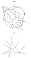
- Figs. 6 and 7 relate to a further aspect of the present invention.
- the electronic device is arranged within a chamber 50 in the center of the bladder 1.
- the chamber 50 provides an additional protection for the electronic device 30.
- the chamber is made from a sufficiently stiff material, for example a light-weight but rigid plastic material, it provides protection for the sensitive components of the electronic device already during assembly of the bladder according to the invention.
- Preferred plastic materials are thermoplastic urethane (TPU) and in particular acrylnitrile-butadiene-styrole (ABS), which can e.g. be obtained under the name TERLURAN®.
- Fig. 6 shows a simplified embodiment, wherein the chamber 50 is formed by interconnecting surfaces 51 between several pulling elements 60, which define the position of the chamber 50 and thereby the device 30 in the center of the bladder 1.
- the interconnecting surfaces 51 have a size so that more than a third of the preferably radially arranged pulling elements 60 is within the chamber 50 or replaced by the chamber 50.
- the overall framework for the suspension of the electronic device is significantly reinforced in its center. Smaller embodiments of the interconnecting surfaces 51, leading to a smaller chamber 50, are, however, also conceivable.
- FIG. 7 A presently preferred modification is shown in Fig. 7.
- An essentially spherical chamber 50 is arranged in the center of the bladder 1, which houses the electronic device (not shown).
- the chamber 50 can be sealed with respect to the interior of the bladder 1. This is particularly advantageous if the chamber 50 is arranged in the interior of the bladder 1 prior to the final manufacturing step of the bladder 1. The influence of aggressive gases or high temperatures on the sensitive components of the electronic device is thereby at least reduced.
- the preferred spherical shape of the chamber 50 provides a further protection for the electronic device. Impacts, which reach the center of the bladder 1 do not hit a planar side surface but cause in most cases only a lateral deflection of the spherical chamber 50. This reduces the acceleration forces effectively acting on the electronic device 30.
- the radial pulling elements 60 for suspending the chamber 50 in the center of the bladder 1 are preferably made from a bundle of highly stable fibers 61, for example aramide fibers. Contrary to the prior art, e.g. DE 200 04 174 U, it is preferred for the pulling elements 60 to be substantially inelastic or at least not highly elastic. In other words, they do elongate under the forces arising during use. Particularly preferred are fibers made from a copolymer of PPTA (polyparaphenylen-terephtalamide) which can be obtained under the trade name Technora®. Preferably, approx.
- PPTA polyparaphenylen-terephtalamide
- the particular advantage of these fibers is apart from the great tensile strength the high temperature resistance which allows to further process the bladder 1 at temperatures of up to 250°C.
- a further important aspect is the extremely small elongation of these fibers even in case of high tensile strengths.
- the pulling elements are elongated by at most 30% or their initial length, preferably less than 25% and particularly preferably less than 20%.
- Single plys, which make up the bundles and finally the pulling elements 60 can preferably be elongated by less than 20%, particularly preferably by less than 15% of their initial length.
- the tensile strength of the pulling elements 60 is preferably more than 1200 N. This allows to suspend the chamber 50 in the interior of the bladder 1 with a high tension so that in case of a deflection the return to the original position is significantly accelerated, which improves the exactness of the ball's positioning.
- Figs. 19a and 19b illustrate the response behavior of a bladder with tetrahedrically arranged pulling elements with two different impact speeds, namely 60 mph and 80 mph. One sees the clearly higher accelerations at the higher speed (green curves) and the longer contact with the outer surface (panel).
- the number of fibers in a pulling element may be varied as well as their interconnection with each other.
- the use of other fibers than the afore-mentioned aramide fibers with a non-linear expansion behavior is conceivable for selectively influencing the stability of the anchoring of the transmitter.
- a plastic material is preferably injected around the outer and the inner end of the fiber bundle 61 to manufacture a mounting section 62, for example by simply injecting a thickening onto the bundle.
- the pulling element 60 only needs to be guided through an opening 53 of a suitable size for anchoring the pulling element to the spherical chamber 50.
- Conceivable is also to manufacture the chamber 50 out of two or more (half-) shells which are injected around the mounting section 62 and which are clipped to each other or welded after inserting the device 30. As a result, the manufacture of the bladder is significantly facilitated.
- mounting feet 63 are arranged at the ends of the pulling elements 60 opposite to the chamber 50.
- the mounting feet 63 serve for anchoring the chamber 50 and the pulling elements 60 to the outer surface 2 of the bladder 1. This may be achieved by gluing, high frequency welding or other common processing techniques for plastic materials. If the mounting feet 63 are also manufactured from a sufficiently temperature-resistant material, the overall bladder 1 can at first be pre-assembled before it is brought into the desired shape and size by a final molding step.
- Figures 13a - 13d show various presently preferred embodiments of the mounting feet 63 for anchoring the pulling elements 60 on the outer surface 2 of the bladder 1.
- the mounting feet 63 have to comprise a sufficiently large contact surface 65 for the outer surface 2 of the bladder, and on the other hand a support for the respective pulling element 60, guaranteeing tensile strength.
- the pulling element (not shown) is guided around a pin (not shown) in a loop, the pin being arranged in a recess 64 on the contact surface 65 of the mounting foot 63.
- the pin may be made of a sufficiently stabile plastic material or also of a metal to be able to resist highest tensile forces.
- the two loose ends of the tension element 60 (not shown) are in this embodiment fixed to the chamber 50.
- Fig. 13b shows a modification using a button-like insert 67 instead of the (metal) pin, around which the pulling element is guided.
- This embodiment is more advantageous if the mounting foot 63 is completely made of plastic, since the button-like insert 67 has a larger surface for resisting the high tensile stresses.
- Fig. 13c shows a further variant allowing for a simplified production.
- the loop of the pulling element 60 (not shown) is guided through a suitable recess 68 in the contact surface 65 without requiring a further component.
- Fig. 13d shows an embodiment wherein a plastic material is first injected around the end of the pulling element which is then also received by a recess in the contact surface (not perceivable in detail in fig. 13d).
- the production of this variant can be automated particularly simple. Instead of the injection, it is also perceivable to provide a knot at the outer end of the pulling element (not shown), which is received by said recess in the contact surface 65.
- the explained examples for the mounting feet 63 of the pulling element on the bladder can, in a smaller embodiment, also be used for anchoring the chamber 50 at the inner end of the respective pulling element 60. Moreover, the explained mounting feet 63 can also be used if one or more pulling elements 60 extend through the outer surface 2 of the bladder and are anchored on the carcass 300. In all embodiments, it may be purposeful to reinforce the ends of the fibers, which are preferably used for the pulling element.
- the pulling elements 60 are arranged such that they encase by pairs substantially identical angles. In case of four pulling elements, as shown in fig. 7, this leads to a tetrahedral configuration of the pulling elements 60 with an angle of 109.47°. If six pulling elements are used, an angle of 90° results.
- one or more transverse connections between the pulling elements 60 For a further stabilization of the suspension of the transmitter, it is possible to arrange one or more transverse connections between the pulling elements 60.
- One such embodiment is schematically shown in fig. 14. Besides the pulling elements 60, extending radially from the center, one can see a plurality of transverse connections 69.
- a structure similar to a three-dimensional spider web results. The forces occurring during accelerations or deformations of the ball are therefore distributed more evenly to the entire bladder and the ball's response behavior becomes more homogenous.
- Fig. 15 shows a further embodiment.
- at least one pulling element 60 branches off into a plurality of sub-elements 160, extending from the branching point 161 to the outer surface 2 of the bladder.
- the contact point of the tensile load transmitted via the pulling element 60 is distributed to a larger range of the outer surface 2.
- the branching point 161 is close to the outer surface.
- An arrangement in which one or more sub-elements are again branched off is also conceivable.
- the transverse connections may interconnect pulling elements among themselves, or also pulling elements and sub-elements, or sub-elements among themselves.
- an at least substantially symmetrical arrangement is preferred for ensuring even mechanical properties of the ball.
- the split-up at the branching point 161 is particularly simple to realize. In this case, the bundle only has to be divided into separate partial bundles, extending to the outer surface 2 from the branching point 161 in different directions.
- Figure 8 shows a modified version of the embodiment of fig. 7.
- the mounting feet 63 are in this embodiment connected with corresponding mounting surfaces 330 on the inner side of the carcass 300 (cf. arrows in fig. 8), e.g. by adhering, highfrequency welding, or similar techniques.
- the carcass 300 is also included in the suspension of the transmitter in fig. 8 in order to thereby achieve an additional degree of stability.
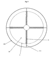
- Figs. 9 and 10 concern a further aspect of the present invention.
- the bladder 1, struts 60' and the chamber 50' are manufactured from a preferably integral piece of material, for example latex.
- the latex can, if necessary, be reinforced by additional fibers and/or a pre-treatment, e.g. an expansion.
- the reinforcing fibers may be added during the production of the latex solution or be introduced later on. It is also conceivable to arrange the fibers at certain positions on the molding tool for the latex solution so that they are embedded into the latex material during its production.
- a latex material with a varying thickness is used in order to locally influence the elastic properties of the bladder 1.
- the bladder 1 comprises a plurality of hollow struts 60' extending from the outer surface 2 of the bladder into its interior and defining a chamber 50'.
- One of the hollow struts 60' comprises a greater diameter for inserting and, if necessary, removing the electronic device 30.
- it is preferably arranged on the opposite side of the receptacle 70 for the valve of the bladder 1.
- an imbalance of the inflated bladder is to a large extent avoided. If the bladder 1 is inflated, the air pressure forces the walls 51' of the chamber 50' against the device 30 and immobilizes it in the center of the bladder 1 without any additional measures.
- gluing or welding is no longer necessary after inserting the electronic device.
- the configuration and the diameter of the hollow struts 60' as well as the chamber 50' in Fig. 9 is only schematic. Other dimensions are also conceivable as well as the arrangement of several chambers 50' to receive more than one electronic device, for example the above-mentioned redundant transmitters.
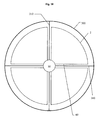
- Fig. 10 shows a modification of the embodiment from fig. 9, wherein the transmitter 30 is fixed to the carcass 300 by means of additional mounting cables 310, extending through the hollow struts 60'.
- This embodiment can also do without any reinforced latex material since the cables 310 can take up sufficient tensile forces to maintain the transmitter 30 in a stable manner in the center of the bladder 1.
- the embodiment of fig. 10 therefore connects aspects of the embodiments from figs. 7 and 8 with the variant of fig. 9.
- Figs. 11 and 12 illustrate a possible apparatus for producing a complex bladder, for example the bladders 1 shown in Figs. 1 - 4.
- several molding components 100 are manufactured from a material with a low melting point, e.g. wax or from a material, dissolving in a suitable liquid, e.g. water or oil.
- the molding components 100 are shaped as segments of a sphere. Using pin-like connections 101, these segments 100 are assembled such that horizontal and vertical gaps 102 are extending through the sphere. From a geometrical viewpoint, the gaps 102 lie in planes defined by a Cartesian coordinate system having its center in the center of the sphere. Other arrangements, in particular for creating the tetrahedral arrangement of the reinforcing elements shown in fig. 2, are also possible.
- an integral bladder 1 is created having reinforcing surfaces in its interior.
- the transmitter (not shown) may either be maintained in its position by the molding components 100 or it is inserted into the finished bladder later on. Due to the pin-like connections 101 there are tube-like interconnections between the segments of the bladder molded around the molding segments 100. As a result, only a single valve connection (not shown) is required for inflating the overall bladder 1.
- Fig. 12 shows an apparatus for maintaining the molding components 100 during molding the bladder 1 in the desired position.
- an outer framework 200 made from metal or plastic strips 201 or the like is used together with wires 202 extending from several directions through the interior of the assembled mold body.
- the wires 202 may serve to hold the transmitter in place during the manufacture of the bladder.
- the wires 202 may during manufacture be integrated into the bladder such that they can subsequently serve as mounting cables 310 to anchor the transmitter in the above described manner to the carcass.
- the outer framework 200 is removed and the bladder including the molding components 100 is heated up to the melting temperature of the used material.
- the liquid material is then removed through the opening for the valve (prior to inserting the valve) by moving the bladder.
- the latter are dissolved by being contacted with a suitable solvent.
Priority Applications (2)
| Application Number | Priority Date | Filing Date | Title |
|---|---|---|---|
| EP08013863A EP1980297B1 (fr) | 2004-09-17 | 2005-09-14 | Vessie |
| EP10175244.2A EP2281610B1 (fr) | 2004-09-17 | 2005-09-14 | Vessie |
Applications Claiming Priority (1)
| Application Number | Priority Date | Filing Date | Title |
|---|---|---|---|
| DE102004045176A DE102004045176B4 (de) | 2004-09-17 | 2004-09-17 | Blase |
Related Child Applications (2)
| Application Number | Title | Priority Date | Filing Date |
|---|---|---|---|
| EP08013863A Division EP1980297B1 (fr) | 2004-09-17 | 2005-09-14 | Vessie |
| EP10175244.2A Division EP2281610B1 (fr) | 2004-09-17 | 2005-09-14 | Vessie |
Publications (2)
| Publication Number | Publication Date |
|---|---|
| EP1637192A1 true EP1637192A1 (fr) | 2006-03-22 |
| EP1637192B1 EP1637192B1 (fr) | 2008-10-15 |
Family
ID=35229817
Family Applications (3)
| Application Number | Title | Priority Date | Filing Date |
|---|---|---|---|
| EP05019996A Active EP1637192B1 (fr) | 2004-09-17 | 2005-09-14 | Vessie |
| EP10175244.2A Active EP2281610B1 (fr) | 2004-09-17 | 2005-09-14 | Vessie |
| EP08013863A Active EP1980297B1 (fr) | 2004-09-17 | 2005-09-14 | Vessie |
Family Applications After (2)
| Application Number | Title | Priority Date | Filing Date |
|---|---|---|---|
| EP10175244.2A Active EP2281610B1 (fr) | 2004-09-17 | 2005-09-14 | Vessie |
| EP08013863A Active EP1980297B1 (fr) | 2004-09-17 | 2005-09-14 | Vessie |
Country Status (6)
| Country | Link |
|---|---|
| US (2) | US7740551B2 (fr) |
| EP (3) | EP1637192B1 (fr) |
| JP (1) | JP4448077B2 (fr) |
| CN (3) | CN101601915B (fr) |
| AT (2) | ATE411089T1 (fr) |
| DE (3) | DE102004045176B4 (fr) |
Cited By (15)
| Publication number | Priority date | Publication date | Assignee | Title |
|---|---|---|---|---|
| EP1872834A2 (fr) * | 2006-06-28 | 2008-01-02 | ESTEFANO, Roberto | Module de connexion pour l'intérieur d'une balle |
| DE102008058943B3 (de) * | 2008-11-25 | 2010-05-12 | Adidas International Marketing B.V. | Blase für einen Ball |
| WO2011036350A1 (fr) * | 2008-09-22 | 2011-03-31 | Universite De Technologie De Troyes | Dispositif d'évaluation et/ou de renforcement de la force de préhension |
| EP2353666A1 (fr) * | 2010-02-08 | 2011-08-10 | Cairos technologies AG | Vessie à ballon supportant un dispositif |
| WO2012150982A1 (fr) * | 2011-03-28 | 2012-11-08 | Physical Apps, Llc | Dispositif d'interaction physique pour dispositifs électroniques individuels et son procédé d'utilisation |
| EP2613852A2 (fr) * | 2010-09-07 | 2013-07-17 | Infomotion Sports Technologies, Inc. | Enceinte de composant électronique pour un objet gonflé |
| US8951106B2 (en) | 2009-03-27 | 2015-02-10 | Infomotion Sports Technologies, Inc. | Monitoring of physical training events |
| EP2945143A1 (fr) * | 2014-05-14 | 2015-11-18 | Adidas AG | Procédés et systèmes de surveillance de mouvement de balle de sport |
| US9298418B2 (en) | 2008-02-14 | 2016-03-29 | Infomotion Sports Technologies, Inc. | Electronic analysis of athletic performance |
| EP3175978A1 (fr) * | 2015-12-01 | 2017-06-07 | Adidas AG | Ballon |
| EP3287175A1 (fr) * | 2017-11-14 | 2018-02-28 | Basu Swati | Vessie de ballon gonflable comportant deux soupapes à double fonction et un composant électronique rechargeable câblé |
| US10076685B2 (en) | 2012-07-02 | 2018-09-18 | Russell Brands, Llc | Operations with instrumented game ball |
| US10523053B2 (en) | 2014-05-23 | 2019-12-31 | Adidas Ag | Sport ball inductive charging methods and systems |
| US10616663B2 (en) | 2012-07-02 | 2020-04-07 | Russell Brands, Llc | Computer-implemented capture of live sporting event data |
| US10702743B2 (en) | 2014-02-28 | 2020-07-07 | Russell Brands, Llc | Data processing inside gaming device |
Families Citing this family (117)
| Publication number | Priority date | Publication date | Assignee | Title |
|---|---|---|---|---|
| IT1331953B1 (it) * | 2002-09-17 | 2006-01-30 | Serena Capriotti | Camera d'aria con sensori elettronici all'interno che rilevano il passaggio del pallone sulla linea di porta anche se coperto da giocatori |
| US20080227696A1 (en) * | 2005-02-22 | 2008-09-18 | Biosurface Engineering Technologies, Inc. | Single branch heparin-binding growth factor analogs |
| US7611429B2 (en) * | 2005-03-01 | 2009-11-03 | Primo Research, Inc. | Inflatable articles that provide long term inflation and pressure control |
| US7520830B2 (en) * | 2005-08-11 | 2009-04-21 | Wong Jacob Y | Game ball |
| US20080242458A1 (en) * | 2007-04-02 | 2008-10-02 | Winn Travis J | Street Soccer Ball |
| JP5142366B2 (ja) * | 2007-10-31 | 2013-02-13 | 学校法人東京電機大学 | 遊戯用ボール |
| US8210973B2 (en) | 2008-06-27 | 2012-07-03 | Nike, Inc. | Sport ball bladder |
| US8192311B2 (en) * | 2008-06-27 | 2012-06-05 | Nike, Inc. | Sport ball with a textile restriction structure |
| US8852039B2 (en) | 2011-06-28 | 2014-10-07 | Nike, Inc. | Sport ball casing with integrated bladder material |
| US8182379B2 (en) | 2008-06-27 | 2012-05-22 | Nike, Inc. | Sport balls and methods of manufacturing the sport balls |
| US8708847B2 (en) | 2008-06-27 | 2014-04-29 | Nike, Inc. | Sport ball casing and methods of manufacturing the casing |
| CA2735879A1 (fr) * | 2008-09-05 | 2010-03-11 | Primo Sport Holdings, Llc | Vessies de latex de neoprene gonflables |
| TW201010760A (en) * | 2008-09-15 | 2010-03-16 | geng-xian Lin | Light-emitting ball |
| DE102008058821B4 (de) * | 2008-11-25 | 2016-01-21 | Adidas International Marketing B.V. | Ballventil und Verfahren zur Herstellung eines Ballventils |
| US9296187B2 (en) * | 2008-12-10 | 2016-03-29 | The Boeing Company | Bagging process and mandrel for fabrication of elongated composite structure |
| US8293051B2 (en) * | 2008-12-10 | 2012-10-23 | The Boeing Company | Method for producing composite laminates using a collapsible mandrel |
| US8029394B2 (en) * | 2009-03-04 | 2011-10-04 | Tachikara Usa, Inc. | Game ball with noise suppression disk |
| US8974330B2 (en) | 2009-03-20 | 2015-03-10 | Nike, Inc. | Sport ball casing and methods of manufacturing the casing |
| US8608599B2 (en) * | 2009-03-20 | 2013-12-17 | Nike, Inc. | Sport ball casing and methods of manufacturing the casing |
| US10668333B2 (en) | 2009-11-19 | 2020-06-02 | Wilson Sporting Goods Co. | Football sensing |
| US9636550B2 (en) | 2009-11-19 | 2017-05-02 | Wilson Sporting Goods Co. | Football sensing |
| US10821329B2 (en) | 2009-11-19 | 2020-11-03 | Wilson Sporting Goods Co. | Football sensing |
| US8870690B2 (en) | 2009-11-19 | 2014-10-28 | Wilson Sporting Goods Co. | American-style football including electronics |
| US10751579B2 (en) | 2009-11-19 | 2020-08-25 | Wilson Sporting Goods Co. | Football sensing |
| US8579743B2 (en) * | 2010-01-05 | 2013-11-12 | Nike, Inc. | Sport balls and methods of manufacturing the sport balls |
| US20110218065A1 (en) * | 2010-03-04 | 2011-09-08 | Cavallaro Richard H | Ball |
| US8617011B2 (en) | 2010-12-03 | 2013-12-31 | Nike, Inc. | Sport ball with indented casing |
| US9370693B2 (en) | 2010-12-03 | 2016-06-21 | Nike, Inc. | Sport ball with indented casing |
| US10363453B2 (en) | 2011-02-07 | 2019-07-30 | New Balance Athletics, Inc. | Systems and methods for monitoring athletic and physiological performance |
| CN103442607B (zh) | 2011-02-07 | 2016-06-22 | 新平衡运动公司 | 用于监视运动表现的系统和方法 |
| US20120244969A1 (en) | 2011-03-25 | 2012-09-27 | May Patents Ltd. | System and Method for a Motion Sensing Device |
| US8672784B2 (en) | 2011-05-04 | 2014-03-18 | Nike, Inc. | Sport ball with an inflation-retention bladder |
| US8771115B2 (en) | 2011-05-04 | 2014-07-08 | Nike, Inc. | Sport ball with an inflation-retention bladder |
| US8597144B2 (en) | 2011-06-28 | 2013-12-03 | Nike, Inc. | Sport ball casing with thermoplastic reinforcing material |
| US9327608B2 (en) | 2011-08-04 | 2016-05-03 | Schneider Electric USA, Inc. | Extendable and deformable carrier for a primary coil of a charging system |
| US20130167290A1 (en) * | 2011-12-30 | 2013-07-04 | Ariel BEN EZRA | Sensor activated ball and sport accessory with computer functionalities |
| US9339691B2 (en) | 2012-01-05 | 2016-05-17 | Icon Health & Fitness, Inc. | System and method for controlling an exercise device |
| JP5005119B1 (ja) * | 2012-01-10 | 2012-08-22 | 真司 葛山 | 球技用透明ボール |
| US8926459B2 (en) | 2012-03-30 | 2015-01-06 | Nike, Inc. | Sport balls and methods of manufacturing the sport balls |
| US9257054B2 (en) | 2012-04-13 | 2016-02-09 | Adidas Ag | Sport ball athletic activity monitoring methods and systems |
| ES2745547T3 (es) | 2012-07-09 | 2020-03-02 | Catapult Group Int Ltd | Seguimiento de pelotas en deportes |
| US10159884B2 (en) | 2012-11-09 | 2018-12-25 | Wilson Sporting Goods Co. | Basketball make-miss shot sensing |
| US9656143B2 (en) | 2012-11-09 | 2017-05-23 | Wilson Sporting Goods Co. | Basketball shot determination system |
| US9844704B2 (en) | 2012-11-09 | 2017-12-19 | Wilson Sporting Goods Co. | Basketball sensing apparatus |
| US9517397B2 (en) | 2012-11-09 | 2016-12-13 | Wilson Sporting Goods Co. | Sport performance system with ball sensing |
| US9656142B2 (en) | 2012-11-09 | 2017-05-23 | Wilson Sporting Goods Co. | Basketball shot determination system |
| US10252118B2 (en) | 2012-11-09 | 2019-04-09 | Wilson Sporting Goods Co. | Basketball with electronics |
| US9724570B2 (en) | 2012-11-09 | 2017-08-08 | Wilson Sporting Goods Co. | Ball lighting |
| US10449421B2 (en) * | 2012-11-09 | 2019-10-22 | Wilson Sporting Goods Co. | Basketball electronics support |
| US9901801B2 (en) | 2012-11-09 | 2018-02-27 | Wilson Sporting Goods Co. | Basketball sensing apparatus |
| US9656140B2 (en) | 2012-11-09 | 2017-05-23 | Wilson Sporting Goods Co. | Sport performance system with ball sensing |
| US10022593B2 (en) * | 2012-11-09 | 2018-07-17 | Wilson Sporting Goods Co. | Basketball having a reduced moment of inertia |
| US9623311B2 (en) | 2012-11-09 | 2017-04-18 | Wilson Sporting Goods Co. | Basketball sensing apparatus |
| US9610746B2 (en) | 2013-02-13 | 2017-04-04 | Adidas Ag | Methods for manufacturing cushioning elements for sports apparel |
| DE102013202485B4 (de) | 2013-02-15 | 2022-12-29 | Adidas Ag | Ball für eine Ballsportart |
| CN103083875B (zh) * | 2013-02-20 | 2014-10-15 | 黑龙江八一农垦大学 | 一种足球 |
| US9500464B2 (en) | 2013-03-12 | 2016-11-22 | Adidas Ag | Methods of determining performance information for individuals and sports objects |
| US9254409B2 (en) | 2013-03-14 | 2016-02-09 | Icon Health & Fitness, Inc. | Strength training apparatus with flywheel and related methods |
| US20140274504A1 (en) * | 2013-03-14 | 2014-09-18 | Russell Brands, Llc | Inflation-Independent Ball with Cover |
| US20140274486A1 (en) | 2013-03-15 | 2014-09-18 | Wilson Sporting Goods Co. | Ball sensing |
| USD776410S1 (en) | 2013-04-12 | 2017-01-17 | Adidas Ag | Shoe |
| US10285899B2 (en) * | 2013-05-13 | 2019-05-14 | Coulter Ventures Llc | Exercise device |
| US9616279B2 (en) * | 2013-05-13 | 2017-04-11 | Coulter Ventures Llc | Exercise device |
| US9833650B2 (en) * | 2013-05-14 | 2017-12-05 | Coulter Ventures Llc | Exercise device |
| US20140357333A1 (en) * | 2013-06-02 | 2014-12-04 | Dan Kevin Canobbio | Gaming apparatus for producing audio-visual signals |
| FR3010909B1 (fr) * | 2013-09-25 | 2015-09-18 | Commissariat Energie Atomique | Dispositif destine a subir des chocs et comprenant des moyens internes piezoelectriques de recuperation d'energie |
| US9403047B2 (en) | 2013-12-26 | 2016-08-02 | Icon Health & Fitness, Inc. | Magnetic resistance mechanism in a cable machine |
| WO2015138339A1 (fr) | 2014-03-10 | 2015-09-17 | Icon Health & Fitness, Inc. | Capteur de pression pour quantifier un travail |
| US10426989B2 (en) | 2014-06-09 | 2019-10-01 | Icon Health & Fitness, Inc. | Cable system incorporated into a treadmill |
| WO2015195965A1 (fr) | 2014-06-20 | 2015-12-23 | Icon Health & Fitness, Inc. | Dispositif de massage après une séance d'exercices |
| US9289657B1 (en) * | 2014-06-24 | 2016-03-22 | Chris Rice | Football with free moving weight |
| US9916001B2 (en) | 2014-07-08 | 2018-03-13 | Wilson Sporting Goods Co. | Sport equipment input mode control |
| CN104117184B (zh) * | 2014-08-11 | 2017-04-12 | 东莞博登运动用品有限公司 | 一种运动球内胆 |
| CN104147764A (zh) * | 2014-09-03 | 2014-11-19 | 洪满 | 一种空气阻力球 |
| WO2016057535A1 (fr) | 2014-10-07 | 2016-04-14 | ShotTracker, Inc. | Filet de basket-ball qui détecte des tirs qui ont été réalisés avec succès |
| US20160238099A1 (en) * | 2015-02-12 | 2016-08-18 | Scott Victor Perino | Advanced Omnidirectional Impact Absorber |
| US10391361B2 (en) | 2015-02-27 | 2019-08-27 | Icon Health & Fitness, Inc. | Simulating real-world terrain on an exercise device |
| EP3090784A1 (fr) * | 2015-04-08 | 2016-11-09 | Amer Sport Italia SpA | Aide à l'entraînement physique |
| CN106178437A (zh) * | 2015-05-04 | 2016-12-07 | 顽石运动智能科技(北京)有限公司 | 一种新型球胆 |
| CN106267744A (zh) * | 2015-05-11 | 2017-01-04 | 顽石运动智能科技(北京)有限公司 | 一种新型球胆 |
| DE102015209811B3 (de) | 2015-05-28 | 2016-12-01 | Adidas Ag | Nicht-aufblasbare Sportbälle |
| DE102015209795B4 (de) | 2015-05-28 | 2024-03-21 | Adidas Ag | Ball und Verfahren zu dessen Herstellung |
| CN105056493B (zh) * | 2015-07-14 | 2017-03-15 | 南京绎霖国际贸易有限公司 | 具有三明治结构的球胆及其制备方法 |
| USD783264S1 (en) | 2015-09-15 | 2017-04-11 | Adidas Ag | Shoe |
| BR112018009299B1 (pt) | 2015-11-10 | 2022-06-28 | Ddsports, Inc | Método para determinar se um jogador marcou um ponto, e, sistema para rastrear jogadores e um objeto de jogabilidade. |
| DE202015008658U1 (de) | 2015-12-21 | 2017-03-22 | Socca360 GmbH | Ball |
| TWM520923U (zh) * | 2016-01-30 | 2016-05-01 | 和碩聯合科技股份有限公司 | 球體 |
| US10625137B2 (en) | 2016-03-18 | 2020-04-21 | Icon Health & Fitness, Inc. | Coordinated displays in an exercise device |
| US10493349B2 (en) | 2016-03-18 | 2019-12-03 | Icon Health & Fitness, Inc. | Display on exercise device |
| US10272317B2 (en) | 2016-03-18 | 2019-04-30 | Icon Health & Fitness, Inc. | Lighted pace feature in a treadmill |
| US10034519B2 (en) | 2016-06-16 | 2018-07-31 | Adidas Ag | UV curable lattice microstructure for footwear |
| USD840136S1 (en) | 2016-08-03 | 2019-02-12 | Adidas Ag | Shoe midsole |
| USD840137S1 (en) | 2016-08-03 | 2019-02-12 | Adidas Ag | Shoe midsole |
| USD852475S1 (en) | 2016-08-17 | 2019-07-02 | Adidas Ag | Shoe |
| JP1582717S (fr) | 2016-09-02 | 2017-07-31 | ||
| CN106310615A (zh) * | 2016-09-21 | 2017-01-11 | 武汉汇动乐智科技有限公司 | 电子足球球体 |
| CN106606844B (zh) * | 2016-09-27 | 2019-08-20 | 简极科技有限公司 | 一种多气囊智能球及其生产工艺 |
| CN106606845A (zh) * | 2016-09-27 | 2017-05-03 | 简极科技有限公司 | 一种双气囊智能球及其生产工艺 |
| US10671705B2 (en) | 2016-09-28 | 2020-06-02 | Icon Health & Fitness, Inc. | Customizing recipe recommendations |
| US9993694B1 (en) * | 2016-12-12 | 2018-06-12 | William J. Warren | Recreational device with rotor assembly |
| CN106422220B (zh) * | 2016-12-27 | 2018-10-23 | 赵红军 | 一种重量可调外形结构稳定的篮球 |
| CN106730666A (zh) * | 2017-02-07 | 2017-05-31 | 广东荣承体育用品制造有限公司 | 智能足球的内胆结构及其制作方法 |
| US10675526B2 (en) | 2017-05-01 | 2020-06-09 | Intel Corporation | Sports apparatus and methods including tracking additives |
| US10029155B1 (en) * | 2017-07-07 | 2018-07-24 | Chien-Chuan LO | Inflatable sports ball having an inner bladder with rib plates |
| USD899061S1 (en) | 2017-10-05 | 2020-10-20 | Adidas Ag | Shoe |
| US10183199B1 (en) | 2017-10-15 | 2019-01-22 | William J. Warren | Tubular projectile device |
| USD839367S1 (en) | 2017-11-23 | 2019-01-29 | William J Warren | Ball for recreational use |
| AU2019244111B2 (en) | 2018-03-27 | 2023-01-19 | Ddsports, Inc. | Wireless charging pod and charging pod rack for game devices with rechargeable batteries |
| EP3557559A1 (fr) | 2018-04-20 | 2019-10-23 | TMRW Foundation IP & Holding S.A.R.L. | Systèmes et procédés de diffusion d'événements sportifs |
| AU2020298144B2 (en) | 2019-06-17 | 2022-05-26 | Ddsports, Inc. | Sports ball with electronics housed in shock-absorbing carrier |
| JP2021045292A (ja) * | 2019-09-17 | 2021-03-25 | 中松 義郎 | 情報ボール |
| TWM590470U (zh) * | 2019-09-23 | 2020-02-11 | 林宜靜 | 感測器定位結構 |
| CN111872015B (zh) * | 2020-06-01 | 2021-06-01 | 许昌学院 | 一种磁脉冲矿化垃圾处理装置 |
| CN111617451A (zh) * | 2020-06-09 | 2020-09-04 | 武汉体育学院 | 一种智能球体内胆 |
| EP4210841A1 (fr) | 2020-09-09 | 2023-07-19 | Wisehockey Oy | Ballon et procédé de fabrication associé |
| CN112370749A (zh) * | 2020-10-28 | 2021-02-19 | 南京群力运动器材有限公司 | 一种波浪篮球制作工艺及波浪篮球 |
| US20240001203A1 (en) * | 2022-07-01 | 2024-01-04 | Adidas Ag | Sports ball with suspension system |
Citations (9)
| Publication number | Priority date | Publication date | Assignee | Title |
|---|---|---|---|---|
| DE829109C (de) * | 1950-11-11 | 1952-01-21 | Friedrich Bartels | Luftgefuellter, duennwandiger Spielball |
| DE1172585B (de) * | 1960-09-02 | 1964-06-18 | Licentia Gmbh | In allen Bewegungsphasen Schall abstrahlender Spielball, insbesondere Spielball fuer den Blindensport |
| US5294112A (en) * | 1993-04-26 | 1994-03-15 | Smith Eldon F | Bladder for use in a sportsball |
| WO1997020449A1 (fr) * | 1995-11-29 | 1997-06-05 | Sound-Ball | Procede pour la restitution des bruits de ballon lors d'une manifestation sportive et ballon pour la mise en oeuvre d'un tel dispositif |
| US5883569A (en) * | 1995-12-12 | 1999-03-16 | Kolefas; Chris | Impact-responsive signal transmitting device |
| WO2001066201A1 (fr) * | 2000-03-06 | 2001-09-13 | Cairos Technologies Ag | Dispositif pour detecter la position et/ou les mouvements d'objets et/ou d'etres vivants |
| JP2004016451A (ja) * | 2002-06-14 | 2004-01-22 | Konami Co Ltd | ボール |
| US20040162170A1 (en) | 2003-02-13 | 2004-08-19 | Wai-Man Ng | Sound and light emitting inflatable ball |
| WO2005044396A2 (fr) * | 2003-10-28 | 2005-05-19 | Helmut Staudt | Balle divisee en compartiments avec moyens de transmission electronique integres |
Family Cites Families (261)
| Publication number | Priority date | Publication date | Assignee | Title |
|---|---|---|---|---|
| US495863A (en) * | 1893-04-18 | whitz | ||
| US360917A (en) * | 1887-04-12 | John book | ||
| FR1488920A (fr) | 1967-10-26 | |||
| US415884A (en) | 1889-11-26 | shibe | ||
| US830582A (en) * | 1905-12-28 | 1906-09-11 | Charles R Fleischman | Inflated ball. |
| US996458A (en) * | 1910-10-24 | 1911-06-27 | Ava R Coleman | Game apparatus. |
| US1187029A (en) | 1916-02-07 | 1916-06-13 | James L Beebout | Basket-ball and similar playing-ball. |
| US1614853A (en) | 1923-06-05 | 1927-01-18 | Schwartz Louis | Ball |
| US1597823A (en) | 1925-04-04 | 1926-08-31 | Randolph Simon | Light-projecting attachment for shoes |
| US1923236A (en) | 1929-04-30 | 1933-08-22 | P Goldsmith Sons Company | Game ball |
| US2078881A (en) | 1933-03-20 | 1937-04-27 | Rohm & Haas | Process for coating rubber and product |
| US2020484A (en) * | 1933-06-15 | 1935-11-12 | Clinton T Turner | Luminous ball |
| US2221534A (en) | 1937-11-06 | 1940-11-12 | Voit | Method of making athletic balls |
| US2653818A (en) | 1949-01-22 | 1953-09-29 | Voit Rubber Corp | Fabric reinforced football |
| US2653817A (en) * | 1949-07-25 | 1953-09-29 | Voit Rubber Corp | Ball tethering device |
| DE1013126B (de) | 1954-07-10 | 1957-08-01 | Continental Gummi Werke Ag | Elastisches Lager fuer Maschinen und Geraete |
| US2760278A (en) | 1955-03-31 | 1956-08-28 | Agrillo Paul | Outsole for ultimate balance and shoe comfort |
| US2897609A (en) | 1956-03-19 | 1959-08-04 | Lawrence E Bodkin | Storage shoe heel |
| US2874964A (en) | 1957-07-09 | 1959-02-24 | Bayshore Ind Inc | Decorative hollow play balls |
| US3119618A (en) | 1959-05-27 | 1964-01-28 | Spalding A G & Bros Inc | Inflated game ball |
| US3112521A (en) | 1961-03-08 | 1963-12-03 | Louis F Muccino | Apparatus for covering golf balls |
| GB933053A (en) | 1961-04-22 | 1963-07-31 | Ignacio Lacruz Abio | Improvements in or relating to balls |
| US3185476A (en) | 1962-08-30 | 1965-05-25 | Walter W Fechner | Spherical ball including an internal resilient hand grip |
| US3229976A (en) * | 1963-03-25 | 1966-01-18 | Jr Walter L Allen | Illuminated beach balls |
| US3508750A (en) | 1964-09-11 | 1970-04-28 | Voit Rubber Corp | Game ball |
| US3616165A (en) * | 1966-05-04 | 1971-10-26 | Tetsuo Nishi | Super-strong cord and tape composed of polyvinyl alcohol fibers |
| US3580575A (en) * | 1967-08-28 | 1971-05-25 | Autotelic Ind Ltd | Game device including selectively impact operable lights |
| DE2125758A1 (en) | 1971-05-25 | 1972-12-07 | Stübbe Maschinenfabrik GmbH, 4925 Kalletal-Kalldorf | Polyurethane foam sports ball - with the appearance dimensions weight and properties of a leather ball |
| FR2215249A1 (en) | 1973-01-25 | 1974-08-23 | Audry Julien | Sports ball with expanded PVC cover - has sewn panels of coated inextensible fabric composite |
| US4065150A (en) | 1976-01-26 | 1977-12-27 | Exxon Research And Engineering Company | Ski and method of making same |
| FR2352649A1 (fr) | 1976-05-25 | 1977-12-23 | Delacoste & Cie | Balle en matiere plastique et procede de fabrication par moulage par rotation |
| BG43028A3 (en) | 1977-04-13 | 1988-04-15 | Gala Np,Cs | Inflatable sport ball and method for its manufacture |
| CA1104601A (fr) * | 1977-05-03 | 1981-07-07 | Peter C. Western | Raccord pour corde de suspension de balle |
| JPS5465638A (en) | 1977-11-02 | 1979-05-26 | Bridgestone Corp | Golf ball with high surface strength |
| US4175446A (en) | 1978-04-26 | 1979-11-27 | The University Of Iowa Research Foundation | Step counting device and method |
| DE2827810C2 (de) * | 1978-06-24 | 1983-03-17 | Zahnradfabrik Friedrichshafen Ag, 7990 Friedrichshafen | Automotive Steuerung für einen hydrostatischen Fahrantrieb |
| FR2443850A1 (fr) | 1978-12-15 | 1980-07-11 | Piraud Robert | Ballon de sport |
| US4333648A (en) | 1979-02-06 | 1982-06-08 | Molten Rubber Industry Co., Ltd. | Inflatable game ball |
| US4261565A (en) | 1980-02-19 | 1981-04-14 | Ideas That Sell, Inc. | Ball and method of making same |
| US4399992A (en) | 1980-03-10 | 1983-08-23 | Questor Corporation | Structural member having a high strength to weight ratio and method of making same |
| US4285846A (en) | 1980-04-28 | 1981-08-25 | Cabot Corporation | Flatted water-reducible coating compositions and method for producing same |
| US4318544A (en) | 1980-10-30 | 1982-03-09 | W. H. Brine Company | Game ball |
| JPS5784068A (en) * | 1980-11-15 | 1982-05-26 | Yunikon Kk | Ball with ball speedometer |
| US4402147A (en) | 1981-05-27 | 1983-09-06 | Chyuan Jong Wu | Shoe having automatic step counter |
| JPS58215335A (ja) | 1982-06-10 | 1983-12-14 | Multi Giken Kk | ボ−ルの製造方法 |
| US4462590A (en) | 1982-10-22 | 1984-07-31 | Figgie International Inc. | Inflatable padded game ball |
| DE3405081A1 (de) | 1984-02-13 | 1985-08-14 | Puma-Sportschuhfabriken Rudolf Dassler Kg, 8522 Herzogenaurach | Sportschuh fuer laufdisziplinen und verfahren zur informationsabgabe und/oder zum informationsaustausch ueber bewegungsablaeufe bei laufdisziplinen |
| JPS60200120A (ja) | 1984-03-24 | 1985-10-09 | Matsushita Electric Works Ltd | 歩数計数器 |
| US4649552A (en) | 1984-03-19 | 1987-03-10 | Matsushita Electric Works, Ltd. | Electronic pedometer with step sensor in removable insole |
| DE3448176C2 (en) | 1984-03-19 | 1988-09-15 | Matsushita Electric Works, Ltd., Kadoma, Osaka, Jp | Electronic step counter |
| US4802671A (en) | 1984-07-05 | 1989-02-07 | Gentiluomo Joseph A | Bowling ball |
| DE3506055A1 (de) | 1985-02-21 | 1986-08-21 | Sachs Systemtechnik Gmbh, 8720 Schweinfurt | Elastische sohle fuer einen schuh |
| FR2572674A1 (fr) | 1985-04-26 | 1986-05-09 | Tassin Charles | Procede de fabrication de corps creux par injection a basse pression autour d'une vessie, fabriquee au prealable |
| US4660831A (en) | 1985-09-16 | 1987-04-28 | Figgie International Inc. | Inflatable padded game ball |
| DE3536803A1 (de) * | 1985-10-16 | 1987-04-16 | Peter Walker | Walker - trainer |
| US4856781A (en) | 1986-01-16 | 1989-08-15 | Molten Corporation | Game ball |
| US4771394A (en) | 1986-02-03 | 1988-09-13 | Puma Aktiengesellschaft Rudolf Dassler Sport | Computer shoe system and shoe for use therewith |
| US4814661A (en) | 1986-05-23 | 1989-03-21 | Washington State University Research Foundation, Inc. | Systems for measurement and analysis of forces exerted during human locomotion |
| DE3643236A1 (de) | 1986-12-18 | 1988-07-07 | Ruhrkohle Ag | Personenschutzfunkgeraet |
| US4798386A (en) | 1986-12-22 | 1989-01-17 | Acushnet Company | Golf ball with fluorescent cover |
| FR2627503B1 (fr) | 1988-02-19 | 1990-08-10 | Adidas Chaussures | Composition pour l'enduction de la surface externe de ballons de sport et ballons ainsi obtenus |
| US4826177A (en) * | 1988-03-31 | 1989-05-02 | Paul Ponte | Ball and game |
| BR8806281A (pt) | 1988-11-25 | 1990-07-24 | Sao Paulo Alpargatas | Sistema de amortecimento de impactos aplicavel em sapatos esportivos |
| FR2643823B1 (fr) | 1989-03-03 | 1992-05-15 | Adidas Chaussures | Ballons de sports ou de loisirs, comprenant une couche externe en mousse a peau integrale et leur obtention |
| IT1226514B (it) | 1989-05-24 | 1991-01-24 | Fila Sport | Calzatura sportiva incorporante, nel tallone, un inserto elastico. |
| DE3918038A1 (de) * | 1989-06-02 | 1990-12-06 | Uhl Sportartikel Karl | Ball, insbesondere fussball |
| US4998734A (en) | 1989-11-30 | 1991-03-12 | Universal Golf Supply, Inc. | Golf ball |
| US5500635A (en) | 1990-02-20 | 1996-03-19 | Mott; Jonathan C. | Products incorporating piezoelectric material |
| US5096756A (en) * | 1990-04-02 | 1992-03-17 | Wilson Sporting Goods Co. | Composite bladder for game balls |
| DE69116261T2 (de) | 1990-08-23 | 1996-06-13 | Casio Computer Co Ltd | Schuh oder Stiefel mit Luftkammern |
| FR2667510B1 (fr) * | 1990-10-09 | 1992-12-24 | Courty Claude | Dispositif destine a la pratique d'un nouveau jeu sportif individuel ou d'equipe. |
| US5091265A (en) | 1991-02-19 | 1992-02-25 | Lisco, Inc. | Coating compositions for game balls |
| US5123659A (en) | 1991-03-01 | 1992-06-23 | Wilson Sporting Goods Co. | Game ball |
| US5179792A (en) | 1991-04-05 | 1993-01-19 | Brantingham Charles R | Shoe sole with randomly varying support pattern |
| US5104126A (en) | 1991-07-08 | 1992-04-14 | Gentiluomo Joseph A | Golf ball |
| US5306450A (en) | 1991-08-13 | 1994-04-26 | The Yokohama Rubber Co., Ltd. | Method of producing wood type golf club head |
| USD360917S (en) | 1991-11-08 | 1995-08-01 | Adidas Sarragan France | Cover segment for a soccer ball |
| WO1993011681A1 (fr) | 1991-12-11 | 1993-06-24 | L.A. Gear, Inc. | Chassure de sport comprenant un module emboitable |
| US5325869A (en) | 1991-12-16 | 1994-07-05 | Stokes Theodore J | Apparatus for load and displacement sensing |
| SE9200257L (sv) | 1992-01-30 | 1993-02-01 | Monica Sjoesvaerd | Halkskydd foer skodon |
| US5357696A (en) | 1992-05-01 | 1994-10-25 | Gray Frank B | Device for measuring force applied to a wearer's foot |
| US5269081A (en) | 1992-05-01 | 1993-12-14 | Gray Frank B | Force monitoring shoe |
| EP0657050B1 (fr) | 1992-07-21 | 2000-11-15 | Hayle Brainpower Pty Ltd. | Systeme et methode de controle d'exercices interactif |
| US5320345A (en) | 1992-10-01 | 1994-06-14 | Wilson Sporting Goods Co. | Game ball with transparent cover |
| DE4233341C2 (de) * | 1992-10-05 | 1997-03-13 | Helmut Staudt | Einrichtung zur Erkennung der Position eines Balles |
| US5383290A (en) | 1992-10-23 | 1995-01-24 | Grim; Tracy E. | Conformable shoe with vacuum formed sole |
| US5471405A (en) | 1992-11-13 | 1995-11-28 | Marsh; Stephen A. | Apparatus for measurement of forces and pressures applied to a garment |
| US5413331A (en) | 1992-12-21 | 1995-05-09 | Oddzon Products, Inc. | Soft reboundable amusement ball and outer skin material |
| US5310178A (en) | 1993-01-29 | 1994-05-10 | Lisco, Inc. | Basketball with polyurethane cover |
| US5303485A (en) | 1993-02-05 | 1994-04-19 | L.A. Gear, Inc. | Footwear with flashing lights |
| US5373651A (en) | 1993-05-03 | 1994-12-20 | Wood; Thomas L. | Smart shoes |
| USD352317S (en) | 1993-06-01 | 1994-11-08 | Guillermo Bassignani | Puzzle |
| US5335188A (en) | 1993-08-10 | 1994-08-02 | Brisson Lawrence J | Bicycle computer with memory and means for comparing present and past performance in real time |
| GB9320034D0 (en) | 1993-09-29 | 1993-11-17 | Umbro Int Ltd | Sports ball |
| US5405469A (en) | 1993-10-15 | 1995-04-11 | Lin; Shen-Lai | Method for forming globe map on rubber basketball |
| JPH07143214A (ja) | 1993-11-19 | 1995-06-02 | Sony Corp | 携帯用電話機 |
| US5644858A (en) | 1993-12-02 | 1997-07-08 | L.A. Gear, Inc. | Inertially responsive footwear lights |
| US5473518A (en) | 1994-02-25 | 1995-12-05 | Haber; Terry M. | Removable flashing light housing for an athletic shoe |
| US6230501B1 (en) | 1994-04-14 | 2001-05-15 | Promxd Technology, Inc. | Ergonomic systems and methods providing intelligent adaptive surfaces and temperature control |
| DE4434889C1 (de) | 1994-05-18 | 1995-04-20 | Obermaier Geb Ohg | Kunststoffball |
| CN2211298Y (zh) | 1994-06-15 | 1995-11-01 | 王荣林 | 无线传声足球 |
| US5890997A (en) | 1994-08-03 | 1999-04-06 | Roth; Eric S. | Computerized system for the design, execution, and tracking of exercise programs |
| US5766707C1 (en) | 1994-09-29 | 2001-04-24 | Obermaier Geb Ohg | Plastic ball |
| US5741195A (en) | 1994-09-30 | 1998-04-21 | Lisco, Inc. | High visibility inflated game ball |
| EP0705624B1 (fr) | 1994-10-05 | 2000-06-28 | Molten Corporation | Balle de jeu et son procédé de fabrication |
| US5490338A (en) | 1994-10-31 | 1996-02-13 | Hwang; Wen I. | Fixing structure for lightening circuit on lightening shoe |
| US6539336B1 (en) | 1996-12-12 | 2003-03-25 | Phatrat Technologies, Inc. | Sport monitoring system for determining airtime, speed, power absorbed and other factors such as drop distance |
| US6885971B2 (en) | 1994-11-21 | 2005-04-26 | Phatrat Technology, Inc. | Methods and systems for assessing athletic performance |
| US6266623B1 (en) | 1994-11-21 | 2001-07-24 | Phatrat Technology, Inc. | Sport monitoring apparatus for determining loft time, speed, power absorbed and other factors such as height |
| US8280682B2 (en) | 2000-12-15 | 2012-10-02 | Tvipr, Llc | Device for monitoring movement of shipped goods |
| US7949488B2 (en) | 1994-11-21 | 2011-05-24 | Nike, Inc. | Movement monitoring systems and associated methods |
| US5636146A (en) | 1994-11-21 | 1997-06-03 | Phatrat Technology, Inc. | Apparatus and methods for determining loft time and speed |
| US6516284B2 (en) | 1994-11-21 | 2003-02-04 | Phatrat Technology, Inc. | Speedometer for a moving sportsman |
| US7162392B2 (en) | 1994-11-21 | 2007-01-09 | Phatrat Technology, Inc. | Sport performance systems for measuring athletic performance, and associated methods |
| US5720200A (en) | 1995-01-06 | 1998-02-24 | Anderson; Kenneth J. | Performance measuring footwear |
| US5592759A (en) | 1995-01-26 | 1997-01-14 | Co-Jo Sports, Inc. | Vibrating footwear |
| US5583776A (en) | 1995-03-16 | 1996-12-10 | Point Research Corporation | Dead reckoning navigational system using accelerometer to measure foot impacts |
| US5566479A (en) | 1995-03-21 | 1996-10-22 | Gray; Frank B. | Shoe contruction for use by diabetic persons |
| US6589630B1 (en) | 1995-03-23 | 2003-07-08 | William R. Crow | Performance enhancing shoe components and methods |
| US5793882A (en) | 1995-03-23 | 1998-08-11 | Portable Data Technologies, Inc. | System and method for accounting for personnel at a site and system and method for providing personnel with information about an emergency site |
| US5596652A (en) | 1995-03-23 | 1997-01-21 | Portable Data Technologies, Inc. | System and method for accounting for personnel at a site and system and method for providing personnel with information about an emergency site |
| US5557259A (en) | 1995-04-10 | 1996-09-17 | Musa; John S. | Proximity alert and direction indicator |
| US5672120A (en) | 1995-05-12 | 1997-09-30 | Specialty Materials And Manufacturing Inc. | Golf club head |
| US5500338A (en) * | 1995-05-31 | 1996-03-19 | Eastman Kodak Company | Black and white photographic elements containing release compounds and method of preparing photographic emulsion |
| US5688192A (en) | 1995-06-07 | 1997-11-18 | Acushnet Company | Solid construction golf ball incorporating compressible materials |
| IT1282155B1 (it) | 1995-06-20 | 1998-03-16 | Sadler Sas Di Marc Sadler & C | Calzatura con suola provvista di dispositivo ammortizzatore |
| US5775005A (en) | 1995-06-21 | 1998-07-07 | Wolverine World Wide Inc. | Footwear sole with cleated window |
| US5640786A (en) | 1995-07-05 | 1997-06-24 | Buyayez; Taher | Monitored footwear with step counter and speedometer display |
| US5931763A (en) | 1995-10-05 | 1999-08-03 | Technogym S.R.L. | System for programming training on exercise apparatus or machines and related method |
| US6183425B1 (en) | 1995-10-13 | 2001-02-06 | The United States Of America As Represented By The Administrator Of The National Aeronautics And Space Administration | Method and apparatus for monitoring of daily activity in terms of ground reaction forces |
| FR2752117B1 (fr) * | 1996-08-01 | 2000-06-16 | Goetgheluck Pascal | Procede pour la restitution des bruits de ballon lors d'une manifestation sportive et ballon pour la mise en oeuvre d'un tel dispositif |
| US5688198A (en) | 1995-12-01 | 1997-11-18 | Dana S. Teifert | Decorative baseball and method of making the same |
| US5655316A (en) | 1995-12-11 | 1997-08-12 | Raymond Hwang | Shoe with weighing and step counting means |
| US5724265A (en) | 1995-12-12 | 1998-03-03 | Hutchings; Lawrence J. | System and method for measuring movement of objects |
| US5639076A (en) * | 1996-01-03 | 1997-06-17 | Counter Punch Group | Lighted inflatable device with long battery life |
| US5574432A (en) | 1996-01-04 | 1996-11-12 | Mccarthy; Steven R. | Apparatus attachable to a shoe for deploying a rescue signal |
| FR2743701A1 (fr) | 1996-01-19 | 1997-07-25 | Suntech | Dispositif absorbeur de chocs et vibrations pour chaussure ou assimile chaussure |
| US5611540A (en) * | 1996-02-09 | 1997-03-18 | Williams; Sean P. | Tethered ball apparatus |
| US5813142A (en) | 1996-02-09 | 1998-09-29 | Demon; Ronald S. | Shoe sole with an adjustable support pattern |
| TW394675B (en) | 1996-06-17 | 2000-06-21 | Huang Ying Jiun | Automatic inflatable air cushion |
| US5970631A (en) | 1996-07-23 | 1999-10-26 | Artemis Innovations Inc. | Footwear for grinding |
| US5748087A (en) | 1996-08-01 | 1998-05-05 | Ingargiola; Thomas R. | Remote personal security alarm system |
| WO1998010358A1 (fr) | 1996-09-04 | 1998-03-12 | Goldberg David A | Obtention d'images specifiques de personnes dans un lieu public |
| CA2218242C (fr) | 1996-10-11 | 2005-12-06 | Kenneth R. Fyfe | Systeme d'analyse de mouvement |
| US6012822A (en) | 1996-11-26 | 2000-01-11 | Robinson; William J. | Motion activated apparel flasher |
| US5772545A (en) | 1996-12-20 | 1998-06-30 | Ou; Tsung Ming | Sportsball and manufacturing method thereof |
| US5759123A (en) | 1996-12-24 | 1998-06-02 | Ou; Tsung Ming | Sewing rubber american football and manufacturing method therof |
| FI103083B1 (fi) | 1997-01-20 | 1999-04-15 | Nokia Telecommunications Oy | Pakettiradioverkko ja menetelmä reititysalueen päivittämiseksi |
| US5711725A (en) | 1997-01-23 | 1998-01-27 | Bengtson; Timothy A. | Practice baseball/softball with contrasting colors |
| DE29701308U1 (de) | 1997-01-28 | 1997-05-15 | Schiebl Frank Dipl Sportlehrer | Bewegungsmeßgerät zur Erfassung der Bewegung des Fußes im Schuh |
| US5725445A (en) * | 1997-02-28 | 1998-03-10 | Kennedy; Melvin | Flashing light pneumatic playball |
| CA2199458C (fr) | 1997-03-07 | 2000-06-27 | Tien-Tsai Huang | Chaussure a comptage electronique des pas |
| US6245862B1 (en) | 1997-03-13 | 2001-06-12 | Acushnet Company | Golf balls comprising sulfonated or phosphonated ionomers |
| US5865697A (en) | 1997-03-24 | 1999-02-02 | Lisco, Inc. | Sports ball with improved feel |
| US6312361B1 (en) | 1997-04-16 | 2001-11-06 | Kenneth Scott Hayes | Synthetic sand frontal training shoe |
| US5755634A (en) | 1997-05-19 | 1998-05-26 | Huang; Tien-Tsai | Inflatable ball with a digital pressure display |
| US6014080A (en) | 1998-10-28 | 2000-01-11 | Pro Tech Monitoring, Inc. | Body worn active and passive tracking device |
| DE19732824C2 (de) * | 1997-07-30 | 1999-08-19 | Adidas Int Bv | Fußball |
| DE19758546C2 (de) | 1997-07-30 | 2003-11-27 | Adidas Int Marketing Bv | Fußball |
| US5983529A (en) | 1997-07-31 | 1999-11-16 | Vans, Inc. | Footwear shock absorbing system |
| US7107706B1 (en) | 1997-08-14 | 2006-09-19 | Promdx Technology, Inc. | Ergonomic systems and methods providing intelligent adaptive surfaces and temperature control |
| US7204041B1 (en) | 1997-08-14 | 2007-04-17 | Promdx Technology, Inc. | Ergonomic systems and methods providing intelligent adaptive surfaces |
| US5929332A (en) | 1997-08-15 | 1999-07-27 | Brown; Norma | Sensor shoe for monitoring the condition of a foot |
| US5918502A (en) | 1997-09-03 | 1999-07-06 | Face International Corporation | Footwear incorporating piezoelectric spring system |
| CN1241144A (zh) | 1997-09-22 | 2000-01-12 | 株式会社宝登 | 球赛用球 |
| US6018705A (en) | 1997-10-02 | 2000-01-25 | Personal Electronic Devices, Inc. | Measuring foot contact time and foot loft time of a person in locomotion |
| US6611789B1 (en) | 1997-10-02 | 2003-08-26 | Personal Electric Devices, Inc. | Monitoring activity of a user in locomotion on foot |
| US6876947B1 (en) | 1997-10-02 | 2005-04-05 | Fitsense Technology, Inc. | Monitoring activity of a user in locomotion on foot |
| US6493652B1 (en) | 1997-10-02 | 2002-12-10 | Personal Electronic Devices, Inc. | Monitoring activity of a user in locomotion on foot |
| US6560903B1 (en) | 2000-03-07 | 2003-05-13 | Personal Electronic Devices, Inc. | Ambulatory foot pod |
| US6882955B1 (en) | 1997-10-02 | 2005-04-19 | Fitsense Technology, Inc. | Monitoring activity of a user in locomotion on foot |
| US6122340A (en) | 1998-10-01 | 2000-09-19 | Personal Electronic Devices, Inc. | Detachable foot mount for electronic device |
| US6298314B1 (en) | 1997-10-02 | 2001-10-02 | Personal Electronic Devices, Inc. | Detecting the starting and stopping of movement of a person on foot |
| US6336365B1 (en) | 1999-08-24 | 2002-01-08 | Personal Electronic Devices, Inc. | Low-cost accelerometer |
| US5888157A (en) | 1997-10-03 | 1999-03-30 | Wilson Sporting Goods Co. | Football |
| US5875571A (en) | 1997-11-06 | 1999-03-02 | Huang; Tien-Tsai | Insole pad having step-counting device |
| US6148271A (en) | 1998-01-14 | 2000-11-14 | Silicon Pie, Inc. | Speed, spin rate, and curve measuring device |
| US5931752A (en) | 1998-01-15 | 1999-08-03 | Wilson Sporting Goods Co. | Inflatable game ball with laid-in channel or logo |
| US6375612B1 (en) | 1998-03-24 | 2002-04-23 | P. Timothy Guichon | Method and system for monitoring animals |
| US6013007A (en) | 1998-03-26 | 2000-01-11 | Liquid Spark, Llc | Athlete's GPS-based performance monitor |
| US6077193A (en) | 1998-04-03 | 2000-06-20 | Unisen, Inc. | Tracking system for promoting health fitness |
| TW394715B (en) | 1998-05-20 | 2000-06-21 | Kwc Ag | Low pressure chill casting apparatus |
| TW407060B (en) | 1998-05-22 | 2000-10-01 | Molten Corp | Ball for ball game |
| US6099423A (en) | 1999-02-11 | 2000-08-08 | Top Ball Trading Co., Ltd. | Basketball |
| US6160254A (en) | 1999-03-02 | 2000-12-12 | Zimmerman; Michael J. | Devices and methods for indicating loss of shock absorption in a shoe |
| US6396413B2 (en) | 1999-03-11 | 2002-05-28 | Telephonics Corporation | Personal alarm monitor system |
| US7219449B1 (en) | 1999-05-03 | 2007-05-22 | Promdx Technology, Inc. | Adaptively controlled footwear |
| US6997852B2 (en) | 1999-07-08 | 2006-02-14 | Icon Ip, Inc. | Methods and systems for controlling an exercise apparatus using a portable remote device |
| US6278378B1 (en) | 1999-07-14 | 2001-08-21 | Reebok International Ltd. | Performance and entertainment device and method of using the same |
| US6251035B1 (en) * | 1999-07-23 | 2001-06-26 | Hu-Liang Fa | Sound and light effects ball structure |
| US6206795B1 (en) | 1999-07-28 | 2001-03-27 | Tsung Ming Ou | Basketball with cushion layers |
| US6122846A (en) | 1999-08-30 | 2000-09-26 | Frank B. Gray | Force monitoring shoe |
| FR2797776B1 (fr) * | 1999-08-31 | 2002-01-04 | Casimir Butryn | Balle plus que rebondissante |
| JP2001143049A (ja) | 1999-09-03 | 2001-05-25 | Auto Network Gijutsu Kenkyusho:Kk | 歩数計測器及び履物 |
| US6813586B1 (en) | 1999-09-07 | 2004-11-02 | Phatrat Technology, Inc. | Event and sport performance methods and systems |
| US6195921B1 (en) | 1999-09-28 | 2001-03-06 | Vinncente Hoa Gia Truong | Virtual intelligence shoe with a podiatric analysis system |
| US20020091796A1 (en) | 2000-01-03 | 2002-07-11 | John Higginson | Method and apparatus for transmitting data over a network using a docking device |
| SE518382C2 (sv) | 2000-01-18 | 2002-10-01 | Leif Nyfelt | Förfarande vid övervakning av en individs rörelser i byggnader och rum |
| ITMI20000086A1 (it) | 2000-01-25 | 2001-07-25 | Stefcom Spa | Struttura di suola ammortizzante |
| JP2001238702A (ja) | 2000-02-28 | 2001-09-04 | Masatoshi Baba | コンピュータ制御エアクッシヨン靴 |
| DE20004174U1 (de) * | 2000-03-06 | 2001-07-19 | Braun Hartmut | Spielgerät, Einrichtung zur Erfassung des Spielgeräts sowie Teile dieser Einrichtung |
| EP1134555A1 (fr) | 2000-03-10 | 2001-09-19 | In2Sports B.V. | Méthode pour déterminer la vitesse et la distance parcourue d'un piéton |
| FR2806922A1 (fr) | 2000-03-31 | 2001-10-05 | Pascal Goetgheluck | Dispositif d'acquisition de donnees concernant l'etat dynamique d'au moins un accessoire de sport |
| KR200201418Y1 (ko) | 2000-04-17 | 2000-11-01 | 권해붕 | 바닥재(밑창) 경사가 조정되는 골프화 |
| US6430843B1 (en) | 2000-04-18 | 2002-08-13 | Nike, Inc. | Dynamically-controlled cushioning system for an article of footwear |
| US6825777B2 (en) | 2000-05-03 | 2004-11-30 | Phatrat Technology, Inc. | Sensor and event system, and associated methods |
| JP2002083116A (ja) | 2000-06-20 | 2002-03-22 | Disparce Inc | ネットワークを利用した顧客情報収集方法、顧客情報提供方法、ポイント付与方法、商品情報提供方法、顧客情報収集装置 |
| US20030009308A1 (en) | 2000-06-24 | 2003-01-09 | Chris Kirtley | Instrumented insole |
| US6875241B2 (en) | 2000-06-30 | 2005-04-05 | Roland J. Christensen, As Operating Manager Of Rjc Development Lc, General Partner Of The Roland J. Christensen Family Limited Partnership | Variable resistance cell |
| JP3816729B2 (ja) | 2000-07-04 | 2006-08-30 | ダイハツ工業株式会社 | リヤサスペンション |
| US6600407B2 (en) | 2000-07-20 | 2003-07-29 | Speedchip Co., Ltd. | Record measurement method and system using radio frequency identification |
| US20020077883A1 (en) | 2000-09-29 | 2002-06-20 | Lancos Kenneth J. | System and method for accumulating marketing data from guests at a coverage area |
| US6424264B1 (en) | 2000-10-12 | 2002-07-23 | Safetzone Technologies Corporation | System for real-time location of people in a fixed environment |
| DE10055289B4 (de) * | 2000-11-08 | 2006-07-27 | Fraunhofer-Gesellschaft zur Förderung der angewandten Forschung e.V. | System zur Bestimmung der Position eines Objekts |
| US6747562B2 (en) | 2001-11-13 | 2004-06-08 | Safetzone Technologies Corporation | Identification tag for real-time location of people |
| US20020080198A1 (en) | 2000-11-14 | 2002-06-27 | Safetzone Technologies Corporation | System for real-time location of people in a fixed environment |
| US6572499B2 (en) | 2000-12-15 | 2003-06-03 | Douglas J. Davies | Versatile play ball |
| AT413784B (de) | 2000-12-21 | 2006-06-15 | Schuster Wilhelm | Einbau-wölb-verwind-stütze |
| US6672991B2 (en) | 2001-03-28 | 2004-01-06 | O'malley Sean M. | Guided instructional cardiovascular exercise with accompaniment |
| US7136826B2 (en) | 2001-04-04 | 2006-11-14 | Koninklijke Philips Electronics N. V. | Method for creating personality profiles using tagged physical objects |
| US7856368B2 (en) | 2001-04-06 | 2010-12-21 | Ahold Licensing Sa | Methods and systems for providing personalized information to users in a commercial establishment |
| US20020156677A1 (en) | 2001-04-18 | 2002-10-24 | Peters Marcia L. | Method and system for providing targeted advertising in public places and carriers |
| US7076441B2 (en) | 2001-05-03 | 2006-07-11 | International Business Machines Corporation | Identification and tracking of persons using RFID-tagged items in store environments |
| US20020174025A1 (en) | 2001-05-17 | 2002-11-21 | Hind John R. | Method and system for providing targeted advertising and personalized customer services |
| US20020173407A1 (en) | 2001-05-18 | 2002-11-21 | Bowman Robert C. | Exercise information system |
| WO2002101512A2 (fr) | 2001-06-12 | 2002-12-19 | Paytronix Systems, Inc. | Systeme de passerelle de paiement de commerçant, de fidelite et d'identification de client |
| CA2451598A1 (fr) | 2001-06-25 | 2003-01-03 | Gregory P. Snyder | Chaussures d'entrainement pour le football |
| US7574363B2 (en) | 2001-08-23 | 2009-08-11 | International Business Machines Corporation | Intelligent merchandise indicator |
| US6634970B2 (en) | 2001-08-30 | 2003-10-21 | Juan M. Jiminez | Basketball with removable rings |
| US6398616B1 (en) * | 2001-09-04 | 2002-06-04 | Motosko, Iii Stephen J. | Inflatable ball with unpredictable movement |
| US6537125B1 (en) * | 2001-09-04 | 2003-03-25 | Motosko, Iii Stephen J. | Inflatable ball with unpredictable movement |
| US6752732B2 (en) | 2001-10-12 | 2004-06-22 | Rawlings Sporting Goods Company, Inc. | Basketball having nine to twelve cover panels |
| GB0128528D0 (en) | 2001-11-29 | 2002-01-23 | Koninkl Philips Electronics Nv | Shoe based force sensor and equipment for use with the same |
| US6614392B2 (en) | 2001-12-07 | 2003-09-02 | Delaware Capital Formation, Inc. | Combination RFID and GPS functionality on intelligent label |
| USD482418S1 (en) | 2001-12-18 | 2003-11-18 | Cambuci S.A. | Ball |
| DE10201134A1 (de) | 2002-01-08 | 2003-07-10 | Mohammad Nasseri | Verfahren und Vorrichtung zur Messwerterfassung und -auswertung in Schuhen bzw. Schuheinlagen |
| US6592477B1 (en) | 2002-01-28 | 2003-07-15 | Wen Hsiang Yang | Ball having molded and raised seam and leather cover |
| US6677917B2 (en) | 2002-02-25 | 2004-01-13 | Koninklijke Philips Electronics N.V. | Fabric antenna for tags |
| US6796056B2 (en) | 2002-05-09 | 2004-09-28 | Nike, Inc. | Footwear sole component with a single sealed chamber |
| US6807753B2 (en) | 2002-05-13 | 2004-10-26 | Adidas International B.V. | Shoe with tunable cushioning system |
| US20030224885A1 (en) * | 2002-06-04 | 2003-12-04 | Leal Jose E. | Illuminated ball |
| US20040046692A1 (en) | 2002-09-05 | 2004-03-11 | Robson Jack D. | Physical training system |
| IT1331953B1 (it) * | 2002-09-17 | 2006-01-30 | Serena Capriotti | Camera d'aria con sensori elettronici all'interno che rilevano il passaggio del pallone sulla linea di porta anche se coperto da giocatori |
| US6788200B1 (en) | 2002-10-21 | 2004-09-07 | Mitchell W Jamel | Footwear with GPS |
| JP3096006U (ja) | 2003-02-19 | 2003-08-29 | 夢筆 魏 | 靴ランプ構造 |
| US7188439B2 (en) | 2003-03-10 | 2007-03-13 | Adidas International Marketing B.V. | Intelligent footwear systems |
| US7225565B2 (en) | 2003-03-10 | 2007-06-05 | Adidas International Marketing B.V. | Intelligent footwear systems |
| DE20317143U1 (de) | 2003-05-22 | 2004-04-08 | Schmidt, Udo | Heizbare Schuheinlage |
| US20050049092A1 (en) * | 2003-08-27 | 2005-03-03 | Dr. Edwin Lo | Ball Apparatus Having Adaptive Rotational Inertia |
| US7020988B1 (en) | 2003-08-29 | 2006-04-04 | Pierre Andre Senizergues | Footwear with enhanced impact protection |
| US20050101411A1 (en) * | 2003-11-10 | 2005-05-12 | Sharon Stiller | Golf ball locator |
| DE10361826A1 (de) * | 2003-12-30 | 2005-07-28 | Johannes Katz | Sportball, insbesondere Fussball |
| US8360905B2 (en) | 2004-02-02 | 2013-01-29 | Nike, Inc. | Chromatic architecture for sports equipment |
| US20050195094A1 (en) | 2004-03-05 | 2005-09-08 | White Russell W. | System and method for utilizing a bicycle computer to monitor athletic performance |
| US7083296B2 (en) | 2004-05-21 | 2006-08-01 | Chuan-Tai Chiang | Flashing device |
| US7494526B2 (en) | 2004-07-14 | 2009-02-24 | Yavitz Edward Q | Plant protection and growth stimulation by nanoscalar particle folial delivery |
| US7254516B2 (en) | 2004-12-17 | 2007-08-07 | Nike, Inc. | Multi-sensor monitoring of athletic performance |
| DE102005014709C5 (de) | 2005-03-31 | 2011-03-24 | Adidas International Marketing B.V. | Schuh |
| US20070006489A1 (en) | 2005-07-11 | 2007-01-11 | Nike, Inc. | Control systems and foot-receiving device products containing such systems |
| US7520830B2 (en) * | 2005-08-11 | 2009-04-21 | Wong Jacob Y | Game ball |
| US20070033838A1 (en) | 2005-08-15 | 2007-02-15 | Luce Nicola J | Intelligent sneaker insole |
-
2004
- 2004-09-17 DE DE102004045176A patent/DE102004045176B4/de active Active
-
2005
- 2005-08-25 CN CN2009101581523A patent/CN101601915B/zh not_active Expired - Fee Related
- 2005-08-25 CN CN2009101581519A patent/CN101601914B/zh not_active Expired - Fee Related
- 2005-08-25 CN CNB2005100930317A patent/CN100536963C/zh active Active
- 2005-09-14 DE DE602005010353T patent/DE602005010353D1/de active Active
- 2005-09-14 EP EP05019996A patent/EP1637192B1/fr active Active
- 2005-09-14 AT AT05019996T patent/ATE411089T1/de not_active IP Right Cessation
- 2005-09-14 AT AT08013863T patent/ATE485877T1/de not_active IP Right Cessation
- 2005-09-14 EP EP10175244.2A patent/EP2281610B1/fr active Active
- 2005-09-14 EP EP08013863A patent/EP1980297B1/fr active Active
- 2005-09-14 DE DE602005024464T patent/DE602005024464D1/de active Active
- 2005-09-16 US US11/229,483 patent/US7740551B2/en active Active
- 2005-09-20 JP JP2005271561A patent/JP4448077B2/ja active Active
-
2010
- 2010-05-11 US US12/777,391 patent/US8231487B2/en active Active
Patent Citations (9)
| Publication number | Priority date | Publication date | Assignee | Title |
|---|---|---|---|---|
| DE829109C (de) * | 1950-11-11 | 1952-01-21 | Friedrich Bartels | Luftgefuellter, duennwandiger Spielball |
| DE1172585B (de) * | 1960-09-02 | 1964-06-18 | Licentia Gmbh | In allen Bewegungsphasen Schall abstrahlender Spielball, insbesondere Spielball fuer den Blindensport |
| US5294112A (en) * | 1993-04-26 | 1994-03-15 | Smith Eldon F | Bladder for use in a sportsball |
| WO1997020449A1 (fr) * | 1995-11-29 | 1997-06-05 | Sound-Ball | Procede pour la restitution des bruits de ballon lors d'une manifestation sportive et ballon pour la mise en oeuvre d'un tel dispositif |
| US5883569A (en) * | 1995-12-12 | 1999-03-16 | Kolefas; Chris | Impact-responsive signal transmitting device |
| WO2001066201A1 (fr) * | 2000-03-06 | 2001-09-13 | Cairos Technologies Ag | Dispositif pour detecter la position et/ou les mouvements d'objets et/ou d'etres vivants |
| JP2004016451A (ja) * | 2002-06-14 | 2004-01-22 | Konami Co Ltd | ボール |
| US20040162170A1 (en) | 2003-02-13 | 2004-08-19 | Wai-Man Ng | Sound and light emitting inflatable ball |
| WO2005044396A2 (fr) * | 2003-10-28 | 2005-05-19 | Helmut Staudt | Balle divisee en compartiments avec moyens de transmission electronique integres |
Non-Patent Citations (1)
| Title |
|---|
| PATENT ABSTRACTS OF JAPAN vol. 2003, no. 12 5 December 2003 (2003-12-05) * |
Cited By (27)
| Publication number | Priority date | Publication date | Assignee | Title |
|---|---|---|---|---|
| EP1872834A2 (fr) * | 2006-06-28 | 2008-01-02 | ESTEFANO, Roberto | Module de connexion pour l'intérieur d'une balle |
| EP1872834A3 (fr) * | 2006-06-28 | 2009-01-07 | ESTEFANO, Roberto | Module de connexion pour l'intérieur d'une balle |
| US9298418B2 (en) | 2008-02-14 | 2016-03-29 | Infomotion Sports Technologies, Inc. | Electronic analysis of athletic performance |
| ES2384774A1 (es) * | 2008-09-22 | 2012-07-12 | Universite De Technologie De Troyes | Dispositivo de evaluación y/o fortalecimiento de la fuerza de prensión. |
| GB2475659A (en) * | 2008-09-22 | 2011-05-25 | Univ Technologies De Troyes | Device for evaluating and/or reinforcing gripping strength |
| GB2475659B (en) * | 2008-09-22 | 2014-01-08 | Univ Technologies De Troyes | Device for evaluation and/or boosting of grip strength |
| WO2011036350A1 (fr) * | 2008-09-22 | 2011-03-31 | Universite De Technologie De Troyes | Dispositif d'évaluation et/ou de renforcement de la force de préhension |
| US8517869B2 (en) | 2008-11-25 | 2013-08-27 | Adidas International Marketing B.V. | Bladder for a ball |
| DE102008058943B3 (de) * | 2008-11-25 | 2010-05-12 | Adidas International Marketing B.V. | Blase für einen Ball |
| US8951106B2 (en) | 2009-03-27 | 2015-02-10 | Infomotion Sports Technologies, Inc. | Monitoring of physical training events |
| US10532248B2 (en) | 2009-03-27 | 2020-01-14 | Russell Brands, Llc | Monitoring of physical training events |
| EP2353666A1 (fr) * | 2010-02-08 | 2011-08-10 | Cairos technologies AG | Vessie à ballon supportant un dispositif |
| EP2613852A2 (fr) * | 2010-09-07 | 2013-07-17 | Infomotion Sports Technologies, Inc. | Enceinte de composant électronique pour un objet gonflé |
| EP2613852A4 (fr) * | 2010-09-07 | 2014-05-07 | Infomotion Sports Technologies Inc | Enceinte de composant électronique pour un objet gonflé |
| US8730037B2 (en) | 2011-03-28 | 2014-05-20 | Physical Apps, Llc | Physical interaction device for personal electronics and method for use |
| US8836500B2 (en) | 2011-03-28 | 2014-09-16 | Physical Apps, Llc | Physical interaction device for personal electronics and method for use |
| WO2012150982A1 (fr) * | 2011-03-28 | 2012-11-08 | Physical Apps, Llc | Dispositif d'interaction physique pour dispositifs électroniques individuels et son procédé d'utilisation |
| US10076685B2 (en) | 2012-07-02 | 2018-09-18 | Russell Brands, Llc | Operations with instrumented game ball |
| US10616663B2 (en) | 2012-07-02 | 2020-04-07 | Russell Brands, Llc | Computer-implemented capture of live sporting event data |
| US10702743B2 (en) | 2014-02-28 | 2020-07-07 | Russell Brands, Llc | Data processing inside gaming device |
| EP2945143A1 (fr) * | 2014-05-14 | 2015-11-18 | Adidas AG | Procédés et systèmes de surveillance de mouvement de balle de sport |
| US9849361B2 (en) | 2014-05-14 | 2017-12-26 | Adidas Ag | Sports ball athletic activity monitoring methods and systems |
| US10523053B2 (en) | 2014-05-23 | 2019-12-31 | Adidas Ag | Sport ball inductive charging methods and systems |
| EP3175978A1 (fr) * | 2015-12-01 | 2017-06-07 | Adidas AG | Ballon |
| EP3988292A1 (fr) * | 2015-12-01 | 2022-04-27 | adidas AG | Ballon |
| US11701551B2 (en) | 2015-12-01 | 2023-07-18 | Adidas Ag | One material ball |
| EP3287175A1 (fr) * | 2017-11-14 | 2018-02-28 | Basu Swati | Vessie de ballon gonflable comportant deux soupapes à double fonction et un composant électronique rechargeable câblé |
Also Published As
| Publication number | Publication date |
|---|---|
| CN101601915B (zh) | 2012-07-18 |
| CN101601915A (zh) | 2009-12-16 |
| EP1980297A1 (fr) | 2008-10-15 |
| DE602005024464D1 (de) | 2010-12-09 |
| US8231487B2 (en) | 2012-07-31 |
| EP1980297B1 (fr) | 2010-10-27 |
| ATE411089T1 (de) | 2008-10-15 |
| JP2006081912A (ja) | 2006-03-30 |
| CN100536963C (zh) | 2009-09-09 |
| ATE485877T1 (de) | 2010-11-15 |
| EP2281610B1 (fr) | 2017-05-17 |
| CN101601914B (zh) | 2012-11-28 |
| CN1748817A (zh) | 2006-03-22 |
| EP1637192B1 (fr) | 2008-10-15 |
| EP2281610A1 (fr) | 2011-02-09 |
| US20100222165A1 (en) | 2010-09-02 |
| CN101601914A (zh) | 2009-12-16 |
| DE102004045176B4 (de) | 2011-07-21 |
| US7740551B2 (en) | 2010-06-22 |
| DE602005010353D1 (de) | 2008-11-27 |
| US20060063622A1 (en) | 2006-03-23 |
| DE102004045176A1 (de) | 2006-03-30 |
| JP4448077B2 (ja) | 2010-04-07 |
Similar Documents
| Publication | Publication Date | Title |
|---|---|---|
| EP1637192B1 (fr) | Vessie | |
| JP6402139B2 (ja) | 非膨張式スポーツボール | |
| EP3097959B1 (fr) | Ballon et son procédé de fabrication | |
| JP2012533442A (ja) | 繊維複合材およびその製造方法 | |
| US11464270B2 (en) | Rotation damping helmet | |
| US11541287B2 (en) | Club head having balanced impact and swing performance characteristics | |
| JP2016025918A (ja) | 繊維複合材およびその製造方法 | |
| JP4515671B2 (ja) | ラケットフレーム | |
| JP3736678B2 (ja) | ラケットフレーム | |
| WO2001047611A1 (fr) | Procede permettant de localiser la masse dans un manche de club de golf | |
| JPH01190374A (ja) | ゴルフクラブのヘッド | |
| JP4444442B2 (ja) | ラケットフレーム及びその製造方法 | |
| JP4295484B2 (ja) | ラケットフレーム | |
| CN102302843A (zh) | 一种足球胆 | |
| JP3970582B2 (ja) | テニスラケット | |
| JP2000229135A (ja) | ゴルフクラブヘッド | |
| TW214518B (fr) | ||
| JP2005177261A (ja) | ゴルフクラブヘッド | |
| JPH11178950A (ja) | ラケット | |
| JP2004081292A (ja) | ラケットフレーム |
Legal Events
| Date | Code | Title | Description |
|---|---|---|---|
| PUAI | Public reference made under article 153(3) epc to a published international application that has entered the european phase |
Free format text: ORIGINAL CODE: 0009012 |
|
| AK | Designated contracting states |
Kind code of ref document: A1 Designated state(s): AT BE BG CH CY CZ DE DK EE ES FI FR GB GR HU IE IS IT LI LT LU LV MC NL PL PT RO SE SI SK TR |
|
| AX | Request for extension of the european patent |
Extension state: AL BA HR MK YU |
|
| 17P | Request for examination filed |
Effective date: 20060922 |
|
| 17Q | First examination report despatched |
Effective date: 20061019 |
|
| AKX | Designation fees paid |
Designated state(s): AT BE BG CH CY CZ DE DK EE ES FI FR GB GR HU IE IS IT LI LT LU LV MC NL PL PT RO SE SI SK TR |
|
| 17Q | First examination report despatched |
Effective date: 20061019 |
|
| GRAP | Despatch of communication of intention to grant a patent |
Free format text: ORIGINAL CODE: EPIDOSNIGR1 |
|
| GRAS | Grant fee paid |
Free format text: ORIGINAL CODE: EPIDOSNIGR3 |
|
| GRAA | (expected) grant |
Free format text: ORIGINAL CODE: 0009210 |
|
| AK | Designated contracting states |
Kind code of ref document: B1 Designated state(s): AT BE BG CH CY CZ DE DK EE ES FI FR GB GR HU IE IS IT LI LT LU LV MC NL PL PT RO SE SI SK TR |
|
| REG | Reference to a national code |
Ref country code: GB Ref legal event code: FG4D Ref country code: CH Ref legal event code: EP |
|
| REG | Reference to a national code |
Ref country code: IE Ref legal event code: FG4D |
|
| REF | Corresponds to: |
Ref document number: 602005010353 Country of ref document: DE Date of ref document: 20081127 Kind code of ref document: P |
|
| NLV1 | Nl: lapsed or annulled due to failure to fulfill the requirements of art. 29p and 29m of the patents act | ||
| PG25 | Lapsed in a contracting state [announced via postgrant information from national office to epo] |
Ref country code: BG Free format text: LAPSE BECAUSE OF FAILURE TO SUBMIT A TRANSLATION OF THE DESCRIPTION OR TO PAY THE FEE WITHIN THE PRESCRIBED TIME-LIMIT Effective date: 20090115 Ref country code: AT Free format text: LAPSE BECAUSE OF FAILURE TO SUBMIT A TRANSLATION OF THE DESCRIPTION OR TO PAY THE FEE WITHIN THE PRESCRIBED TIME-LIMIT Effective date: 20081015 Ref country code: LT Free format text: LAPSE BECAUSE OF FAILURE TO SUBMIT A TRANSLATION OF THE DESCRIPTION OR TO PAY THE FEE WITHIN THE PRESCRIBED TIME-LIMIT Effective date: 20081015 Ref country code: ES Free format text: LAPSE BECAUSE OF FAILURE TO SUBMIT A TRANSLATION OF THE DESCRIPTION OR TO PAY THE FEE WITHIN THE PRESCRIBED TIME-LIMIT Effective date: 20090126 |
|
| PG25 | Lapsed in a contracting state [announced via postgrant information from national office to epo] |
Ref country code: IS Free format text: LAPSE BECAUSE OF FAILURE TO SUBMIT A TRANSLATION OF THE DESCRIPTION OR TO PAY THE FEE WITHIN THE PRESCRIBED TIME-LIMIT Effective date: 20090215 Ref country code: PL Free format text: LAPSE BECAUSE OF FAILURE TO SUBMIT A TRANSLATION OF THE DESCRIPTION OR TO PAY THE FEE WITHIN THE PRESCRIBED TIME-LIMIT Effective date: 20081015 Ref country code: PT Free format text: LAPSE BECAUSE OF FAILURE TO SUBMIT A TRANSLATION OF THE DESCRIPTION OR TO PAY THE FEE WITHIN THE PRESCRIBED TIME-LIMIT Effective date: 20090316 Ref country code: LV Free format text: LAPSE BECAUSE OF FAILURE TO SUBMIT A TRANSLATION OF THE DESCRIPTION OR TO PAY THE FEE WITHIN THE PRESCRIBED TIME-LIMIT Effective date: 20081015 Ref country code: SI Free format text: LAPSE BECAUSE OF FAILURE TO SUBMIT A TRANSLATION OF THE DESCRIPTION OR TO PAY THE FEE WITHIN THE PRESCRIBED TIME-LIMIT Effective date: 20081015 Ref country code: FI Free format text: LAPSE BECAUSE OF FAILURE TO SUBMIT A TRANSLATION OF THE DESCRIPTION OR TO PAY THE FEE WITHIN THE PRESCRIBED TIME-LIMIT Effective date: 20081015 Ref country code: NL Free format text: LAPSE BECAUSE OF FAILURE TO SUBMIT A TRANSLATION OF THE DESCRIPTION OR TO PAY THE FEE WITHIN THE PRESCRIBED TIME-LIMIT Effective date: 20081015 |
|
| PG25 | Lapsed in a contracting state [announced via postgrant information from national office to epo] |
Ref country code: EE Free format text: LAPSE BECAUSE OF FAILURE TO SUBMIT A TRANSLATION OF THE DESCRIPTION OR TO PAY THE FEE WITHIN THE PRESCRIBED TIME-LIMIT Effective date: 20081015 Ref country code: BE Free format text: LAPSE BECAUSE OF FAILURE TO SUBMIT A TRANSLATION OF THE DESCRIPTION OR TO PAY THE FEE WITHIN THE PRESCRIBED TIME-LIMIT Effective date: 20081015 Ref country code: RO Free format text: LAPSE BECAUSE OF FAILURE TO SUBMIT A TRANSLATION OF THE DESCRIPTION OR TO PAY THE FEE WITHIN THE PRESCRIBED TIME-LIMIT Effective date: 20081015 Ref country code: DK Free format text: LAPSE BECAUSE OF FAILURE TO SUBMIT A TRANSLATION OF THE DESCRIPTION OR TO PAY THE FEE WITHIN THE PRESCRIBED TIME-LIMIT Effective date: 20081015 |
|
| PLBE | No opposition filed within time limit |
Free format text: ORIGINAL CODE: 0009261 |
|
| STAA | Information on the status of an ep patent application or granted ep patent |
Free format text: STATUS: NO OPPOSITION FILED WITHIN TIME LIMIT |
|
| PG25 | Lapsed in a contracting state [announced via postgrant information from national office to epo] |
Ref country code: SE Free format text: LAPSE BECAUSE OF FAILURE TO SUBMIT A TRANSLATION OF THE DESCRIPTION OR TO PAY THE FEE WITHIN THE PRESCRIBED TIME-LIMIT Effective date: 20090115 Ref country code: IT Free format text: LAPSE BECAUSE OF FAILURE TO SUBMIT A TRANSLATION OF THE DESCRIPTION OR TO PAY THE FEE WITHIN THE PRESCRIBED TIME-LIMIT Effective date: 20081015 Ref country code: CZ Free format text: LAPSE BECAUSE OF FAILURE TO SUBMIT A TRANSLATION OF THE DESCRIPTION OR TO PAY THE FEE WITHIN THE PRESCRIBED TIME-LIMIT Effective date: 20081015 |
|
| 26N | No opposition filed |
Effective date: 20090716 |
|
| PG25 | Lapsed in a contracting state [announced via postgrant information from national office to epo] |
Ref country code: SK Free format text: LAPSE BECAUSE OF FAILURE TO SUBMIT A TRANSLATION OF THE DESCRIPTION OR TO PAY THE FEE WITHIN THE PRESCRIBED TIME-LIMIT Effective date: 20081015 |
|
| PG25 | Lapsed in a contracting state [announced via postgrant information from national office to epo] |
Ref country code: MC Free format text: LAPSE BECAUSE OF NON-PAYMENT OF DUE FEES Effective date: 20090930 |
|
| REG | Reference to a national code |
Ref country code: CH Ref legal event code: PL |
|
| REG | Reference to a national code |
Ref country code: IE Ref legal event code: MM4A |
|
| PG25 | Lapsed in a contracting state [announced via postgrant information from national office to epo] |
Ref country code: IE Free format text: LAPSE BECAUSE OF NON-PAYMENT OF DUE FEES Effective date: 20090914 |
|
| PG25 | Lapsed in a contracting state [announced via postgrant information from national office to epo] |
Ref country code: LI Free format text: LAPSE BECAUSE OF NON-PAYMENT OF DUE FEES Effective date: 20090930 Ref country code: CH Free format text: LAPSE BECAUSE OF NON-PAYMENT OF DUE FEES Effective date: 20090930 Ref country code: GR Free format text: LAPSE BECAUSE OF FAILURE TO SUBMIT A TRANSLATION OF THE DESCRIPTION OR TO PAY THE FEE WITHIN THE PRESCRIBED TIME-LIMIT Effective date: 20090116 |
|
| PG25 | Lapsed in a contracting state [announced via postgrant information from national office to epo] |
Ref country code: LU Free format text: LAPSE BECAUSE OF NON-PAYMENT OF DUE FEES Effective date: 20090914 |
|
| PG25 | Lapsed in a contracting state [announced via postgrant information from national office to epo] |
Ref country code: HU Free format text: LAPSE BECAUSE OF FAILURE TO SUBMIT A TRANSLATION OF THE DESCRIPTION OR TO PAY THE FEE WITHIN THE PRESCRIBED TIME-LIMIT Effective date: 20090416 |
|
| PG25 | Lapsed in a contracting state [announced via postgrant information from national office to epo] |
Ref country code: TR Free format text: LAPSE BECAUSE OF FAILURE TO SUBMIT A TRANSLATION OF THE DESCRIPTION OR TO PAY THE FEE WITHIN THE PRESCRIBED TIME-LIMIT Effective date: 20081015 |
|
| PG25 | Lapsed in a contracting state [announced via postgrant information from national office to epo] |
Ref country code: CY Free format text: LAPSE BECAUSE OF FAILURE TO SUBMIT A TRANSLATION OF THE DESCRIPTION OR TO PAY THE FEE WITHIN THE PRESCRIBED TIME-LIMIT Effective date: 20081015 |
|
| REG | Reference to a national code |
Ref country code: FR Ref legal event code: PLFP Year of fee payment: 12 |
|
| REG | Reference to a national code |
Ref country code: FR Ref legal event code: PLFP Year of fee payment: 13 |
|
| REG | Reference to a national code |
Ref country code: FR Ref legal event code: PLFP Year of fee payment: 14 |
|
| PGFP | Annual fee paid to national office [announced via postgrant information from national office to epo] |
Ref country code: FR Payment date: 20200819 Year of fee payment: 16 |
|
| PG25 | Lapsed in a contracting state [announced via postgrant information from national office to epo] |
Ref country code: FR Free format text: LAPSE BECAUSE OF NON-PAYMENT OF DUE FEES Effective date: 20210930 |
|
| PGFP | Annual fee paid to national office [announced via postgrant information from national office to epo] |
Ref country code: GB Payment date: 20230823 Year of fee payment: 19 |
|
| PGFP | Annual fee paid to national office [announced via postgrant information from national office to epo] |
Ref country code: DE Payment date: 20230822 Year of fee payment: 19 |