EP1632150A2 - Schaukasten - Google Patents
Schaukasten Download PDFInfo
- Publication number
- EP1632150A2 EP1632150A2 EP05108213A EP05108213A EP1632150A2 EP 1632150 A2 EP1632150 A2 EP 1632150A2 EP 05108213 A EP05108213 A EP 05108213A EP 05108213 A EP05108213 A EP 05108213A EP 1632150 A2 EP1632150 A2 EP 1632150A2
- Authority
- EP
- European Patent Office
- Prior art keywords
- rack
- case
- cold air
- heater
- main body
- Prior art date
- Legal status (The legal status is an assumption and is not a legal conclusion. Google has not performed a legal analysis and makes no representation as to the accuracy of the status listed.)
- Withdrawn
Links
Images




Classifications
-
- A—HUMAN NECESSITIES
- A47—FURNITURE; DOMESTIC ARTICLES OR APPLIANCES; COFFEE MILLS; SPICE MILLS; SUCTION CLEANERS IN GENERAL
- A47F—SPECIAL FURNITURE, FITTINGS, OR ACCESSORIES FOR SHOPS, STOREHOUSES, BARS, RESTAURANTS OR THE LIKE; PAYING COUNTERS
- A47F3/00—Show cases or show cabinets
- A47F3/04—Show cases or show cabinets air-conditioned, refrigerated
-
- A—HUMAN NECESSITIES
- A47—FURNITURE; DOMESTIC ARTICLES OR APPLIANCES; COFFEE MILLS; SPICE MILLS; SUCTION CLEANERS IN GENERAL
- A47F—SPECIAL FURNITURE, FITTINGS, OR ACCESSORIES FOR SHOPS, STOREHOUSES, BARS, RESTAURANTS OR THE LIKE; PAYING COUNTERS
- A47F3/00—Show cases or show cabinets
- A47F3/04—Show cases or show cabinets air-conditioned, refrigerated
- A47F3/0482—Details common to both closed and open types
- A47F3/0486—Details common to both closed and open types for charging, displaying or discharging the articles
-
- A—HUMAN NECESSITIES
- A47—FURNITURE; DOMESTIC ARTICLES OR APPLIANCES; COFFEE MILLS; SPICE MILLS; SUCTION CLEANERS IN GENERAL
- A47B—TABLES; DESKS; OFFICE FURNITURE; CABINETS; DRAWERS; GENERAL DETAILS OF FURNITURE
- A47B57/00—Cabinets, racks or shelf units, characterised by features for adjusting shelves or partitions
- A47B57/06—Cabinets, racks or shelf units, characterised by features for adjusting shelves or partitions with means for adjusting the height of the shelves
- A47B57/20—Cabinets, racks or shelf units, characterised by features for adjusting shelves or partitions with means for adjusting the height of the shelves consisting of tongues, pins or similar projecting means coacting with openings
-
- A—HUMAN NECESSITIES
- A47—FURNITURE; DOMESTIC ARTICLES OR APPLIANCES; COFFEE MILLS; SPICE MILLS; SUCTION CLEANERS IN GENERAL
- A47F—SPECIAL FURNITURE, FITTINGS, OR ACCESSORIES FOR SHOPS, STOREHOUSES, BARS, RESTAURANTS OR THE LIKE; PAYING COUNTERS
- A47F3/00—Show cases or show cabinets
- A47F3/04—Show cases or show cabinets air-conditioned, refrigerated
- A47F3/0404—Cases or cabinets of the closed type
- A47F3/0408—Cases or cabinets of the closed type with forced air circulation
-
- A—HUMAN NECESSITIES
- A47—FURNITURE; DOMESTIC ARTICLES OR APPLIANCES; COFFEE MILLS; SPICE MILLS; SUCTION CLEANERS IN GENERAL
- A47F—SPECIAL FURNITURE, FITTINGS, OR ACCESSORIES FOR SHOPS, STOREHOUSES, BARS, RESTAURANTS OR THE LIKE; PAYING COUNTERS
- A47F3/00—Show cases or show cabinets
- A47F3/04—Show cases or show cabinets air-conditioned, refrigerated
- A47F3/0404—Cases or cabinets of the closed type
- A47F3/0426—Details
- A47F3/0434—Glass or transparent panels
-
- F—MECHANICAL ENGINEERING; LIGHTING; HEATING; WEAPONS; BLASTING
- F25—REFRIGERATION OR COOLING; COMBINED HEATING AND REFRIGERATION SYSTEMS; HEAT PUMP SYSTEMS; MANUFACTURE OR STORAGE OF ICE; LIQUEFACTION SOLIDIFICATION OF GASES
- F25D—REFRIGERATORS; COLD ROOMS; ICE-BOXES; COOLING OR FREEZING APPARATUS NOT OTHERWISE PROVIDED FOR
- F25D21/00—Defrosting; Preventing frosting; Removing condensed or defrost water
- F25D21/14—Collecting or removing condensed and defrost water; Drip trays
-
- A—HUMAN NECESSITIES
- A47—FURNITURE; DOMESTIC ARTICLES OR APPLIANCES; COFFEE MILLS; SPICE MILLS; SUCTION CLEANERS IN GENERAL
- A47B—TABLES; DESKS; OFFICE FURNITURE; CABINETS; DRAWERS; GENERAL DETAILS OF FURNITURE
- A47B57/00—Cabinets, racks or shelf units, characterised by features for adjusting shelves or partitions
- A47B57/30—Cabinets, racks or shelf units, characterised by features for adjusting shelves or partitions with means for adjusting the height of detachable shelf supports
- A47B57/40—Cabinets, racks or shelf units, characterised by features for adjusting shelves or partitions with means for adjusting the height of detachable shelf supports consisting of hooks coacting with openings
Definitions
- the present invention relates to a showcase which comprises a display room surrounded with a transparent wall.
- the showcase of such a type has conventionally been constituted in a manner that by mounting a left/right and rear transparent wall and a front transparent door (transparent wall) to support pillars erected at four corners of a main body, the display room surrounded with the transparent walls is constituted on the main body. Then, a structure has been employed in which a rack for displaying goods is hung in the display room, and cold air is discharged from one side of the main body, the cold air is sucked from the other side to circulate in the display room, thereby cooling the display room to a predetermined temperature (e.g., Japanese Patent Application Laid-Open No. 5-203332).
- a predetermined temperature e.g., Japanese Patent Application Laid-Open No. 5-203332
- a hot and cold type showcase has been constituted in a manner that by mounting a heater to the rack and disposing dampers in both sides of the rack. Then, only the part over the rack in the display room can be warmed up by turning on the heater in the state which the cold air circulation over the rack is shut out by the damper.
- the rack In the showcase which comprises the display room surrounded with the transparent walls, usually the rack is made of wires, and the rack is hung in the display room by engaging the tip of the wires which protrude backward from the rack with the engaging holes of the rack supporting portions mounted to the pillars. As other structures, the rack is received by rack receiving members which are made of resin and engaged with the engaging holes.
- the present invention has been made to solve the aforementioned conventional technical problems, and it is an object of the invention to provide a showcase comprises a display room surrounded with a transparent wall, and reducing the costs of rack hanging structure in the display room.
- a first aspect of the invention is directed to a showcase comprising a display room surrounded with a transparent wall supported by support pillars erected at four corners of a main body; a rack supporting portion having two or more engaging holes and mounted to the pillar; a rack for displaying commercial goods hung in the display room by being supported by the rack supporting portion; a rack receiving member for receiving the rack by engaging with the engaging hole of the rack supporting portion, wherein the rack receiving member is made by bending a metal plate and has an engaging portion made by contact bending of the metal plate which is inserted into and engaged with the engaging hole.
- the showcase comprises the display room surrounded with a transparent wall supported by support pillars erected at four corners of a main body, the rack supporting portion having two or more engaging holes and mounted to the pillar, the rack for displaying commercial goods hung in the display room by being supported by the rack supporting portion, and the rack receiving member for receiving the rack by engaging with the engaging hole of the rack supporting portion.
- the rack receiving member is made by bending a metal plate and has an engaging portion made by contact bending of the metal plate which is inserted into and engaged with the engaging hole.
- the manufacturing cost of the rack receiving member can be reduced remarkably, and the costs for hanging the rack can be reduced.
- the engaging portion of the rack receiving member is made by contact bending of the metal plate, strength of the rack receiving member can be maintained and the rack can be supported stably.
- a second aspect of the present invention is directed to the above showcase further comprising a cold air outlet formed on one side of the main body; a cold air inlet formed on the other side of the main body; a heater mounted in the rack; dampers mounted in both sides of the rack to rotate for open and close the cold air passages between the rack and the transparent walls located in both sides of the rack respectively, wherein the damper opens the cold air passage in stood state and closes the cold air passage being rotated to horizontal state, and the damper is supported by the rack receiving member in the horizontal state.
- the showcase further comprises a cold air outlet formed on one side of the main body, a cold air inlet formed on the other side of the main body, a heater mounted in the rack, and dampers mounted in both sides of the rack to rotate for open and close the cold air passages between the rack and the transparent walls located in both sides of the rack respectively.
- the damper opens the cold air passage in stood state and closes the cold air passage being rotated to horizontal state.
- a third aspect of the present invention is directed to the above showcase further comprising two or more racks hung in the display room; an electrical box mounted in machine room formed under the main body; two or more leads that connect the electrical box and the heater of the racks respectively; two or more accommodating portions formed in the main body that accommodate the rest portion of the leads respectively, wherein the rest portion of the lead from the rack hung in the upper position in the display room is accommodated in the accommodating portion near to the electrical box.
- the showcase further comprises two or more racks hung in the display room, an electrical box mounted in machine room formed under the main body; two or more leads that connect the electrical box and the heater of the racks respectively, and two or more accommodating portions formed in the main body that accommodate the rest portion of the leads respectively.
- the leads have enough length for enabling the rack to move, the appearance can be up by accommodating the rest portion of the leads in the accommodating portions.
- the rest portion of the lead from the rack hung in the upper position in the display room is accommodated in the accommodating portion near to the electrical box.
- the length of the rest portion of the leads from each rack accommodated in the accommodating portions can be equal by accommodating the rest portion of the lead from the rack far from the electrical box in the accommodating portion near to the electrical box.
- a fourth aspect of the present invention is directed to the above showcase further comprising an openable door which forms at least one of the transparent walls; a magnet gasket mounted around the inner surface of the door; and a metal reinforcing member mounted to the pillar, wherein the reinforcing member is located in the outer surface of the pillar, and the gasket adheres to the reinforcing member when the door is closed.
- the showcase further comprises an openable door which forms at least one of the transparent walls, a magnet gasket mounted around the inner surface of the door, and a metal reinforcing member mounted to the pillar.
- the reinforcing member is located in the outer surface of the pillar, and the gasket adheres to the reinforcing member when the door is closed.
- the surface to which the gasket adheres is made of the reinforcing member, and it is not necessary to provide a particular metal plate to which the gasket adheres, therefore the structure can be simple and the costs can be reduced.
- Showcase 1 of the embodiments is a so-called desktop hot and cold type showcase (showcase which is changeable to cooled or warmed state) which is installed at a store such as a convenience store to sell plastic-bottled or canned drinks such as coffee or green tea in a cooled or warmed state.
- a store such as a convenience store to sell plastic-bottled or canned drinks such as coffee or green tea in a cooled or warmed state.
- FIG. 1 is a perspective view of the showcase 1 according to an embodiment of the present invention
- FIG. 2 is an expanded horizontal sectional view of the front corner portion of the showcase 1
- FIG. 3 is a perspective view of the inner structure of the showcase 1
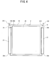
- FIG. 4 is a top view of the rack 2 of the showcase 1
- FIG. 5 is a side view of the rack 2
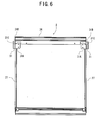
- FIG. 6 is a bottom view of the rack 2
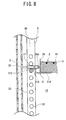
- FIG. 7 and Fig. 8 are elevational views in section of the side part of the rack 2.
- a main body 3 of the showcase 1 of the embodiment comprises an insulated wall (not shown) made of formed polyurethane and a case 6 made of a hard synthetic resin which surrounds the insulated wall.
- front support pillars 7, 7 and rear support pillars 8, 8 are erected at four corners of the main body 3, left and right longitudinal transparent walls 9, 9 made of transparent double glass are supported by the support pillars 7, 7, and 8, 8, and a ceiling wall 11 is mounted on top of the support pillars 7, 7 and 8, 8.
- a longitudinal front and rear doors 12 (front door is shown, rear door is not shown) as a transparent wall in which transparent double glass 12B is fitted into a surrounding sash 12A is pivotally supported by the right front support pillar 7 and the left rear support pillar 8 to rotate.
- a display room 14 is constituted by being surrounded with the transparent walls 9, 9, the doors 12, 12 and the ceiling wall 11.
- the doors 12, 12 close front and rear openings of the display room 14 to be freely opened.
- a reference numeral 15 is a grip mounted to a center front in an up-and down direction (longitudinal direction) of a non-pivotal supporting side (front left side) of the sash 12A.
- a reference numeral 16 is a magnet gasket mounted around the inner surface (pillar 7 or 8 side surface) of the door 12, and bonded to the door 12 to seal it when the door 12 is closed.
- a machine chamber 18 around which grilles 17.. are mounted is constituted below the main body 3 (around the main body 3 is covered with the panel 13 too).
- a compressor and a condenser (not shown) are installed to constitute a refrigerant circuit of a cooling device in the machine chamber 18.
- a cooling chamber (not shown) whose upper surface is open is constituted in the insulated wall of the main body 3.
- An evaporator and a blower (not shown) which constitute the refrigerant circuit are installed in the cooling chamber.
- a cold air outlet 21 is integrally formed from the front to the deep side on the right of the main body 3.
- a cold air inlet 22 is integrally formed from the front to the deep side on the left of the main body 3. The cold air inlet 22 is communicated with a cold air suction side of the evaporator in the cooling chamber, and the cold air outlet 21 is communicated with a cold air discharge side of the evaporator in the cooling chamber.
- each reinforcing member 23 is formed about a gate shape, and integrally mounted to the front surface (outer surface) of the front support pillar 7, 7 and the front surface (outer surface) of the ceiling wall 11, or the rear surface (outer surface) of the rear support pillar 8, 8 and the rear surface (outer surface) of the ceiling wall 11.
- each reinforcing member 23 The bottom ends of each reinforcing member 23 are fixed to the angles (the rear side reinforcing member is not shown).
- the magnet gasket 16 adheres to the reinforcing member 23 when the door 12 is closed.
- the reinforcing member 23 also serves as a surface to which the magnet gasket 16 adheres, therefore it is not necessary to mount a particular metal plate to which the gasket 16 adheres on the outer surface of the support pillars 7, 8.
- the rack 2 comprises a metal upper plate 24, an insulated wall (not shown) inserted in the upper plate 24, a frame member 26 made of resins and mounted around the upper plate 24 and the insulated wall.
- An electric heater H is mounted to an inner surface of the upper plate 24.
- the both sides of the frame member 26 caved in to form a cold air passage between the rack 2 and the transparent walls 9, 9 located in outside of it respectively.
- a damper 27 is mounted respectively (not shown in Fig. 2).
- the damper 27 is mounted by being engaged with front and rear pivots 26A, 26A of the frame member 26 to rotate and move up and down at predetermined range.
- the cold air passages are disposed over the cold air outlet 21 and the cold air inlet 22, and the damper 27 is rotated to open and close the cold air passage.
- Reference numerals 31, 31 are rack receiving members of the present invention for supporting the rack 2.
- This rack receiving member 31 is made by bending a metal plate (steel plate).
- the rack receiving member 31 comprises a receiving portion 31A fixed to the lower surface of the rack 2, an elevated portion 31B which is elevated in a staircase pattern at the out side of the receiving portion 31A, and an engaging portion 31C protrudes backward at the out side of the elevated portion 31B.
- the engaging portion 31C is made by contact bending of the metal plate, and the contact face is in the vertical direction.
- the receiving portion 31A is fixed to the rear corners of the lower surface of the rack 2 by screw for mounting the rack receiving member 31, 31 on the rear both sides of the lower surface of the rack 2.
- the elevated portion 31B is disposed in the outside far from the concave portion of the rack 2, and the damper 27 is positioned between the elevated portion 31B and the rack 2.
- rack supporting portions 8A are formed in the front surface (surface of the display room 14 side) of the rear support pillars 8, 8.
- the rack supporting portion 8A has two or more engaging holes 33.. formed up and down at predetermined intervals.
- Rack supporting portions 7A are formed in the surfaces of the front support pillars 7, 7 facing each other.
- the rack supporting portion 7A has two or more engaging holes 34.. formed up and down in a predetermined interval.
- the engaging portions 31C of the rear both sides rack receiving members 31 are inserted into and engaged with any engaging holes 33, and engaging projections 32 protrude from the both sides of the front end of the rack 2 are inserted into and engaged with the engaging holes 34. In this state, the rack 2 is hung in a state of being inclined low obliquely to the front.
- the rack receiving member 31 is made by bending a metal plate.
- the rack receiving member 31 has an engaging portion 31C made by contact bending of the metal plate which is inserted into and engaged with the engaging hole, and the contact face of the engaging portion 31C is in the vertical direction.
- strength of the rack receiving member 31 against the load of the rack 2 can be maintained and the rack 2 can be supported stably.
- the lowest rack 2 constitutes a deck pan.
- the rack 2 is hung in a state of being inclined low obliquely to the front by being fixed to the front support pillar 7, 7 and the rear support pillar 8, 8 not by above described supporting manner.
- an accommodating groove 36 having a front opening is made in front of the engaging holes 34 of the front support pillar 7, 7.
- the leads 37 from the electric heaters H of the racks 2 are accommodated downwardly in the accommodating groove 36.
- the leads 37 are connected to the electrical box 38 mounted on the rear right corner of the machine chamber 18 for connecting the heaters H of the racks 2 and the electrical box 38 respectively.
- the lead 37 from the highest rack 2 is accommodated in the accommodating groove 36 of the right front support pillar 7, and the lead 37 from the rack 2 under the highest rack 2 is accommodated in the accommodating groove 36 of the left front support pillar 7.
- accommodating portions 41, 41 are integrally formed having upper openings.
- the rest portion of the lead 37 from the highest rack 2 is accommodated in the right side accommodating portion 41, and the rest portion of the lead 37 from the rack 2 under the highest rack 2 is accommodated in the left side accommodating portion 41 (see Fig. 3).
- the entire rest portion was accommodated in the rack, therefore the area of validity of the rack is reduced.
- the highest rack 2 and the rack 2 under the highest rack 2 are movable up and down by changing the engaging holes 33, 34 with which the engaging portion 31C and the engaging projection 32 are engaged.
- the leads 37, 37 have enough length for enabling the highest rack 2 and the rack 2 under the highest rack 2 to move, the rest portion of the leads 37 do not appear in the display room 14 by accommodating the rest portion of the leads 37 in the accommodating portions41 as described above, therefore the appearance can be up.
- the rest portion of the lead 37 from the rack 2 hung in the upper position in the display room (the highest rack 2) is accommodated in the right side accommodating portion 41 near to the electrical box 38.
- the length of the rest portion of the leads 37 from each rack 2 accommodated in the accommodating portions 41 can be equal by accommodating the rest portion of the lead 37 from the rack 2 (the highest rack 2) far from the electrical box 38 in the accommodating portion 41 near to the electrical box 38 (About the lead 37 from the highest rack 2, the distance between the rack 2 and the accommodating portion 41 becomes long. About the lead 37 from the rack 2 under the highest rack 2, the distance between the accommodating portion 41 and the electrical box 38 becomes long).
- the dampers 27, 27 both sides of the highest rack 2 and the rack 2 under the highest rack 2 are rotated to stood state (see Fig. 5, Fig. 6 and Fig. 7).
- the damper 27 is positioned between the elevated portion 31B and the rack 2, and the damper 27 opens the cold air passages between the rack 2 and the transparent walls 9, 9 located in both sides of the rack 2.
- the cold air discharged upward from the cold air outlet 21 goes up in the right side cold air passage of the rack 2, and goes down in the left side cold air passage to be sucked in the cold air inlet 22.
- the whole are in the display room 14 is cooled to a refrigerating temperature.
Landscapes
- Physics & Mathematics (AREA)
- Thermal Sciences (AREA)
- Engineering & Computer Science (AREA)
- Chemical & Material Sciences (AREA)
- Combustion & Propulsion (AREA)
- Mechanical Engineering (AREA)
- General Engineering & Computer Science (AREA)
- Freezers Or Refrigerated Showcases (AREA)
- Refrigerator Housings (AREA)
- Devices That Are Associated With Refrigeration Equipment (AREA)
- Display Racks (AREA)
Applications Claiming Priority (1)
| Application Number | Priority Date | Filing Date | Title |
|---|---|---|---|
| JP2004260092A JP4651333B2 (ja) | 2004-09-07 | 2004-09-07 | ショーケース |
Publications (2)
| Publication Number | Publication Date |
|---|---|
| EP1632150A2 true EP1632150A2 (de) | 2006-03-08 |
| EP1632150A3 EP1632150A3 (de) | 2006-07-12 |
Family
ID=35355090
Family Applications (1)
| Application Number | Title | Priority Date | Filing Date |
|---|---|---|---|
| EP05108213A Withdrawn EP1632150A3 (de) | 2004-09-07 | 2005-09-07 | Schaukasten |
Country Status (6)
| Country | Link |
|---|---|
| US (1) | US20060049726A1 (de) |
| EP (1) | EP1632150A3 (de) |
| JP (1) | JP4651333B2 (de) |
| KR (1) | KR100619194B1 (de) |
| CN (1) | CN100502733C (de) |
| AU (1) | AU2005203653A1 (de) |
Cited By (2)
| Publication number | Priority date | Publication date | Assignee | Title |
|---|---|---|---|---|
| CN102261805A (zh) * | 2011-06-30 | 2011-11-30 | 合肥美的荣事达电冰箱有限公司 | 冰箱 |
| EP4245192A1 (de) | 2022-03-15 | 2023-09-20 | De Rigo Refrigeration S.r.l. | Schaukasten zur konservierung von nahrungsmitteln |
Families Citing this family (18)
| Publication number | Priority date | Publication date | Assignee | Title |
|---|---|---|---|---|
| JP4675078B2 (ja) * | 2004-10-08 | 2011-04-20 | 三洋電機株式会社 | ショーケース |
| US20080000856A1 (en) * | 2006-06-14 | 2008-01-03 | Bernard Primiano | Headroom shelf for a cooler |
| KR200445745Y1 (ko) * | 2007-09-03 | 2009-08-28 | (주)디포그 | 통신기기 랙용 선반 |
| US7971943B2 (en) * | 2007-11-14 | 2011-07-05 | Hatco Corporation | Food display with shelving system |
| KR100948953B1 (ko) * | 2008-02-12 | 2010-03-23 | 주식회사금원하이텍 | 쇼케이스용 선반 지지구조 |
| JP2012065954A (ja) * | 2010-09-27 | 2012-04-05 | Sanyo Electric Co Ltd | 棚装置 |
| CN103653846A (zh) * | 2013-12-05 | 2014-03-26 | 常熟市龙飞物资贸易有限公司 | 一种多功能货架 |
| KR20160059417A (ko) * | 2014-11-18 | 2016-05-26 | 후지 덴키 가부시키가이샤 | 쇼케이스 |
| CN105987571A (zh) * | 2015-02-15 | 2016-10-05 | 青岛海尔股份有限公司 | 双温区搁物板、制冷设备及制冷制热方法 |
| JP6578667B2 (ja) * | 2015-02-18 | 2019-09-25 | 富士電機株式会社 | ショーケース |
| JP6589348B2 (ja) * | 2015-04-15 | 2019-10-16 | 富士電機株式会社 | ショーケース |
| CN104886935A (zh) * | 2015-06-26 | 2015-09-09 | 谢沛君 | 一种可以自由调整层间距的储物柜 |
| US11576500B2 (en) * | 2016-07-13 | 2023-02-14 | Lidl Stiftung & Co. Kg | Temperature control plate and self-service shelf with a temperature control plate |
| JP6262394B1 (ja) * | 2017-08-08 | 2018-01-17 | 株式会社大洋工芸 | 照明付きユニット什器 |
| CN108634603A (zh) * | 2018-05-12 | 2018-10-12 | 芜湖众梦电子科技有限公司 | 一种具有展示功能的3d工艺品制造用存放装置 |
| CN110589318A (zh) * | 2019-09-10 | 2019-12-20 | 厦门博耐特工贸有限公司 | 一种仓储笼货架 |
| GB2631957A (en) * | 2023-07-19 | 2025-01-22 | Illinois Tool Works | A refrigerator appliance |
| US20250207846A1 (en) * | 2023-12-21 | 2025-06-26 | Nashville Wire Products Manufacturing Company, Llc | Cantivlever shelving assembly |
Family Cites Families (30)
| Publication number | Priority date | Publication date | Assignee | Title |
|---|---|---|---|---|
| US298183A (en) * | 1884-05-06 | Terence f | ||
| US987161A (en) * | 1909-09-21 | 1911-03-21 | Martin M Hay | Electric oven. |
| US1295507A (en) * | 1917-12-24 | 1919-02-25 | William T Huening | Display refrigerator-case. |
| US1411260A (en) * | 1920-08-12 | 1922-04-04 | United Alloy Steel Corp | Boltless rack shelving |
| US2611158A (en) * | 1951-05-18 | 1952-09-23 | Eugene J Gregory | Magnetic weatherstrip assembly for thresholds |
| US2758193A (en) * | 1954-06-15 | 1956-08-07 | Mantofel Irving | Display device |
| US2960844A (en) * | 1959-05-27 | 1960-11-22 | Lester K Quick | Refrigerated showcases |
| FR1388765A (fr) * | 1963-11-21 | 1965-02-12 | Vallourec | Assemblages rapides pour des structures légères |
| US3584927A (en) * | 1969-07-10 | 1971-06-15 | Sheldon & Co E H | Biology study enclosure |
| US3674982A (en) * | 1970-11-09 | 1972-07-04 | Rama Ind Heater Co | Zone controlled cook oven |
| US3632968A (en) * | 1970-12-14 | 1972-01-04 | Robert G Wilson | Self-service food warmer assembly |
| FR2137035B1 (de) * | 1971-05-12 | 1973-05-11 | Sebilleau Roger | |
| JPS5811245Y2 (ja) * | 1977-01-29 | 1983-03-02 | サンデン株式会社 | 冷蔵ショ−ケ−ス等の網棚受けの構造 |
| US4346756A (en) * | 1980-08-20 | 1982-08-31 | Uop Inc. | Apparatus for selectively heating an individual food item in a refrigerated environment |
| JPS634929Y2 (de) * | 1981-06-03 | 1988-02-09 | ||
| GB2114874B (en) * | 1982-02-18 | 1985-09-04 | Barton Handling And Storage Sy | Knock-down shelving systems |
| US4744611A (en) * | 1985-04-04 | 1988-05-17 | Sanden Corporation | Display cabinet |
| US4941289A (en) * | 1987-12-10 | 1990-07-17 | Ardco, Inc. | Refrigerator door frame with insulated mullion |
| US4948206A (en) * | 1988-12-02 | 1990-08-14 | Ardco, Inc. | Refrigerator door assembly with decorative front trim panels |
| JPH05203332A (ja) * | 1992-01-24 | 1993-08-10 | Sanyo Electric Co Ltd | 冷却貯蔵庫 |
| US6119587A (en) * | 1995-05-11 | 2000-09-19 | Restaurant Technology, Inc. | Cooked food staging device and method |
| US5662364A (en) * | 1995-06-20 | 1997-09-02 | Reeb; David L. | Latching mechanism for container lid |
| JPH09330467A (ja) * | 1996-06-07 | 1997-12-22 | Sanyo Electric Co Ltd | 自動販売機の商品搬送装置 |
| JPH11270948A (ja) * | 1998-03-20 | 1999-10-05 | Sanden Corp | ショーケース |
| JPH11276316A (ja) * | 1998-03-27 | 1999-10-12 | Sanden Corp | ショーケース |
| JP3543664B2 (ja) * | 1999-03-11 | 2004-07-14 | 住友電装株式会社 | 圧接端子金具 |
| JP4036583B2 (ja) * | 1999-08-31 | 2008-01-23 | 三洋電機株式会社 | 貯蔵庫 |
| JP2002168558A (ja) * | 2000-11-30 | 2002-06-14 | Sanyo Electric Co Ltd | ショーケース |
| JP2003194453A (ja) * | 2001-12-27 | 2003-07-09 | Sanden Corp | ショーケース |
| JP3813889B2 (ja) * | 2002-03-06 | 2006-08-23 | サンデン株式会社 | ショーケースの商品棚 |
-
2004
- 2004-09-07 JP JP2004260092A patent/JP4651333B2/ja not_active Expired - Lifetime
-
2005
- 2005-05-10 KR KR1020050038645A patent/KR100619194B1/ko not_active Expired - Fee Related
- 2005-06-21 CN CNB2005100789827A patent/CN100502733C/zh not_active Expired - Lifetime
- 2005-08-16 AU AU2005203653A patent/AU2005203653A1/en not_active Abandoned
- 2005-09-06 US US11/218,539 patent/US20060049726A1/en not_active Abandoned
- 2005-09-07 EP EP05108213A patent/EP1632150A3/de not_active Withdrawn
Cited By (2)
| Publication number | Priority date | Publication date | Assignee | Title |
|---|---|---|---|---|
| CN102261805A (zh) * | 2011-06-30 | 2011-11-30 | 合肥美的荣事达电冰箱有限公司 | 冰箱 |
| EP4245192A1 (de) | 2022-03-15 | 2023-09-20 | De Rigo Refrigeration S.r.l. | Schaukasten zur konservierung von nahrungsmitteln |
Also Published As
| Publication number | Publication date |
|---|---|
| JP2006075229A (ja) | 2006-03-23 |
| US20060049726A1 (en) | 2006-03-09 |
| AU2005203653A1 (en) | 2006-03-23 |
| CN1745684A (zh) | 2006-03-15 |
| KR100619194B1 (ko) | 2006-09-06 |
| JP4651333B2 (ja) | 2011-03-16 |
| EP1632150A3 (de) | 2006-07-12 |
| KR20060045991A (ko) | 2006-05-17 |
| CN100502733C (zh) | 2009-06-24 |
Similar Documents
| Publication | Publication Date | Title |
|---|---|---|
| EP1632150A2 (de) | Schaukasten | |
| US20100043472A1 (en) | Low temperature showcase | |
| CN101603760B (zh) | 制冷设备 | |
| CN101603761B (zh) | 制冷设备及其箱体制造方法 | |
| US8016136B2 (en) | Showcase | |
| EP3842714B1 (de) | Modulare kühlschrankanordnung | |
| CN101603758B (zh) | 制冷设备及其箱体用隔断 | |
| EP1535543A1 (de) | Schaukasten | |
| JP4097594B2 (ja) | ショーケース | |
| JP4598171B2 (ja) | 棚柱付き冷蔵ショーケース | |
| JPH10220958A (ja) | ショーケース | |
| KR100903140B1 (ko) | 공기조화기 | |
| KR0179880B1 (ko) | 오픈 쇼케이스의 냉기 순환 구조 | |
| JP4141338B2 (ja) | 低温ショーケース | |
| JP3948891B2 (ja) | ショーケース | |
| JP2951106B2 (ja) | 冷却貯蔵庫 | |
| JP5631680B2 (ja) | ショーケース | |
| JP4031883B2 (ja) | 冷蔵庫 | |
| JP2025082379A (ja) | クローズ型冷蔵ショーケース | |
| JP2925972B2 (ja) | 貯蔵庫の排水装置 | |
| KR20210058219A (ko) | 냉장고 | |
| JPH05306878A (ja) | 低温ショーケース | |
| JP2020034212A (ja) | ショーケース | |
| JPH08170874A (ja) | 貯蔵庫等の棚受け部材 | |
| JP2012154586A (ja) | 冷却貯蔵庫 |
Legal Events
| Date | Code | Title | Description |
|---|---|---|---|
| PUAI | Public reference made under article 153(3) epc to a published international application that has entered the european phase |
Free format text: ORIGINAL CODE: 0009012 |
|
| AK | Designated contracting states |
Kind code of ref document: A2 Designated state(s): AT BE BG CH CY CZ DE DK EE ES FI FR GB GR HU IE IS IT LI LT LU LV MC NL PL PT RO SE SI SK TR |
|
| AX | Request for extension of the european patent |
Extension state: AL BA HR MK YU |
|
| PUAL | Search report despatched |
Free format text: ORIGINAL CODE: 0009013 |
|
| AK | Designated contracting states |
Kind code of ref document: A3 Designated state(s): AT BE BG CH CY CZ DE DK EE ES FI FR GB GR HU IE IS IT LI LT LU LV MC NL PL PT RO SE SI SK TR |
|
| AX | Request for extension of the european patent |
Extension state: AL BA HR MK YU |
|
| RIC1 | Information provided on ipc code assigned before grant |
Ipc: A47B 57/40 20060101ALI20060606BHEP Ipc: A47B 57/16 20060101ALI20060606BHEP Ipc: A47F 3/04 20060101AFI20060606BHEP |
|
| 17P | Request for examination filed |
Effective date: 20060809 |
|
| 17Q | First examination report despatched |
Effective date: 20061016 |
|
| AKX | Designation fees paid |
Designated state(s): DE ES FR GB IT |
|
| STAA | Information on the status of an ep patent application or granted ep patent |
Free format text: STATUS: THE APPLICATION IS DEEMED TO BE WITHDRAWN |
|
| 18D | Application deemed to be withdrawn |
Effective date: 20160401 |