EP1591329A1 - Dispositif d'antivol pour véhicules de loisir - Google Patents
Dispositif d'antivol pour véhicules de loisir Download PDFInfo
- Publication number
- EP1591329A1 EP1591329A1 EP20050252595 EP05252595A EP1591329A1 EP 1591329 A1 EP1591329 A1 EP 1591329A1 EP 20050252595 EP20050252595 EP 20050252595 EP 05252595 A EP05252595 A EP 05252595A EP 1591329 A1 EP1591329 A1 EP 1591329A1
- Authority
- EP
- European Patent Office
- Prior art keywords
- vehicle
- transmitter
- receiver
- controller
- signal
- Prior art date
- Legal status (The legal status is an assumption and is not a legal conclusion. Google has not performed a legal analysis and makes no representation as to the accuracy of the status listed.)
- Granted
Links
- 230000002265 prevention Effects 0.000 title claims abstract description 118
- 230000004044 response Effects 0.000 claims description 40
- 230000005540 biological transmission Effects 0.000 claims description 39
- 238000000034 method Methods 0.000 description 59
- 230000008569 process Effects 0.000 description 59
- 230000006870 function Effects 0.000 description 28
- 239000007858 starting material Substances 0.000 description 23
- 238000001514 detection method Methods 0.000 description 15
- 239000000446 fuel Substances 0.000 description 6
- 210000003813 thumb Anatomy 0.000 description 6
- 230000007704 transition Effects 0.000 description 5
- 238000004891 communication Methods 0.000 description 3
- 238000010276 construction Methods 0.000 description 3
- 238000012423 maintenance Methods 0.000 description 2
- 230000007257 malfunction Effects 0.000 description 2
- 238000004519 manufacturing process Methods 0.000 description 2
- 230000004913 activation Effects 0.000 description 1
- 238000010586 diagram Methods 0.000 description 1
- 230000000694 effects Effects 0.000 description 1
- 238000002347 injection Methods 0.000 description 1
- 239000007924 injection Substances 0.000 description 1
- 238000003825 pressing Methods 0.000 description 1
- XLYOFNOQVPJJNP-UHFFFAOYSA-N water Substances O XLYOFNOQVPJJNP-UHFFFAOYSA-N 0.000 description 1
Images


Classifications
-
- B—PERFORMING OPERATIONS; TRANSPORTING
- B60—VEHICLES IN GENERAL
- B60R—VEHICLES, VEHICLE FITTINGS, OR VEHICLE PARTS, NOT OTHERWISE PROVIDED FOR
- B60R25/00—Fittings or systems for preventing or indicating unauthorised use or theft of vehicles
- B60R25/01—Fittings or systems for preventing or indicating unauthorised use or theft of vehicles operating on vehicle systems or fittings, e.g. on doors, seats or windscreens
- B60R25/04—Fittings or systems for preventing or indicating unauthorised use or theft of vehicles operating on vehicle systems or fittings, e.g. on doors, seats or windscreens operating on the propulsion system, e.g. engine or drive motor
-
- B—PERFORMING OPERATIONS; TRANSPORTING
- B60—VEHICLES IN GENERAL
- B60R—VEHICLES, VEHICLE FITTINGS, OR VEHICLE PARTS, NOT OTHERWISE PROVIDED FOR
- B60R25/00—Fittings or systems for preventing or indicating unauthorised use or theft of vehicles
- B60R25/20—Means to switch the anti-theft system on or off
- B60R25/24—Means to switch the anti-theft system on or off using electronic identifiers containing a code not memorised by the user
-
- B—PERFORMING OPERATIONS; TRANSPORTING
- B60—VEHICLES IN GENERAL
- B60R—VEHICLES, VEHICLE FITTINGS, OR VEHICLE PARTS, NOT OTHERWISE PROVIDED FOR
- B60R2325/00—Indexing scheme relating to vehicle anti-theft devices
- B60R2325/30—Vehicles applying the vehicle anti-theft devices
- B60R2325/306—Motorcycles
Definitions
- the present invention relates to a theft prevention apparatus configured to prevent theft (defined to include a loss of a transmitter as well as theft in a general sense) of leisure vehicles such as motor vehicles including motorcycles, three-wheeled vehicles, and four-wheeled vehicles equipped with riders' seats which is open to outside, personal watercraft (PWC), etc.
- theft defined to include a loss of a transmitter as well as theft in a general sense
- leisure vehicles such as motor vehicles including motorcycles, three-wheeled vehicles, and four-wheeled vehicles equipped with riders' seats which is open to outside, personal watercraft (PWC), etc.
- a motorcycle or personal watercraft which are one type of leisure vehicles, is equipped with a rider's seat which is open to outside. So, anyone may freely ride into the rider's seat. In many cases, a rider steers the vehicle, wearing gloves. Therefore, it is difficult for the rider to take out a key from a pocket or the like with a hand wearing the glove.
- a user identification (ID) code is transmitted from a portable transmitter put in the pocket or the like and is received by a receiver equipped in the vehicle.
- a controller built in the vehicle determines whether or not the received code matches a correct user ID code. If it is determined that the received code matches the correct user ID code, the controller configures the vehicle for a start-up condition, whereas if it is determined that the received code does not match the correct user ID code, the controller configures the vehicle to an unsteerable condition.
- a remote-controllable theft prevention apparatus is disclosed in Japanese Laid-Open Patent Application Publication No. 8-120992.
- the leisure vehicle such as the motorcycle or the personal watercraft is equipped with the rider's seat which is open to outside as described above, anyone can ride into the seat. If the rider (owner) carrying the transmitter associated with the vehicle comes closer to a predetermined distance, for example, 10 meters away from the vehicle, then the user ID code matches the correct user ID code, so that someone riding on the seat, other than the rider (owner), may start-up an engine of the vehicle. As a result, there exists a chance of theft of the vehicle.
- the transmitter may fall off of the pocket or the like and may be lost during travel of the vehicle. In that case, if the rider (owner) stops the vehicle and turns off a power supply of the vehicle at a gas station or the like, even the rider (owner) cannot start-up the vehicle again.
- the present invention addresses the above described conditions, and an object of the present invention is to provide a theft prevention apparatus of a leisure vehicle which is capable of quickly detecting a loss of a transmitter configured to transmit a user ID code while a rider is steering the vehicle or pushing the vehicle, carrying the transmitter in a pocket or the like, and of improving a theft prevention function.
- a theft prevention apparatus of a leisure vehicle equipped with a rider' s seat which is open to outside
- the theft prevention apparatus comprising: a portable transmitter configured to transmit a user identification code by radio at predetermined intervals during travel of the vehicle; a vehicle receiver mounted in the vehicle and configured to receive the user identification code which is transmitted by radio from the portable transmitter; a controller coupled to the vehicle receiver through a signal line or by radio; and an alarm device mounted in the vehicle and configured to indicate an alarm to inform the rider that the portable transmitter has been lost; wherein the controller is configured to determine whether or not the vehicle receiver has received the user identification code transmitted from the portable transmitter within a predetermined time during travel of the vehicle, and to execute control to cause the alarm device to indicate the alarm when the controller determines that the receiver does not receive the user identification code within the predetermined time.
- the controller receives the user identification code which is transmitted by radio from the portable transmitter in the vehicle receiver at predetermined intervals (travel distance intervals or time intervals) and determines whether or not the received user identification code matches a correct user identification code stored therein. If the transmitter has fallen off of pocket or the like of the rider, then the vehicle receiver does not receive the user identification code transmitted from the portable transmitter. In this case, the controller determines that the portable transmitter has fallen off, and causes the alarm device to immediately indicate an alarm. This makes it possible for the rider to easily recognize that the transmitter has fallen off.
- the alarm device may desirably be a horn (alarm emitter) mounted in the leisure vehicle, an alarm light installed on a meter or gauge, or the vehicle, an alarm sound emitter provided on the meter or the vehicle, a head light, a direction indicator, or otherwise, an alarm indicator utilizing a CAN (controller area network).
- a horn alarm emitter
- CAN controller area network
- the leisure vehicle may be stolen if the rider (owner), carrying the transmitter, comes closer to a predetermined distance away from the vehicle, with a third party (thief) riding on the rider's seat of the vehicle, or the third party (thief) is able to start-up the vehicle in some way or other.
- the process for determining whether or not the user identification code has been received and the process for determining whether or not the received user identification code matches the stored user identification code are carried out during travel of the vehicle, and if it is determined that the user identification code is not received or these two user identification codes do not match, the alarm device emits an alarm. This enables the rider (owner) or a third party (policeman) to recognize that the vehicle has been stolen.
- a theft prevention apparatus of a leisure vehicle equipped with a rider's seat which is open to outside
- the theft prevention apparatus comprising: a vehicle receiver mounted in the vehicle and including a vehicle transmitter configured to transmit a request signal by radio at predetermined travel distance intervals during travel of the vehicle; a portable transmitter including a transmitter receiver configured to receive the request signal which is transmitted by radio from the vehicle transmitter of the receiver, the portable transmitter being configured to transmit a reply signal by radio to the vehicle receiver in response to the request signal, the reply signal being received by the vehicle receiver; a controller coupled to the vehicle receiver through a signal line or by radio; and an alarm device mounted in the vehicle and configured to indicate an alarm to inform the rider that the portable transmitter has been lost; wherein the controller is configured to determine whether or not the vehicle receiver has received the reply signal transmitted from the portable transmitter within a predetermined time after the vehicle receiver has transmitted the request signal by radio to the portable transmitter, and to execute control to cause the alarm device to indicate the alarm when the controller determines that the vehicle receiver does
- the vehicle transmitter transmits the request signal by radio to the transmitter receiver at predetermined distance intervals during travel of the vehicle, and the transmitter receiver receives the request signal and transmits the reply signal by radio.
- the controller determines that the vehicle receiver does not receive the reply signal which is transmitted by radio from the portable transmitter in response to the request signal at the predetermined travel distance intervals, it determines that the transmitter to be carried in the pocket or the like has fallen off. Upon this determination, the controller causes the alarm device to indicate an alarm. Since it is determined whether or not the transmitter has fallen off every predetermined distance, irrespective of a travel speed of the vehicle, i.e., even at a high speed, the transmitter which has been lost can be easily found.
- a theft prevention apparatus of a leisure vehicle equipped with a rider's seat which is open to outside
- the theft prevention apparatus comprising: a vehicle receiver mounted in the vehicle and including a vehicle transmitter configured to transmit a request signal by radio at predetermined time intervals during a stopped state of the vehicle; a portable transmitter including a transmitter receiver configured to receive the request signal which is transmitted by radio from the vehicle transmitter of the receiver, the portable transmitter being configured to transmit a reply signal by radio to the vehicle receiver in response to the request signal, the reply signal being received by the vehicle receiver; a controller coupled to the vehicle receiver through a signal line or by radio; and an alarm device mounted in the vehicle and configured to indicate an alarm to inform the rider that the portable transmitter has been lost; wherein the controller is configured to determine whether or not the vehicle receiver has received the reply signal transmitted from the portable transmitter within a predetermined time after the vehicle receiver has transmitted the request signal by radio to the portable transmitter, and to execute control to cause the alarm device to indicate the alarm when the controller determines that the vehicle
- the vehicle transmitter transmits the request signal by radio to the transmitter receiver at predetermined time intervals, and the transmitter receiver receives the request signal and transmits the reply signal by radio.
- the controller determines that the vehicle receiver does not receive the reply signal which is transmitted by radio from the transmitter in response to the request signal at the predetermined time intervals, it determines that the transmitter to be carried in the pocket or the like has fallen off. Upon this determination, the controller causes the alarm device to indicate an alarm. Since it is determined whether or not the transmitter has fallen off every predetermined time interval, an area where the transmitter has been fallen off is easy to locate. As a result, the transmitter is easily found.
- a theft prevention apparatus of a leisure vehicle equipped with a rider's seat which is open to outside
- the theft prevention apparatus comprising: a vehicle receiver mounted in the vehicle and including a vehicle transmitter configured to transmit a request signal by radio at predetermined time intervals during a stopped state of the vehicle or at predetermined travel distance intervals during travel of the vehicle; a portable transmitter including a transmitter receiver configured to receive the request signal which is transmitted by radio from the vehicle transmitter of the receiver, the portable transmitter being configured to transmit a reply signal by radio to the receiver in response to the request signal, the reply signal being received by the vehicle receiver; a controller coupled to the vehicle receiver through a signal line or by radio; and an alarm device mounted in the vehicle and configured to indicate an alarm to inform the rider that the portable transmitter has been lost; wherein the controller is configured to determine whether or not the vehicle receiver has received the reply signal transmitted from the portable transmitter within a predetermined time after the vehicle receiver has transmitted the request signal by radio to the portable transmitter, and to execute control to cause the alarm device
- the vehicle transmitter transmits the request signal by radio to the transmitter receiver at predetermined time intervals during the stopped state of the vehicle, while the vehicle transmitter transmits the request signal by radio to the transmitter receiver at predetermined distance intervals during the travel of the vehicle, and the transmitter receiver receives the request signal and transmits the reply signal by radio.
- the controller determines that the vehicle receiver does not receive the reply signal which is transmitted by radio from the portable transmitter in response to the request signal at the predetermined time intervals during the stopped state of the vehicle or at the predetermined travel distance intervals during the travel of the vehicle, it determines that the transmitter to be carried in the pocket or the like has fallen off. Upon this determination, the controller causes the alarm device to indicate an alarm. Since it is determined whether or not the transmitter has fallen off every predetermined time interval during the stopped state of the vehicle or every predetermined distance during travel of the vehicle, an area where the transmitter has been fallen off is easy to locate. As a result, the transmitter is easily found.
- the portable transmitter may include a transmitter receiver and the vehicle receiver includes a vehicle transmitter; and the controller may be configured to instruct the vehicle transmitter to transmit a response signal to the transmitter receiver, when the controller determines that the user identification code which is transmitted by radio from the portable transmitter matches a correct user identification code, and the transmitter receiver of the portable transmitter is configured to receive the response signal transmitted from the vehicle transmitter.
- the theft prevention apparatus thus configured is highly reliable.
- the controller may be configured to determine that the vehicle receiver does not receive the user identification code when the vehicle receiver does not receive the user identification code a predetermined number of times. In this configuration, since malfunction of the theft prevention apparatus is inhibited, the theft prevention apparatus is highly reliable.
- the request signal may be a user identification code request signal and the reply signal is a user identification code.
- the controller may be configured to, upon reception of the user identification code, compare the received user identification code to a correct user identification code stored therein to determine whether or not the received user identification code matches the correct user identification code.
- the controller may determine that the vehicle receiver does not receive the reply signal when the vehicle receiver does not receive the reply signal which is to be transmitted in response to the request signal which has been transmitted plural times. In this configuration, since malfunction of the theft prevention apparatus is inhibited, the theft prevention apparatus is highly reliable.
- the controller may be configured to reduce a transmission interval of the request signal which is transmitted by radio from the vehicle transmitter, when the vehicle receiver does not receive the reply signal which is to be transmitted in response to the request signal. Thereby, it is possible to immediately detect that the transmitter has fallen off, or to display information on the alarm device, indicating occurrence of the theft of the vehicle.
- the controller may be configured to reset a travel distance meter equipped in the vehicle or data regarding an elapse of time, when the controller determines that the vehicle receiver dos not receive the reply signal in response to the request signal. Thereby, it is possible to easily locate the spot where the transmitter has fallen off (has been lost). The rider can find the transmitter by traveling back a distance which is counted from the time point when the meter has been reset.
- the travel distance meter may be a trip meter.
- the portable transmitter may include a self-indicator configured to operate when determining that the transmitter receiver does not receive the request signal. Thereby, the transmitter which has fallen off (or has been lost) can be easily found.
- the self-indicator may be a light emitting device or an alarm sound emitter.
- the LED is desirable, because it is capable of flashing with small power.
- the controller causes the alarm device to indicate an alarm when the transmitter to be carried in the pocket has fallen off, the rider can recognize that the transmitter has been lost, and easily find the lost transmitter.
- Fig. 1 is a block diagram schematically showing a configuration of a theft prevention apparatus of a motorcycle according to an embodiment of the present invention
- Fig. 2 is a side view showing a construction of the motorcycle of Fig. 1;
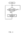
- Fig. 3 is a flowchart showing a control process executed by a transmitter of the theft prevention apparatus according to a first embodiment of the present invention
- Fig. 4 is a flowchart showing a control process for theft prevention that is executed by a controller of the theft prevention apparatus which is equipped in the motorcycle;
- Fig. 5 is a flowchart showing a control process for theft prevention that is executed by the transmitter of the theft prevention apparatus
- Fig. 6 is a plan view of an entire motorcycle according to a second embodiment of the present invention.
- Fig. 7 is a view schematically showing a configuration of main components of the theft prevention apparatus of the motorcycle of Fig. 6;
- Fig. 8 is a flowchart showing a control process for detecting a loss of the transmitter of the theft prevention apparatus equipped in the motorcycle of Fig. 6;
- Fig. 9 is a flowchart showing a control process for detecting the loss of the transmitter of the theft prevention apparatus equipped in the motorcycle of Fig. 6;
- Fig. 10 is a flowchart showing a control process for detecting the loss of the transmitter of the theft prevention apparatus equipped in the motorcycle of Fig. 6;
- Fig. 11 is a flowchart showing a control process for detecting the loss of the transmitter of the theft prevention apparatus equipped in the motorcycle of Fig. 6;
- Fig. 12 is a flowchart showing a control process for detecting the loss of the transmitter of the theft prevention apparatus equipped in the motorcycle of Fig. 6;
- Figs. 13A-13C are views schematically showing a construction of a hand-operated switch forming a part of the theft prevention apparatus of Figs. 6 and 7;
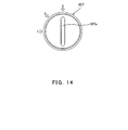
- Fig. 14 is a view schematically showing a construction of a hand-operated switch (dial switch) according to another embodiment
- Fig. 15 is a flowchart showing a control process of a theft prevention apparatus according to the second embodiment
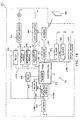
- Fig. 16 is a view schematically showing a configuration of main components of a theft prevention apparatus of a motorcycle according to a third embodiment
- Fig. 17 is a flowchart showing a control process of the theft prevention apparatus of Fig. 16.
- Fig. 18 is a plan view of an entire motorcycle according to the third embodiment.
- a motorcycle 1 is equipped with a theft prevention apparatus according to a first embodiment of the present invention, and a portable (pocketable) transmitter 2 is configured to be remote-controllable.
- the motorcycle 1 includes a receiver 11, a controller 12, a head light 13 also configured to serve as an alarm indicator, a head light drive circuit 14 configured to flash the head light 13 as the alarm indicator, a trip meter 15 configured to display a travel distance of the motorcycle 1, a reset circuit 16 configured to reset the trip meter 15, an antenna 17 connected to the receiver 11 and configured to receive a user identification (ID) code which is transmitted by radio from the transmitter 2, a vehicle transmitter 18 configured to transmit a response signal by radio to the transmitter 2, a battery 19, and a power supply circuit 10 configured to function as a main switch of the motorcycle 1.
- the controller 12 may be an engine control unit (ECU) configured to control an engine and other components of the motorcycle 1, or otherwise may be additionally equipped.
- ECU engine control unit
- the transmitter 2 includes a control unit 21, an antenna 22 connected to the control unit 21, a transmitter receiver 23 configured to receive a response signal from the motorcycle 1 side, a battery 24, and an LED (light emitting diode) light (hereinafter simply referred to as LED) 25 which serves as a self-indicator.
- LED light emitting diode
- the control unit 21 of the transmitter 2 is provided with a transmission circuit configured to transmit the user ID code at appropriate time intervals.
- the control unit 21 is configured to transmit the user ID code by radio from the transmission circuit thereof to the motorcycle 1 side through the antenna 22.
- the time intervals may be set so that the user identification code can be certified without wait time, for example, 0.2 second, or 10 seconds, within a range of 0.1 second to 5 minutes, desirably according to a travel speed of the motorcycle 1.
- the control unit 21 is electrically connected to the battery 24, for example, a button battery, which serves as a power supply in this embodiment.
- the control unit 21 is communicatively coupled to the transmitter receiver 23 through a communication line and is configured to receive a response signal transmitted from the motorcycle 1 side and to determine whether or not the receiver 11 of the motorcycle 1 has received the user ID code.
- the control unit 21 is electrically connected to the LED 25 and is configured to light the LED 25 after detecting that the control unit 21 does not obtain the response signal once or predetermined consecutive times.
- the transmitter 2 is sized to be accommodated in a pocket or the like of shirt or pants to enable the rider to carry the transmitter 2 around.
- a longitudinal length and a lateral length may be approximately 3cm and approximately 2cm, respectively, and a thickness may be approximately 0.5cm.
- the receiver 11 of the motorcycle 1 is communicatively coupled to the transmitter 2 by radio and the controller 12 through a communication line or by radio and is configured to receive the user ID code by radio from the transmitter 2 and to transmit the user ID code to the controller 12.
- the receiver 11 is coupled to the antenna 17 through a communication line.
- the controller 12 determines whether or not the received user ID code matches a user ID code pre-stored in a memory (not shown) contained therein. If it is determined that these two user ID codes match, the controller 12 executes control via a control line to cause the power supply circuit 10 to be turned ON. As a result, an ignition circuit of the engine is turned ON and a starter circuit is turned ON. Now, the engine of the motorcycle 1 is ready to start-up.
- the controller 12 instructs the vehicle transmitter 18 to transmit a response signal to the transmitter 2.
- the vehicle transmitter 18 transmits the response signal by radio to the transmitter 2 through the antenna 17.
- the transmitter 2 receives the response signal through the antenna 22 and the transmitter receiver 23.
- the controller 12 maintains the power supply circuit 10 in OFF-state. Therefore, an ignition circuit of the engine of the motorcycle 2 remains in OFF-state, and the starter circuit remains OFF-state.
- the transmitter 2 may be provided with a transmission button which is configured to be pressed to allow the user ID code to be transmitted by radio. This makes it possible to inhibit wasteful power consumption in the battery 24 of the transmitter 2.
- the motorcycle 1 may be provided with a reception button configured to be pressed for a predetermined time interval to allow power to be supplied from the battery 19 to the controller 12. This makes it possible to inhibit wasteful consumption in the battery 19 equipped in the motorcycle 1.
- an electric wave (including electromagnetic wave) is desirably transmitted from the vehicle transmitter 18 and is received by the transmitter receiver 23 of the transmitter 2 to charge the battery 24 of the transmitter 2.
- the user ID code is transmitted from the transmitter 2 at the appropriate time intervals (see flowchart of Fig. 3).
- the receiver 11 (see Fig. 1) of the motorcycle 1 receives the user ID code and the controller 12 determines whether or not the receiver 11 has received the user ID code (step S1).
- the controller 12 determines whether or not the received user ID code matches the user ID code pre-stored in the memory (step S2), and if these two user ID codes match, the controller 12 transmits a response signal by radio to the transmitter 2 (step S3). Then, the controller 12 resets the number of times "n" the user ID code is not received (step S4).
- step S5 the controller 12 adds one to "n” (step S5). Then, the controller 12 determines whether or not "n” has reached a predetermined number of times "N" (e.g., five) (step S6). If it is determined that "n” is less than "N”, the controller 12 returns the process to step S1. On the other hand, if it is determined that "n” has reached "N”, the controller 12 drives the reset circuit 16 of the trip meter 15 to reset the trip meter 15 (step S7). In addition, the controller 12 determines that the transmitter 2 (see Fig. 1) has fallen off of the pocket or the like of the rider, and turns ON the head light drive circuit 14 (step S8) to light the head light 13.
- N e.g., five
- the head light 13 is configured to flash to be distinguishable from normal lighting, it alternatively may be lighted in other suitable manners to enable the rider to distinguish it from the normal lighting, including flashing of direction indicators or emission of sound of a horn.
- an alarm light equipped on a meter or other position of the motorcycle 1 may be lighted, or otherwise a warning (alarm) sound emitter equipped on the meter or other position of the motorcycle 1 may be turned ON.
- the trip meter 15 may be reset to, rather than "zero", a value obtained by multiplying a time required for counting "n” by the associated travel speed at that point of time (substantially equal to a travel distance from the first detection that the user ID code is not received. Thereby, the trip meter 15 can present a distance from a current point to a vicinity of the point where the transmitter 302 has fallen off. In order to obtain a more precise distance, the reset value may be calculated by integrating speeds by time.
- step S 9 the controller 12 activates a timer (step S 9).
- the controller 12 determines whether or not a count of the timer has reached a predetermined time (step S10). If it is determined that the count has reached the predetermined time, the controller 12 causes the horn to emit a sound to inform the rider that the count has reached the predetermined time (step S11).
- the controller 12 determines whether or not the user ID code has been inputted with another user input device such as an input button provided in the vicinity of the meter or gauge of the motorcycle 1 (step S12). If it is determined that the user ID code has been inputted, the controller 12 turns OFF the head lamp drive circuit 14 and stops operation of the horn (step S13).
- the transmitter 2 transmits the user ID code at the appropriate time intervals (step S100) as described above, and the control unit 21 determines whether or not the transmitter receiver 23 has received the response signal from the motorcycle 18 side (step S101).
- control unit 21 reduces transmission time interval from the appropriate time interval (step S102).
- the control unit 21 adds one to the number of times "m" at which the receiver 23 does not receive the response signal (step S103).
- the control unit 21 determines whether or not "m” has reached predetermined number of times "M” (e.g., five times). If it is determined that "m” is less than “M”, the control unit 21 returns the process to step S100. On the other hand, if it is determined that "m” reached "M”, the control unit 21 lights the LED 25 (step S105).
- the LED 25 may desirably be configured to flash to enable the rider to easily recognize this information. Rather than the LED 25, the transmitter 2 may be provided with a buzzer configured to emit a sound.
- the controller 12 upon detecting that the receiver 11 of the motorcycle 1 does not receive the user ID code during travel of the motorcycle 1, the controller 12 causes the trip meter 15 to be reset, and the head light 13 to flash or the like to enable the rider to recognize this.
- the LED 25 of the transmitter 2 which has fallen off of the pocket or the like flashes.
- the rider is informed of a distance which the rider should travel back.
- the transmitter 2 since the transmitter 2 is flashing, or otherwise the buzzer is emitting a sound at the spot where the transmitter 2 has fallen off and has been lost, the rider can easily find the transmitter 2 even during night.
- the receiver 11 of the motorcycle 1 does not receive the user ID code from the transmitter 2 if the motorcycle 1 has been stolen, the head light 13 flashes and further the horn emits a sound in a relatively short time after stolen. This makes it possible that a third party around there (or policeman) recognizes that stolen motorcycle 1 is a stolen one.
- the theft prevention apparatus of the present invention is, of course, applicable to vehicles equipped with a driver's seat which is open to outside, which are other than the motorcycle, or personal watercraft (PWC). Especially, in the case of the personal watercraft, the theft prevention apparatus of this embodiment also serves as a so-called "tether switch" provided against the rider' s falling off of the watercraft into the water.
- a motorcycle 201 which is one type of leisure vehicles, is equipped with an on-vehicle theft prevention apparatus A shown in Fig. 7, including a receiver (receiver having a vehicle transmitter) 211 of Fig. 7.
- Directional antennae 217 (217R and 217L: see Figs. 6 and 7) are mounted to mounting portions of back mirrors Bm on both sides of a front cowling Fk of the motorcycle 201 of Fig. 6.
- the antennae 217R and 217L are each capable of receiving a radio wave in an angular range of about 15 to 40 degrees, for example, about 30 degrees in this embodiment. More specifically, as shown in Fig. 6, 25 degrees are made between a center axis of the motorcycle 201 and a specific direction which is rearward of the antenna 217R (217L) and near the center axis of the motorcycle 201, and 30 degrees are made rightward and leftward with respect to the specific direction.
- an overlapping region of the receivable angular ranges of the two antennae 217R and 217L is illustrated as being colored. While the overlapping region of the angular ranges of the respective antennae 217R and 217L cover s a rider's seat Rs, they are not intended to be limited to this, but actually may be about 10 to 60 degrees or larger than 60 degrees.
- the antennae 217R and 217L are connected to the receiver 211 equipped in the motorcycle 201 through a signal line L1, and the receiver 211 is connected to a controller 212 through a signal line L2.
- the controller 212 includes a comparator configured to compare two signals received by the receiver 211 through the antennae 217R and 217L to determine whether a difference in intensity between these two signals is zero or less than a predetermined value. If it is determined that the difference in intensity between the two signals is zero or less than the predetermined value, the controller 212 is configured to determine whether or not a received user ID code matches a correct user ID code for certification of the user ID code which will be described later.
- the controller 212 is configured not to execute a process for certifying the user ID code. It shall be appreciated that the receiver 211 may be provided with the comparator.
- the controller 212 contains a memory 212m configured to store the correct user ID code.
- the controller 212 determines whether or not the user ID code transmitted from a transmitter (transmitter with transmitter receiver) 302 carried in the pocket or the like of the rider to the receiver 211 matches the correct user ID code stored in the memory of the controller 212.
- the controller 212 is connected to a flasher 305 of the motorcycle 201 through an electric wire L3, and is configured to answerback by flashing the flasher 305 when the received user ID code matches the correct user ID code.
- the controller 212 is connected to a FI lamp 312 through en electric wire L7. If it is determined that the two ID codes do not match, the controller 212 causes the FI lamp 312 to flash to inform the rider of "mismatch".
- the controller 212 is connected to a battery 219 loaded in the motorcycle 201 through an electric wire L4.
- a hand-operated switch 307 is provided in the electric wire L4 connecting the controller 212 to the batter 219. Only when the hand-operated switch 307 is being operated to an ON-position, the power is supplied from the battery 219 to the controller 212.
- An electric wire L5 is configured to branch from a position of the electric wire L4 between the battery 219 and the hand-operated switch 307 and is connected, through a relay 308, to an FI (fuel and injection system) 309, a meter circuit module (meter system) 310, a lock circuit module (lock system) 311, and a relay 313 through which power is supplied to a starter circuit to drive a starter motor M.
- FI fuel and injection system
- the relay 308 is turned ON and OFF in accordance with an electric signal from the controller 212 and is configured to supply the power from the battery 219 to the FI circuit module 309, the meter circuit module 310, the lock circuit module 311, and the relay 313. More specifically, upon the relay 308 being turned to ON-state, the power is supplied from the battery 219 to the FI circuit module 309, and the meter circuit module 310 to cause these circuits to be turned ON. In addition, the lock circuit module 311 becomes active to unlock a steering lock or a locking device configured to hold a helmet. Further, the relay 313 is turned to ON-state and the starter circuit is turned ON. Under this condition, the engine of the motorcycle 201 is ready to start-up and the motorcycle 201 becomes steerable.
- the electric wire L5 branches and is connected to the controller 212 through the relay 315 to allow the power to be supplied to the controller 212 through the relay 315 after the operation of the hand-operated switch 307 terminates to cause the hand-operated switch 307 to turn to an OFF-position.
- the relay 315 and the controller 212 has a self maintenance function to supply the power to the controller 212.
- the electric wire L5 further branches and is configured to connect, through the relay 313, a starter switch 314, a starter motor M provided downstream of the starter switch 314, and the battery 219.
- the hand-operated switch 307 may be a kill switch including a slidable switch which is disposed in the vicinity of a right grip of a handle bar Hb of the motorcycle shown in Fig. 6. It would be desirable to use a position added to the kill switch configured to stop the engine, since the number of components will not increase. If the rider operates the hand-operated switch 307 with a thumb to cause a slidable lever (movable element) 307a to move counterclockwise from a home position as indicated by a solid line in Fig. 13B to a position as indicated by a solid line in Fig. 13A (corresponding to a two-dotted line in Fig. 13B) against a spring force for keeping the state indicated by the solid line of Fig.
- the power can be supplied to the controller 211 and the receiver 211 while the rider is operating the switch 30 with the thumb.
- the slidable lever 307a returns to the home position by the spring force.
- the kill switch may be replaced by a n existing lap time start/ stop switch provided in the vicinity of a right end of the handle bar.
- the kill switch which is the hand-operated switch 307, may be configured to be operated by the thumb of the rider to cause the slidable lever 307a to slide from the home position indicated by the solid line in Fig. 13B to a position indicated by a solid line in Fig. 13C, thereby turning the kill switch to an ON-position to stop the engine.
- the kill switch may be configured to be operated by the thumb of the rider to cause the slidable lever 307a to slide from the position indicated by the solid line in Fig. 13C to the home position indicated by the solid line in Fig. 13B, thereby returning the kill switch to an OFF-position. With the slidable lever 307a in the position indicated by the solid line in Fig. 13B, the engine in the stopped state can start-up.
- the slidable lever 307a has a detent function to keep the positions indicated by the solid lines of Fig. 13B and 13C, unless it is intentionally moved to another position by the thumb or the like of the rider.
- the engine can re-start up by returning the slidable lever 307a to the home position indicated by the solid line in Fig. 13B within a predetermined time, for example 10 minutes required for fueling.
- a predetermined time for example 10 minutes required for fueling.
- the theft prevention apparatus is functioning, and therefore, the engine cannot re-start up unless the user ID code has been certified.
- the controller 212 is connected through an electric wire L6 to a display device 318 installed on a meter panel. If the battery of the transmitter 302 of the theft prevention apparatus is running short of power, this information is transmitted from the transmitter 302 to the receiver 211.
- the receiver 211 (or the controller 212) causes the display device 318 to display information indicating that the battery of the transmitter 302 is running short of power, to be presented to the rider. According to this information, the rider replaces the battery of the transmitter 302.
- a dial switch 307 may be independently provided, including a movable portion 307a capable of being set in a position selected from plural positions (e.g., three positions in the second embodiment in Fig. 14), or otherwise, a switch having another configuration may be provided, although not shown.
- a switch having another configuration may be provided, although not shown.
- one-dotted line connecting the blocks indicate signal lines and solid lines indicate the electric wires.
- the theft prevention apparatus configured as described above functions as described below.
- a control process executed by the controller 212 and the associated theft prevention function will be described with reference to the flowchart of Fig. 15.
- step S401 the rider rides on the rider's seat Rs of the motorcycle 201 and operates the hand-operated switch 307 with the transmitter 302 put in the pocket or the like.
- the user ID code transmitted from the transmitter 302 is received by the antennae 217 (217R and 217L) (step S402).
- the received user ID code is transmitted to the controller 212 through the receiver 211.
- the controller 212 compares intensity between the received signals from the antenna 217R and 217L (step S403). When the rider is riding on the rider's seat Rs as described above, the difference in the intensity is zero or less than the predetermined value.
- the controller 212 determines whether or not the received user ID code matches the correct user ID code stored in the memory 22m (step S404). On the other hand, if it is determined that the difference is not less than the predetermined value, the controller 212 returns the process to step S401.
- step S404 the controller 212 flashes the flasher 305 of the motorcycle 201 to inform the rider of the match between the two ID codes (step S405), and advances the process to step S407.
- step S406 the controller 212 flashes the FI lamp 312 to inform the rider of the mismatch.
- the controller 212 turns ON the relay 308 to turn each of the FI circuit module 309 and the meter circuit module 310 to an ON-state (active state), and turns ON the relay 313 (step S407).
- the controller 212 turns the lock circuit module 311 to an ON-state (active state) to unlock the steering lock or the holding device of the helmet.
- the controller 212 turns ON the relay 315 to enable the power to continue to be supplied to the controller 212. Then, the controller 212 activates a timer configured by software (program) (step S408).
- step S409 If the rider turn the starter switch 314 of the engine to an ON-position within a predetermined time, for example, five minutes (step S409), the starter motor M rotates while the starter switch 314 is in the ON-position, causing the engine to start-up (step S410). So, the control process for the theft prevention terminates.
- the controller 212 if the predetermined time (five minutes) has elapsed with the starter switch 314 unoperated, the controller 212 returns the process to an initial state (START in Fig. 5). In other words, after an elapse of the predetermined time, the engine cannot start-up unless the steps for certifying the user ID code have been done.
- the controller 212 determines whether or not the engine has started-up as indicated by a solid line of a flowchart in Fig. 8. If it is determined that the engine has started-up, the receiver 211 transmits a user ID code transmission request signal to the transmitter 302 at appropriate time intervals.
- the transmitter 302 transmits the user ID code by radio.
- the transmitted user ID code is received by the receiver 211 (see Fig. 7) of the motorcycle 201.
- the controller 212 adds one to "n" (step S205). Then, the controller 212 determines whether or not "n" has reached a predetermined number of times "N" (e.g., five times) (step S206). If it is determined that "n” is less than "N”, the controller 212 returns the process to step S201. On the other hand, if it is determined that "n” has reached “N”, the controller 212 drives the reset circuit of the trip meter within the meter circuit module 310 to reset the trip meter (step S207).
- N e.g., five times
- the controller 212 further determines that the transmitter 302 has fallen off of the pocket or the like of the rider, and turns ON the flasher 305 (step S208) to flash the flasher 305.
- the flasher 305 is not intended to be limiting, but other suitable alarm indicators, including the head light, the horn, etc, may be employed.
- the alarm indicator may be an alarm light mounted to the meter or other position of the motorcycle 201, or an alarm sound emitter mounted to other position of the motorcycle 201.
- the controller 212 determines whether or not the motorcycle 201 has started traveling. If it is determined that the motorcycle 201 has started traveling, the receiver 211 transmits a user ID code transmission request signal to the transmitter 302 at appropriate distance intervals, for example, every 500 meters.
- the transmitter 302 transmits the user ID code by radio.
- the controller 212 determines whether or not the engine has started-up based on detected data from an engine tachometer or the like, and determines whether or not the motorcycle 201 has started traveling, based on detected data from a speed meter or the like. It will be appreciated that global positioning system (GPS) may be employed to detect that the motorcycle 201 has started traveling.
- GPS global positioning system
- the user ID code transmitted from the transmitter 302 is received by the receiver 211 (see Fig. 7) of the motorcycle 201.
- the controller 212 determines whether or not the receiver 211 has received the user ID code (step S301). Then, the controller 212 determines whether or not the received user ID code matches the user ID code stored in the memory (step S302). If it is determined that these two codes match, the controller 211 transmits a response signal by radio to the transmitter 302 (step S303). Then, the controller 211 resets "n" to zero (step S304), and resets a transmission timing of the user ID code to an initial (normal) timing (step S320).
- the controller 212 adds one to "n" and reduces the appropriate distance interval by a predetermined value, for example, 50%, or otherwise according to a traveling speed at that point of time (step S305). Then, the controller 212 determines whether or not "n" has reached "N" (step S306).
- step S306 If it is determined that "n” is less than “N” in step S306, the controller 212 returns the process to step S301. On the other hand, if it is determined that "n” has reached “N”, the controller 212 drives the trip meter reset circuit of the meter circuit module 310 to reset the trip meter (step S307). In addition, the controller 212 determines that the transmitter 302 (see Fig. 7) has fallen off of the pocket or the like, and turns ON the flasher 305 which is the alarm indicator of the second embodiment, to light the flasher 305.
- the alarm indicator may be other suitable devices as described previously. Instead of the trip meter, a time counting device, for example, a timer may be configured to specify an elapse of time after the transmitter 302 has been lost.
- the trip meter 15 of the meter circuit module 310 may be reset to, rather than "zero", a value obtained by multiplying a time required for counting "n” by the associated traveling speed at that point of time (substantially equal to a traveling distance from the first detection that the user ID code is not received). Thereby, the trip meter can accurately present a distance from a current point to a vicinity of the point where the transmitter 302 has been lost. In order to obtain a more accurate distance, the reset value may be calculated by integrating speeds by time.
- step S 9 the controller 12 activates a timer (step S 9).
- the controller 12 determines whether or not a count of the timer becomes a predetermined time (step S310). If it is determined that the count becomes the predetermined time, the controller 212 causes the horn to emit a sound to inform the rider of this (step S311).
- the controller 212 determines whether or not the user ID code has been inputted with another user input device such as an input button provided in the vicinity of the meter of the motorcycle 1 (step S312). If it is determined that the user ID code has been inputted with the user input device, the controller 212 turns OFF the flasher 305 and stops activation of the horn (step S313).
- the transmitter 302 transmits the user ID code in response to the user ID code transmission request signal (step S350), and a control (not shown) unit of the transmitter 302 determines whether or not the transmitter 302 has received the response signal from the vehicle receiver 211 within a predetermined time (step S351).
- step S352 If it is determined that the transmitter 302 does not receive the response signal in step S351, the control unit of the transmitter 302 adds one to "m" (step S352).
- the control unit of the transmitter 302 determines whether or not "m” has reached a predetermined number of times M (e.g., five times) (step S353). If it is determined that "m” is less than "M”, the control unit returns the control process to step S350. On the other hand, if it is determined that "m” has reached "M”, the control unit executes control to light the LED of the transmitter 302 (step S354).
- the LED may desirably be flashed so as to be easily identified by the rider. Rather than the LED, the transmitter 302 may be provided with a buzzer configured to emit a sound.
- the trip meter upon detecting that the receiver 211 of the motorcycle 201 does not receive the user ID code during travel of the vehicle, the trip meter is reset and the flasher 305 flashes to enable the rider to recognize this information.
- the LED of the transmitter 302 which has fallen off of the pocket or the like of the rider is flashing. So, the rider is informed of a distance which the rider should travel back.
- the transmitter 302 since the transmitter 302 is flashing, or otherwise the buzzer is emitting a sound at the spot where the transmitter 302 has fallen and has been lost, the rider can easily find the transmitter 302 even during night.
- the effects of the first embodiment are also obtained.
- the controller 212 turns ON the relay 308 and the relay 315 for a predetermined time required for fueling or the like, for example, 10 minutes, and maintains this state.
- a predetermined time for example, 10 minutes, and maintains this state.
- the process for certifying the user ID code between the transmitter 302 and the controller 212 via the receiver 211 is carried out repeatedly at appropriate time intervals. If the rider is riding on the rider's seat Rs, the process transitions from step S403 to step S404 in the flowchart of Fig. 15, and thereby the engine can start-up.
- step S403 the process transitions from step S403 to step S401 rather than step S404.
- the theft prevention function is active. As a result, the motorcycle 201 will not be stolen while the rider is going to somewhere else.
- the power is not substantially consumed on the motorcycle 201 side before the hand-operated switch 307 is operated.
- wasteful power consumption is inhibited.
- the process for certifying the user ID code is carried out only when the rider is positioned in a predetermined location, for example, the rider's seat Rs, whereas the process for certifying user ID code is not executed when the rider is positioned in a different location, for example, laterally of the motorcycle 201.
- theft prevention function is enhanced.
- the engine control unit (ECU) of the motorcycle 201 may function as the controller 212 of the second embodiment. Nonetheless, the ECU is desirably employed as the controller 212, without an increase in the number of components and an increase in a manufacturing cost.
- a theft prevention apparatus of a leisure vehicle according to a third embodiment will be described with reference to Figs. 16 through 18.
- an on-vehicle theft prevention apparatus A2 is mounted in a motorcycle 501 (see Fig. 18), including a receiver 511.
- the on-vehicle theft prevention apparatus A2 has an antenna 517 for transmission and reception, which is provided in a position of the motorcycle 501, for example, under the rider's seat Rs.
- the antenna 517 is configured to receive a signal from all directions and to transmit a signal to all directions.
- the antenna 517 is, as shown in Fig. 16, connected, through a signal line L101, to the receiver 511, which is in turn connected to a controller 512 through a signal line L102.
- the controller 512 includes a built-in memory 512m configured to store a correct user ID code. The controller 512 determines whether or not a user ID code transmitted from a portable transmitter 502 being carried in the pocket or the like of the rider and received by the receiver 511 matches the correct user ID code stored in the memory 512m.
- the controller 512 is connected to a flasher 605 of the motorcycle 201 through an electric wire L103. If it is determined that the user ID code transmitted from a portable transmitter 502 matches the correct user ID code, the controller 512 answerbacks by flashing the flasher 605.
- the controller 512 is connected to an FI lamp 612 through an electric wire L107, and is configured to selectively flash the FI lamp 612 if the two ID codes do not match, to inform the rider of the mismatch between the two codes.
- the controller 512 is connected to a lock circuit module (lock system) 611 and a lock actuator 617 through an electric wire L111.
- a control operation of the controller 512 and an operation control of the lock circuit module 611 enable power to be supplied to the lock actuator 617, which thereby is activated.
- the lock actuator 617 is not intended to be limited to a lock actuator configured to lock and unlock a steering lock, but may be a lock actuator configured to lock and unlock a helmet lock or a seat lock, a lock actuator configured to lock and unlock a fuel cap, or otherwise an actuator configured to lock and unlock a saddle bag.
- the controller 512 is connected to a battery 519 loaded in the motorcycle 501 through an electric wire L104.
- a hand-operated switch 607 is provided in a position of the electric wire L104.
- the controller 512 is configured to turn ON a relay 615 and a relay 608, upon the hand-operated switch 607 being turned to an ON-position.
- the controller 512 is directly connected to the battery 519 side through an electric wire L104s indicated by a broken line, and is configured to be supplied with a minute current (minute power) from the battery 519 before the hand-operated switch 607 is turned to an ON-position.
- the supplied minute current enables the controller 512 to move to and keep a "sleep mode" (standby state).
- the relay 615 Upon the hand-operated switch 607 being operated, the relay 615 is turned ON. Thereby, an electric wire L105 which branches from a position between the hand-operated switch 607 and the battery 519 is connected to the controller 512 through the relay 615, thereby allowing the power to be supplied from the battery 519 to the controller 512. Thereby, with the hand-operated switch 607 being in an OFF-position after the operation of the hand-operated switch 607 terminates, the power is supplied to the controller 512. That is, the relay 615 and the controller 512 have a self maintenance function to supply the power to the controller 512.
- the relay 608 is turned ON in accordance with a control signal from the controller 512.
- the electric wire L105 is connected to the FI circuit module (ignition and fuel system) 609 and the meter circuit module (meter system) 610 through the relay 608, thereby allowing the power to be supplied from the battery 519 to the FI circuit module (ignition and fuel system) 609 and the meter circuit module (meter system) 610.
- the electric wire L105 is connected, through a relay 613, to a starter circuit (starter system) including a starter motor M and a starter switch 614, which are turned to an ON-state upon the relay 613 being turned ON.
- the relay 608 is turned ON and OFF in accordance with a control signal from the controller 512, and is configured to supply the power from the battery 519 to the FI circuit 609, and to the meter circuit 610.
- the relay 613 is turned ON and OFF in accordance with the control signal from the controller 512, and is configured to supply the power from the battery 519 to the starter switch 614 and the starter motor M.
- Each of the lock circuit module 611, the FI circuit module 609, and the meter circuit module 610 includes a CPU containing a built-in memory configured to store a correct user ID code therein.
- Each of the circuits 611, 609, and 610, to be precise, the CPU included therein, is configured to execute a process for certifying the user ID code.
- the lock circuit module 611, the FI circuit module 609, and the meter circuit module 610 are coupled to the controller 512 through a CAN (controller area network), and are configured to receive the received user ID code from the controller 512.
- CAN controller area network
- the hand-operated switch 607 is a start/ stop switch including a push button switch which is provided in the vicinity of a right grip of a handle bar Hb of the motorcycle 501 of Fig. 18 and which is configured exclusively for the theft prevention apparatus.
- an existing "lap time start/ stop switch" provided in the vicinity of the right grip of the handle bar Hb may be employed, or otherwise one position may be added to the kill switch and shifting to the position may be performed against a spring force.
- the hand-operated switch 607 may be a dial switch 307 including a movable portion 307a capable of selecting a position from plural positions (three positions 1, 2, and 3 in the embodiment of Fig. 14), or other switch having another configuration, although not shown.
- the start/stop switch which is one type of the hand-operated switch 607, is configured to start-up and stop the engine by a short-time (about one second) operation and a long-time (about two to three seconds) operation. More specifically, by the short-time operation, a control for starting-up the engine starts, whereas by the long-time operation, a control for stopping the engine is executed.
- the controller 5142 is connected to a display device 618 installed on, for example, a meter panel, through an electric wire L106. If the battery of the transmitter 502 of the theft prevention apparatus is running short of power, the transmitter 502 transmits this information to the receiver 511. Upon the receiver 511 receiving the signal, the controller 512 causes the display device 618 to display a warning indicating that "the battery of the transmitter 502 is running short of power", to be presented to the rider. According to the warning, the rider replaces the battery.
- one-dotted lines connecting the respective block components indicate signal lines, solid lines indicate power lines, and broken lines indicate power lines through which the minute current is supplied.
- the on-vehicle theft prevention apparatus A2 transmits, to the transmitter 502, a request signal for requesting the transmitter 502 to transmit a predetermined transmitter detection signal.
- the transmitter 502 receives the request signal, the transmitter 502 transitions from a sleep mode to an active mode, and transmits the transmitter detection signal to the on-vehicle apparatus A2.
- the transmitter 502 is configured to consume only a minute power for receiving the request signal.
- the above mentioned theft prevention apparatus performs or disenables a theft prevention function as described below in detail.
- the control process or the like executed by the controller 512 and the associated theft prevention function will be described with reference to a flowchart of Fig. 17.
- step S501 When the rider, carrying the transmitter 502 in the pocket, operates the hand-operated switch (start/ stop switch) 607 of the motorcycle 501 for a short time (about one second) within a predetermined distance over which the transmitter 502 and the receiver 511 can communicate each other) (step S501), the controller 512 transitions from the sleep mode to the active mode.
- the controller 512 causes the relay 615 to be turned ON so that the power continues to be supplied from the battery 519 to the controller 512 (step S502).
- the controller 512 transmits a request signal to the transmitter 502 through the receiver 511 and the antenna 517 to request the transmitter 502 to transmit the potable device detection signal (step S503).
- a control unit (not shown) of the transmitter 502 transitions from the sleep mode (standby state) during which only a minute power is consumed, to the active state, and determines whether or not the request signal matches a predetermined signal. If it is determined that the two signals match, the transmitter 502 transmits the transmitter detection signal to the controller 512 side. On the other hand, if it is determined that the two signals do not match, the control unit of the transmitter 502 does not transmit the transmitter detection signal to the controller 512 side. So, the controller 512 determines whether or not it has received the transmitter detection signal within a predetermined time after the controller 512 has transmitted the request signal (step S504).
- the FI lamp 612 is configured not to flash and the display device 618 is configured not to display any information to inhibit any mischievous attempt to operate the hand-operated switch 607 by a third party, which will cause the FI lamp 612 to flash or the display device 618 to display some information.
- the controller 512 determines whether or not the detection signal is associated with a first transmitter of transmitters 502 belonging to one group, based on a signal code contained in the transmitter detection signal (step S506). If it is determined that the signal code matches a predetermined signal code of the first transmitter 502, the controller 512 transmits a user ID code transmission request signal to the transmitter 502 to request the transmitter 502 to transmit the user ID code (step S507).
- the controller 512 determines whether or not the signal code matches a predetermined code of a second transmitter 502 belonging the group (step S508), and then determines whether or not the signal code matches a predetermined code of a third transmitter belonging to the group if it is determined that the signal code does not match the predetermined code of the second transmitter 502 (step S509). In this manner, the controller 512 executes a determination process until detecting a match between the signal code and the transmitter 502.
- the controller 512 executes the determination process five times at maximum, although the controller 512 executes the determination process three times in the embodiment of Fig. 17.
- This configuration is intended for one family' use so that five persons can share the motorcycle 201.
- the number of times of the transmitters 502 belonging to the group may be more than or less than five.
- the controller 512 detects whether or not the key with transponder containing the predetermined code has been inserted into the key switch provided on the panel or the like of the motorcycle 501 (step S531). If the key is detected as being uninserted, the controller 512 terminates the control process for disenabling the theft prevention function.
- step S507 the controller 512 advances the process to step S507.
- the transmitter 502 transmits the user ID code to the controller 512 side.
- the controller 512 receives the user ID code through the receiver 511 of the motorcycle 501 (step S510).
- the controller 512 calls the correct user ID code stored in the memory 512m (step S511), and determines whether or not the received user ID code matches the correct user ID code (step S512). If it is determined that these two codes match, the controller 512 turns ON an electric circuit configured to supply power to the lock circuit module 611 and outputs a unlock request signal for executing an unlock process to the lock circuit module 611 via the CAN (step S513), and awaits a user ID code transmission request signal from the lock circuit module 611 to request the controller 512 to output the received user ID code from the transmitter 502 (step S514).
- the lock circuit module 611 receives the unlock request signal, the lock circuit module 611 outputs the user ID code transmission request signal to the controller 512 via the CAN. Receiving the request signal, the controller 512 outputs the received user ID code to the lock circuit module 611 (step S515).
- step S512 if it is determined that the two codes do not match in step S512, the key with transponder containing the predetermined code has been inserted into the key switch (step S532). If the key is detected as being uninserted, the controller 512 causes the FI lamp 612 to flash to inform the rider that the key is uninserted, and causes the display device 618 to display this information in the form of characters or graphic symbols (step S533). Thereby, the control process terminates.
- the lock circuit module 611 is configured to execute the process for certifying the user ID code utilizing the CAN to prevent the motorcycle 501 from being stolen by changing a board (control board) of the controller 512.
- step S533 the FI lamp 612 flashes and the display device 618 displays some information for the sake of the rider's convenience, since any mischievous attempt to operate the hand-operated switch 607 by a third party will not be made, once the controller 512 has certified the user ID code.
- the CPU of the lock circuit module 611 determines whether or not the received user ID code matches the correct user ID code stored in the memory of the CPU. If it is determined that these two codes match, the electric circuit of the lock circuit module 611 is turned ON, thereby causing the motorcycle 501 to move to an unlocking-ON mode.
- the motorcycle 501 does not move to the unlocking-ON mode unless the key with transponder is inserted into the key switch. In other words, an unlocking-OFF mode is maintained.
- the lock circuit module 611 transmits a signal indicating "unlocking-ON” or "unlocking-OFF” to the controller 512, and thus, the control process for unlocking terminates.
- the controller 512 determines whether the received signal from the lock circuit module 611 is "unlocking-ON” or "unlocking-OFF” (step S516). If it is determined that the received signal is "unlocking-ON”, the controller 512 causes the display device 618 to display this information (step S517). In the unlocking-ON mode, the power is supplied from the battery 519 to the lock circuit module 611 through the relay 615 and the controller 512. Thereby, an actuator 617 activates, thereby unlocking the steering lock, the helmet lock, or the seat lock. In this case, in the third embodiment, since the power which is supplied to the lock actuator 617 is not so large, it is supplied to the lock circuit module 617 through the controller 512.
- step S5 the controller 512 detects whether or no the key with transponder has been inserted into the key switch (step S534). If the key is detected as being uninserted, the controller 612 causes the FI lamp 612 to flash and the display device 618 to display this information (step S535), and thus the control process for disenabling the theft prevention function of the theft prevention apparatus terminates. In this case, the theft prevention function is maintained.
- step S534 If the key is detected as being inserted into the key switch in step S534, the controller 512 advances the process to step S517.
- the display device 618 displays the information regarding "unlocking-ON” or "unlocking-OFF” in step S535 to present the rider of this information, since the display of the information on the display device 618 does not result from mischievous attempt by a third party, once the controller 512 has certified the user ID code.
- the lock circuit module 611 activates a built-in timer from the time point when the lock circuit module 611 has moved to the unlocking-ON mode.
- the controller 512 determines whether or not second "short-time operation" to be described later has been performed or the signal from the transmitter 502 has been received (steps S518), and if it is determined that, the process does not advance to a next step, i.e., the signal from the transmitter 502 has not been received and the "short-time operation" has not been performed, within a predetermined time, for example, 10 minutes, the controller 512 causes the lock circuit module 611 to an unlocking-OFF state (step S519) to cause the steering lock, the seat lock, or the like to turn to an ON-state, thereby enabling the theft prevention function to prevent theft of the motorcycle 501.
- the control process for unlocking which is associated with the lock circuit module 611 and the controller 512 terminates.
- step S520 the controller 512 turn ON the relay 608 (step S520), and the power is supplied to the meter circuit module 610 and the FI circuit module 609 (step S521).
- the meter circuit module 610 being supplied with the power, outputs, via the CAN, a user ID code transmission request signal to the controller 512 to request the controller 512 to output the user ID code. Receiving the request signal, the controller 512 outputs the user ID code to the meter circuit module 610 (step S522).
- the controller 512 determines whether or not it has received the user ID code transmission request signal from the meter circuit module 610 within a predetermined time (about 30 seconds) (step S523). If it not determined that it does not receive the request signal, the controller 512 causes the FI lamp 612 to flash to inform the rider of this, or causes the display device 618 to display this information in the form of characters or graphic symbols to be presented to the rider (step S536). Thereby, the control process for the meter circuit module 610 terminates, and hence the meter circuit module 610 maintains inactive. As a result, the theft prevention function is maintained. On the other hand, if it is determined that it has received the request signal, the controller 512 outputs the user ID code to the meter circuit module 610 via the CAN (step S524).
- the meter circuit module 610 is configured to execute the process for certifying the user ID code utilizing the CAN to prevent the motorcycle 501 from being stolen by changing boards of the controller 512 and the lock circuit module 611.
- step S536 the FI lamp 612 flashes and the display device 618 displays some information to inform the rider that the user ID code transmission request signal is not transmitted from the meter circuit module 610, since the flash of the FI lamp 612 or the display of the information on the display device 618 does not result from mischievous attempt by a third party, once the controller 512 has certified the user ID code.
- the CPU of the meter circuit module 610 determines whether or not the received user ID code matches the correct user ID code stored in the memory of the CPU included in the meter circuit module 610. If it is determined that these two user ID codes match, the meter circuit module 610 is turned to an ON-state (active state). In the third embodiment, when the meter circuit module 610 moves to the ON-state (active state), meters or gauges moves to an active state, and head lamps or the like also move to an active state.
- the meter circuit module 610 maintains a OFF-state (inactive state) unless the key with transponder is inserted into the key switch. In this state, the meters or gauges of the motorcycle 501 maintains the inactive state, and thus the theft prevention function is active.
- the meter circuit module 610 transmits a signal indicating "match” or "mismatch” to the controller 512.
- the controller 512 receives the signal indicating "match” or “mismatch” from the mater circuit 610 and detects whether the received signal is “match” or “mismatch” (step S525). If the received signal is detected as being “match”, the controller 512 causes the display device 618 to display this information (step S526).
- the controller 512 detects whether or not the key with transponder has been inserted into the key switch (step S537). If the key is detected as being uninserted, the controller 512 causes the FI lamp 612 to flash and the display device 618 to display this information (step S538). Thus, the control process for the meter circuit module 610 terminates, and the meter circuit module 610 maintains an inactive state. As a result, the theft prevention function is maintained.
- the key is detected as being inserted into the key switch in step S537, the controller 512 advances the process to step S526.
- the controller 512 moves to a standby mode to await a user ID code transmission request signal from the FI circuit module 609 to request the controller 512 to output the user ID code.
- the FI circuit module 609 outputs a user ID transmission request signal to the controller 512 via the CAN.
- the controller 512 receives the request signal, the controller 512 outputs the user ID code to the FI circuit module 609 via the CAN (step S527).
- the controller 512 causes the FI lamp 612 to flash to inform the user that the request signal is not transmitted, and causes the display device 618 to display this information in the form of characters or graphic symbols to be presented to the rider (step S528).
- the FI circuit module 609 is configured to execute the process for certifying the user ID code utilizing the CAN to prevent the motorcycle 501 from being stolen by changing the controller 512, the lock circuit module 611 and the meter circuit module 610.
- step S528 the FI lamp 612 flashes and the display device 618 displays some information to inform the rider that the user ID code transmission request signal is not transmitted from the FI circuit module 609, since the flash of the FI lamp 612 or the display of the information on the display device 618 does not result from mischievous attempt by a third party, once the controller 512 has certified the user ID code.
- the CPU of the FI circuit module 609 determines whether or not the received user ID code matches the correct user ID code stored in the memory of the CPU included in the flash circuit 609. If it is determined that these two codes match, the controller 512 turns the FI circuit module 609 to an ON-state (active state). Thereby, the fuel supply system of the engine becomes active and the ignition system of the engine becomes active.
- the FI circuit module 609 maintains an OFF-state (inactive state) unless the key with transponder is inserted into the key switch. So, no fuel is supplied to the engine and the ignition system and the start-up system maintain an OFF-state. Under this condition, the engine of the motorcycle 501 cannot start-up, and thus the theft prevention function is active.
- the FI circuit module 609 outputs a signal indicating "match” or “mismatch” to the controller 512.
- the controller 512 receives the signal indicating "match” or “mismatch” from the FI circuit module 609, the controller 512 detects whether the received signal is "match” or “mismatch” (step S529). If the received signal is detected as being “match”, the controller 512 causes the display device 618 to display this information, and causes the relay 613 to be turned ON (step S541). Thereby, the start-up system of the engine moves to an ON-mode.
- the controller 512 causes the flasher 605 to flash to inform the rider that all the theft prevention functions equipped in the motorcycle 501 have been disenabled (step S542). Thus, the control process for the theft prevention function terminates.
- the flashing of the flasher 605 which is an answerback, informs the rider that the motorcycle 501 is now ready to start-up of the engine and is steerable.
- step S529 the controller 512 detects whether or not the key with transponder has been inserted into the key switch (step S539). If the key is detected as being uninserted, the controller 512 causes the FI lamp 512 to flash, and causes the display device 618 to display this information (step S540). Thus, the control process for the FI circuit module 609 terminates, and the FI circuit module 609 maintains an inactive state. As a result, the theft prevention function is maintained. If the key is detected as being inserted into the key switch, the controller 512 advances the process to step S541.
- the controller 512 is configured to advance the process to a subsequent step, if the key with transponder is detected as being inserted into the key switch of the motorcycle 501 and if the ID code stored in the transponder matches the correct ID code, even when it is determined that the signal code of the transmitter detection signal is not the predetermined code, or it is determined that the received user ID code does not match the correct user ID code. This will be explained with reference to a flowchart indicated by a broken line of Fig. 17.
- the rider in cases where the rider has the key with transponder without carrying the transmitter 502, the rider can ride the motorcycle 501 having the above-mentioned theft prevention function.
- the user may carry the transmitter 502 in a pocket or a bag, or otherwise, insert the key with transponder into the key switch.
- step for certifying the user ID code is carried out in the meter circuit module 610 and then in the FI circuit module 609, they may be carried out in a reverse order, or otherwise at the same time.
- the step for certifying the user ID code may be performed in components configured to be controlled for theft prevention, which are other than the lock circuit module 611, the meter circuit module 610, and the FI circuit module 609, including a car navigation system, an audio system, etc. In those cases, the theft prevention function is further enhanced.
- a control process for cases where the transmitter 502 has been lost is executed as in the second embodiment, and will not be further described.
- the theft prevention apparatus is configured such that, when the engine is starting-up after the above mentioned steps or before the engine starts-up, the rider operates the hand-operated switch 607 for a long time to stop the engine, or otherwise to cancel a control operation being executed to enable the engine to start-up, thus returning to an initial state.
- the controller 512 executes the determination process in the steps S502 to S505 to determine whether or not the rider carries the predetermined transmitter 502, and causes the display device 618, the FI lamp 612 and the like, to warn the rider that, if the rider should try to stop the engine without carrying the transmitter 502, the engine could not re-start up.
- the hand-operated switch 607 is re-operated for a long time, the relays 607 and 615 are turned OFF, and the FI circuit module 609, the meter circuit module 610, and the lock circuit module 611 turn to OFF-states.
- the relay 613 is turned OFF.
- the lock circuit module 611, the meter circuit module 610, and the FI circuit module 609, as well as the controller 512 are configured to perform the step for certifying the user ID code, the theft of the motorcycle 501 is effectively prevented. Any theft attempt will be unsuccessful unless all of these circuits have been changed. Thus, the theft prevention function is enhanced.
- the rider can start-up the engine easily with the transmitter 502 put in the pocket. Furthermore, the stop of the engine can be effectively inhibited if the transmitter 502 is lost.
- the theft prevention apparatus of the third embodiment since only minimum power is necessary to keep "sleep mode" of the controller 512 before the hand-operated switch 607 is operated, and hence the power is not substantially consumed on the motorcycle 501 side, wasteful power consumption is inhibited.
- the transmitter 502 of the theft prevention apparatus since the transmitter 502 of the theft prevention apparatus also maintains the sleep mode and consumes minute power before the on-vehicle apparatus A2 transmits a request signal for transmitting the transmitter detection signal to the transmitter 502, wasteful power consumption is inhibited.
- the engine control unit (ECU) of the motorcycle 501, or otherwise, another controller may function as the controller 512 of the third embodiment. Nonetheless, the ECU is desirably employed as the controller 512, without an increase in the number of components and an increase in a manufacturing cost.
- the hand-operated switch 607 may be other suitable switches, for example, a pull-in switch or the like positioned around a meter or gauge in the vicinity of the steering head of the handle.
- the present invention is applicable to leisure vehicles such as motorcycles, all terrain vehicles, or personal watercraft (PWC) which are equipped with rider's seats which is open to outside.
- leisure vehicles such as motorcycles, all terrain vehicles, or personal watercraft (PWC) which are equipped with rider's seats which is open to outside.
- PWC personal watercraft
- a security device for a vehicle having a non-enclosed driver/rider seat and/or steering control interface comprising portable transmission means to be carried by the driver/rider and operable to transmit a user identification code at predetermined intervals when the vehicle is in use and means to be fitted on the vehicle for receiving the user identification code transmitted by said portable transmission means and issuing a warning to the driver/rider if, during use of the vehicle, a said user identification code is not received within a predetermined interval.
- a security device for a vehicle having a non-enclosed driver/ rider seat and/or steering control interface comprising a device to be fitted to the vehicle for issuing transmission requests to a portable transmission means to be carried by the driver/rider receiving a said transmission request and transmitting a reply in response to said transmission request, said device being arranged to issue said transmission requests at predetermined intervals during use of the vehicle and issuing a warning to the driver that the portable transmission means may be lost if the portable transmission means does not transmit a reply to a transmission request within a predetermined time.
Landscapes
- Engineering & Computer Science (AREA)
- Mechanical Engineering (AREA)
- Lock And Its Accessories (AREA)
- Emergency Alarm Devices (AREA)
Applications Claiming Priority (4)
| Application Number | Priority Date | Filing Date | Title |
|---|---|---|---|
| JP2004129907 | 2004-04-26 | ||
| JP2004129907 | 2004-04-26 | ||
| JP2005109998A JP4481207B2 (ja) | 2004-04-26 | 2005-04-06 | レジャービィークルの盗難防止装置 |
| JP2005109998 | 2005-04-06 |
Publications (2)
| Publication Number | Publication Date |
|---|---|
| EP1591329A1 true EP1591329A1 (fr) | 2005-11-02 |
| EP1591329B1 EP1591329B1 (fr) | 2015-04-08 |
Family
ID=34941035
Family Applications (1)
| Application Number | Title | Priority Date | Filing Date |
|---|---|---|---|
| EP20050252595 Active EP1591329B1 (fr) | 2004-04-26 | 2005-04-26 | Dispositif d'antivol pour véhicules de loisir |
Country Status (3)
| Country | Link |
|---|---|
| US (1) | US7656278B2 (fr) |
| EP (1) | EP1591329B1 (fr) |
| JP (1) | JP4481207B2 (fr) |
Cited By (8)
| Publication number | Priority date | Publication date | Assignee | Title |
|---|---|---|---|---|
| EP1690761A3 (fr) * | 2005-01-21 | 2006-11-02 | Kawasaki Jukogyo Kabushiki Kaisha | Système préventif anti-vol d'un véhicule de loisir |
| EP1886885A2 (fr) * | 2006-08-01 | 2008-02-13 | Yamaha Hatsudoki Kabushiki Kaisha | Appareil de contrôle de véhicule et véhicule équipé avec celui-ci |
| ITMO20120147A1 (it) * | 2012-06-01 | 2013-12-02 | Meta System Spa | Batteria per veicoli elettrici |
| CN105966347A (zh) * | 2016-06-21 | 2016-09-28 | 广西科技大学 | 一种电动车防盗系统 |
| CN106080509A (zh) * | 2016-06-21 | 2016-11-09 | 广西科技大学 | 一种电动车防盗系统控制方法 |
| EP3127792A3 (fr) * | 2015-07-09 | 2017-03-08 | Yamaha Hatsudoki Kabushiki Kaisha | Système d'authentification de véhicule monté à califourchon et un tel véhicule |
| EP3115284A3 (fr) * | 2015-07-09 | 2017-03-08 | Yamaha Hatsudoki Kabushiki Kaisha | Système d'authentification de véhicule à califourchon et un tel véhicule |
| CN106627860A (zh) * | 2016-10-12 | 2017-05-10 | 南京理工大学 | 电动自行车电池防盗报警系统及报警方法 |
Families Citing this family (33)
| Publication number | Priority date | Publication date | Assignee | Title |
|---|---|---|---|---|
| JP4568620B2 (ja) * | 2005-02-24 | 2010-10-27 | 本田技研工業株式会社 | 車両用電子キーシステム及び車両 |
| JP2006321452A (ja) * | 2005-05-20 | 2006-11-30 | Yamaha Motor Co Ltd | 鞍乗型車両の車両制御装置 |
| JP4536614B2 (ja) * | 2005-07-19 | 2010-09-01 | 本田技研工業株式会社 | 電子キーの位置情報表示装置 |
| JP4110167B2 (ja) * | 2005-09-29 | 2008-07-02 | 三菱電機株式会社 | 乗物用電子キー装置 |
| JP4783643B2 (ja) * | 2006-02-06 | 2011-09-28 | 株式会社小松製作所 | 移動体監視装置および移動体監視システム |
| ITRM20070191A1 (it) * | 2006-04-06 | 2007-10-07 | Suzuki Motor Corp | Electronic authentication system for motorcycle |
| JP4835239B2 (ja) * | 2006-04-06 | 2011-12-14 | スズキ株式会社 | 自動二輪車 |
| JP4800138B2 (ja) * | 2006-08-01 | 2011-10-26 | ヤマハ発動機株式会社 | 車両制御装置およびそれを備えた車両 |
| JP4745180B2 (ja) * | 2006-09-22 | 2011-08-10 | 川崎重工業株式会社 | レジャービィークル用電子キーシステム |
| JP2008265562A (ja) * | 2007-04-20 | 2008-11-06 | Denso Corp | スマートキー・システム及びその搭載システム |
| US7817018B2 (en) * | 2007-11-21 | 2010-10-19 | Tse Hsing Chen | Car antitheft system |
| US20090160639A1 (en) * | 2007-12-21 | 2009-06-25 | Defond Components Limited | Keyless alert system and method for automobiles |
| JP5036587B2 (ja) * | 2008-02-19 | 2012-09-26 | ヤマハ発動機株式会社 | 車両制御装置、及び鞍乗型車両 |
| KR100971278B1 (ko) * | 2009-09-08 | 2010-07-20 | 동아대학교 산학협력단 | 모터사이클 도난 방지 방법 및 시스템 |
| JP5427735B2 (ja) * | 2010-08-31 | 2014-02-26 | 本田技研工業株式会社 | 鞍乗り型車両 |
| US9613239B2 (en) | 2012-09-27 | 2017-04-04 | Chep Technology Pty Limited | Pattern recognition based motion detection for asset tracking system |
| US20140210622A1 (en) * | 2013-01-31 | 2014-07-31 | Larry Bailey | Portable theft prevention device |
| JP6044406B2 (ja) | 2013-03-21 | 2016-12-14 | トヨタ自動車株式会社 | エンジン不停止警告装置 |
| JP6023729B2 (ja) * | 2014-01-20 | 2016-11-09 | 本田技研工業株式会社 | 自動二輪車 |
| JP5881797B1 (ja) * | 2014-10-09 | 2016-03-09 | 三菱電機株式会社 | 車両用盗難防止装置 |
| US10127174B2 (en) * | 2015-11-18 | 2018-11-13 | Omega Patents, L.L.C. | Multi-adaptor vehicle tracker controller and associated methods |
| JP6872363B2 (ja) | 2016-12-21 | 2021-05-19 | 川崎重工業株式会社 | 鞍乗型車両用の無線式認証装置 |
| JP6839536B2 (ja) | 2016-12-28 | 2021-03-10 | 川崎重工業株式会社 | 鞍乗型車両用の無線式認証装置 |
| MX2019012059A (es) | 2017-04-07 | 2020-07-20 | Bxb Digital Pty Ltd | Sistemas y métodos para el seguimiento de promociones. |
| US10832208B2 (en) | 2017-05-02 | 2020-11-10 | BXB Digital Pty Limited | Systems and methods for facility matching and localization |
| US10824904B2 (en) | 2017-05-02 | 2020-11-03 | BXB Digital Pty Limited | Systems and methods for pallet identification |
| WO2018204912A1 (fr) | 2017-05-05 | 2018-11-08 | BXB Digital Pty Limited | Palette munie d'un dispositif de suivi |
| CA3073606A1 (fr) | 2017-08-21 | 2019-02-28 | BXB Digital Pty Limited | Systemes et procedes de suivi de palettes utilisant une architecture en etoile |
| US10731620B2 (en) * | 2017-10-03 | 2020-08-04 | Polaris Industries Inc. | Battery key, starter and improved crank |
| AU2018353840B2 (en) | 2017-10-20 | 2021-09-16 | BXB Digital Pty Limited | Systems and methods for tracking goods carriers |
| US10816637B2 (en) | 2018-12-27 | 2020-10-27 | Chep Technology Pty Limited | Site matching for asset tracking |
| US11250653B2 (en) * | 2019-02-13 | 2022-02-15 | Brunswick Corporation | Configurable remote control system and method for a marine vessel |
| AU2020228607B2 (en) | 2019-02-25 | 2021-08-19 | BXB Digital Pty Limited | Smart physical closure in supply chain |
Citations (6)
| Publication number | Priority date | Publication date | Assignee | Title |
|---|---|---|---|---|
| EP1232919A2 (fr) * | 2001-02-19 | 2002-08-21 | Honda Giken Kogyo Kabushiki Kaisha | Dispositif de commande à distance pour verrou de véhicule léger |
| EP1232918A2 (fr) * | 2001-02-19 | 2002-08-21 | Honda Giken Kogyo Kabushiki Kaisha | Dispositif de commande à distance pour verrou de véhicule léger |
| EP1262925A2 (fr) * | 2001-05-29 | 2002-12-04 | Honda Giken Kogyo Kabushiki Kaisha | Dispositif télécommandé pour le verrouillage de véhicules |
| US20020190843A1 (en) * | 2001-06-18 | 2002-12-19 | Takeshi Konno | Remote lock control apparatus for small vehicle |
| EP1273492A2 (fr) * | 2001-07-05 | 2003-01-08 | Honda Giken Kogyo Kabushiki Kaisha | Commande à distance d'un système de verrouillage pour véhicules |
| US20040063477A1 (en) * | 2002-09-30 | 2004-04-01 | Honda Giken Kogyo Kabushiki Kaisha | Electric key system for vehicle |
Family Cites Families (16)
| Publication number | Priority date | Publication date | Assignee | Title |
|---|---|---|---|---|
| US4260982A (en) * | 1979-10-25 | 1981-04-07 | Debenedictis Angelo P | Pulse code modulation responsive alarm system |
| JPH05106376A (ja) * | 1991-10-17 | 1993-04-27 | Nissan Motor Co Ltd | キーレスエントリーシステム |
| US5349329B1 (en) * | 1993-05-07 | 1996-09-10 | Ideaz International Inc | Vehicle security apparatus and method |
| US5382948A (en) * | 1993-06-03 | 1995-01-17 | Richmond; Henry | Vehicular security system with remote signalling for auto carjacking functions |
| JPH08120992A (ja) | 1994-10-19 | 1996-05-14 | Sony Corp | キーレスエントリシステム |
| US5486806A (en) * | 1994-11-09 | 1996-01-23 | Firari; Harold A. | Anti-hijacking and theft prevention device for motor vehicles |
| US5623245A (en) * | 1995-07-31 | 1997-04-22 | Gilmore; Jack R. | Remotely activated vehicle anti-theft and anti-carjacking device |
| JP3692494B2 (ja) | 1996-04-17 | 2005-09-07 | 高巣 周平 | トルクセンサ |
| EP0892731B9 (fr) * | 1996-04-24 | 2004-10-27 | Steve Murray | Coupe-circuit radio-commande pour moteur |
| US6232884B1 (en) * | 1997-01-02 | 2001-05-15 | Charles H. Gabbard | Remotely operable vehicle disabling system |
| JP3555493B2 (ja) * | 1998-07-30 | 2004-08-18 | トヨタ自動車株式会社 | 車載機器遠隔制御装置 |
| JP4161420B2 (ja) * | 1998-08-04 | 2008-10-08 | マツダ株式会社 | キーレスエントリシステム |
| JP2001164807A (ja) * | 1999-12-13 | 2001-06-19 | Mazda Motor Corp | 車両用施解錠装置 |
| FR2807374B1 (fr) * | 2000-04-10 | 2002-07-05 | Suma Invest Holding | Procede de gestion du fonctionnement d'un dispositif de securite antivol pour vehicule a moteur et le dispositif pour la mise en oeuvre du procede |
| JP3721145B2 (ja) * | 2002-06-20 | 2005-11-30 | 三菱電機株式会社 | 車載機器遠隔制御システム |
| JP3913652B2 (ja) * | 2002-09-26 | 2007-05-09 | 本田技研工業株式会社 | 車両用電子キーシステム |
-
2005
- 2005-04-06 JP JP2005109998A patent/JP4481207B2/ja active Active
- 2005-04-22 US US11/112,866 patent/US7656278B2/en active Active
- 2005-04-26 EP EP20050252595 patent/EP1591329B1/fr active Active
Patent Citations (6)
| Publication number | Priority date | Publication date | Assignee | Title |
|---|---|---|---|---|
| EP1232919A2 (fr) * | 2001-02-19 | 2002-08-21 | Honda Giken Kogyo Kabushiki Kaisha | Dispositif de commande à distance pour verrou de véhicule léger |
| EP1232918A2 (fr) * | 2001-02-19 | 2002-08-21 | Honda Giken Kogyo Kabushiki Kaisha | Dispositif de commande à distance pour verrou de véhicule léger |
| EP1262925A2 (fr) * | 2001-05-29 | 2002-12-04 | Honda Giken Kogyo Kabushiki Kaisha | Dispositif télécommandé pour le verrouillage de véhicules |
| US20020190843A1 (en) * | 2001-06-18 | 2002-12-19 | Takeshi Konno | Remote lock control apparatus for small vehicle |
| EP1273492A2 (fr) * | 2001-07-05 | 2003-01-08 | Honda Giken Kogyo Kabushiki Kaisha | Commande à distance d'un système de verrouillage pour véhicules |
| US20040063477A1 (en) * | 2002-09-30 | 2004-04-01 | Honda Giken Kogyo Kabushiki Kaisha | Electric key system for vehicle |
Cited By (13)
| Publication number | Priority date | Publication date | Assignee | Title |
|---|---|---|---|---|
| EP1690761A3 (fr) * | 2005-01-21 | 2006-11-02 | Kawasaki Jukogyo Kabushiki Kaisha | Système préventif anti-vol d'un véhicule de loisir |
| US7414519B2 (en) | 2005-01-21 | 2008-08-19 | Kawasaki Jukogyo Kabushiki Kaisha | Theft prevention apparatus of leisure vehicle |
| EP1886885A2 (fr) * | 2006-08-01 | 2008-02-13 | Yamaha Hatsudoki Kabushiki Kaisha | Appareil de contrôle de véhicule et véhicule équipé avec celui-ci |
| EP1886885A3 (fr) * | 2006-08-01 | 2010-06-02 | Yamaha Hatsudoki Kabushiki Kaisha | Appareil de contrôle de véhicule et véhicule équipé avec celui-ci |
| US8179237B2 (en) | 2006-08-01 | 2012-05-15 | Yamaha Hatsudoki Kabushiki Kaisha | Vehicle control apparatus and vehicle provided with the same |
| WO2013179208A1 (fr) * | 2012-06-01 | 2013-12-05 | Meta System S.P.A. | Batterie pour véhicules électriques |
| ITMO20120147A1 (it) * | 2012-06-01 | 2013-12-02 | Meta System Spa | Batteria per veicoli elettrici |
| US9358955B2 (en) | 2012-06-01 | 2016-06-07 | Meta System S.P.A. | Battery for electric vehicles |
| EP3127792A3 (fr) * | 2015-07-09 | 2017-03-08 | Yamaha Hatsudoki Kabushiki Kaisha | Système d'authentification de véhicule monté à califourchon et un tel véhicule |
| EP3115284A3 (fr) * | 2015-07-09 | 2017-03-08 | Yamaha Hatsudoki Kabushiki Kaisha | Système d'authentification de véhicule à califourchon et un tel véhicule |
| CN105966347A (zh) * | 2016-06-21 | 2016-09-28 | 广西科技大学 | 一种电动车防盗系统 |
| CN106080509A (zh) * | 2016-06-21 | 2016-11-09 | 广西科技大学 | 一种电动车防盗系统控制方法 |
| CN106627860A (zh) * | 2016-10-12 | 2017-05-10 | 南京理工大学 | 电动自行车电池防盗报警系统及报警方法 |
Also Published As
| Publication number | Publication date |
|---|---|
| JP4481207B2 (ja) | 2010-06-16 |
| JP2005335675A (ja) | 2005-12-08 |
| US7656278B2 (en) | 2010-02-02 |
| EP1591329B1 (fr) | 2015-04-08 |
| US20050242929A1 (en) | 2005-11-03 |
Similar Documents
| Publication | Publication Date | Title |
|---|---|---|
| EP1591329B1 (fr) | Dispositif d'antivol pour véhicules de loisir | |
| US7414519B2 (en) | Theft prevention apparatus of leisure vehicle | |
| EP2404792B1 (fr) | Dispositif de détection d'anomalies et de suivi de véhicule | |
| CA2550629C (fr) | Appareil de surveillance de cle electronique et appareil d'affichage de l'information de position d'une cle electronique | |
| JP3913652B2 (ja) | 車両用電子キーシステム | |
| JP4568620B2 (ja) | 車両用電子キーシステム及び車両 | |
| JP4181198B2 (ja) | 車両盗難防止システムおよび車両盗難防止方法 | |
| US20090160639A1 (en) | Keyless alert system and method for automobiles | |
| JP2010208380A (ja) | 異常検知および車両追跡装置 | |
| JPH0321575A (ja) | 車輌盗難防止装置 | |
| JP2003132441A (ja) | 盗難防止装置 | |
| JP2014525865A (ja) | セキュリティシステム | |
| JP2015017404A (ja) | 車両キー | |
| JP4264193B2 (ja) | 車載機器遠隔制御装置 | |
| EP1886885B1 (fr) | Appareil de contrôle de véhicule et véhicule équipé avec celui-ci | |
| JP2006273325A (ja) | 車載機器遠隔制御装置 | |
| EP2189361A1 (fr) | Dispositif antivol pour véhicules, particulièrement pour motos | |
| JP5968488B1 (ja) | 車両用制御装置 | |
| JP2006307638A (ja) | 車載機器遠隔制御装置 | |
| JP2009114851A (ja) | 車載機器遠隔制御装置 | |
| JPH1130064A (ja) | 車両用リモートコントロールシステム | |
| US20110156892A1 (en) | On-board equipment and control method thereof | |
| JP2016022903A (ja) | 車両盗難防止装置 | |
| JP2013132912A (ja) | 車両セキュリティ装置 | |
| JP2001018755A (ja) | 車両のキー抜き忘れ防止装置 |
Legal Events
| Date | Code | Title | Description |
|---|---|---|---|
| PUAI | Public reference made under article 153(3) epc to a published international application that has entered the european phase |
Free format text: ORIGINAL CODE: 0009012 |
|
| AK | Designated contracting states |
Kind code of ref document: A1 Designated state(s): AT BE BG CH CY CZ DE DK EE ES FI FR GB GR HU IE IS IT LI LT LU MC NL PL PT RO SE SI SK TR |
|
| AX | Request for extension of the european patent |
Extension state: AL BA HR LV MK YU |
|
| 17P | Request for examination filed |
Effective date: 20060410 |
|
| AKX | Designation fees paid |
Designated state(s): DE IT |
|
| 17Q | First examination report despatched |
Effective date: 20060623 |
|
| GRAP | Despatch of communication of intention to grant a patent |
Free format text: ORIGINAL CODE: EPIDOSNIGR1 |
|
| INTG | Intention to grant announced |
Effective date: 20141017 |
|
| GRAS | Grant fee paid |
Free format text: ORIGINAL CODE: EPIDOSNIGR3 |
|
| GRAA | (expected) grant |
Free format text: ORIGINAL CODE: 0009210 |
|
| AK | Designated contracting states |
Kind code of ref document: B1 Designated state(s): DE IT |
|
| REG | Reference to a national code |
Ref country code: DE Ref legal event code: R096 Ref document number: 602005046251 Country of ref document: DE Effective date: 20150521 |
|
| REG | Reference to a national code |
Ref country code: DE Ref legal event code: R097 Ref document number: 602005046251 Country of ref document: DE |
|
| PG25 | Lapsed in a contracting state [announced via postgrant information from national office to epo] |
Ref country code: IT Free format text: LAPSE BECAUSE OF FAILURE TO SUBMIT A TRANSLATION OF THE DESCRIPTION OR TO PAY THE FEE WITHIN THE PRESCRIBED TIME-LIMIT Effective date: 20150408 |
|
| PLBE | No opposition filed within time limit |
Free format text: ORIGINAL CODE: 0009261 |
|
| STAA | Information on the status of an ep patent application or granted ep patent |
Free format text: STATUS: NO OPPOSITION FILED WITHIN TIME LIMIT |
|
| 26N | No opposition filed |
Effective date: 20160111 |
|
| REG | Reference to a national code |
Ref country code: DE Ref legal event code: R082 Ref document number: 602005046251 Country of ref document: DE Representative=s name: MAUCHER JENKINS PATENTANWAELTE & RECHTSANWAELT, DE |
|
| REG | Reference to a national code |
Ref country code: DE Ref legal event code: R081 Ref document number: 602005046251 Country of ref document: DE Owner name: KAWASAKI MOTORS, LTD., AKASHI-SHI, JP Free format text: FORMER OWNER: KAWASAKI JUKOGYO K.K., KOBE-SHI, JP |
|
| PGFP | Annual fee paid to national office [announced via postgrant information from national office to epo] |
Ref country code: DE Payment date: 20240227 Year of fee payment: 20 |