EP1590268B1 - Spenderanordnung für aerosole mit geringem anteil an flüchtigen organischen verbindungen (voc) - Google Patents
Spenderanordnung für aerosole mit geringem anteil an flüchtigen organischen verbindungen (voc) Download PDFInfo
- Publication number
- EP1590268B1 EP1590268B1 EP04704493A EP04704493A EP1590268B1 EP 1590268 B1 EP1590268 B1 EP 1590268B1 EP 04704493 A EP04704493 A EP 04704493A EP 04704493 A EP04704493 A EP 04704493A EP 1590268 B1 EP1590268 B1 EP 1590268B1
- Authority
- EP
- European Patent Office
- Prior art keywords
- propellant
- container
- dispenser assembly
- millimeters
- liquid product
- Prior art date
- Legal status (The legal status is an assumption and is not a legal conclusion. Google has not performed a legal analysis and makes no representation as to the accuracy of the status listed.)
- Expired - Lifetime
Links
Images


Classifications
-
- B—PERFORMING OPERATIONS; TRANSPORTING
- B65—CONVEYING; PACKING; STORING; HANDLING THIN OR FILAMENTARY MATERIAL
- B65D—CONTAINERS FOR STORAGE OR TRANSPORT OF ARTICLES OR MATERIALS, e.g. BAGS, BARRELS, BOTTLES, BOXES, CANS, CARTONS, CRATES, DRUMS, JARS, TANKS, HOPPERS, FORWARDING CONTAINERS; ACCESSORIES, CLOSURES, OR FITTINGS THEREFOR; PACKAGING ELEMENTS; PACKAGES
- B65D83/00—Containers or packages with special means for dispensing contents
- B65D83/14—Containers for dispensing liquid or semi-liquid contents by internal gaseous pressure, i.e. aerosol containers comprising propellant
- B65D83/44—Valves specially adapted for the discharge of contents; Regulating devices
- B65D83/48—Lift valves, e.g. operated by push action
-
- B—PERFORMING OPERATIONS; TRANSPORTING
- B65—CONVEYING; PACKING; STORING; HANDLING THIN OR FILAMENTARY MATERIAL
- B65D—CONTAINERS FOR STORAGE OR TRANSPORT OF ARTICLES OR MATERIALS, e.g. BAGS, BARRELS, BOTTLES, BOXES, CANS, CARTONS, CRATES, DRUMS, JARS, TANKS, HOPPERS, FORWARDING CONTAINERS; ACCESSORIES, CLOSURES, OR FITTINGS THEREFOR; PACKAGING ELEMENTS; PACKAGES
- B65D83/00—Containers or packages with special means for dispensing contents
- B65D83/14—Containers for dispensing liquid or semi-liquid contents by internal gaseous pressure, i.e. aerosol containers comprising propellant
- B65D83/141—Containers for dispensing liquid or semi-liquid contents by internal gaseous pressure, i.e. aerosol containers comprising propellant specially adapted for specific contents or propellants
-
- B—PERFORMING OPERATIONS; TRANSPORTING
- B65—CONVEYING; PACKING; STORING; HANDLING THIN OR FILAMENTARY MATERIAL
- B65D—CONTAINERS FOR STORAGE OR TRANSPORT OF ARTICLES OR MATERIALS, e.g. BAGS, BARRELS, BOTTLES, BOXES, CANS, CARTONS, CRATES, DRUMS, JARS, TANKS, HOPPERS, FORWARDING CONTAINERS; ACCESSORIES, CLOSURES, OR FITTINGS THEREFOR; PACKAGING ELEMENTS; PACKAGES
- B65D83/00—Containers or packages with special means for dispensing contents
- B65D83/14—Containers for dispensing liquid or semi-liquid contents by internal gaseous pressure, i.e. aerosol containers comprising propellant
- B65D83/58—Containers for dispensing liquid or semi-liquid contents by internal gaseous pressure, i.e. aerosol containers comprising propellant with separate inlets for contents and propellant feeding into a duct upstream of the dispensing valve
Definitions
- Our invention relates generally to the field of aerosol dispenser assemblies. More specifically, our invention relates to the field of aerosol dispenser assemblies using a liquefied gas propellant to expel a liquid product from a container.
- Aerosol dispensers have been commonly used to dispense personal, household, industrial, and medical products, and provide a low cost, easy to use method of dispensing such products.
- aerosol dispensers include a container, which contains a liquid product to be dispensed, such as soap, insecticide, paint, deodorant, disinfectant, air freshener, or the like.
- a propellant is used to discharge the liquid product from the container.
- the propellant is pressurized and provides a force to expel the liquid product from the container when a user actuates the aerosol dispenser by, for example, pressing an actuator button.
- CFCs chlorofluorocarbon propellants
- the container In an aerosol dispenser using the liquefied gas-type propellant, the container is loaded with the liquid product and propellant to a pressure approximately equal to, or slightly greater than, the vapor pressure of the propellant. Thus filled, the container still has a certain amount of space that is not occupied by liquid. This space is referred to as the "head space" of the dispenser assembly. Since the container is pressurized to approximately the vapor pressure of the propellant, some of the propellant is dissolved or emulsified in the liquid product. The remainder of the propellant is in the vapor phase and fills the head space. As the product is dispensed, the pressure in the container remains approximately constant as liquid propellant evaporates to replenish discharged vapor. In contrast, compressed gas propellants are present entirely in the vapor phase. That is, no portion of a compressed gas propellant is in the liquid phase. As a result, the pressure within a compressed gas aerosol dispenser assembly decreases as the vapor is dispensed.
- a conventional aerosol dispenser is illustrated in FIG. 3 , and generally comprises a container (not shown) for holding a liquid product and a propellant, and a valve assembly for selectively dispensing a liquid product from the container.
- the valve assembly comprises a mounting cup 106, a mounting gasket 108, a valve body 110, a valve stem 112, a stem gasket 114, an actuator cap 116, and a return spring 118.
- the valve stem 112, stem gasket 114, and return spring 118 are disposed within the valve body 110 and are movable relative to the valve body 110 to selectively control dispensing of the liquid product.
- the valve body 110 is affixed to the underside of the mounting cup 106, such that the valve stem 112 extends through, and projects outwardly from, the mounting cup 106.
- the actuator cap 116 is fitted onto the outwardly projecting portion of the valve stem 112 and is provided with an exit orifice 132.
- the exit orifice 132 directs the spray of the liquid product into the desired spray pattern.
- a dip tube 120 is attached to the lower portion of the valve body 110 to supply the liquid product to the valve assembly to be dispensed. In use, the whole valve assembly is sealed to the container about its periphery by mounting gasket 108.
- valve stem 112 In operation, when the actuator cap 116 is depressed, the valve stem 112 is unseated from the mounting cup 106, which unseals the stem orifice 126 from the stem gasket 114 and allows the propellant to flow from the container, through the valve stem 112. Flow occurs because propellant forces the liquid product up the dip tube 120 and into the valve body 110 via a body orifice 122.
- the liquid product In the valve body 110, the liquid product is mixed with additional propellant supplied to the valve body 110 through a vapor tap 124.
- the vapor tap 124 introduces additional propellant gas into the valve body 110, in order to help prevent flashing of the liquefied propellant, and to increase the amount of pressure drop across the exit orifice, which has the added benefit of further breaking-up the dispensed particles. From the valve body 110, the product is propelled through a stem orifice 126, out the valve stem 112, and through an exit orifice 132 formed in the actuator cap 116.
- S.C. Johnson & Son, Inc. employs an aerosol valve similar to that shown in FIG. 3 in connection with their line of Glade® aerosol air fresheners.
- the propellant used to propel the air freshener liquid product from the container is a B-Series liquefied gas propellant having a propellant pressure of 40 psig (B-40), at 70 degrees F (2.72 atm at 294 K).
- propellant pressure refers to the approximate vapor pressure of the propellant, as opposed to "can pressure,” which refers to the initial gauge pressure contained within a full aerosol container.
- the B-40 propellant is a composition of propane, normal butane, and isobutane.
- the aerosol dispenser used by S.C. Johnson in connection with their line of Glade® aerosol air fresheners has a stem orifice diameter of 0.025" (0.635 mm), a vapor tap diameter of 0.020" (0.508 mm), a body orifice diameter of 0.062" (1.575 mm), and a dip tube inner diameter of 0.060" (1.524 mm).
- This current Glade® aerosol air freshener requires that the B-40 propellant be present in the amount of approximately 29.5% by weight of the contents of the dispenser assembly in order to satisfactorily dispense the air freshener liquid product.
- VOCs Volatile Organic Compounds
- EPA Environmental Protection Agency
- CARB California Air Resource Board
- the "life of the dispenser assembly” is defined in terms of the amount of propellant within the container (i.e., the can pressure), such that the life of the dispenser assembly is the period between when the pressure in the container is at its maximum (100% fill weight) and when the pressure within the container is substantially depleted, i.e., equal to atmospheric pressure. It should be noted that some amount of liquid product may remain at the end of the life of the dispenser assembly. As used herein, all references to pressure are taken at 70 °F (294 K), unless otherwise noted.
- Our invention which is defined in claim 1 below provides an improved aerosol dispenser assembly that dispenses substantially all of a liquid product (i.e., reduces product retention) as a spray having a satisfactory particle size and spray rate, while at the same time reducing the amount of propellant required to dispense the liquid product from the container.
- an aerosol dispenser assembly comprises a container holding a liquid product and a liquefied gas propellant for propelling the liquid product from the container.
- the propellant is present in a quantity of at most about 25% by weight of the contents of the container.
- a valve is attached to the container for selectively dispensing the liquid product from the container as a mist.
- the propellant is present in a quantity of between about 10% and about 25% by weight of the contents of the container.
- An aerosol dispenser assembly comprises a container holding a liquid product and a liquefied gas propellant for propelling the liquid product from the container.
- the propellant is present in a quantity of at most about 25% by weight of the contents of the container.
- a valve is attached to the container for selectively dispensing the liquid product and the propellant from the container.
- the valve comprises a valve body and a valve stem.
- the valve body includes (i) a body orifice having a diameter of between about 0.254 and about 0.635 millimeters, for flow of the liquid product and propellant during dispensing, and (ii) a vapor tap having a diameter of between about 0.076 and about 0.254 millimeters, for introducing additional propellant gas through the valve body.
- the valve stem is disposed in the valve and defines at least one stem orifice having a total area of at least about 0.405 square millimeters, for flow of the liquid product and propellant during dispensing.
- a dispenser cap is coupled to the valve stem for actuating the valve to dispense the liquid product.
- the dispenser cap also defines an exit orifice having a diameter of between about 0.330 and about 0.635 millimeters, through which the liquid product and the propellant are dispensed.
- an aerosol dispenser assembly comprises a container holding a liquid product and a liquefied gas propellant for propelling the liquid product from the container.
- the propellant is present in a quantity of at most about 15% by weight of the contents of the container.
- a valve is attached to the container and is capable of selectively dispensing the liquid product and the propellant from the container as a mist having a particle size in the range of about 15 micrometers to about 60 micrometers at a rate of between about 0.6 and about 1.8 grams/second, at least during the first forty seconds of spraying time of the life of the assembly.
- Average particle size means average mean particle size D(V,0.5) of the dispensed product, as measured by laser diffraction analysis by a Malvern® Mastersizer 2600 Particle Size Analyzer, the aerosol assemblies being sprayed from a horizontal distance of 11-16.0" (27.5-40.6 cm) from the measurement area, and having a maximum cutoff size of 300 microns. This term is equivalent to mass mean particle size.
- the term "about” is intended to encompass the range of error that occurs during any measurement, variations resulting from the manufacturing process, variation due to deformation during or after assembly, or variation that is the compounded result of one or more of the foregoing factors.
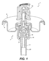
- FIG. 1 is a cross-sectional perspective view of a first embodiment of the valve of the present invention.
- FIG. 2 is a front view of the aerosol dispenser assembly of the first embodiment, with the container cut away for clarity.
- FIG. 3 is an exploded view of a conventional aerosol valve assembly and actuator cap, illustrating the individual components.
- an aerosol dispenser assembly generally comprises a container 2 with a valve assembly 4 disposed in the top thereof for selectively dispensing a liquid product from the container 2.
- the valve assembly 4 further comprises a mounting cup 6, a mounting gasket 8, a valve body 10, a valve stem 12, a stem gasket 14, an actuator cap 16, and a return spring 18.
- the actuator cap 16 defines an exit path 28 and an actuator orifice 32.
- the valve stem 12, stem gasket 14, and return spring 18 are disposed within the valve body 10 and are movable relative to the valve body 10.
- the valve body 10 is affixed to the underside of the mounting cup 6, such that the valve stem 12 extends through, and projects outwardly from, the mounting cup 6.
- the actuator cap 16 is fitted onto the outwardly projecting portion of the valve stem 12, and a dip tube 20 is attached to the lower portion of the valve body 10.
- the whole valve assembly 4 is sealed to the container 2 by mounting gasket 8.
- dispenser assembly shown in FIG. 1 employs a vertical action-type cap 16
- any suitable valve type may be used, such as, for example, a tilt action-type cap.
- any suitable actuator may be used, such as, for example, an actuator button with an integral overcap, a trigger actuated assembly, or the like.
- the actuator cap 16 of the dispenser 1 In operation, when the actuator cap 16 of the dispenser 1 is depressed, it forces the valve stem 12 to move downward, thereby allowing the liquid product to be dispensed.
- the propellant forces the liquid product up the dip tube 20 and into the valve body 10 via body orifice 22.
- the liquid product In the valve body 10, the liquid product is mixed with additional propellant supplied to the valve body 10 through a vapor tap 24.
- the additional propellant introduced through the vapor tap 24 prevents flashing of the liquefied propellant, and increases the amount of pressure drop across the exit orifice which simultaneously increase the particle break-up. From the valve body 10, the liquid product is propelled through at least one stem orifice 26, out the valve stem 12, and through an exit path 28 formed in the actuator cap 16.
- a single stem orifice may be used; however, we have found that using two (as shown in FIG. 1 ), or preferably four, stem orifices 26 spaced around the periphery of the valve body 10 facilitates greater flow and superior mixing of the product as it is dispensed.
- FIG. 1 depicts a breakup bar 30 in the exit path 28, such that the product is forced to diverge around the breakup bar 30, thereby inducing turbulence in the flow of the product, further reducing the particle size of the product.
- the product is then expelled from the actuator cap 16 through an actuator orifice 32, which disperses the product and produces a desired spray pattern.
- the dispenser assembly might employ a pair of breakup plates positioned in or below the exit path 28, a swirl chamber positioned immediately upstream of the exit orifice 32, or other similar mechanical breakup features.
- mechanical breakup features provide some additional break-up of the product prior to being dispensed, we have found that other factors have a much greater impact on particle size than these mechanical breakup features. Nonetheless, these mechanical breakup features may be used to even further reduce the size of the dispensed particles, but such mechanical breakup features are not necessary or preferred.
- A-Series and B-Series propellants both types were found to be suitable for dispensing a liquid product from a container.
- A-Series propellants that we tested unexpectedly produced a mist having a significantly smaller particle size than did the B-series propellants, under the same conditions. This difference was especially pronounced toward the end of the life of the dispenser assembly, when the pressure remaining in the container was lower.
- the superior mist producing ability of the A-Series propellants is due to the absence of normal butane in the A-Series propellants.
- the B-Series propellants contain a combination of propane, normal butane, and isobutane.
- the A-series propellant does not contain any normal butane.
- the liquid product and the propellant form an oil-out emulsion. That is, small droplets of the liquid product are coated with a layer of fragrance oil and propellant, the aqueous phase liquid product being suspended in a layer of non-aqueous phase propellant and fragrance oil.
- the liquefied gas instantly evaporates, causing the droplets to "burst" and creating a fine mist of liquid product in the air.
- HFC hydrogen fluoride
- DME dimethyl ether
- CFC propellants might also be used in connection with a variation of the dispenser assembly of our invention.
- A-Series propellants which are free from normal butane, exhibit reduced particle size of the dispensed product.
- a dispenser assembly having a can pressure of between 55 psig (3.74 atm) and 120 psig (8.17 atm) was found to help reduce product retention while also reducing the particle size of the dispensed product.
- can pressure refers to the initial gauge pressure contained within the aerosol container. Still higher pressures could also be effectively used to dispense the liquid product from the container.
- the strength of the aerosol dispenser container also referred to as an aerosol can
- Federal regulations govern the strength of pressurized containers and specify that aerosol cans must meet a certain can rating for a given internal pressure.
- aerosol cans having an internal pressure of 140 psig or less at 130 °F (9.53 atm at 327 K) are known as "regular" or “unrated,” since a higher DOT rating is not required.
- Aerosol cans having an internal pressure of 160 psig or less at 130 °F (10.9 atm at 344 K) have a DOT rating of 2P
- cans having an internal pressure of 180 psig or less at 130 °F (12.3 atm at 355 K) have a DOT rating of 2Q.
- a can having a higher rating will be more costly due to increased material and/or manufacturing costs.
- the dispenser assembly of FIG. 1 was capable of satisfactorily dispensing an aerosol product that contains at most 25% by weight of a liquefied gas propellant, when the diameter of the vapor tap 24 is between about 0.013" (0.330 mm) and about 0.019" (0.483 mm), the diameter of the stem orifice 26 is between about 0.020" (0.508 mm) and about 0.030" (0.762 mm) when a single stem orifice is used (between about 0.014" (0.356 mm) and about 0.025" (0.635 mm) when a pair of stem orifices are used), the diameter of the body orifice is between about 0.050" (1.270 mm) and about 0.062" (1.575 mm), the diameter of the exit orifice 32 is between about 0.015" (0.381 mm) and about 0.022" (0.559 mm), and the inner diameter of the dip tube is between about 0.040" (1.016 mm) and about 0.060" (1.524
- valve components any of the above-described valve components, propellant types, propellant pressures, and valve orifice dimensions, may be used in combination to provide a dispenser assembly.
- the aerosol dispenser assembly 1 uses an A-Series propellant having a propellant pressure of about 60 psig (4.1 atm) (i.e., A-60 propellant) to dispense the liquid product from the container 2.
- the container is initially pressurized to a can pressure of about 70 psig (4.8 atm) to about 80 psig (5.4 atm).
- the diameter of the vapor tap 24 in this embodiment is about 0.016" (0.406 mm).
- Two stem orifices 26 are used, each having a diameter of about 0.024" (0.610 mm).
- the diameter of the body orifice is about 0.050" (1.270 mm)
- the diameter of the exit orifice 32 is about 0.020" (0.508 mm)
- the inner diameter of the dip tube is about 0.060" (1.52 mm).
- a breakup bar 30 is positioned in the exit path 28 of the actuator 16 in order to further reduce the particle size of the dispensed product.
- a second example employs a single stem orifice 26.
- the dispenser assembly 1 also uses the A-60 propellant and a can pressure of about 70 psig (4.8 atm) to about 80 psig (5.4 atm) to dispense the liquid product from the container 2.
- the diameter of the vapor tap is about 0.016" (0.406 mm)
- the diameter of the single stem orifice is about 0.025" (0.635 mm)
- the diameter of the body orifice is about 0.062" (1.575 mm)
- the inner diameter of the dip tube is about 0.060" (1.524 mm).
- This example also employs a breakup bar, positioned in the exit path of the actuator to further reduce the particle size of the dispensed product.
- T.1 describes the performance of the dispenser assemblies according to the first and second examples, respectively.
- the dispenser assembly is capable of dispensing the liquid product contained within the container as a mist having an average particle size of less than 35 micrometers (0.0014"), over at least 75% of the life of the dispenser assembly. Because the dispensed mist has such a small particle size, the particles are more easily dispersed in the air and less fallout is experienced. This reduction in the amount of fallout increases the dispenser assembly's air freshening efficacy and helps to prevent undesirable residue of the liquid product from settling on flat surfaces, such as, countertops, tables, or floors.
- the dispenser assembly is capable of dispensing over 98% by weight of the liquid product from the container. It is important that substantially all of the product can be dispensed, to ensure that product label claims will be met. Also, by minimizing the amount of product retained in the container at the end of the life of the dispenser assembly, less liquid product is wasted. This is important from a consumer satisfaction standpoint, since consumers tend to be more satisfied with a dispenser assembly when substantially all of the liquid product can be dispensed.
- a water-out emulstion contains small droplets of a non-aqueous phase suspended in an aqueous phase.
- this inversion can be prevented by adjusting the emulsifier. For example, lowering the liquefied gas propellant level from 25% to 10% inverted the emulsion. Addition of 0.03% by weight of trimethyl stearyl ammonium chloride prevented the inversion.
- various other stabilizers in various different amounts may also be effectively used to prevent the inversion of the emulsion.
- performance characteristics upon which to measure the performance of a given dispenser assembly configuration.
- the performance characteristics identified were (1) the average diameter D in micrometers of particles dispensed during the first forty seconds of spray of the assembly, (2) the average spray rate Q in grams/second during the first forty seconds of spray of the assembly, and (3) the amount of the product R remaining in the container at the end of the life of the assembly, expressed as a percentage of the initial fill weight.
- fill weight refers to the weight of all of the contents of the container, including both the liquid product and the propellant.
- the particle size, D should preferably be in the range of about 15 and about 60 micrometers, more preferably between about 25 and about 40 micrometers, and most preferably between about 30 and about 35 micrometers.
- the spray rate is preferably between about 0.6 and about 1.8 g/s, more preferably between about 0.7 and about 1.4 g/s, and most preferably between about 1.0 and about 1.3 g/s.
- the amount of liquid product remaining in the can at the end of life of the dispenser assembly is preferably less than about 3% of the initial fill weight, more preferably less than about 2% of the initial fill weight, and most preferably less than about 1% of the initial fill weight.
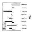
- critical factors the five factors having the greatest effect (negative or positive) on the performance characteristics to perform further experimentation.
- the critical factors selected were dip tube inner diameter, vapor tap diameter, body orifice diameter, stem orifice diameter, and exit orifice diameter.
- the body orifice diameter should preferably be between about 0.010" (0.254 mm) and about 0.025" (0.635 mm), and more preferably between about 0.010" (0.254 mm) and about 0.015" (0.381 mm).
- the vapor tap diameter should preferably be between about 0.003" (0.076 mm) and about 0.010" (0.254 mm), and more preferably between about 0.005" (0.127 mm) and about 0.008" (0.203 mm).
- the at least one stem orifice should preferably have a total area of at least about 0.000628 in 2 (0.405 mm 2 ), and more preferably at least about 0.000905 in 2 (0.584 mm 2 ).
- the exit orifice diameter should preferably be between about 0.013" (0.330 mm) and about 0.025" (0.635 mm), and more preferably between about 0.015" (0.381 mm) and about 0.022" (0.559 mm).
- the dip tube inner diameter should preferably be between about 0.040" (1.016 mm) and about 0.122" (3.099 mm), and more preferably between about 0.050" (1.270 mm) and about 0.090" (2.286 mm).
- valve orifice dimensions minimized the value of CV and provided the best performance at a propellant content of 14.5%.
- a valve according to an embodiment having a body orifice diameter of about 0.013" (0.330 mm), a vapor tap diameter of about 0.005" (0.127 mm), an exit orifice diameter of about 0.018" (0.457 mm), a dip tube inner diameter of about 0.060" (1.524 mm), and at least one stem orifice having a total area of at least about 0.002827" (1.824 mm) provided the best performance for an aerosol air freshener.
- This embodiment is substantially the same as the examples given above in many respects, the main differences being the lower possible propellant content and the different ranges of orifice sizes.
- A-60 propellant was again used as the propellant, and a swirl chamber mechanical breakup element was employed. Of course, no such mechanical breakup element is required.
Landscapes
- Chemical & Material Sciences (AREA)
- Dispersion Chemistry (AREA)
- Engineering & Computer Science (AREA)
- Mechanical Engineering (AREA)
- Containers And Packaging Bodies Having A Special Means To Remove Contents (AREA)
- Cosmetics (AREA)
Claims (13)
- Spenderanordnung für Aerosole mit:einem Behälter (2), der ein flüssiges Erzeugnis und ein verflüssigtes Treibgas enthält, um das flüssige Erzeugnis aus dem Behälter zu treiben, wobei das Treibmittel in einer Menge von höchstens ungefähr 25 % in Massenanteilen des Inhalts des Behälters vorliegt; und miteinem Ventil (4), das an dem Behälter angebracht ist, um das flüssige Erzeugnis und das Treibmittel wahlweise aus dem Behälter abzugeben, wobei das Ventil umfasst:(a) einen Ventilkörper (10) mit i) einer Körperöffnung (22) mit einem Durchmesser von ungefähr 0,254 mm und ungefähr 0,635 mm für den Fluss des flüssigen Erzeugnisses und des Treibmittels während der Abgabe, und mit ii) einem Dampfeinlass (24) mit einem Durchmesser zwischen ungefähr 0,076 mm und ungefähr 0,254 mm, um zusätzliches Treibgas durch den Ventilkörper (10) zuzuführen, um das Mischen des Treibmittels und des flüssigen Erzeugnisses vor der Abgabe zu fördern; und(b) einen Ventilschaft (12), der in dem Ventil (4) angeordnet ist und mindestens eine Schaftöffnung (26) definiert, die eine Gesamtfläche von mindestens 0,405 mm2 für den Fluss des flüssigen Erzeugnisses und des Treibmittels während der Abgabe aufweist; und miteiner Spenderkappe (16), die mit dem Ventilschaft (16) verbunden ist, um das Ventil (4) zu betätigen, das flüssige Erzeugnis abzugeben, wobei die Spenderkappe (16) eine Austrittsöffnung (32) definiert, die einen Durchmesser zwischen ungefähr 0,330 mm und ungefähr 0,635 mm aufweist, durch die das flüssige Erzeugnis und das Treibmittel abgegeben werden.
- Spenderanordnung für Aerosole nach Anspruch 1, bei der das flüssige Treibgas eine Öl-Wasser-Emulsion bildet und weiterhin ein Stabilisator in einer Menge bereitgestellt wird, die wirksam ist, eine Inversion der Emulsion von einer Öl-außen zu einer Wasser-außen Emulsion zu verhindern.
- Spenderanordnung für Aerosole nach Anspruch 2, bei der der Stabilisator 0,03 % in Massenanteilen von Trimethylstearylamoniumchlorid ist.
- Spenderanordnung für Aerosole nach einem der vorhergehenden Ansprüche, bei der das Treibmittel einen Kohlenwasserstoff-Treibmittel ist.
- Spenderanordnung für Aerosole nach einem der vorhergehenden Ansprüche, bei der die Körperöffnung (22) einen Durchmesser zwischen ungefähr 0,330 mm und ungefähr 0,381 mm aufweist, vorzugsweise 0,33 mm.
- Spenderanordnung für Aerosole nach einem der Ansprüche 1-4, bei der der Dampfeinlass (24) einen Durchmesser zwischen ungefähr 0,127 mm und ungefähr 0,203 mm aufweist, vorzugsweise ungefähr 0,127 mm.
- Spenderanordnung für Aerosole nach einem der Ansprüche 1-4, bei der die mindestens eine Schaftöffnung (26) eine Gesamtfläche von mindestens ungefähr 0,584 mm2 aufweist, vorzugsweise mindestens 1,824 mm2.
- Spenderanordnung für Aerosole nach einem der Ansprüche 1-4, bei der die Austrittsöffnung (32) einen Durchmesser zwischen ungefähr 0,381 mm und ungefähr 0,559 mm aufweist, vorzugsweise 0,457 mm.
- Spenderanordnung für Aerosole nach einem der vorhergehenden Ansprüche, die weiterhin ein Tauchrohr (20) aufweist, das mit der Unterseite des Ventilkörpers (10) verbunden ist und sich in Richtung der Unterseite des Behälters erstreckt, wobei das Tauchrohr einen inneren Durchmesser zwischen ungefähr 1,016 mm und ungefähr 3,099 mm aufweist, vorzugsweise zwischen ungefähr 1,270 mm und ungefähr 2,286 mm, und besonders bevorzugt ungefähr 1,524 mm.
- Spenderanordnung für Aerosole nach einem der vorhergehenden Ansprüche, bei der das Treibmittel in einer Menge von zwischen ungefähr 10 % und ungefähr 25 % in Massenanteilen des Inhalts des Behälters vorliegt.
- Spenderanordnung für Aerosole nach Anspruch 10, bei der das Treibmittel in einer Menge von zwischen ungefähr 10 % und ungefähr 15 % in Massenanteilen des Inhalts des Behälters vorliegt.
- Spenderanordnung für Aerosole nach Anspruch 11, bei der das Treibmittel in einer Menge von 15 % vorliegt.
- Spenderanordnung für Aerosole nach Anspruch 1, bei der die Körperöffnung (22) einen Durchmesser zwischen ungefähr 0,330 mm und ungefähr 0,381 mm aufweist, der Dampfeinlass (24) einen Durchmesser zwischen ungefähr 0,127 mm und ungefähr 0,203 mm aufweist, der mindestens einen Ventilschaft (26) mit einer Gesamtfläche von mindestens ungefähr 0,584 mm2 aufweist, die Austrittsöffnung (32) einen Durchmesser zwischen ungefähr 0,381 mm und ungefähr 0,559 mm aufweist, wobei das Treibmittel in einer Menge von 10-25 % bezogen auf das Gewicht des Inhalts des Behälters vorliegt.
Priority Applications (1)
| Application Number | Priority Date | Filing Date | Title |
|---|---|---|---|
| EP10163221A EP2228318A1 (de) | 2003-01-24 | 2004-01-22 | Ausgabeanordnung für Aerosole mit einer gering flüchtigen organischen Verbindung |
Applications Claiming Priority (5)
| Application Number | Priority Date | Filing Date | Title |
|---|---|---|---|
| US350011 | 2003-01-24 | ||
| US10/350,011 US6824079B2 (en) | 2003-01-24 | 2003-01-24 | Aerosol dispenser assembly and method of reducing the particle size of a dispensed product |
| US10/653,211 US7014127B2 (en) | 2003-01-24 | 2003-09-03 | Aerosol dispenser assembly having low volatile organic compound (VOC) content |
| US653211 | 2003-09-03 | ||
| PCT/US2004/001953 WO2004067406A1 (en) | 2003-01-24 | 2004-01-22 | Dispenser assembly for aerosols having low volatile organic compound (voc) content |
Publications (2)
| Publication Number | Publication Date |
|---|---|
| EP1590268A1 EP1590268A1 (de) | 2005-11-02 |
| EP1590268B1 true EP1590268B1 (de) | 2010-06-02 |
Family
ID=32735478
Family Applications (2)
| Application Number | Title | Priority Date | Filing Date |
|---|---|---|---|
| EP04704493A Expired - Lifetime EP1590268B1 (de) | 2003-01-24 | 2004-01-22 | Spenderanordnung für aerosole mit geringem anteil an flüchtigen organischen verbindungen (voc) |
| EP10163221A Withdrawn EP2228318A1 (de) | 2003-01-24 | 2004-01-22 | Ausgabeanordnung für Aerosole mit einer gering flüchtigen organischen Verbindung |
Family Applications After (1)
| Application Number | Title | Priority Date | Filing Date |
|---|---|---|---|
| EP10163221A Withdrawn EP2228318A1 (de) | 2003-01-24 | 2004-01-22 | Ausgabeanordnung für Aerosole mit einer gering flüchtigen organischen Verbindung |
Country Status (7)
| Country | Link |
|---|---|
| US (2) | US6824079B2 (de) |
| EP (2) | EP1590268B1 (de) |
| JP (1) | JP2006517894A (de) |
| AT (1) | ATE469845T1 (de) |
| DE (1) | DE602004027461D1 (de) |
| ES (1) | ES2346880T3 (de) |
| WO (1) | WO2004067406A1 (de) |
Cited By (1)
| Publication number | Priority date | Publication date | Assignee | Title |
|---|---|---|---|---|
| WO2023244242A1 (en) * | 2022-06-17 | 2023-12-21 | Reckitt Benckiser Llc | Instant action aerosol for air sanitization and disinfection |
Families Citing this family (88)
| Publication number | Priority date | Publication date | Assignee | Title |
|---|---|---|---|---|
| US7278590B1 (en) | 1992-02-24 | 2007-10-09 | Homax Products, Inc. | Systems and methods for applying texture material to ceiling surfaces |
| WO2002083321A1 (en) * | 2001-04-13 | 2002-10-24 | Daizo Corporation | Aerosol product |
| US6824079B2 (en) * | 2003-01-24 | 2004-11-30 | S. C. Johnson & Son, Inc. | Aerosol dispenser assembly and method of reducing the particle size of a dispensed product |
| US20050023368A1 (en) * | 2003-01-24 | 2005-02-03 | S.C. Johnson & Son, Inc. | Method of designing improved spray dispenser assemblies |
| US7998403B2 (en) * | 2003-05-05 | 2011-08-16 | The Proctor & Gamble Company | Method of freshening air |
| US7677420B1 (en) | 2004-07-02 | 2010-03-16 | Homax Products, Inc. | Aerosol spray texture apparatus for a particulate containing material |
| US7487893B1 (en) | 2004-10-08 | 2009-02-10 | Homax Products, Inc. | Aerosol systems and methods for dispensing texture material |
| WO2006059080A1 (en) * | 2004-12-02 | 2006-06-08 | Keith Laidler | A valve for a pressurised dispenser and a pressurised dispenser comprising such a valve |
| AU2006263681C1 (en) * | 2005-06-28 | 2012-07-19 | S. C. Johnson & Son, Inc. | A composition and its physical requirements for eliminating odors in air |
| US8465728B2 (en) | 2005-06-28 | 2013-06-18 | S.C. Johnson & Son, Inc. | Composition and aerosol spray dispenser for eliminating odors in air |
| GB0522287D0 (en) * | 2005-11-01 | 2005-12-07 | Reckitt Benckiser Uk Ltd | Method and compositions |
| US7445136B2 (en) * | 2006-03-02 | 2008-11-04 | Arlo Lin | Valve for gas can |
| US7448517B2 (en) * | 2006-05-31 | 2008-11-11 | The Clorox Company | Compressed gas propellants in plastic aerosols |
| US11040360B2 (en) | 2006-06-20 | 2021-06-22 | Saint-Gobain Abrasives, Inc. | Liquid supply assembly |
| DK2029285T3 (da) | 2006-06-20 | 2013-03-11 | Saint Gobain Abrasives Inc | Væsketilførselsanordning |
| US8158108B2 (en) | 2006-06-28 | 2012-04-17 | S.C. Johnson & Son, Inc. | VOC-free compressed gas aerosol compositions |
| TW200806342A (en) * | 2006-06-28 | 2008-02-01 | S C Johnson & Amp Son Inc | Composition and aerosol spray dispenser for eliminating odors in air |
| US20080067262A1 (en) * | 2006-09-14 | 2008-03-20 | S.C. Johnson & Son, Inc. | Aerosol Dispenser Assembly Having VOC-Free Propellant and Dispensing Mechanism Therefor |
| FR2910841B1 (fr) * | 2006-12-28 | 2009-04-10 | Neopost Technologies Sa | Systeme de mouillage par pulverisation de gouttelettes d'eau |
| US7779608B2 (en) * | 2007-02-02 | 2010-08-24 | Lim Walter K | Pressurized containers and methods for filling them |
| US8344056B1 (en) | 2007-04-04 | 2013-01-01 | Homax Products, Inc. | Aerosol dispensing systems, methods, and compositions for repairing interior structure surfaces |
| US9382060B1 (en) | 2007-04-05 | 2016-07-05 | Homax Products, Inc. | Spray texture material compositions, systems, and methods with accelerated dry times |
| US8580349B1 (en) | 2007-04-05 | 2013-11-12 | Homax Products, Inc. | Pigmented spray texture material compositions, systems, and methods |
| US9242256B2 (en) | 2007-07-17 | 2016-01-26 | S.C. Johnson & Son, Inc. | Aerosol dispenser assembly having VOC-free propellant and dispensing mechanism therefor |
| EP2238242B9 (de) | 2008-01-03 | 2015-06-10 | BASF Enzymes LLC | Transferasen und oxidoreduktasen, dafür kodierende nukleinsäuren sowie verfahren zu ihrer herstellung und verwendung |
| US8178078B2 (en) | 2008-06-13 | 2012-05-15 | S.C. Johnson & Son, Inc. | Compositions containing a solvated active agent suitable for dispensing as a compressed gas aerosol |
| US8635873B2 (en) * | 2009-02-27 | 2014-01-28 | D2Bg Llc | Compressed gas-driven device with passive thermodynamic composition |
| US8833078B2 (en) | 2009-02-27 | 2014-09-16 | D2Bg Llc | Compressed gas-driven device with passive thermodynamic composition |
| TWI377307B (en) | 2009-03-26 | 2012-11-21 | Smc Kk | Flow rate control valve and assembly method therefor |
| US8167490B2 (en) | 2009-04-22 | 2012-05-01 | Reynolds Consumer Products Inc. | Multilayer stretchy drawstring |
| GB201006080D0 (en) | 2010-04-13 | 2010-05-26 | Univ Salford The | Aerosol spray device |
| NL2004012C2 (nl) * | 2009-12-23 | 2011-06-27 | Dispensing Technologies Bv | Inrichting voor het vermengen van media, alsmede werkwijze voor de vervaardiging daarvan. |
| US8287841B2 (en) | 2010-06-18 | 2012-10-16 | S.C. Johnson & Son, Inc. | Aerosol odor eliminating compositions containing alkylene glycol(s) |
| US8475769B2 (en) | 2010-06-25 | 2013-07-02 | S.C. Johnson & Son, Inc. | Aerosol composition with enhanced dispersion effects |
| MX2013001257A (es) | 2010-08-02 | 2013-07-02 | Johnson & Son Inc S C | Sistema y método para emitir consistentemente un material volátil. |
| US8877139B2 (en) | 2010-08-13 | 2014-11-04 | The Procter & Gamble Company | Compositions comprising a functional perfume component mixture |
| CA2835088C (en) * | 2011-05-06 | 2018-01-16 | Saint-Gobain Abrasives, Inc. | Paint cup assembly with an extended ring |
| ES2739299T3 (es) | 2011-06-30 | 2020-01-30 | Saint Gobain Abrasives Inc | Conjunto de envase de pintura |
| US9393336B2 (en) | 2011-07-08 | 2016-07-19 | S. C. Johnson & Son, Inc. | Insert for dispensing a compressed gas product, system with such an insert, and method of dispensing a compressed gas product |
| US9156042B2 (en) | 2011-07-29 | 2015-10-13 | Homax Products, Inc. | Systems and methods for dispensing texture material using dual flow adjustment |
| US9248457B2 (en) | 2011-07-29 | 2016-02-02 | Homax Products, Inc. | Systems and methods for dispensing texture material using dual flow adjustment |
| EP2570190A1 (de) | 2011-09-15 | 2013-03-20 | Braun GmbH | Sprühdüse zum Abgeben einer Flüssigkeit und Sprüheinrichtung, die eine solche Sprühdüse umfasst |
| MX2014007887A (es) | 2011-12-30 | 2014-10-06 | Saint Gobain Abrasives Inc | Montaje de copa de pintura convertible con valvula de entrada de aire. |
| US8927474B2 (en) | 2012-03-16 | 2015-01-06 | S.C. Johnson & Son, Inc. | Compressed gas aerosol composition in steel can |
| US9156602B1 (en) | 2012-05-17 | 2015-10-13 | Homax Products, Inc. | Actuators for dispensers for texture material |
| US9204625B2 (en) | 2012-08-17 | 2015-12-08 | S.C. Johnson & Son, Inc. | Dispenser |
| US9435120B2 (en) | 2013-03-13 | 2016-09-06 | Homax Products, Inc. | Acoustic ceiling popcorn texture materials, systems, and methods |
| EP2919746B1 (de) * | 2013-06-28 | 2019-05-29 | The Procter and Gamble Company | Aerosolhaarsprayprodukt mit sprühvorrichtung |
| CA2859537C (en) | 2013-08-19 | 2019-10-29 | Homax Products, Inc. | Ceiling texture materials, systems, and methods |
| US20150335778A1 (en) * | 2014-05-21 | 2015-11-26 | The Procter & Gamble Company | Freshening product comprising an aqueous perfume composition contained in a pressurized plastic container |
| USD787326S1 (en) | 2014-12-09 | 2017-05-23 | Ppg Architectural Finishes, Inc. | Cap with actuator |
| JP7066412B2 (ja) | 2015-04-23 | 2022-05-13 | ザ プロクター アンド ギャンブル カンパニー | 界面活性剤可溶性抗ふけ剤の送達 |
| CN107666898B (zh) | 2015-06-01 | 2021-06-01 | 宝洁公司 | 包括喷洒装置的气溶胶发胶产品 |
| ES2893974T3 (es) | 2016-03-03 | 2022-02-10 | Procter & Gamble | Composición anticaspa en aerosol |
| EP3528894A1 (de) | 2016-10-21 | 2019-08-28 | The Procter and Gamble Company | Konzentrierte shampoodosierung von schaum zur bereitstellung von haarpflegenutzen |
| WO2018075846A1 (en) | 2016-10-21 | 2018-04-26 | The Procter & Gamble Company | Concentrated shampoo dosage of foam designating hair conditioning benefits |
| US11129783B2 (en) | 2016-10-21 | 2021-09-28 | The Procter And Gamble Plaza | Stable compact shampoo products with low viscosity and viscosity reducing agent |
| EP3528774A1 (de) | 2016-10-21 | 2019-08-28 | The Procter and Gamble Company | Konzentrierte shampoo-dosierung von schaum zur bestimmung von haarpflegevorteilen |
| CN109843383A (zh) | 2016-10-21 | 2019-06-04 | 宝洁公司 | 用于在最佳制剂空间中递送消费者期望的剂量体积、表面活性剂量和头皮健康剂量的泡沫剂型 |
| US20180110690A1 (en) | 2016-10-21 | 2018-04-26 | The Procter & Gamble Company | Concentrated Shampoo Dosage of Foam for Providing Hair Care Benefits |
| WO2018075850A1 (en) | 2016-10-21 | 2018-04-26 | The Procter & Gamble Company | Dosage of foam for delivering consumer desired dosage volume and surfactant amount in an optimal formulation space |
| WO2018075861A1 (en) * | 2016-10-21 | 2018-04-26 | The Procter & Gamble Company | Concentrated shampoo comprising a hydrofluoroolefin or a hydrochlorofluoroolefin for delivering compositional and foam dosage property benefits |
| US11679073B2 (en) | 2017-06-06 | 2023-06-20 | The Procter & Gamble Company | Hair compositions providing improved in-use wet feel |
| US11224567B2 (en) | 2017-06-06 | 2022-01-18 | The Procter And Gamble Company | Hair compositions comprising a cationic polymer/silicone mixture providing improved in-use wet feel |
| US11141370B2 (en) | 2017-06-06 | 2021-10-12 | The Procter And Gamble Company | Hair compositions comprising a cationic polymer mixture and providing improved in-use wet feel |
| MX388495B (es) | 2017-10-10 | 2025-03-20 | Procter & Gamble | Composición de champú compacto que contiene surfactantes libres de sulfato. |
| WO2019074988A1 (en) | 2017-10-10 | 2019-04-18 | The Procter & Gamble Company | METHOD OF TREATING HAIR OR SKIN WITH PERSONAL FOAM COMPOSITION IN THE FORM OF FOAM |
| JP2020536876A (ja) | 2017-10-10 | 2020-12-17 | ザ プロクター アンド ギャンブル カンパニーThe Procter & Gamble Company | アミノ酸系アニオン性界面活性剤及びカチオン性ポリマーを含むコンパクトシャンプー組成物 |
| EP3694483B1 (de) | 2017-10-10 | 2022-09-07 | The Procter & Gamble Company | Sulfatfreie klare körperreinigungszusammensetzung mit niedrigem gehalt an anorganischem salz |
| US10912732B2 (en) | 2017-12-20 | 2021-02-09 | The Procter And Gamble Company | Clear shampoo composition containing silicone polymers |
| MX2020014144A (es) | 2018-06-29 | 2021-03-25 | Procter & Gamble | Composicion anticaspa en aerosol con bajo contenido de surfactante. |
| US10486892B1 (en) * | 2018-08-22 | 2019-11-26 | The Procter & Gamble Company | Packages and arrays of packages for plastic aerosol dispensers |
| US12226505B2 (en) | 2018-10-25 | 2025-02-18 | The Procter & Gamble Company | Compositions having enhanced deposition of surfactant-soluble anti-dandruff agents |
| FR3099144B1 (fr) * | 2019-07-24 | 2022-01-07 | Lindal France | Valve pour récipient sous pression |
| CN118323654A (zh) | 2019-07-24 | 2024-07-12 | 林达尔法国两合公司 | 用于压力容器的阀杯 |
| JP7410298B2 (ja) | 2019-12-06 | 2024-01-09 | ザ プロクター アンド ギャンブル カンパニー | 頭皮活性物質の付着を強化する硫酸塩を含まない組成物 |
| CN115151310B (zh) | 2020-02-27 | 2024-12-20 | 宝洁公司 | 功效和美观性增强的含硫去头皮屑组合物 |
| MX2023005560A (es) | 2020-11-23 | 2023-05-29 | Procter & Gamble | Composiciones para el cuidado personal libres de surfactantes sulfatados. |
| US11819474B2 (en) | 2020-12-04 | 2023-11-21 | The Procter & Gamble Company | Hair care compositions comprising malodor reduction materials |
| US11771635B2 (en) | 2021-05-14 | 2023-10-03 | The Procter & Gamble Company | Shampoo composition |
| WO2022249197A1 (en) * | 2021-05-26 | 2022-12-01 | Patel Bhogilal Laljibhai | A valve for aerosol container |
| US11986543B2 (en) | 2021-06-01 | 2024-05-21 | The Procter & Gamble Company | Rinse-off compositions with a surfactant system that is substantially free of sulfate-based surfactants |
| CA3223150A1 (en) * | 2021-06-30 | 2023-01-05 | Reckitt Benckiser Llc | Instant action aerosol for air sanitization and disinfection |
| US12128118B2 (en) | 2021-07-29 | 2024-10-29 | The Procter & Gamble Company | Aerosol dispenser containing a hairspray composition and a nitrogen propellant |
| EP4140594A1 (de) | 2021-08-30 | 2023-03-01 | Beiersdorf AG | Aerosolspray |
| US11957178B2 (en) | 2021-11-15 | 2024-04-16 | Apackaging Group Llc | Aerosol actuator |
| CN118265516A (zh) | 2021-12-09 | 2024-06-28 | 宝洁公司 | 含有效防腐的不含硫酸盐个人清洁组合物 |
| EP4658418A1 (de) * | 2023-01-30 | 2025-12-10 | The Procter & Gamble Company | Aerosolspender enthaltend eine haarsprayzusammensetzung und einen stickstoff-treibstoff |
Family Cites Families (80)
| Publication number | Priority date | Publication date | Assignee | Title |
|---|---|---|---|---|
| US61A (en) * | 1836-10-20 | Machine fob making weavers harness | ||
| US5A (en) * | 1836-08-10 | Thomas Blanchard | Machine for mortising solid wooden shells of ships' tackle-blocks | |
| US59A (en) * | 1836-10-19 | Drawijtg | ||
| US56A (en) * | 1836-10-15 | Dock-plate | ||
| US35843A (en) * | 1862-07-08 | Improvement in brick and tile machines | ||
| US2A (en) * | 1826-12-15 | 1836-07-29 | John Goulding | Mode of manufacturing wool or other fibrous materials |
| US3A (en) * | 1836-08-01 | 1836-08-11 | Thomas Blanchard | Machine for turning and wooden sheaves and pins for ships' tackle blocks and pulleys |
| US3018023A (en) | 1959-02-27 | 1962-01-23 | Rudolph D Talarico | Fluid dispensing apparatus |
| US3137416A (en) | 1961-03-15 | 1964-06-16 | Aerosol Tech Inc | Composition for aerosol dispenser consisting of two immiscible liquid phases |
| US3544258A (en) | 1963-08-19 | 1970-12-01 | Aerosol Tech Inc | Self-propelled liquid dispenser containing an antiperspirant aluminum salt |
| US3635261A (en) * | 1968-08-01 | 1972-01-18 | Oreal | Method and apparatus for packaging products which are to be stored separately but dispensed simultaneously |
| FR2031791A6 (de) * | 1968-12-11 | 1970-11-20 | Oreal | |
| US3648932A (en) * | 1969-10-27 | 1972-03-14 | Pittway Corp | Valve button with aspirator passageway |
| US3583642A (en) * | 1969-12-10 | 1971-06-08 | Johnson & Son Inc S C | Spray head for an aerosol dispenser |
| US3647119A (en) | 1970-05-26 | 1972-03-07 | S C John & Son Inc | Pressurized package |
| US3715081A (en) * | 1971-03-26 | 1973-02-06 | E Green | Aerosol valve and sprayhead |
| US4056500A (en) | 1971-08-04 | 1977-11-01 | Martin Paint And Chemical Corporation | Aerosol-dispensed latex paint compositions |
| US4174386A (en) | 1975-03-03 | 1979-11-13 | Marra Dorothea C | Aerosol antiperspirant compositions with good adherence to the skin |
| US4019657A (en) | 1975-03-03 | 1977-04-26 | Spitzer Joseph G | Aerosol containers for foaming and delivering aerosols |
| US4141472A (en) | 1976-07-19 | 1979-02-27 | Spitzer Joseph G | Aerosol container with gas-permeable membrane |
| US4124149A (en) | 1976-07-19 | 1978-11-07 | Spitzer Joseph G | Aerosol container with position-sensitive shut-off valve |
| US4152416A (en) | 1976-09-17 | 1979-05-01 | Marra Dorothea C | Aerosol antiperspirant compositions delivering astringent salt with low mistiness and dustiness |
| US4117958A (en) | 1976-12-27 | 1978-10-03 | Spitzer Joseph G | Vapor tap valve for aerosol containers used with flammable propellants |
| US4431120A (en) | 1977-04-28 | 1984-02-14 | Nicholas A. Mardesich | Packaging system |
| US4680173A (en) | 1977-04-28 | 1987-07-14 | Norman D. Burger | Aerosol dispensing system |
| US4230243A (en) | 1978-08-08 | 1980-10-28 | Spitzer Joseph G | Aerosol container with flameless delivery valve |
| US4203552A (en) * | 1978-09-05 | 1980-05-20 | Ethyl Corporation | Pressurized atomizer |
| DE2849599A1 (de) | 1978-11-15 | 1980-05-22 | Schwarzkopf Gmbh Hans | Aerosoldose mit einem feinstvernebelungsventil mit einer treibmittel enthaltenden fuellung, verfahren zu ihrer herstellung sowie ihre verwendung |
| JPS56133065A (en) | 1980-03-21 | 1981-10-17 | Earth Chem Corp Ltd | Upright invertible injection aerosol |
| AU8734582A (en) * | 1981-06-04 | 1982-12-07 | Pharmasol Corp., The | Dispensing system |
| JPS5984801A (ja) | 1982-11-08 | 1984-05-16 | Sumitomo Chem Co Ltd | 空間用害虫駆除エアゾ−ル剤 |
| JPS5984802A (ja) | 1982-11-08 | 1984-05-16 | Sumitomo Chem Co Ltd | 空間用害虫駆除エアゾ−ル剤 |
| JPS609001B2 (ja) | 1982-11-17 | 1985-03-07 | 株式会社 丸一製作所 | エヤゾ−ル殺虫剤 |
| JPS5948802B2 (ja) | 1982-11-17 | 1984-11-29 | 株式会社 丸一製作所 | エヤゾ−ル殺虫剤 |
| US4534958A (en) | 1983-07-13 | 1985-08-13 | Basf Wyandotte Corporation | Aerosol gel |
| JPS61161164A (ja) | 1984-12-29 | 1986-07-21 | Toyo Aerosol Kogyo Kk | エアゾ−ル製品 |
| JPS61165320A (ja) | 1985-01-16 | 1986-07-26 | Toyo Aerosol Kogyo Kk | 粉末エアゾ−ル製品 |
| US4935224A (en) | 1988-05-26 | 1990-06-19 | The Mennen Company | Aerosol antiperspirant composition, including substantivity fluid, capable of being dispensed at reduced spray rate, and packaged aerosol antiperspirant |
| GB8909312D0 (en) | 1988-11-22 | 1989-06-07 | Dunne Stephen T | Liquid-gas mixing device |
| JPH02294382A (ja) | 1989-05-09 | 1990-12-05 | Kao Corp | エアゾール製品 |
| US4940171A (en) | 1989-05-18 | 1990-07-10 | Gilroy Gordon C | Aerosol package having compressed gas propellant and vapor tap of minute size |
| US5082652A (en) | 1989-08-22 | 1992-01-21 | Larry Mayfield | Aerosol deodorant composition and packaged aerosol deodorant |
| GB8921745D0 (en) | 1989-09-27 | 1989-11-08 | Aerosol Inventions Dev | Pressurised dispensers |
| JP2898316B2 (ja) | 1989-11-01 | 1999-05-31 | 株式会社大阪造船所 | 人体用エヤゾール製品 |
| JP2795354B2 (ja) | 1989-11-14 | 1998-09-10 | 東洋エアゾール工業株式会社 | 人体用エアゾール製品 |
| JP3148212B2 (ja) | 1989-12-06 | 2001-03-19 | 古河電気工業株式会社 | 超電導成形撚線の製造方法 |
| US5068099A (en) | 1990-01-16 | 1991-11-26 | S. C. Johnson & Son, Inc. | Hair spray package with low volatile organic compound emission |
| US5314097A (en) | 1990-04-23 | 1994-05-24 | Fox Valley Systems, Inc. | Long distance marking devices and related method |
| US5083683A (en) * | 1990-11-26 | 1992-01-28 | Calmar Inc. | Fingertip sprayer mounted on an angled neck container |
| JPH0542979A (ja) * | 1991-08-08 | 1993-02-23 | Toyama Chem Co Ltd | 液体噴射ボンベ |
| JPH0542797A (ja) | 1991-08-09 | 1993-02-23 | Janome Sewing Mach Co Ltd | 毛筆描画装置 |
| FR2684358B1 (fr) | 1991-12-02 | 1995-01-20 | Oreal | Dispositif aerosol pour distribuer une composition a viscosite relativement elevee. |
| US5639441A (en) | 1992-03-06 | 1997-06-17 | Board Of Regents Of University Of Colorado | Methods for fine particle formation |
| US5211317A (en) | 1992-06-18 | 1993-05-18 | Diamond George Bernard | Low pressure non-barrier type, valved dispensing can |
| US5340871A (en) | 1993-01-29 | 1994-08-23 | The Sherwin-Williams Company | Aerosol compositions containing non-aqueous dispersions |
| US5348992A (en) | 1993-01-29 | 1994-09-20 | The Sherwin-Williams Company | Aerosol compositions containing non-aqueous dispersions |
| US5304368A (en) | 1993-02-19 | 1994-04-19 | American Telecast Corporation | Non-foaming, non-viscous, alcohol-free, water-based, pressurized hair spray product |
| JP3157328B2 (ja) | 1993-03-04 | 2001-04-16 | ローム株式会社 | 電子部品用リード電極の切断バリ除去方法 |
| US5626840A (en) | 1993-04-06 | 1997-05-06 | National Starch And Chemical Investment Holding Corporation | Use of polyurethanes with carboxylate functionality for hair fixative applications |
| US5586695A (en) | 1993-10-07 | 1996-12-24 | Labus; Rainer H. | Sprayed liquid dispensing apparatus |
| US5518151A (en) | 1994-04-25 | 1996-05-21 | Aptar Group, Inc. | Dip tube for hand operated dispensing device |
| US5939060A (en) * | 1994-08-12 | 1999-08-17 | The Procter & Gamble Company | Composition for reducing malodor impression on inanimate surfaces |
| US5988455A (en) | 1994-12-16 | 1999-11-23 | The Sherwin-Williams Company | Latex aerosol paint products |
| US5603919A (en) | 1995-01-05 | 1997-02-18 | Isp Investments Inc. | Low VOC hair spray fixative compositions containing a tetramer |
| JPH0967204A (ja) | 1995-09-04 | 1997-03-11 | Fumakilla Ltd | ケムシ防除用エアゾル剤 |
| FR2743356B1 (fr) | 1996-01-10 | 1998-02-13 | Oreal | Dispositif de produit de consistance liquide a pateuse comportant un dispositif de securite |
| FR2749568B1 (fr) | 1996-06-10 | 1998-08-07 | Oreal | Distributeur de produit liquide a polymere filmogene sous forme de fines gouttelettes |
| DE19636221C2 (de) | 1996-09-06 | 1999-02-04 | Peter Kwasny Gmbh | Sprühdose |
| JP3968127B2 (ja) | 1997-07-04 | 2007-08-29 | ユニヴァーシティー オヴ サウザンプトン | 殺虫剤による飛んでいる虫の的中を改善する方法及び液体を帯電させるための装置 |
| US6352582B1 (en) * | 1997-10-22 | 2002-03-05 | S.C. Johnson & Son, Inc. | Composition and process for treating hard surfaces |
| US6112633A (en) * | 1998-06-22 | 2000-09-05 | Trocino; Joseph | Disposable explosive foam dispenser |
| GB9814372D0 (en) * | 1998-07-02 | 1998-09-02 | Reckitt & Colmann Prod Ltd | Treatment of airborne allergens |
| US5984801A (en) * | 1998-08-05 | 1999-11-16 | Mason; Robert B. | Golf alignment training apparatus and method |
| DE19850146A1 (de) | 1998-10-30 | 2000-05-11 | Coster Tecnologie Speciali Spa | Ventil für die Abgabe von unter Druck stehenden Flüssigkeiten |
| JP2000316471A (ja) | 1999-05-07 | 2000-11-21 | Kyowa Industrial Co Ltd | エアゾール容器入りの食用油 |
| US6260738B1 (en) * | 1999-06-15 | 2001-07-17 | The Procter & Gamble Company | Nozzle having upward moving straw while communicating upright dispensing |
| US6358893B1 (en) | 2000-06-20 | 2002-03-19 | Stoner, Inc. | Aerosol composition containing silicone-based fluid and improved spray system |
| US6357633B1 (en) | 2000-07-18 | 2002-03-19 | Precision Valve Corporation | Fast opening aerosol valve |
| US6394321B1 (en) | 2001-12-20 | 2002-05-28 | Precision Valve Corporation | Aerosol powder valve |
| US6824079B2 (en) * | 2003-01-24 | 2004-11-30 | S. C. Johnson & Son, Inc. | Aerosol dispenser assembly and method of reducing the particle size of a dispensed product |
-
2003
- 2003-01-24 US US10/350,011 patent/US6824079B2/en not_active Expired - Lifetime
- 2003-09-03 US US10/653,211 patent/US7014127B2/en not_active Expired - Lifetime
-
2004
- 2004-01-22 JP JP2006502979A patent/JP2006517894A/ja active Pending
- 2004-01-22 EP EP04704493A patent/EP1590268B1/de not_active Expired - Lifetime
- 2004-01-22 DE DE602004027461T patent/DE602004027461D1/de not_active Expired - Lifetime
- 2004-01-22 EP EP10163221A patent/EP2228318A1/de not_active Withdrawn
- 2004-01-22 AT AT04704493T patent/ATE469845T1/de not_active IP Right Cessation
- 2004-01-22 ES ES04704493T patent/ES2346880T3/es not_active Expired - Lifetime
- 2004-01-22 WO PCT/US2004/001953 patent/WO2004067406A1/en not_active Ceased
Cited By (1)
| Publication number | Priority date | Publication date | Assignee | Title |
|---|---|---|---|---|
| WO2023244242A1 (en) * | 2022-06-17 | 2023-12-21 | Reckitt Benckiser Llc | Instant action aerosol for air sanitization and disinfection |
Also Published As
| Publication number | Publication date |
|---|---|
| EP2228318A1 (de) | 2010-09-15 |
| WO2004067406A1 (en) | 2004-08-12 |
| EP1590268A1 (de) | 2005-11-02 |
| US7014127B2 (en) | 2006-03-21 |
| US20040144864A1 (en) | 2004-07-29 |
| JP2006517894A (ja) | 2006-08-03 |
| ES2346880T3 (es) | 2010-10-21 |
| DE602004027461D1 (de) | 2010-07-15 |
| US6824079B2 (en) | 2004-11-30 |
| ATE469845T1 (de) | 2010-06-15 |
| US20040144863A1 (en) | 2004-07-29 |
Similar Documents
| Publication | Publication Date | Title |
|---|---|---|
| US7014127B2 (en) | Aerosol dispenser assembly having low volatile organic compound (VOC) content | |
| US9242256B2 (en) | Aerosol dispenser assembly having VOC-free propellant and dispensing mechanism therefor | |
| AU2006310297B2 (en) | Aerosol composition and method | |
| US5143288A (en) | Compressed gas aerosol spray system with a dip tube vapor tap hole | |
| US20050023368A1 (en) | Method of designing improved spray dispenser assemblies | |
| US7593790B2 (en) | Method for designing aerosol spray dispensers | |
| EP1896087B1 (de) | Aerosolabgabeanordnung | |
| US12569425B2 (en) | Aerosol hair care product | |
| US20220402685A1 (en) | Dispensing systems | |
| US20080067262A1 (en) | Aerosol Dispenser Assembly Having VOC-Free Propellant and Dispensing Mechanism Therefor | |
| CA1048453A (en) | Aerosol containers for delivering high active concentration aerosol compositions at a low delivery rate | |
| US20050020698A1 (en) | Reduced VOC two-phase aerosol space spray products | |
| CA2512424A1 (en) | Method of designing improved spray dispenser assemblies | |
| KR20230145574A (ko) | 에어로졸 스프레이, 에어로졸 스프레이 생성 방법,및 에어로졸 디스펜싱 시스템 | |
| JP2001172616A (ja) | 全量噴射型のエアゾール製品 | |
| CA2602880A1 (en) | Aerosol dispenser assembly having voc-free propellant and dispensing mechanism therefor | |
| WO2017123565A1 (en) | Stand-and-spray foam delivery method and device thereof |
Legal Events
| Date | Code | Title | Description |
|---|---|---|---|
| PUAI | Public reference made under article 153(3) epc to a published international application that has entered the european phase |
Free format text: ORIGINAL CODE: 0009012 |
|
| 17P | Request for examination filed |
Effective date: 20050808 |
|
| AK | Designated contracting states |
Kind code of ref document: A1 Designated state(s): AT BE BG CH CY CZ DE DK EE ES FI FR GB GR HU IE IT LI LU MC NL PT RO SE SI SK TR |
|
| AX | Request for extension of the european patent |
Extension state: AL LT LV MK |
|
| DAX | Request for extension of the european patent (deleted) | ||
| GRAP | Despatch of communication of intention to grant a patent |
Free format text: ORIGINAL CODE: EPIDOSNIGR1 |
|
| GRAS | Grant fee paid |
Free format text: ORIGINAL CODE: EPIDOSNIGR3 |
|
| GRAA | (expected) grant |
Free format text: ORIGINAL CODE: 0009210 |
|
| AK | Designated contracting states |
Kind code of ref document: B1 Designated state(s): AT BE BG CH CY CZ DE DK EE ES FI FR GB GR HU IE IT LI LU MC NL PT RO SE SI SK TR |
|
| REG | Reference to a national code |
Ref country code: GB Ref legal event code: FG4D |
|
| REG | Reference to a national code |
Ref country code: CH Ref legal event code: EP |
|
| REG | Reference to a national code |
Ref country code: IE Ref legal event code: FG4D |
|
| REF | Corresponds to: |
Ref document number: 602004027461 Country of ref document: DE Date of ref document: 20100715 Kind code of ref document: P |
|
| REG | Reference to a national code |
Ref country code: NL Ref legal event code: VDEP Effective date: 20100602 |
|
| REG | Reference to a national code |
Ref country code: ES Ref legal event code: FG2A Ref document number: 2346880 Country of ref document: ES Kind code of ref document: T3 |
|
| PG25 | Lapsed in a contracting state [announced via postgrant information from national office to epo] |
Ref country code: SE Free format text: LAPSE BECAUSE OF FAILURE TO SUBMIT A TRANSLATION OF THE DESCRIPTION OR TO PAY THE FEE WITHIN THE PRESCRIBED TIME-LIMIT Effective date: 20100602 |
|
| PG25 | Lapsed in a contracting state [announced via postgrant information from national office to epo] |
Ref country code: SI Free format text: LAPSE BECAUSE OF FAILURE TO SUBMIT A TRANSLATION OF THE DESCRIPTION OR TO PAY THE FEE WITHIN THE PRESCRIBED TIME-LIMIT Effective date: 20100602 Ref country code: AT Free format text: LAPSE BECAUSE OF FAILURE TO SUBMIT A TRANSLATION OF THE DESCRIPTION OR TO PAY THE FEE WITHIN THE PRESCRIBED TIME-LIMIT Effective date: 20100602 Ref country code: FI Free format text: LAPSE BECAUSE OF FAILURE TO SUBMIT A TRANSLATION OF THE DESCRIPTION OR TO PAY THE FEE WITHIN THE PRESCRIBED TIME-LIMIT Effective date: 20100602 |
|
| PG25 | Lapsed in a contracting state [announced via postgrant information from national office to epo] |
Ref country code: GR Free format text: LAPSE BECAUSE OF FAILURE TO SUBMIT A TRANSLATION OF THE DESCRIPTION OR TO PAY THE FEE WITHIN THE PRESCRIBED TIME-LIMIT Effective date: 20100903 Ref country code: CY Free format text: LAPSE BECAUSE OF FAILURE TO SUBMIT A TRANSLATION OF THE DESCRIPTION OR TO PAY THE FEE WITHIN THE PRESCRIBED TIME-LIMIT Effective date: 20100602 |
|
| PG25 | Lapsed in a contracting state [announced via postgrant information from national office to epo] |
Ref country code: NL Free format text: LAPSE BECAUSE OF FAILURE TO SUBMIT A TRANSLATION OF THE DESCRIPTION OR TO PAY THE FEE WITHIN THE PRESCRIBED TIME-LIMIT Effective date: 20100602 Ref country code: EE Free format text: LAPSE BECAUSE OF FAILURE TO SUBMIT A TRANSLATION OF THE DESCRIPTION OR TO PAY THE FEE WITHIN THE PRESCRIBED TIME-LIMIT Effective date: 20100602 |
|
| PG25 | Lapsed in a contracting state [announced via postgrant information from national office to epo] |
Ref country code: CZ Free format text: LAPSE BECAUSE OF FAILURE TO SUBMIT A TRANSLATION OF THE DESCRIPTION OR TO PAY THE FEE WITHIN THE PRESCRIBED TIME-LIMIT Effective date: 20100602 Ref country code: PT Free format text: LAPSE BECAUSE OF FAILURE TO SUBMIT A TRANSLATION OF THE DESCRIPTION OR TO PAY THE FEE WITHIN THE PRESCRIBED TIME-LIMIT Effective date: 20101004 Ref country code: RO Free format text: LAPSE BECAUSE OF FAILURE TO SUBMIT A TRANSLATION OF THE DESCRIPTION OR TO PAY THE FEE WITHIN THE PRESCRIBED TIME-LIMIT Effective date: 20100602 Ref country code: SK Free format text: LAPSE BECAUSE OF FAILURE TO SUBMIT A TRANSLATION OF THE DESCRIPTION OR TO PAY THE FEE WITHIN THE PRESCRIBED TIME-LIMIT Effective date: 20100602 Ref country code: BE Free format text: LAPSE BECAUSE OF FAILURE TO SUBMIT A TRANSLATION OF THE DESCRIPTION OR TO PAY THE FEE WITHIN THE PRESCRIBED TIME-LIMIT Effective date: 20100602 |
|
| PLBE | No opposition filed within time limit |
Free format text: ORIGINAL CODE: 0009261 |
|
| STAA | Information on the status of an ep patent application or granted ep patent |
Free format text: STATUS: NO OPPOSITION FILED WITHIN TIME LIMIT |
|
| PG25 | Lapsed in a contracting state [announced via postgrant information from national office to epo] |
Ref country code: DK Free format text: LAPSE BECAUSE OF FAILURE TO SUBMIT A TRANSLATION OF THE DESCRIPTION OR TO PAY THE FEE WITHIN THE PRESCRIBED TIME-LIMIT Effective date: 20100602 |
|
| 26N | No opposition filed |
Effective date: 20110303 |
|
| REG | Reference to a national code |
Ref country code: DE Ref legal event code: R097 Ref document number: 602004027461 Country of ref document: DE Effective date: 20110302 |
|
| PG25 | Lapsed in a contracting state [announced via postgrant information from national office to epo] |
Ref country code: MC Free format text: LAPSE BECAUSE OF NON-PAYMENT OF DUE FEES Effective date: 20110131 |
|
| REG | Reference to a national code |
Ref country code: CH Ref legal event code: PL |
|
| REG | Reference to a national code |
Ref country code: IE Ref legal event code: MM4A |
|
| PG25 | Lapsed in a contracting state [announced via postgrant information from national office to epo] |
Ref country code: CH Free format text: LAPSE BECAUSE OF NON-PAYMENT OF DUE FEES Effective date: 20110131 Ref country code: LI Free format text: LAPSE BECAUSE OF NON-PAYMENT OF DUE FEES Effective date: 20110131 |
|
| PG25 | Lapsed in a contracting state [announced via postgrant information from national office to epo] |
Ref country code: IE Free format text: LAPSE BECAUSE OF NON-PAYMENT OF DUE FEES Effective date: 20110122 |
|
| PG25 | Lapsed in a contracting state [announced via postgrant information from national office to epo] |
Ref country code: LU Free format text: LAPSE BECAUSE OF NON-PAYMENT OF DUE FEES Effective date: 20110122 |
|
| PG25 | Lapsed in a contracting state [announced via postgrant information from national office to epo] |
Ref country code: BG Free format text: LAPSE BECAUSE OF FAILURE TO SUBMIT A TRANSLATION OF THE DESCRIPTION OR TO PAY THE FEE WITHIN THE PRESCRIBED TIME-LIMIT Effective date: 20100902 Ref country code: TR Free format text: LAPSE BECAUSE OF FAILURE TO SUBMIT A TRANSLATION OF THE DESCRIPTION OR TO PAY THE FEE WITHIN THE PRESCRIBED TIME-LIMIT Effective date: 20100602 |
|
| PG25 | Lapsed in a contracting state [announced via postgrant information from national office to epo] |
Ref country code: HU Free format text: LAPSE BECAUSE OF FAILURE TO SUBMIT A TRANSLATION OF THE DESCRIPTION OR TO PAY THE FEE WITHIN THE PRESCRIBED TIME-LIMIT Effective date: 20100602 |
|
| REG | Reference to a national code |
Ref country code: FR Ref legal event code: PLFP Year of fee payment: 13 |
|
| REG | Reference to a national code |
Ref country code: FR Ref legal event code: PLFP Year of fee payment: 14 |
|
| REG | Reference to a national code |
Ref country code: FR Ref legal event code: PLFP Year of fee payment: 15 |
|
| PGFP | Annual fee paid to national office [announced via postgrant information from national office to epo] |
Ref country code: GB Payment date: 20221221 Year of fee payment: 20 Ref country code: FR Payment date: 20221220 Year of fee payment: 20 |
|
| PGFP | Annual fee paid to national office [announced via postgrant information from national office to epo] |
Ref country code: ES Payment date: 20230201 Year of fee payment: 20 |
|
| PGFP | Annual fee paid to national office [announced via postgrant information from national office to epo] |
Ref country code: IT Payment date: 20230103 Year of fee payment: 20 Ref country code: DE Payment date: 20221220 Year of fee payment: 20 |
|
| REG | Reference to a national code |
Ref country code: DE Ref legal event code: R082 Ref document number: 602004027461 Country of ref document: DE Representative=s name: MEISSNER BOLTE PATENTANWAELTE RECHTSANWAELTE P, DE |
|
| P01 | Opt-out of the competence of the unified patent court (upc) registered |
Effective date: 20230528 |
|
| REG | Reference to a national code |
Ref country code: DE Ref legal event code: R071 Ref document number: 602004027461 Country of ref document: DE |
|
| REG | Reference to a national code |
Ref country code: ES Ref legal event code: FD2A Effective date: 20240129 |
|
| REG | Reference to a national code |
Ref country code: GB Ref legal event code: PE20 Expiry date: 20240121 |
|
| PG25 | Lapsed in a contracting state [announced via postgrant information from national office to epo] |
Ref country code: ES Free format text: LAPSE BECAUSE OF EXPIRATION OF PROTECTION Effective date: 20240123 |
|
| PG25 | Lapsed in a contracting state [announced via postgrant information from national office to epo] |
Ref country code: ES Free format text: LAPSE BECAUSE OF EXPIRATION OF PROTECTION Effective date: 20240123 Ref country code: GB Free format text: LAPSE BECAUSE OF EXPIRATION OF PROTECTION Effective date: 20240121 |