EP1589584B1 - Flat panel display device - Google Patents
Flat panel display device Download PDFInfo
- Publication number
- EP1589584B1 EP1589584B1 EP05103083.1A EP05103083A EP1589584B1 EP 1589584 B1 EP1589584 B1 EP 1589584B1 EP 05103083 A EP05103083 A EP 05103083A EP 1589584 B1 EP1589584 B1 EP 1589584B1
- Authority
- EP
- European Patent Office
- Prior art keywords
- lens sheet
- substrate
- layer
- self
- luminant
- Prior art date
- Legal status (The legal status is an assumption and is not a legal conclusion. Google has not performed a legal analysis and makes no representation as to the accuracy of the status listed.)
- Active
Links
- 239000000758 substrate Substances 0.000 claims description 102
- 239000010410 layer Substances 0.000 claims description 96
- 238000007789 sealing Methods 0.000 claims description 25
- 239000011368 organic material Substances 0.000 claims description 11
- 239000011241 protective layer Substances 0.000 claims description 8
- 239000004593 Epoxy Substances 0.000 claims description 5
- -1 acryl Chemical group 0.000 claims description 4
- 238000005401 electroluminescence Methods 0.000 description 45
- 230000008878 coupling Effects 0.000 description 22
- 238000010168 coupling process Methods 0.000 description 22
- 238000005859 coupling reaction Methods 0.000 description 22
- 239000011229 interlayer Substances 0.000 description 17
- 238000000034 method Methods 0.000 description 16
- 239000000463 material Substances 0.000 description 13
- 239000011521 glass Substances 0.000 description 7
- 230000008569 process Effects 0.000 description 7
- VYPSYNLAJGMNEJ-UHFFFAOYSA-N Silicium dioxide Chemical compound O=[Si]=O VYPSYNLAJGMNEJ-UHFFFAOYSA-N 0.000 description 6
- 230000009977 dual effect Effects 0.000 description 6
- 238000004519 manufacturing process Methods 0.000 description 6
- 238000005530 etching Methods 0.000 description 5
- 238000002347 injection Methods 0.000 description 4
- 239000007924 injection Substances 0.000 description 4
- 239000003566 sealing material Substances 0.000 description 4
- QVGXLLKOCUKJST-UHFFFAOYSA-N atomic oxygen Chemical compound [O] QVGXLLKOCUKJST-UHFFFAOYSA-N 0.000 description 3
- 229910052681 coesite Inorganic materials 0.000 description 3
- 229910052906 cristobalite Inorganic materials 0.000 description 3
- 239000012044 organic layer Substances 0.000 description 3
- 229910052760 oxygen Inorganic materials 0.000 description 3
- 239000001301 oxygen Substances 0.000 description 3
- 239000000377 silicon dioxide Substances 0.000 description 3
- 229910052682 stishovite Inorganic materials 0.000 description 3
- 229910052905 tridymite Inorganic materials 0.000 description 3
- KRHYYFGTRYWZRS-UHFFFAOYSA-N Fluorane Chemical compound F KRHYYFGTRYWZRS-UHFFFAOYSA-N 0.000 description 2
- VEXZGXHMUGYJMC-UHFFFAOYSA-N Hydrochloric acid Chemical compound Cl VEXZGXHMUGYJMC-UHFFFAOYSA-N 0.000 description 2
- YTPLMLYBLZKORZ-UHFFFAOYSA-N Thiophene Chemical compound C=1C=CSC=1 YTPLMLYBLZKORZ-UHFFFAOYSA-N 0.000 description 2
- 239000000853 adhesive Substances 0.000 description 2
- 230000001070 adhesive effect Effects 0.000 description 2
- 238000003486 chemical etching Methods 0.000 description 2
- 239000003086 colorant Substances 0.000 description 2
- 230000000593 degrading effect Effects 0.000 description 2
- 238000000151 deposition Methods 0.000 description 2
- 230000005525 hole transport Effects 0.000 description 2
- 238000007641 inkjet printing Methods 0.000 description 2
- 239000011159 matrix material Substances 0.000 description 2
- 229920000767 polyaniline Polymers 0.000 description 2
- 238000004528 spin coating Methods 0.000 description 2
- OYPRJOBELJOOCE-UHFFFAOYSA-N Calcium Chemical compound [Ca] OYPRJOBELJOOCE-UHFFFAOYSA-N 0.000 description 1
- 229910052684 Cerium Inorganic materials 0.000 description 1
- 229910052693 Europium Inorganic materials 0.000 description 1
- 229910052771 Terbium Inorganic materials 0.000 description 1
- 229910052775 Thulium Inorganic materials 0.000 description 1
- 229910052784 alkaline earth metal Inorganic materials 0.000 description 1
- 150000001342 alkaline earth metals Chemical class 0.000 description 1
- 229910052782 aluminium Inorganic materials 0.000 description 1
- 239000004411 aluminium Substances 0.000 description 1
- XAGFODPZIPBFFR-UHFFFAOYSA-N aluminium Chemical compound [Al] XAGFODPZIPBFFR-UHFFFAOYSA-N 0.000 description 1
- 229910052791 calcium Inorganic materials 0.000 description 1
- 239000011575 calcium Substances 0.000 description 1
- 230000015556 catabolic process Effects 0.000 description 1
- 238000006243 chemical reaction Methods 0.000 description 1
- 239000004020 conductor Substances 0.000 description 1
- XCJYREBRNVKWGJ-UHFFFAOYSA-N copper(II) phthalocyanine Chemical compound [Cu+2].C12=CC=CC=C2C(N=C2[N-]C(C3=CC=CC=C32)=N2)=NC1=NC([C]1C=CC=CC1=1)=NC=1N=C1[C]3C=CC=CC3=C2[N-]1 XCJYREBRNVKWGJ-UHFFFAOYSA-N 0.000 description 1
- 230000007547 defect Effects 0.000 description 1
- 238000006731 degradation reaction Methods 0.000 description 1
- 239000002274 desiccant Substances 0.000 description 1
- 238000005516 engineering process Methods 0.000 description 1
- 238000000605 extraction Methods 0.000 description 1
- RBTKNAXYKSUFRK-UHFFFAOYSA-N heliogen blue Chemical compound [Cu].[N-]1C2=C(C=CC=C3)C3=C1N=C([N-]1)C3=CC=CC=C3C1=NC([N-]1)=C(C=CC=C3)C3=C1N=C([N-]1)C3=CC=CC=C3C1=N2 RBTKNAXYKSUFRK-UHFFFAOYSA-N 0.000 description 1
- 239000012535 impurity Substances 0.000 description 1
- AMGQUBHHOARCQH-UHFFFAOYSA-N indium;oxotin Chemical compound [In].[Sn]=O AMGQUBHHOARCQH-UHFFFAOYSA-N 0.000 description 1
- 230000008595 infiltration Effects 0.000 description 1
- 238000001764 infiltration Methods 0.000 description 1
- 229910052745 lead Inorganic materials 0.000 description 1
- 229910052748 manganese Inorganic materials 0.000 description 1
- 238000005259 measurement Methods 0.000 description 1
- 229910052751 metal Inorganic materials 0.000 description 1
- 239000002184 metal Substances 0.000 description 1
- 229910052976 metal sulfide Inorganic materials 0.000 description 1
- 238000000206 photolithography Methods 0.000 description 1
- 229920002098 polyfluorene Polymers 0.000 description 1
- 229920000642 polymer Polymers 0.000 description 1
- DPLVEEXVKBWGHE-UHFFFAOYSA-N potassium sulfide Chemical compound [S-2].[K+].[K+] DPLVEEXVKBWGHE-UHFFFAOYSA-N 0.000 description 1
- 239000011347 resin Substances 0.000 description 1
- 229920005989 resin Polymers 0.000 description 1
- 230000035939 shock Effects 0.000 description 1
- 239000000243 solution Substances 0.000 description 1
- 229930192474 thiophene Natural products 0.000 description 1
- 229910052723 transition metal Inorganic materials 0.000 description 1
- 150000003624 transition metals Chemical class 0.000 description 1
- TVIVIEFSHFOWTE-UHFFFAOYSA-K tri(quinolin-8-yloxy)alumane Chemical compound [Al+3].C1=CN=C2C([O-])=CC=CC2=C1.C1=CN=C2C([O-])=CC=CC2=C1.C1=CN=C2C([O-])=CC=CC2=C1 TVIVIEFSHFOWTE-UHFFFAOYSA-K 0.000 description 1
Images


Classifications
-
- H—ELECTRICITY
- H10—SEMICONDUCTOR DEVICES; ELECTRIC SOLID-STATE DEVICES NOT OTHERWISE PROVIDED FOR
- H10K—ORGANIC ELECTRIC SOLID-STATE DEVICES
- H10K59/00—Integrated devices, or assemblies of multiple devices, comprising at least one organic light-emitting element covered by group H10K50/00
- H10K59/80—Constructional details
- H10K59/875—Arrangements for extracting light from the devices
- H10K59/879—Arrangements for extracting light from the devices comprising refractive means, e.g. lenses
-
- H—ELECTRICITY
- H10—SEMICONDUCTOR DEVICES; ELECTRIC SOLID-STATE DEVICES NOT OTHERWISE PROVIDED FOR
- H10K—ORGANIC ELECTRIC SOLID-STATE DEVICES
- H10K50/00—Organic light-emitting devices
- H10K50/80—Constructional details
- H10K50/85—Arrangements for extracting light from the devices
- H10K50/858—Arrangements for extracting light from the devices comprising refractive means, e.g. lenses
-
- H—ELECTRICITY
- H05—ELECTRIC TECHNIQUES NOT OTHERWISE PROVIDED FOR
- H05B—ELECTRIC HEATING; ELECTRIC LIGHT SOURCES NOT OTHERWISE PROVIDED FOR; CIRCUIT ARRANGEMENTS FOR ELECTRIC LIGHT SOURCES, IN GENERAL
- H05B33/00—Electroluminescent light sources
- H05B33/12—Light sources with substantially two-dimensional radiating surfaces
- H05B33/22—Light sources with substantially two-dimensional radiating surfaces characterised by the chemical or physical composition or the arrangement of auxiliary dielectric or reflective layers
-
- H—ELECTRICITY
- H10—SEMICONDUCTOR DEVICES; ELECTRIC SOLID-STATE DEVICES NOT OTHERWISE PROVIDED FOR
- H10K—ORGANIC ELECTRIC SOLID-STATE DEVICES
- H10K2102/00—Constructional details relating to the organic devices covered by this subclass
- H10K2102/301—Details of OLEDs
- H10K2102/302—Details of OLEDs of OLED structures
- H10K2102/3023—Direction of light emission
- H10K2102/3031—Two-side emission, e.g. transparent OLEDs [TOLED]
-
- H—ELECTRICITY
- H10—SEMICONDUCTOR DEVICES; ELECTRIC SOLID-STATE DEVICES NOT OTHERWISE PROVIDED FOR
- H10K—ORGANIC ELECTRIC SOLID-STATE DEVICES
- H10K2102/00—Constructional details relating to the organic devices covered by this subclass
- H10K2102/301—Details of OLEDs
- H10K2102/351—Thickness
-
- H—ELECTRICITY
- H10—SEMICONDUCTOR DEVICES; ELECTRIC SOLID-STATE DEVICES NOT OTHERWISE PROVIDED FOR
- H10K—ORGANIC ELECTRIC SOLID-STATE DEVICES
- H10K59/00—Integrated devices, or assemblies of multiple devices, comprising at least one organic light-emitting element covered by group H10K50/00
-
- H—ELECTRICITY
- H10—SEMICONDUCTOR DEVICES; ELECTRIC SOLID-STATE DEVICES NOT OTHERWISE PROVIDED FOR
- H10K—ORGANIC ELECTRIC SOLID-STATE DEVICES
- H10K59/00—Integrated devices, or assemblies of multiple devices, comprising at least one organic light-emitting element covered by group H10K50/00
- H10K59/80—Constructional details
- H10K59/805—Electrodes
- H10K59/8051—Anodes
-
- H—ELECTRICITY
- H10—SEMICONDUCTOR DEVICES; ELECTRIC SOLID-STATE DEVICES NOT OTHERWISE PROVIDED FOR
- H10K—ORGANIC ELECTRIC SOLID-STATE DEVICES
- H10K59/00—Integrated devices, or assemblies of multiple devices, comprising at least one organic light-emitting element covered by group H10K50/00
- H10K59/80—Constructional details
- H10K59/805—Electrodes
- H10K59/8052—Cathodes
-
- H—ELECTRICITY
- H10—SEMICONDUCTOR DEVICES; ELECTRIC SOLID-STATE DEVICES NOT OTHERWISE PROVIDED FOR
- H10K—ORGANIC ELECTRIC SOLID-STATE DEVICES
- H10K59/00—Integrated devices, or assemblies of multiple devices, comprising at least one organic light-emitting element covered by group H10K50/00
- H10K59/80—Constructional details
- H10K59/87—Passivation; Containers; Encapsulations
- H10K59/871—Self-supporting sealing arrangements
- H10K59/8722—Peripheral sealing arrangements, e.g. adhesives, sealants
Definitions
- the present invention relates to a flat panel display device, and more particularly, to a flat panel display device having improving a light coupling efficiency from a self-luminant device without sacrificing image sharpness.
- a light coupling efficiency of a flat panel display using a self-luminant device is determined by refractive indices of layers from the light emitting layer to the outside of the flat panel display.
- One portion of the display that lowers the light coupling efficiency is at the interface of a transparent substrate having high refractive index and air having low refractive index. At such an interface, total reflection can occur when the incident angle of light is greater than the critical angle, thus lowering the light coupling efficiency.
- the light coupling efficiency of light emitted from the self-luminant device to air via the substrate is based on an equation (N out /N in ) 2 /2.
- N denotes the refractive index.
- the refractive index N in of the glass substrate is about 1.52 and the refractive index of the air N out is about 1.00, and the light coupling efficiency is about 21.64%. That is, more than 70% of light incident on the substrate is extinguished in the substrate.
- the self-luminant device because the light emitted by the self-luminant device is emitted in all directions, there are some solutions for solving the above problem. For example, if a supplied voltage is rises, the brightness can be improved, however, a capacity of a battery must be increased, resulting in an increased weight of the device and reduced life span of the battery and the self-luminant device. Therefore, there are some suggested technologies for reducing the supplied voltage and improving the brightness.
- Japanese Laid-open Patent No. hei 4-192290 discloses an electroluminescence (EL) device including a plurality of micro lenses for condensing the light, each of which has a size that is equal to that of a pixel or larger and formed on an exterior surface of a light-transmittable substrate on which the inorganic EL device is formed.
- the light that is incident onto an interface between the light-transmittable substrate and the air at a critical angle or larger has an incident angle that is less than the critical angle in the micro-lens to reduce the total reflection, and an emitting direction of the light is directed to a predetermined direction to increase the brightness in that direction.
- the EL device is a surface source
- diffused EL light is generated inevitably when the micro-lens has a size equal to or larger than the size of the pixel.
- images are overlapped due to adjacent EL devices, thus the sharpness of the image is degraded.
- Japanese Laid-open Patent No. hei 7-037688 discloses an EL device that is formed on a substrate having a high refractive portion that is made of a material having higher refractive index than that of surrounding material in a thickness direction thereof.
- the light of the EL device transmits the high refractive portion and is emitted, in order to increase the light coupling efficiency.
- the EL light transmitting through the high refractive portion is the diffused light as shown in FIG. 1 of the invention, the brightness is not greatly improved.
- Japanese Laid-open Patent No. hei 10-172756 discloses an organic EL device in which one or a plurality of condensing lenses are formed between a lower electrode and an exterior surface of a light-transmittable substrate that forms an organic EL device, and the organic EL device corresponds to the condensing lenses.
- the light of the EL device transmitting the condensing lens is incident into the interface between the substrate and the air at the critical angle or lower, in order to increase the light coupling efficiency.
- images are overlapped with those of adjacent EL devices, thus degrading the sharpness of the image.
- FIGS. 1 and 2 are conceptional views illustrating a difference of intensities of lights that pass through a condensing lens 4 according to a distance between a light emitting layer 3 of a self-luminant device to an exterior portion of the condensing lens 4 in a light path direction.
- the self-luminant device especially, an electroluminescence (EL) device emits diffused light, thus the light intensity directed to a predetermined direction through the condensing lens 4 is reduced when the distance between the light emitting layer 3 and the exterior portion of the condensing lens 4 in the direction of propagation of the light is large.
- EL electroluminescence
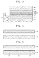
- FIG. 3 is a schematic cross-sectional view illustrating a back emission type flat panel display device including an EL device as the self-luminant device.
- the flat panel display device includes a substrate 12, a first electrode layer 14 formed on a first surface of the substrate 12, an interlayer 18 including a light emitting layer 182 formed on the first electrode layer 14, a second electrode layer 16 having a different polarity from that of the first electrode layer 14 on the interlayer 18, and a lens sheet 19 formed on a second surface of substrate 12.
- a sealing member 20 that seals the first electrode layer 14, the interlayer 18, and the second electrode layer 16 from the outside is located on the second electrode layer 16.
- a glass substrate made of SiO 2 can be used as the substrate 12.
- the substrate 12 may further include a buffer layer for planarizing the substrate and preventing infiltration of impurities, and the buffer layer can be made of SiO 2 .
- the substrate 12 can be made of a plastic material, as well as the glass material, and can be made of a polymer based flexible type material.
- the first electrode layer 14 that is stacked on the substrate 12 can be made of a transparent conductive material, for example, an indium-tin-oxide (ITO), and can be formed to be a predetermined pattern by a photolithography method.
- the pattern of the first electrode layer 14 can be stripes, which are separated from each other with predetermined intervals, in a case of passive matrix (PM) type, or can be formed to correspond to the pixels in a case of active matrix (AM) type.
- a small film transistor (TFT) layer including at least one TFT can be further located between the first electrode layer 14 and the substrate 12, and the first electrode layer 14 is electrically connected to the TFT.
- the above described feature is applied to all embodiments of the present invention that will be described later.
- the first electrode layer 14 made of the ITO can function as an anode by being connected to an outer first electrode terminal (not illustrated).
- the second electrode layer 16 is placed over the first electrode layer 14.
- the second electrode layer 16 can be a reflective electrode in the case where the self-luminant device is a back emission EL device, made of aluminium/calcium, and can function as a cathode by being connected to an outer second electrode terminal (not illustrated).
- the second electrode layer 16 is PM type, it can be formed as stripes crossing the pattern of the first electrode layer 14, and in a case where the second electrode layer 16 is the AM type, it can be formed on an entire active area on which images are displayed.
- the first electrode layer 14 and the second electrode layer 16 can have opposite polarities.
- the interlayer 18 located between the first electrode layer 14 and the second electrode layer 16 includes the light emitting layer 182 that emits light by electric operations of the first and second electrode layers 14 and 16.
- the EL device can be classified into an organic EL device or an inorganic EL device according to the interlayer 18. If the EL device is an organic EL device, a low molecular organic material or a high molecular organic material can be used.
- the interlayer 18 can include a first interlayer 184 including a hole transport layer (HTL) and a hole injection layer (HIL) in the direction of the first electrode layer 14 from the light emitting layer 182, and a second interlayer 186 including an electron transport layer and an electron injection layer (EIL) in the direction of the second electrode layer 16 from the light emitting layer 182.
- the hole injection layer, the hole transport layer, the electron transport layer, and the electron injection layer can be formed in various structures, and other layers performing different functions can be formed.
- the organic material can be copper phthalocyanine (CuPc), N,N-di(naphthalene-1-yl)-N,N'-diphenyl-benzidine (NPB), or tris-8-hydroxyquinoline aluminum (Alq3).
- the interlayer 18 can have the light emitting layer 182 of various patterns so as to correspond to colors of the pixels, in a case where the device is a full-color organic EL device.
- the low molecular organic layer can be formed in a way that the organic material is heated and deposited in a vacuum atmosphere, and the light emitting layer 182 can be formed by depositing respective colors using a mask, on which slits of predetermined pattern are formed, so as to correspond to the pixels.
- the HTL in a case of the high molecular organic layer made of the high molecular organic material, the HTL can be formed as the first interlayer 184 in the direction of the first electrode layer 14 from the light emitting layer 182, and the second interlayer 186 can be omitted.
- the high molecular HTL can be formed on the first electrode layer 14 of the transparent substrate 12 by an inkjet printing method or a spin coating method using poly-(2,4)-ethylene-dihydroxy thiophene (PEDOT) or polyaniline (PANI).
- the high molecular organic light emitting layer can be made of PPV, soluble PPV, cyano-PPV, or polyfluorene, and can be formed in an inkjet printing method, a spin coating method, or a thermal transfer method using laser.
- the structures of the first and second interlayers 184 and 186 are not limited thereto, but can be formed in various forms.
- the light emitting layer 182 is made of emitting atoms, for example, metal sulphide such as ZnS, SrS, and CaS or alkaline-earth potassium sulphide such as GaGa 2 S 4 and SrGa 2 S 4 , and transition metal or alkaline-earth metal including Mn, Ce, Tb, Eu, Tm, Er, Pr, and Pb.
- the first and second interlayers 184 and 186 can be formed as insulating layers.
- a sealing member 20 is located on the second electrode layer 16, and the sealing member 20 can be a metal cap including a desiccant therein. Otherwise, a resin material for sealing can be applied on the second electrode layer 16 so as to prevent humidity from infiltrating.
- the sealing member 20 can be formed using the substrate.
- the self-luminant device is the EL device, and the light emitted from the light emitting layer 182 propagates toward the substrate 12 for the back emission type.
- the emission type is not limited thereto, and the device can be the front emission type or dual emission type, and the self-luminant device does not have to be an EL device.
- a lens sheet 19 having condensing lenses is formed on the second surface of the substrate 12, and the lens sheet 19 can be made of a glass material having SiO 2 or an epoxy based plastic material.
- the epoxy based plastic is used as the lens sheet 19, the refractive index thereof is similar to that of glass, which is the material of the substrate 12, and an epoxy based material is also used as an adhesive to attach the lens sheet 19 to the substrate 12, thus reducing the total reflection and improving the light coupling efficiency.
- a distance T 12 from the light emitting layer 182 to the exterior portion of the lens sheet 19 in the direction of propagation of the light is controlled, and it is desirable that the distance T 12 is controlled to be small enough so that the sharpness of the image is improved and the light coupling efficiency is increased when the distance T 12 is small.
- the distance T12 includes the thickness of the first interlayer 184 (T14), the thickness of the first electrode layer 14 (T16), the thickness of the substrate 12 (T18), and the thickness of the lens sheet 19 (T 19).
- the thicknesses of the first interlayer 184 and the first electrode layer 14 are 1 ⁇ m or less, and the thickness T18 of the substrate 12 is hundreds of ⁇ m, thus it is important to control the thickness T18 of the substrate 12.
- the thickness T18 of the substrate 12 can be controlled to be small by etching the substrate 12.
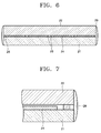
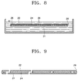
- FIGS. 4 through 9 are cross-sectional views illustrating the method of manufacturing the flat panel display device having small substrate.
- an upper substrate 21 and a lower substrate 22, which have relatively large thickness to prevent the pattern from being distorted when an image is formed by an image displaying unit, are positioned.
- the upper and the lower substrates 21 and 22 are made of a glass material that can be etched, however, the substrates 21 and 22 can be made of other materials that can be chemically or physically etched and have insulating characteristics.
- image display units 24 are formed at least on one surface between the facing surfaces as illustrated in FIG. 5 .
- the image display units 24 are separated from each other at predetermined intervals so as to construct a single image display apparatus when they are separated, and can be formed on the facing surfaces of the upper and lower substrates 21 and 22 that face each other.
- the upper and lower substrates 21 and 22 are sealed together as illustrated in FIG. 6 .
- a first sealing material 26 is applied along the edges of the upper and lower substrates 21 and 22 facing each other, and a second sealing material 28 is applied around each image display unit 24 to define the image display units 24, then the upper and lower substrates 21 and 22 are aligned to be sealed with each other.
- the first sealing material 26, formed on the edges of the upper and lower substrates 21 and 22, is applied on the outermost portions of the upper and lower substrates 21 and 22 to seal the substrates 21 and 22 together in order to protect the image display units 24 from an etchant.
- a protective layer 29 can be further formed on side portions of the upper and lower substrates 21 and 22 that are sealed by the first sealing material 26.
- the sealed upper and lower substrates 21 and 22 are etched to desired thicknesses.
- the etching of the upper and lower substrates 21 and 22 can be performed by a physical etching method or a chemical etching method as illustrated in FIG. 8 . Hydrofluoric acid or a hydrochloric acid can be used as the etchant in the chemical etching method.
- the thicknesses of the upper and lower substrates 21 and 22 can be different from each other at the initial stage to vary the thicknesses after performing the etching process. The thickness is preferably 100 ⁇ m or smaller.
- one image display unit can be formed on the substrates 21 and 22, the upper and lower substrates 21 and 22 are sealed as described above, and then etched.
- the sealed substrate is cut so that the cut portion includes one image display unit 24 as illustrated in FIG. 9 .
- the upper and lower substrates 21 and 22 can be cut by a thermal shock of a laser beam.
- the image display units are formed on the substrates, the upper and lower substrates 21 and 22 are sealed and etched to fabricate the small image display apparatus.
- the processes of manufacturing the small display apparatus can be simplified, and defects caused by the image display units formed on the substrate can be reduced.
- the flat panel display device that has the distance of at least 50 ⁇ m from the light emitting layer to the exterior portion of the condensing lens in the direction of propagation of the light can be manufactured without lowering the yield greatly.
- the images can be illustrated clearly until when the distance from the emitting layer to the exterior portion of the condensing lens is about 500 ⁇ m, however, if the distance is larger than 500 ⁇ m, the image sharpness deteriorates and the light coupling efficiency and the brightness are little improved over when the lens sheet is not applied to the device. Therefore, it is desirable that the distance is in a range of 50 ⁇ m to 500 ⁇ m.
- FIGS. 10 and 11 are cross-sectional views illustrating the flat panel display devices using front emission type and dual emission type EL devices, respectively. If the distances T 12 and T20 from the light emitting layer to the exterior portion of the condensing lens are set to be in the range of 50 ⁇ m ⁇ 500 ⁇ m, the light coupling efficiency and the brightness can be improved and the sharpness of the image is not sacrificed by attaching the lens sheet.
- FIG. 12 is a cross-sectional view illustrating the flat panel display device wherein the flat panel display device is a self-luminant device that is an EL device having a lens sheet and a substrate 32 formed integrally with each other.
- the lens sheet and the substrates can be formed integrally with each other, the number of elements is reduced, and the process of manufacturing the device can be simplified.
- the distance T22 from the light emitting layer to the exterior portion of the condensing lens in the direction of propagation of the light can be set to be in the range of 50 ⁇ m ⁇ 500 ⁇ m in order to prevent the sharpness of the image from being sacrificed.
- the flat panel display device of front emission type or dual emission type, in which the lens sheet and the sealing substrate are formed integrally with each other, can also be manufactured.
- FIG. 13 is a cross-sectional view illustrating a flat panel display device according to an embodiment of the present invention.
- the flat panel display device is a self-luminant device of a front emission type organic EL device and the lens sheet 19 is formed between the light emitting layer 182 and a sealing substrate 39.
- the organic EL device has a disadvantage of being prone to degradation by exposure to internal elements such as oxygen from the ITO and reaction between light emitting layer and the interlayer and exterior elements such as humidity, oxygen, ultraviolet rays, and fabricating conditions. Especially, the exterior oxygen and humidity severely affect the life span of the device, thus it is important to package the organic EL device well. Therefore, a protective layer 36 can be formed on the second electrode layer 16 of the organic EL device by depositing organic materials. Referring to FIG. 13 , the lens sheet 19 is located between the protective layer 36 and the sealing substrate 39. An epoxy based organic material or an acryl based organic material that is used to form the protective layer 36 can be used as an adhesive.
- a medium layer 38 between the lens sheet 19 and the sealing substrate 39 should have a lower refractive index than that of the lens sheet 19 as the condensing lens is a convex lens illustrated in FIG. 13 .
- the distance T32 from the light emitting layer to the exterior portion of the condensing lens in the direction of propagation of the light is set to be in the range of 50 ⁇ m ⁇ 500 ⁇ m, the light coupling efficiency and the brightness can be improved while the sharpness of the image is not sacrificed.
- the lens sheet can be located between the first electrode layer and the substrate. The above principles can also be applied to a dual emission type.
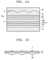
- FIG. 14 is a cross-sectional view illustrating a flat panel display device wherein the flat panel display is a self-luminant device that is a front emission type organic EL device, and the lens sheet 19 is formed between the light emitting layer 182 and a sealing substrate 49, and condensing lenses are formed in the sealing substrate 49.
- the refractive index of the sealing substrate 49 should be smaller than that of the lens sheet 19 material when the condensing lens is the convex lens as illustrated in FIG. 14 .
- the distance T42 from the light emitting layer to the exterior portion of the condensing lens in the direction of propagation of the light is set to be in a range of 50 ⁇ m ⁇ 500 ⁇ m, the light coupling efficiency and the brightness can be improved while the sharpness of the image is not sacrificed.
- the lens sheet can be located between the first electrode layer and the substrate, and the condensing lens of the lens sheet can be formed in the substrate, and the above structure can be also applied to the dual emission type device.
- FIG. 15 is a cross-sectional view illustrating a flat panel display device where the self-luminant devices 1 are arranged on one side of the substrate 2 and the condensing lenses 52 are arranged on the other side of the substrate 2.
- the flat panel display device has condensing lenses 52 that correspond one-to-one with the self-luminant devices 1.
- one condensing lens 52 only corresponds to one self-luminant device 1, and a center of the condensing lens 52 and a center of the self-luminant device 1 are lined up with each other.
- the condensing lenses 52 correspond one-to-one with the self-luminant devices 1, the light of the self-luminant devices 1 can be condensed by the condensing lenses 52 more efficiently.
- the condensing is a convex lens. If the convex lens is used, the light coupling efficiency and the brightness can be improved more than the case of when concave lenses are used, and the sharpness is sacrificed less than in the case where the prism is used.
- the condensing lens having a plurality of focuses is used since the EL device is a surface source, not a point source.
- the condensing lens having a plurality of focuses is used, the light coupling efficiency and the brightness at the front side can be improved more than when the condensing lens having one focus are used.
- FIG. 16 is a graph illustrating results of measuring brightness versus a range of viewing angles from left/right directions based on the front side when the lens sheet is attached and is not attached, and a unit of the brightness is cd/m 2 .
- reference example (ref.) is the result measured in a case where the lens sheet is not attached to the substrate, and the embodiments are the measurements when curvatures of the condensing lenses are 30 ⁇ m, 40 ⁇ m, and 60 ⁇ m, respectively.
- the condensing lens When the curvature of the condensing lens is 30 ⁇ m or 40 ⁇ m, one condensing lens corresponds to one sub-pixel, and when the curvature of the condensing lens is 60 ⁇ m, the condensing lens is formed in a stripe shape. As illustrated in FIG. 16 , the brightness measured when the lens sheet is attached to the substrate is 1.5 times brighter than that measured when the lens sheet is not attached to the substrate.
- FIG. 17 is a graph illustrating results of measuring power consumption when the brightness is 250cd/m 2 , in cases where the lens sheet is attached and is not attached.
- the unit of power consumption is mW.
- the power consumption when the lens sheet is attached to the substrate is about 66% of that when the lens sheet is not attached, thus the power consumption can be reduced and the life span of the self-luminant device can be increased by attaching the lens sheet.
- the distance from the light emitting layer to the exterior portion of the condensing lens in the direction of propagation of the light can be designed to fall within a predetermined range, resulting in improved sharpness of the image that passes through the lens sheet.
- the lens sheet is formed on the substrate or on the sealing substrate to reduce the total reflection of light due to the self-luminant device, and to direct the light in a predetermined direction, thus increasing the light coupling efficiency and the brightness. Accordingly, the power consumption of the device can be reduced, and the life span of the self-luminant device can be increased. If the lens sheet and the substrate or the sealing substrate are formed integrally with each other, the number of elements is reduced and processes of manufacturing the device can be simplified. Also, since the lens sheet is formed between the self-luminant device and the substrate or the sealing substrate, the distance from the light emitting layer to the exterior portion of the condensing lens can be reduced.
- the lens sheet is formed between the self-luminant device and the substrate or the sealing substrate and the condensing lenses are formed in the substrate or the sealing substrate, the distance from the light emitting layer to the exterior portion of the lens sheet of the can be reduced and the structure of the flat panel display device can be simplified.
- light coupling efficiency can be further improved by forming a one-to-one correspondence between the self-luminant devices and the lenses.
- the convex lens is used as the condensing lens, the light coupling efficiency and the brightness can be improved while the sharpness of the image is not sacrificed.
Landscapes
- Physics & Mathematics (AREA)
- Optics & Photonics (AREA)
- Electroluminescent Light Sources (AREA)
- Devices For Indicating Variable Information By Combining Individual Elements (AREA)
Applications Claiming Priority (2)
| Application Number | Priority Date | Filing Date | Title |
|---|---|---|---|
| KR1020040026644A KR100730114B1 (ko) | 2004-04-19 | 2004-04-19 | 평판표시장치 |
| KR2004026644 | 2004-04-19 |
Publications (3)
| Publication Number | Publication Date |
|---|---|
| EP1589584A2 EP1589584A2 (en) | 2005-10-26 |
| EP1589584A3 EP1589584A3 (en) | 2005-11-23 |
| EP1589584B1 true EP1589584B1 (en) | 2016-10-19 |
Family
ID=34939355
Family Applications (1)
| Application Number | Title | Priority Date | Filing Date |
|---|---|---|---|
| EP05103083.1A Active EP1589584B1 (en) | 2004-04-19 | 2005-04-18 | Flat panel display device |
Country Status (5)
| Country | Link |
|---|---|
| US (1) | US7733019B2 (ko) |
| EP (1) | EP1589584B1 (ko) |
| JP (2) | JP2005310749A (ko) |
| KR (1) | KR100730114B1 (ko) |
| CN (2) | CN103813562A (ko) |
Families Citing this family (55)
| Publication number | Priority date | Publication date | Assignee | Title |
|---|---|---|---|---|
| GB2400483B (en) * | 2003-04-09 | 2006-04-12 | One2See Ltd | Segmented electroluminescent panel |
| GB0514554D0 (en) | 2005-07-15 | 2005-08-24 | Materialise Nv | Method for (semi-) automatic dental implant planning |
| KR100683791B1 (ko) * | 2005-07-30 | 2007-02-20 | 삼성에스디아이 주식회사 | 박막 트랜지스터 기판 및 이를 구비한 평판 디스플레이장치 |
| JP4464370B2 (ja) * | 2006-06-07 | 2010-05-19 | 株式会社日立製作所 | 照明装置及び表示装置 |
| JP2008003466A (ja) * | 2006-06-26 | 2008-01-10 | Mitsutoyo Corp | レンズ光学系及び光電式エンコーダ |
| EP1890315A3 (en) * | 2006-08-18 | 2009-07-01 | LG Electronics Inc. | Filter and plasma display device thereof |
| KR100805154B1 (ko) * | 2006-09-15 | 2008-02-21 | 삼성에스디아이 주식회사 | 유기 발광 표시 장치 및 그 제조 방법 |
| WO2008043035A2 (en) * | 2006-10-04 | 2008-04-10 | Rochester Institute Of Technology | Aspect-ratio independent, multimedia presentation systems and methods thereof |
| FR2913814B1 (fr) * | 2007-03-13 | 2009-07-31 | Saint Gobain | Lampe plane feuilletee et son procede de fabrication |
| KR100835059B1 (ko) * | 2007-07-06 | 2008-06-03 | 삼성전자주식회사 | 양자점 광소자 |
| JP2009049135A (ja) | 2007-08-17 | 2009-03-05 | Sony Corp | 表示装置 |
| DE102007058453A1 (de) * | 2007-09-10 | 2009-03-12 | Osram Opto Semiconductors Gmbh | Strahlungsemittierende Vorrichtung |
| EP2091096A1 (en) * | 2008-02-15 | 2009-08-19 | Nederlandse Organisatie voor toegepast-natuurwetenschappelijk Onderzoek TNO | Encapsulated electronic device and method of manufacturing |
| KR101115154B1 (ko) * | 2008-05-23 | 2012-02-24 | 주식회사 엘지화학 | 유기 발광 소자 및 이의 제조방법 |
| KR101493021B1 (ko) * | 2008-08-19 | 2015-02-12 | 삼성디스플레이 주식회사 | 유기 발광 표시 장치 |
| JP5287355B2 (ja) * | 2009-03-02 | 2013-09-11 | 凸版印刷株式会社 | El素子、並びにそれを用いた液晶ディスプレイ用バックライト装置、電子看板装置、照明装置、ディスプレイ装置、及び光取り出しフィルム |
| KR101182673B1 (ko) * | 2009-05-13 | 2012-09-14 | 네오뷰코오롱 주식회사 | 유기전계발광소자 및 그 제조방법 |
| JP4947095B2 (ja) * | 2009-06-16 | 2012-06-06 | 住友化学株式会社 | 光取り出し構造体 |
| JP2011029172A (ja) * | 2009-06-30 | 2011-02-10 | Fujifilm Corp | 有機el装置及びその設計方法 |
| EP2449592B1 (en) * | 2009-07-01 | 2019-08-07 | Beijing Xiaomi Mobile Software Co., Ltd. | Light emitting device based on oleds |
| JPWO2011016126A1 (ja) * | 2009-08-06 | 2013-01-10 | キヤノン株式会社 | 表示装置 |
| JP5480567B2 (ja) * | 2009-09-01 | 2014-04-23 | パナソニック株式会社 | 有機発光素子 |
| JP2010034074A (ja) * | 2009-11-09 | 2010-02-12 | Sony Corp | 表示装置 |
| KR101296684B1 (ko) * | 2009-11-18 | 2013-08-19 | 한국전자통신연구원 | 상 분리 현상을 이용한 유기 발광 다이오드 및 그 제조 방법 |
| KR20110106733A (ko) | 2010-03-23 | 2011-09-29 | 삼성모바일디스플레이주식회사 | 유기 발광 표시 장치 |
| WO2011121662A1 (ja) * | 2010-03-31 | 2011-10-06 | パナソニック株式会社 | 表示パネル装置及び表示パネル装置の製造方法 |
| CN102293053B (zh) * | 2010-03-31 | 2015-04-15 | 松下电器产业株式会社 | 显示面板装置以及显示面板装置的制造方法 |
| KR101676313B1 (ko) | 2010-05-31 | 2016-11-16 | 삼성디스플레이 주식회사 | 유기 발광 장치 |
| JP2012059692A (ja) * | 2010-08-09 | 2012-03-22 | Canon Inc | 有機エレクトロルミネッセンス表示装置 |
| KR101248904B1 (ko) * | 2010-10-18 | 2013-03-28 | 한국과학기술원 | 유기 발광 소자, 유기 발광 소자를 포함하는 조명 장치, 및 유기 발광 소자를 포함하는 디스플레이 장치 |
| JP2012178332A (ja) * | 2011-02-04 | 2012-09-13 | Canon Inc | 表示装置 |
| KR101880184B1 (ko) * | 2011-02-14 | 2018-07-19 | 가부시키가이샤 한도오따이 에네루기 켄큐쇼 | 발광장치 |
| CN102683608B (zh) * | 2011-03-14 | 2015-04-29 | 海洋王照明科技股份有限公司 | 一种有机电致发光器件及其制备方法 |
| EP2506332A1 (en) * | 2011-03-31 | 2012-10-03 | Moser Baer India Ltd. | Substrate for improved handling and protection of an optoelectronic device |
| JP2012227122A (ja) * | 2011-04-04 | 2012-11-15 | Rohm Co Ltd | 有機el装置 |
| JP2013077412A (ja) * | 2011-09-30 | 2013-04-25 | Toppan Printing Co Ltd | El素子及びこれを用いた照明装置、ディスプレイ装置、液晶ディスプレイ装置 |
| FR2991101B1 (fr) * | 2012-05-25 | 2016-05-06 | Saint Gobain | Dispositif a diode electroluminescente organique comportant un support comprenant un element en couches transparent |
| CN103959504B (zh) * | 2012-05-31 | 2016-11-02 | 乐金显示有限公司 | 有机发光器件及其制备方法 |
| WO2014069565A1 (ja) * | 2012-10-31 | 2014-05-08 | 昭和電工株式会社 | 有機el素子並びにそれを備えた画像表示装置及び照明装置 |
| CN105940519A (zh) * | 2013-11-27 | 2016-09-14 | 娜我比可隆股份有限公司 | 用于制造基板的方法、基板、用于制造有机电致发光器件的方法和有机电致发光器件 |
| EP3089550A4 (en) * | 2013-12-27 | 2017-09-06 | JX Nippon Oil & Energy Corporation | Light-emitting element |
| KR102189819B1 (ko) * | 2014-09-01 | 2020-12-14 | 삼성디스플레이 주식회사 | 유기 발광 표시 장치 |
| CN104900683A (zh) | 2015-06-10 | 2015-09-09 | 京东方科技集团股份有限公司 | 一种显示基板及其制备方法、显示装置 |
| US10686159B2 (en) * | 2015-06-26 | 2020-06-16 | Universal Display Corporation | OLED devices having improved efficiency |
| CN106129260B (zh) * | 2016-06-30 | 2019-03-19 | 京东方科技集团股份有限公司 | 一种显示面板及显示装置 |
| CN106410059A (zh) * | 2016-09-19 | 2017-02-15 | 张家港康得新光电材料有限公司 | 一种取出膜的结构与制备方法及其应用 |
| CN114335382A (zh) | 2018-12-07 | 2022-04-12 | 京东方科技集团股份有限公司 | 显示模组及其制备方法 |
| CN109817843B (zh) * | 2019-01-30 | 2021-10-08 | 武汉华星光电半导体显示技术有限公司 | 在oled显示器中形成微透镜阵列的方法和微透镜阵列 |
| JP7006654B2 (ja) * | 2019-05-09 | 2022-01-24 | セイコーエプソン株式会社 | 表示装置、および電子機器 |
| JP7151616B2 (ja) | 2019-05-09 | 2022-10-12 | セイコーエプソン株式会社 | 表示装置、および電子機器 |
| JP7006653B2 (ja) * | 2019-05-09 | 2022-01-24 | セイコーエプソン株式会社 | 表示装置、および電子機器 |
| CN111129352B (zh) * | 2020-01-02 | 2022-04-12 | 京东方科技集团股份有限公司 | 一种oled显示面板及显示装置 |
| CN111613734B (zh) * | 2020-05-29 | 2023-04-07 | 武汉天马微电子有限公司 | 光取出层及其制作方法、显示面板 |
| CN111816787A (zh) * | 2020-06-30 | 2020-10-23 | 合肥维信诺科技有限公司 | 一种显示面板和显示装置 |
| CN112885979A (zh) * | 2021-02-01 | 2021-06-01 | 合肥京东方卓印科技有限公司 | 一种显示面板及其制备方法、以及显示装置 |
Citations (1)
| Publication number | Priority date | Publication date | Assignee | Title |
|---|---|---|---|---|
| US20040051447A1 (en) * | 2002-09-12 | 2004-03-18 | Canon Kabushiki Kaisha | Organic electroluminescent display and apparatus including organic electroluminescent display |
Family Cites Families (33)
| Publication number | Priority date | Publication date | Assignee | Title |
|---|---|---|---|---|
| JPH0471189A (ja) * | 1990-07-10 | 1992-03-05 | Fukuvi Chem Ind Co Ltd | エレクトロルミネッセンスおよびその製造方法 |
| JPH04192290A (ja) | 1990-11-26 | 1992-07-10 | Sharp Corp | 薄膜el装置 |
| JP3065458B2 (ja) | 1993-07-20 | 2000-07-17 | シャープ株式会社 | El素子 |
| JP3420399B2 (ja) * | 1995-07-28 | 2003-06-23 | キヤノン株式会社 | 発光素子 |
| DE19623881A1 (de) | 1996-06-05 | 1997-12-11 | Hertz Inst Heinrich | Elektrolumineszenzdisplay |
| JP4073510B2 (ja) * | 1996-12-13 | 2008-04-09 | 出光興産株式会社 | 有機el発光装置 |
| JPH10223367A (ja) * | 1997-02-04 | 1998-08-21 | Mitsubishi Chem Corp | 有機電界発光素子 |
| JPH1174072A (ja) * | 1997-08-29 | 1999-03-16 | Sharp Corp | 薄膜elパネル及びその製造方法 |
| JPH11344602A (ja) * | 1998-03-30 | 1999-12-14 | Seiko Epson Corp | ブラックマトリクス付マイクロレンズ基板の製造方法、液晶パネル用対向基板、液晶パネルおよび投射型表示装置 |
| JP4143181B2 (ja) * | 1998-08-31 | 2008-09-03 | キヤノン株式会社 | 露光装置及び画像形成装置 |
| JP2000206894A (ja) * | 1998-11-10 | 2000-07-28 | Toshiba Corp | 平面表示装置 |
| JP3613065B2 (ja) | 1999-03-30 | 2005-01-26 | 凸版印刷株式会社 | 液晶表示装置 |
| JP2001013489A (ja) * | 1999-06-30 | 2001-01-19 | Toshiba Corp | 液晶表示装置の製造方法 |
| KR100700993B1 (ko) * | 1999-12-03 | 2007-03-30 | 크리, 인코포레이티드 | 향상된 광 적출 구조체를 갖는 발광 다이오드 및 그 제조 방법 |
| JP4524843B2 (ja) * | 2000-03-16 | 2010-08-18 | ソニー株式会社 | 直視型表示装置 |
| US6345903B1 (en) * | 2000-09-01 | 2002-02-12 | Citizen Electronics Co., Ltd. | Surface-mount type emitting diode and method of manufacturing same |
| JP2002182008A (ja) * | 2000-10-04 | 2002-06-26 | Sharp Corp | 光学レンズシステム、画像表示装置、マイクロレンズアレイ、液晶表示素子および投影型液晶表示装置 |
| US6809470B2 (en) * | 2000-12-29 | 2004-10-26 | Intel Corporation | Flat panel color display with enhanced brightness and preferential viewing angles |
| JP2002260845A (ja) * | 2001-03-02 | 2002-09-13 | Matsushita Electric Ind Co Ltd | 有機エレクトロルミネッセンス発光素子、それを用いた表示装置または発光源 |
| JP2002318545A (ja) * | 2001-04-20 | 2002-10-31 | Sony Corp | 表示パネルの製造方法及び製造装置 |
| JP4750969B2 (ja) * | 2001-06-27 | 2011-08-17 | 東芝モバイルディスプレイ株式会社 | 平面表示装置の製造方法 |
| JP2003031353A (ja) | 2001-07-10 | 2003-01-31 | Matsushita Electric Ind Co Ltd | 発光素子およびその製造方法ならびにそれを用いた表示パネル |
| JP2003036974A (ja) * | 2001-07-23 | 2003-02-07 | Victor Co Of Japan Ltd | 有機エレクトロルミネッセンス素子及びその製造方法 |
| TW522751B (en) * | 2001-12-31 | 2003-03-01 | Ritdisplay Corp | Organic flat light emitting device |
| JP4239499B2 (ja) * | 2002-07-12 | 2009-03-18 | パナソニック株式会社 | 有機エレクトロルミネッセンス素子、それを用いた画像形成装置、携帯端末、有機エレクトロルミネッセンス素子の製造方法 |
| JP2003260812A (ja) * | 2002-03-11 | 2003-09-16 | Seiko Epson Corp | 光印写ヘッド及びそれを用いた画像形成装置 |
| JP2003291406A (ja) * | 2002-04-02 | 2003-10-14 | Seiko Epson Corp | 有機elアレイ露光ヘッド及びそれを用いた画像形成装置 |
| JP4438312B2 (ja) * | 2002-05-21 | 2010-03-24 | セイコーエプソン株式会社 | 電気光学装置及び電子機器 |
| JP2004039500A (ja) * | 2002-07-04 | 2004-02-05 | Seiko Epson Corp | 有機エレクトロルミネッセンス装置、有機エレクトロルミネッセンス装置の製造方法及び電子機器 |
| JP2004058448A (ja) * | 2002-07-29 | 2004-02-26 | Denso Corp | 光プリンタヘッド |
| JP2004071246A (ja) * | 2002-08-02 | 2004-03-04 | Harison Toshiba Lighting Corp | 両面発光表示装置 |
| JP2004127662A (ja) * | 2002-10-01 | 2004-04-22 | Sony Corp | 表示装置 |
| TWI223219B (en) * | 2003-10-17 | 2004-11-01 | Delta Optoelectronics Inc | Organic electroluminance display panel package and manufacturing method thereof |
-
2004
- 2004-04-19 KR KR1020040026644A patent/KR100730114B1/ko active IP Right Grant
-
2005
- 2005-01-27 JP JP2005020337A patent/JP2005310749A/ja not_active Withdrawn
- 2005-04-01 US US11/095,621 patent/US7733019B2/en active Active
- 2005-04-18 EP EP05103083.1A patent/EP1589584B1/en active Active
- 2005-04-19 CN CN201410082062.1A patent/CN103813562A/zh active Pending
- 2005-04-19 CN CNA2005100672067A patent/CN1691857A/zh active Pending
-
2011
- 2011-07-01 JP JP2011147656A patent/JP2011216492A/ja active Pending
Patent Citations (1)
| Publication number | Priority date | Publication date | Assignee | Title |
|---|---|---|---|---|
| US20040051447A1 (en) * | 2002-09-12 | 2004-03-18 | Canon Kabushiki Kaisha | Organic electroluminescent display and apparatus including organic electroluminescent display |
Also Published As
| Publication number | Publication date |
|---|---|
| JP2005310749A (ja) | 2005-11-04 |
| US7733019B2 (en) | 2010-06-08 |
| EP1589584A3 (en) | 2005-11-23 |
| JP2011216492A (ja) | 2011-10-27 |
| EP1589584A2 (en) | 2005-10-26 |
| US20050231085A1 (en) | 2005-10-20 |
| CN103813562A (zh) | 2014-05-21 |
| KR20050101425A (ko) | 2005-10-24 |
| KR100730114B1 (ko) | 2007-06-19 |
| CN1691857A (zh) | 2005-11-02 |
Similar Documents
| Publication | Publication Date | Title |
|---|---|---|
| EP1589584B1 (en) | Flat panel display device | |
| US7144752B2 (en) | Method of manufacturing organic electroluminescent display device and organic electroluminescent display device, and display device equipped with organic electroluminescent display device | |
| US9024302B2 (en) | Display device | |
| KR100515110B1 (ko) | 전기 광학 장치 및 전자 기기 | |
| US8552634B2 (en) | Organic light-emitting display apparatus | |
| JP4432863B2 (ja) | 有機エレクトロルミネッセンス装置及び電子機器 | |
| JP4431125B2 (ja) | 平板ディスプレイ装置及びその製造方法 | |
| KR101906508B1 (ko) | 유기 광전자 장치 및 그 봉입 방법 | |
| US20060192487A1 (en) | Display device and fabricating method thereof | |
| US9818973B2 (en) | Display device | |
| US20130001610A1 (en) | Display apparatus | |
| CN108987444B (zh) | 显示基板及其制作方法、显示面板和显示装置 | |
| EP2197061B1 (en) | Organic light emitting diode display | |
| KR100730113B1 (ko) | 평판표시장치 | |
| JP2013077460A (ja) | 有機elパネルの製造方法、有機elパネル及び有機elディスプレイ | |
| JP5987407B2 (ja) | 有機エレクトロルミネッセンスパネル | |
| JP2004152738A (ja) | 有機elパネルおよびその製造方法、それを用いた電気光学パネル並びに電子機器 | |
| CN111785767B (zh) | 镜面显示装置及其制作方法 | |
| US20130343063A1 (en) | Display device and method of manufacturing the same | |
| JP2007323814A (ja) | エリア発光型有機el表示パネルおよび階調制御方法 | |
| JP2019102299A (ja) | 有機el素子、並びに有機el照明装置、有機el素子光源及び有機el表示装置 | |
| KR100603344B1 (ko) | 평판 표시장치 | |
| KR20050111493A (ko) | 평판 표시 장치 및 그 제조방법 |
Legal Events
| Date | Code | Title | Description |
|---|---|---|---|
| PUAI | Public reference made under article 153(3) epc to a published international application that has entered the european phase |
Free format text: ORIGINAL CODE: 0009012 |
|
| PUAL | Search report despatched |
Free format text: ORIGINAL CODE: 0009013 |
|
| 17P | Request for examination filed |
Effective date: 20050512 |
|
| AK | Designated contracting states |
Kind code of ref document: A2 Designated state(s): AT BE BG CH CY CZ DE DK EE ES FI FR GB GR HU IE IS IT LI LT LU MC NL PL PT RO SE SI SK TR |
|
| AX | Request for extension of the european patent |
Extension state: AL BA HR LV MK YU |
|
| AK | Designated contracting states |
Kind code of ref document: A3 Designated state(s): AT BE BG CH CY CZ DE DK EE ES FI FR GB GR HU IE IS IT LI LT LU MC NL PL PT RO SE SI SK TR |
|
| AX | Request for extension of the european patent |
Extension state: AL BA HR LV MK YU |
|
| AKX | Designation fees paid |
Designated state(s): AT BE BG CH CY CZ DE DK EE ES FI FR GB GR HU IE IS IT LI LT LU MC NL PL PT RO SE SI SK TR |
|
| 17Q | First examination report despatched |
Effective date: 20080417 |
|
| RAP1 | Party data changed (applicant data changed or rights of an application transferred) |
Owner name: SAMSUNG MOBILE DISPLAY CO., LTD. |
|
| RAP1 | Party data changed (applicant data changed or rights of an application transferred) |
Owner name: SAMSUNG DISPLAY CO., LTD. |
|
| RAP1 | Party data changed (applicant data changed or rights of an application transferred) |
Owner name: SAMSUNG DISPLAY CO., LTD. |
|
| REG | Reference to a national code |
Ref country code: DE Ref legal event code: R079 Ref document number: 602005050457 Country of ref document: DE Free format text: PREVIOUS MAIN CLASS: H01L0027150000 Ipc: H01L0027320000 |
|
| GRAP | Despatch of communication of intention to grant a patent |
Free format text: ORIGINAL CODE: EPIDOSNIGR1 |
|
| RIC1 | Information provided on ipc code assigned before grant |
Ipc: H01L 27/32 20060101AFI20160414BHEP Ipc: H01L 51/52 20060101ALI20160414BHEP |
|
| INTG | Intention to grant announced |
Effective date: 20160511 |
|
| RIN1 | Information on inventor provided before grant (corrected) |
Inventor name: CHOI, DONG-SOO Inventor name: SONG, SEUNG-YONG Inventor name: LEE, MIN-GYU Inventor name: PARK, JIN-WOO Inventor name: KWON, JANG-HYUK |
|
| GRAS | Grant fee paid |
Free format text: ORIGINAL CODE: EPIDOSNIGR3 |
|
| GRAA | (expected) grant |
Free format text: ORIGINAL CODE: 0009210 |
|
| AK | Designated contracting states |
Kind code of ref document: B1 Designated state(s): AT BE BG CH CY CZ DE DK EE ES FI FR GB GR HU IE IS IT LI LT LU MC NL PL PT RO SE SI SK TR |
|
| REG | Reference to a national code |
Ref country code: GB Ref legal event code: FG4D |
|
| REG | Reference to a national code |
Ref country code: CH Ref legal event code: EP |
|
| REG | Reference to a national code |
Ref country code: AT Ref legal event code: REF Ref document number: 838985 Country of ref document: AT Kind code of ref document: T Effective date: 20161115 |
|
| REG | Reference to a national code |
Ref country code: IE Ref legal event code: FG4D |
|
| REG | Reference to a national code |
Ref country code: DE Ref legal event code: R096 Ref document number: 602005050457 Country of ref document: DE |
|
| REG | Reference to a national code |
Ref country code: NL Ref legal event code: MP Effective date: 20161019 |
|
| REG | Reference to a national code |
Ref country code: LT Ref legal event code: MG4D |
|
| REG | Reference to a national code |
Ref country code: AT Ref legal event code: MK05 Ref document number: 838985 Country of ref document: AT Kind code of ref document: T Effective date: 20161019 |
|
| REG | Reference to a national code |
Ref country code: FR Ref legal event code: PLFP Year of fee payment: 13 |
|
| PG25 | Lapsed in a contracting state [announced via postgrant information from national office to epo] |
Ref country code: GR Free format text: LAPSE BECAUSE OF FAILURE TO SUBMIT A TRANSLATION OF THE DESCRIPTION OR TO PAY THE FEE WITHIN THE PRESCRIBED TIME-LIMIT Effective date: 20170120 Ref country code: LT Free format text: LAPSE BECAUSE OF FAILURE TO SUBMIT A TRANSLATION OF THE DESCRIPTION OR TO PAY THE FEE WITHIN THE PRESCRIBED TIME-LIMIT Effective date: 20161019 Ref country code: SE Free format text: LAPSE BECAUSE OF FAILURE TO SUBMIT A TRANSLATION OF THE DESCRIPTION OR TO PAY THE FEE WITHIN THE PRESCRIBED TIME-LIMIT Effective date: 20161019 |
|
| PG25 | Lapsed in a contracting state [announced via postgrant information from national office to epo] |
Ref country code: BE Free format text: LAPSE BECAUSE OF FAILURE TO SUBMIT A TRANSLATION OF THE DESCRIPTION OR TO PAY THE FEE WITHIN THE PRESCRIBED TIME-LIMIT Effective date: 20161019 Ref country code: NL Free format text: LAPSE BECAUSE OF FAILURE TO SUBMIT A TRANSLATION OF THE DESCRIPTION OR TO PAY THE FEE WITHIN THE PRESCRIBED TIME-LIMIT Effective date: 20161019 Ref country code: IS Free format text: LAPSE BECAUSE OF FAILURE TO SUBMIT A TRANSLATION OF THE DESCRIPTION OR TO PAY THE FEE WITHIN THE PRESCRIBED TIME-LIMIT Effective date: 20170219 Ref country code: ES Free format text: LAPSE BECAUSE OF FAILURE TO SUBMIT A TRANSLATION OF THE DESCRIPTION OR TO PAY THE FEE WITHIN THE PRESCRIBED TIME-LIMIT Effective date: 20161019 Ref country code: PL Free format text: LAPSE BECAUSE OF FAILURE TO SUBMIT A TRANSLATION OF THE DESCRIPTION OR TO PAY THE FEE WITHIN THE PRESCRIBED TIME-LIMIT Effective date: 20161019 Ref country code: FI Free format text: LAPSE BECAUSE OF FAILURE TO SUBMIT A TRANSLATION OF THE DESCRIPTION OR TO PAY THE FEE WITHIN THE PRESCRIBED TIME-LIMIT Effective date: 20161019 Ref country code: PT Free format text: LAPSE BECAUSE OF FAILURE TO SUBMIT A TRANSLATION OF THE DESCRIPTION OR TO PAY THE FEE WITHIN THE PRESCRIBED TIME-LIMIT Effective date: 20170220 Ref country code: AT Free format text: LAPSE BECAUSE OF FAILURE TO SUBMIT A TRANSLATION OF THE DESCRIPTION OR TO PAY THE FEE WITHIN THE PRESCRIBED TIME-LIMIT Effective date: 20161019 |
|
| REG | Reference to a national code |
Ref country code: DE Ref legal event code: R097 Ref document number: 602005050457 Country of ref document: DE |
|
| PG25 | Lapsed in a contracting state [announced via postgrant information from national office to epo] |
Ref country code: CZ Free format text: LAPSE BECAUSE OF FAILURE TO SUBMIT A TRANSLATION OF THE DESCRIPTION OR TO PAY THE FEE WITHIN THE PRESCRIBED TIME-LIMIT Effective date: 20161019 Ref country code: SK Free format text: LAPSE BECAUSE OF FAILURE TO SUBMIT A TRANSLATION OF THE DESCRIPTION OR TO PAY THE FEE WITHIN THE PRESCRIBED TIME-LIMIT Effective date: 20161019 Ref country code: DK Free format text: LAPSE BECAUSE OF FAILURE TO SUBMIT A TRANSLATION OF THE DESCRIPTION OR TO PAY THE FEE WITHIN THE PRESCRIBED TIME-LIMIT Effective date: 20161019 Ref country code: RO Free format text: LAPSE BECAUSE OF FAILURE TO SUBMIT A TRANSLATION OF THE DESCRIPTION OR TO PAY THE FEE WITHIN THE PRESCRIBED TIME-LIMIT Effective date: 20161019 Ref country code: EE Free format text: LAPSE BECAUSE OF FAILURE TO SUBMIT A TRANSLATION OF THE DESCRIPTION OR TO PAY THE FEE WITHIN THE PRESCRIBED TIME-LIMIT Effective date: 20161019 |
|
| PLBE | No opposition filed within time limit |
Free format text: ORIGINAL CODE: 0009261 |
|
| STAA | Information on the status of an ep patent application or granted ep patent |
Free format text: STATUS: NO OPPOSITION FILED WITHIN TIME LIMIT |
|
| PG25 | Lapsed in a contracting state [announced via postgrant information from national office to epo] |
Ref country code: IT Free format text: LAPSE BECAUSE OF FAILURE TO SUBMIT A TRANSLATION OF THE DESCRIPTION OR TO PAY THE FEE WITHIN THE PRESCRIBED TIME-LIMIT Effective date: 20161019 Ref country code: BG Free format text: LAPSE BECAUSE OF FAILURE TO SUBMIT A TRANSLATION OF THE DESCRIPTION OR TO PAY THE FEE WITHIN THE PRESCRIBED TIME-LIMIT Effective date: 20170119 |
|
| 26N | No opposition filed |
Effective date: 20170720 |
|
| PG25 | Lapsed in a contracting state [announced via postgrant information from national office to epo] |
Ref country code: SI Free format text: LAPSE BECAUSE OF FAILURE TO SUBMIT A TRANSLATION OF THE DESCRIPTION OR TO PAY THE FEE WITHIN THE PRESCRIBED TIME-LIMIT Effective date: 20161019 |
|
| REG | Reference to a national code |
Ref country code: CH Ref legal event code: PL |
|
| REG | Reference to a national code |
Ref country code: IE Ref legal event code: MM4A |
|
| PG25 | Lapsed in a contracting state [announced via postgrant information from national office to epo] |
Ref country code: MC Free format text: LAPSE BECAUSE OF FAILURE TO SUBMIT A TRANSLATION OF THE DESCRIPTION OR TO PAY THE FEE WITHIN THE PRESCRIBED TIME-LIMIT Effective date: 20161019 |
|
| PG25 | Lapsed in a contracting state [announced via postgrant information from national office to epo] |
Ref country code: CH Free format text: LAPSE BECAUSE OF NON-PAYMENT OF DUE FEES Effective date: 20170430 Ref country code: LU Free format text: LAPSE BECAUSE OF NON-PAYMENT OF DUE FEES Effective date: 20170418 Ref country code: LI Free format text: LAPSE BECAUSE OF NON-PAYMENT OF DUE FEES Effective date: 20170430 |
|
| REG | Reference to a national code |
Ref country code: FR Ref legal event code: PLFP Year of fee payment: 14 |
|
| PG25 | Lapsed in a contracting state [announced via postgrant information from national office to epo] |
Ref country code: IE Free format text: LAPSE BECAUSE OF NON-PAYMENT OF DUE FEES Effective date: 20170418 |
|
| PG25 | Lapsed in a contracting state [announced via postgrant information from national office to epo] |
Ref country code: HU Free format text: LAPSE BECAUSE OF FAILURE TO SUBMIT A TRANSLATION OF THE DESCRIPTION OR TO PAY THE FEE WITHIN THE PRESCRIBED TIME-LIMIT; INVALID AB INITIO Effective date: 20050418 |
|
| PG25 | Lapsed in a contracting state [announced via postgrant information from national office to epo] |
Ref country code: CY Free format text: LAPSE BECAUSE OF NON-PAYMENT OF DUE FEES Effective date: 20161019 |
|
| PG25 | Lapsed in a contracting state [announced via postgrant information from national office to epo] |
Ref country code: TR Free format text: LAPSE BECAUSE OF FAILURE TO SUBMIT A TRANSLATION OF THE DESCRIPTION OR TO PAY THE FEE WITHIN THE PRESCRIBED TIME-LIMIT Effective date: 20161019 |
|
| REG | Reference to a national code |
Ref country code: DE Ref legal event code: R079 Ref document number: 602005050457 Country of ref document: DE Free format text: PREVIOUS MAIN CLASS: H01L0027320000 Ipc: H10K0059000000 |
|
| PGFP | Annual fee paid to national office [announced via postgrant information from national office to epo] |
Ref country code: FR Payment date: 20230321 Year of fee payment: 19 |
|
| P01 | Opt-out of the competence of the unified patent court (upc) registered |
Effective date: 20230515 |
|
| PGFP | Annual fee paid to national office [announced via postgrant information from national office to epo] |
Ref country code: DE Payment date: 20230320 Year of fee payment: 19 |
|
| PGFP | Annual fee paid to national office [announced via postgrant information from national office to epo] |
Ref country code: GB Payment date: 20240320 Year of fee payment: 20 |