EP1588922A2 - Système et procédé de contrôle pour véhicule autodirecteur - Google Patents
Système et procédé de contrôle pour véhicule autodirecteur Download PDFInfo
- Publication number
- EP1588922A2 EP1588922A2 EP05252452A EP05252452A EP1588922A2 EP 1588922 A2 EP1588922 A2 EP 1588922A2 EP 05252452 A EP05252452 A EP 05252452A EP 05252452 A EP05252452 A EP 05252452A EP 1588922 A2 EP1588922 A2 EP 1588922A2
- Authority
- EP
- European Patent Office
- Prior art keywords
- steering
- steering torque
- vehicle
- intention
- lane
- Prior art date
- Legal status (The legal status is an assumption and is not a legal conclusion. Google has not performed a legal analysis and makes no representation as to the accuracy of the status listed.)
- Granted
Links
Images


Classifications
-
- B—PERFORMING OPERATIONS; TRANSPORTING
- B62—LAND VEHICLES FOR TRAVELLING OTHERWISE THAN ON RAILS
- B62D—MOTOR VEHICLES; TRAILERS
- B62D1/00—Steering controls, i.e. means for initiating a change of direction of the vehicle
- B62D1/24—Steering controls, i.e. means for initiating a change of direction of the vehicle not vehicle-mounted
- B62D1/28—Steering controls, i.e. means for initiating a change of direction of the vehicle not vehicle-mounted non-mechanical, e.g. following a line or other known markers
- B62D1/286—Systems for interrupting non-mechanical steering due to driver intervention
-
- B—PERFORMING OPERATIONS; TRANSPORTING
- B60—VEHICLES IN GENERAL
- B60T—VEHICLE BRAKE CONTROL SYSTEMS OR PARTS THEREOF; BRAKE CONTROL SYSTEMS OR PARTS THEREOF, IN GENERAL; ARRANGEMENT OF BRAKING ELEMENTS ON VEHICLES IN GENERAL; PORTABLE DEVICES FOR PREVENTING UNWANTED MOVEMENT OF VEHICLES; VEHICLE MODIFICATIONS TO FACILITATE COOLING OF BRAKES
- B60T2201/00—Particular use of vehicle brake systems; Special systems using also the brakes; Special software modules within the brake system controller
- B60T2201/08—Lane monitoring; Lane Keeping Systems
- B60T2201/087—Lane monitoring; Lane Keeping Systems using active steering actuation
Definitions
- the present invention relates to a lane-keep control system and method for a vehicle.
- a conventional lane-keep control system is configured to produce, based on a lane condition and a traveling condition of a vehicle, such a steering torque that forces the vehicle to follow a traveling lane and thereby guides a driver to lane-keeping, while being configured to control a deviation amount of front wheels from a guided course in accordance with a detection value of a steering torque sensor and transmitting to the driver a steering reaction force corresponding to the deviation amount (as disclosed in Unexamined Japanese Patent Publication No. 9-207800).
- the deviation amount is set smaller by using a relatively small gain.
- the deviation amount is set larger by using a relatively large gain. This enables the vehicle to follow the lane stably when the steering angle is small while enabling the vehicle to change the lane easily when the steering angle is large.
- the conventional lane-keep control system has a problem as to the setting of a gain of the front wheel deviation amount responsive to a steering torque detection amount. Namely, if the gain is large in the range where the steering torque is small, lane-keeping ability is lowered. On the contrary, if the gain is small, vehicle behavior response with respect to steering input by the driver is lowered.
- a lane-keep control system comprising a traveling condition detector that detects a traveling condition of a vehicle, and a controller including a steering intention detecting section that detects whether a driver has an intention to steer the vehicle, a first steering torque control section that controls, when the driver has no intention to steer the vehicle, a steering torque according to the traveling condition so that the vehicle keeps a predetermined position between lane markings of a traveling lane, and a second steering torque control section that controls, when the driver has an intention to steer the vehicle, a steering torque according to the traveling condition so that a steering operation of the driver is readily reflected on steering of the vehicle.
- a lane-keep control method comprising detecting a traveling condition of a vehicle, detecting whether a driver has an intention to steer the vehicle, when the driver has no intention to steer the vehicle, controlling a steering torque according to the traveling condition so that the vehicle keeps a traveling lane, and when the driver has an intention to steer the vehicle, controlling the steering torque according to the traveling condition so that a steering operation of the driver is readily reflected on steering of the vehicle.
- 1FL indicates a front left wheel
- 1FR indicates a front right wheel
- a steering system is constituted by steering gear 2 for controlling a steering angle of front left and front right wheels 1FL, 1FR, a steering wheel 3 that is operated by a driver for steering a vehicle,and a steering shaft 4 mechanically connecting between steering wheel 3 and steering gear 2 for allowing rotation of steering wheel 3 to be transmitted to steering gear 2 and translated thereby as the steering angle of front left and front right wheels 1FL, 1FR that serve as dirigible wheels.
- the vehicle is provided with a steering torque sensor 5 that constitutes steering torque detecting means for detecting a steering torque T based on a torsional amount of steering shaft 4 and a steering angle sensor 6 that constitutes steering angle detecting means for detecting a steering angle ⁇ inputted by the driver. Detection signals of sensors 5, 6 are outputted to control unit 10.
- a steering actuator 7 is provided to steering shaft 4 to apply thereto a steering assist force.
- Steering actuator 7 is adapted to perform steering control in accordance with a steering torque command value from control unit 10.
- the vehicle is provided with a CCD camera 8a and camera controller 8b that serves as a traveling position sensor for detecting a position of an own vehicle relative to lane markings of a traveling lane ahead of the vehicle.
- Camera controller 8b is constructed to be capable of detecting the lane markings such as road partitioning lines from an image of road view ahead of the vehicle, which is picked up by CCD camera 8a, thereby detecting the traveling lane, while being capable of calculating a yaw angle ⁇ of the vehicle with respect to the traveling lane, a lateral deviation X from the center of the traveling lane, the curvature of the traveling lane, etc. Signals indicative of those data are outputted to control unit 10.
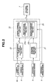
- Control unit 10 is configured to calculate a steering torque command value, based on the detection signals inputted thereto from the above-described sensors and controller and outputs the steering torque command value to steering actuator 7 and thereby applies a steering force to the steering system.
- CCD camera 8a, camera controller 8b, and wheel speed sensor 9 constitute a traveling condition detecting means or detector.
- Control unit 10 is constituted by a control block shown in FIG. 2 and includes a steering intention detecting section 21 that detects whether a driver has an intention to steer the vehicle based on a steering torque T inputted thereto from steering torque sensor 5, a target steering angle calculating section 22 that calculates a target steering angle ⁇ * necessary for the vehicle to keep the center position between the lane markings of the traveling lane, and a steering torque command value calculating section 23 that calculates a steering torque command value for performing a steering torque control in accordance with the driver's intention of steering, based on the driver's intention of steering detected by steering intention detecting section 21, target steering angle ⁇ * calculated by target steering angle calculating section 22,and steering angle ⁇ inputted from steering angle sensor 6.
- the steering torque command value calculated by steering torque command value calculating section 23 is outputted to steering actuator 7 for thereby applying a steering force to the steering system and steering front wheels 1FL, 1FR constituting the dirigible wheels.
- steering torque command value calculated by first steering torque control section 23a is outputted to steering actuator 7.
- the steering torque command value calculated by second steering torque control section 23b is outputted to steering actuator 7.
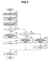
- step S1 signals from various sensors are read.
- steering torque T is read from steering torque sensor 5
- steering angle ⁇ is read from steering angle sensor 6
- lateral displacement X from the center of the traveling lane and curvature ⁇ of the traveling lane are read from camera controller 8b.
- step S2 vehicle speed V is calculated.
- Vehicle speed V is calculated by the following equation based on an average value of some of wheel speeds Vwi detected by wheel speed sensors 9FL, 9FR, 9RL, 9RR, for example, wheel speeds V WFL , V WFR of front wheels 1FL, 1FR that are not driving wheels.
- V (V WFL + V WFR )/2
- vehicle speed V is calculated based on front wheel speeds V WFL , V WFR , this is not for the purpose of limitation.
- an estimated vehicle body speed that is estimated during the anti-skid control can be used in place of vehicle speed V calculated as described above.
- the present invention is applied to a front wheel drive vehicle, it will do to calculate vehicle speed V of the own vehicle from wheel speeds V WRL , V WRR of the rear wheels which are not driving wheels.
- step S3 target steering angle ⁇ * is calculated.
- a method of calculating target steering angle ⁇ * from target yaw rate ⁇ * is used.
- an x-y relative coordinates system is set in which a current position of a vehicle W is taken as the origin, the direction of movement of vehicle W is taken as the x-axis, and a direction orthogonal to the x-axis (i.e., the widthwise direction of vehicle W) is taken as the y-axis.
- target point P on target course M is determined.
- target point arrival yaw rate ⁇ p that is caused when vehicle W travels along an imaginary course before reaching target point P
- calculation of yaw rate correction portion ⁇ ⁇ p for eliminating the angular deviation are performed sequentially
- target yaw rate ⁇ * is calculated by the following equation (2).
- ⁇ * ⁇ p - Km ⁇ p
- Km is a correction coefficient and is obtained by fuzzy estimation based on a curvature of a course along which vehicle W can travel, road width, and vehicle speed V. This is because some curvature or the like parameter of a traveling course makes it difficult for the traveling course to converge smoothly into the target course M, so that the correction coefficient Km is determined in accordance with the state variables such as curvature ⁇ and the road width.
- Target steering angle ⁇ * necessary for realizing target yaw rate ⁇ * calculated by the equation (2) is calculated by the following equation (3).
- ⁇ * L(1+KV 2 ) ⁇ ⁇ */v
- L is a wheel base of vehicle W
- K is a stability factor of steering characteristics.
- present yaw rate ⁇ and present steering angle ⁇ are the values obtained by using the yaw rate sensor and the steering angle sensor.
- step S4 judgment on the driver's intention of steering is made. Specifically, it is determined whether steering torque T read in step S1 is larger than a steering torque threshold value T 0 that is set according to vehicle speed V and steering angle ⁇ . If T>T 0 , it is determined that the driver is intentionally supplying a steering input to the steering system, and the program proceeds to step S5. If T ⁇ T 0 , it is determined that the driver is not intentionally supplying a steering input to the steering system, and the program proceeds to step S8 which will be described later.
- the target supplemental steering torque calculating map is configured so that in a range where steering angle deviation ⁇ ⁇ is relatively small, target supplemental steering torque T s increases with increase of steering angle deviation ⁇ ⁇ .
- target supplemental steering torque Ts is fixed at a constant negative value.
- a steering force generated by the target supplemental steering torque T s calculated in the manner as described above is received by the driver as a steering reaction force. This enables the driver to perform a steering operation while perceiving a deviation of the vehicle from the center position of the traveling lane.
- a lane-keep control mode that enables a driver's intention of steering to be easily or readily reflected on steering of the vehicle in the above-described manner is referred to as a second control mode.
- step S6 a count value n of a continuation time timer constituted by a software timer for measuring a continuation time of the second control mode is set at a count value n 0 corresponding to a predetermined continuation time t 0 , and thereafter the program proceeds to step S7.
- the continuation time t 0 is set at a time that is sufficiently enough not to give the driver a strange feeling at the time of shifting of the control mode of lane-keep control from the second mode to a first mode which will be described later.
- step S7 after a drive signal according to the calculated supplemental torque T s is outputted to steering actuator 7, a timer interception processing is ended and the control returns to a main program.
- step S8 it is determined whether the count value n is equal to or smaller than 0 (zero). If n ⁇ 0, it is determined that the continuation time for the above-described second control mode has elapsed and the program proceeds to step S9 where the target supplemental steering torque T s in the first control mode is calculated.
- step S3 the difference between the target steering angle and the present steering angle is multiplied by a predetermined control gain to obtain target supplemental steering torque T s and then the control proceeds to step S7.
- the lane-keep control mode for causing the vehicle to keep the center position of the traveling lane is referred to as the first control mode.
- step S8 determines that the continuation time of the second control mode has not yet elapsed; the program proceeds to step S10 where the processing similar to step S5 is performed to obtain the target supplemental steering torque T s .
- the target supplemental steering toque T s for performing the steering torque control that enables a steering operation of the driver to be readily or easily reflected on steering of the vehicle is thus calculated, and the second control mode is continued.
- step S11 decrement the count value n of the continuation timer for measuring the second control mode and thereafter proceeds to step S7.
- step S3 corresponds to a target steering angle calculating means or section
- processing in step S4 corresponds to a steering intention detecting means or section
- processing in steps S5 and S10 corresponds to a second steering torque control means or section
- processing in step S9 corresponds to a first steering torque control means or section.
- step S9 since the vehicle is not deviated from the center position of the traveling lane and therefore it is not necessary for any steering torque to be added to the steering system for forcing the vehicle to follow the traveling lane, target supplemental steering torque TS is calculated to be 0 (zero). By this, the straight-ahead running according to the steering operation of the driver is continued.
- step S3 target steering angle ⁇ * necessary for positioning the vehicle at the center of the lane is calculated based on the lane condition ahead of the vehicle and the vehicle traveling condition. If the driver is not performing a steering operation, the control proceeds from step S4 to step S8 through step S9 to calculate the target supplemental steering torque T s for making the steering angle of front wheels 1FL, 1FR that constitute dirigible wheels become equal to target steering angle ⁇ * .
- step S4 since turning of the vehicle is performed by the driver and therefore it is determined that the steering operation is performed intentionally by the driver, the control proceeds from step S4 to step S5.
- step S4 the control proceeds from step S4 to step S5 to calculate target supplemental steering torque T s according to steering angle deviation ⁇ ⁇ between target steering angle ⁇ * and steering angle ⁇ caused by the steering operation of the driver, based on the map of FIG. 5.
- step S5 the control proceeds from step S4 to step S5 to calculate target supplemental steering torque T s according to steering angle deviation ⁇ ⁇ between target steering angle ⁇ * and steering angle ⁇ caused by the steering operation of the driver, based on the map of FIG. 5.
- the second mode of steering torque control is executed so that the driver receives a steering reaction force corresponding to steering angle deviation ⁇ .
- the driver receives a larger reaction force as steering angle ⁇ caused by the steering operation of the driver becomes larger.
- the increase rate of the steering reaction force decreases with increase of steering angle ⁇
- the steering reaction force is maintained constant after steering angle deviation ⁇ ⁇ becomes larger than a predetermined value.
- the steering reaction force is controlled so as not to become larger than a predetermined value for making the steering operation of the driver be readily or easily reflected on steering of the vehicle. This enables the driver to perform a steering operation without having any strange feeling.
- the steering operation at the time of turning of the vehicle around a corner or curve may cause a deviation between target steering angle ⁇ * and steering angle ⁇ caused by a steering operation of the driver though the driver does not have an intention to deviate the vehicle from the traveling lane.
- steering angle deviation ⁇ * is relatively small, calculation is made so that a large increase in target supplemental steering torque T s is obtained even for a small increase in the steering angle deviation ⁇ for enabling the driver to receive the steering reaction force sensitively. This enables the vehicle to follow the traveling lane more stably.
- the driver can receive a steering reaction force corresponding to the amount of deviation from the center of the traveling lane, the driver.
- the driver can deviate the vehicle from the traveling lane for lane change or the like while perceiving the direction of deviation and the amount of deviation.
- the driver can perceive, from the direction of the steering torque added to the steering system as a steering reaction force, the direction of deviation from the center of the traveling lane and perceiving, from the magnitude of the steering torque, the amount of deviation of the vehicle from the center of the traveling lane.
- step S4 the control proceeds from step S4 to step S8 and then from step S8 to step S10, since the continuation time t 0 of the second mode of steering torque control has not yet elapsed and the continuation time timer n is larger than 0 (zero) (i.e., n>0, to continue the second mode of steering torque control.
- the continuation time timer n is larger than 0 (zero) (i.e., n>0, to continue the second mode of steering torque control.
- the vehicle is deviating from the traveling lane, correction of the traveling course in the direction to avoid deviation is made by applying to the steering system target supplemental steering torque T s as a steering reaction force corresponding to target steering angle ⁇ *.
- step S9 the control proceeds to step S9 as the result of determination in step S8 so that the control mode shifts to the first control mode.
- target supplemental steering torque T s that causes target steering angle ⁇ * and steering angle ⁇ of the dirigible wheels to coincide with each other.
- the control mode is shifted rapidly from the first mode to the second mode, thus making it possible to reflect the steering operation of the driver and attain a travel control that does not give the diver a strange feeling.
- the control mode is shifted from the second control mode to the first control mode after lapse of a predetermined time, thus making it possible to prevent the steering force caused in the vehicle from being varied rapidly or suddenly and thereby attain a travel control that does not give the driver a strange feeling.
- the driver's intention of steering is detected and the control mode of lane-keep control is shifted based on the driver's intention of steering. Namely, when it is determined that the driver has no intention to steer the vehicle, a travel control that attaches much importance to the lane followability is performed. When it is determined that the driver has an intention to steer the vehicle, a travel control that attaches much importance to the steering operation of the driver is performed. This makes it possible to attain a travel control that can realize stable lane-following of the vehicle and that does not give the driver a strange feeling.
- a target supplemental steering torque that causes the actual steering angle of the dirigible wheels to coincide with a target steering angle that is calculated based on the lane condition ahead of the vehicle and the vehicle traveling condition, thus making it possible to realize a sufficient lane followability and attain stable traveling of the vehicle.
- a target supplemental steering torque is produced according to the deviation between a target steering angle calculated based on the lane condition ahead of the vehicle and the vehicle traveling condition and a steering angle caused by a steering operation of the vehicle, thus making it possible to perform a travel control that reflects a steering operation of the driver and that does not give a strange feeling to the driver.
- a control mode is shifted to such one that attaches much importance to the lane followability after lapse of a predetermined time. This makes it possible to prevent the steering force of the vehicle from changing sharply or suddenly and attain a travel control that does not give the driver a strange feeling.
- the control mode when it is determined that the driver have no intention to steer the vehicle, the control mode is shifted to the first control mode after lapse of a predetermined time. In contrast to this, in the second embodiment, the control mode is shifted to the first control mode gradually within a predetermined time.
- step S6 in FIG. 3 of the first embodiment is replaced by step S21 in which the count value n for determining the control distribution ratio is set at a predetermined value n1 and steps S8 to S11 are replaced by step S22 for calculating the control distribution ratio k, step S23 for calculating a target supplemental steering torque T s 1 in the first control mode, step S24 for calculating a target supplemental steering torque T s 2 in the second control mode, step S25 for calculating the target supplemental steering torque T s according to the control distribution ratio k, step S26 for determining whether the count value n is equal to or smaller than zero (0), and step S27 for decrementing the count value n if the result of determination in step S26 is NO (negative), respectively.
- step S6 in FIG. 3 of the first embodiment is replaced by step S21 in which the count value n for determining the control distribution ratio is set at a predetermined value n1 and steps S8 to S11 are replaced by step S22 for calculating the control distribution ratio k
- step S5 target supplemental steering torque T s is calculated based on the target supplemental steering torque calculating map of FIG. 5. Then, the program proceeds to step S21 where the count value n for calculating control distribution ratio k between the steering torque in the first control mode and the steering torque in the second control mode is set at a count value n1 corresponding to a previously set transition time t1, and thereafter the program proceeds to step S7.
- an initial value of the count value n for determining the control distribution ratio k is zero (0).
- the transition time t1 is set at a sufficient time so as not to give the driver a strange feeling at the time of transition from the second control mode to the first mode.
- step S23 similarly to step S9 of FIG. 3 in the first embodiment, a target supplemental steering torque for causing the steering angle of the dirigible wheels to coincide with target steering angle ⁇ * is calculated and represented as T s 1. Then, the program proceeds to step S24.
- step S24 similarly to steps S5 and S10 of FIG. 3 in the first embodiment, a target supplemental steering torque according to the deviation ⁇ between target steering angle ⁇ * and steering angle ⁇ caused by a steering operation of the driver is calculated and represented as T s 2, and then the program proceeds to step S25.
- a final, target supplemental steering torque T s is calculated by distributing the target supplemental steering torques in the first and second control modes, which are respectively calculated in steps S23 and S24, according to the control distribution ratio k calculated in step S22.
- T s k ⁇ T s 1 + (1-k) ⁇ T S 2
- step S26 it is determined whether the count value n is equal to or lower than zero (0). If n>0, the program proceeds to step S27 to decrement the count value n and then to step S7. If n ⁇ 0, the program proceeds directly to step S7.
- target supplemental steering torque T s 1 for causing the actual steering angle of the dirigible wheels, i.e., front wheels 1FL, 1FR to coincide with target steering angle ⁇ * is calculated as target supplemental steering torque T s .
- a drive signal representative of target supplemental steering torque T s is outputted to the steering actuator.
- step S4 the program proceeds from step S4 to step S5 where the target supplemental steering torque T s according to deviation ⁇ ⁇ between target steering angle ⁇ * and actual steering angle ⁇ caused by the steering operation of the driver is calculated based on the map of FIG. 5.
- count value n for determining control distribution ration k is set at a predetermined count value n1
- a drive signal representative of the target supplemental steering torque T s is outputted to the steering actuator.
- step S25 target supplemental steering torque T s 2 for providing the driver with a steering reaction force according to steering angle deviation ⁇ ⁇ is calculated as target supplemental steering torque T s .
- step S27 After count value n is decremented in step S27, a drive signal representative of target supplemental steering torque T s is outputted to steering actuator 7 and the second mode of steering torque control is continued.
- control distribution ratio k is calculated in step S22 on the basis of count value n having been set so that n ⁇ nl, so that k ⁇ 1. For this reason, distribution of supplemental steering torque to target supplemental steering torque T s 1 in the first mode of steering torque control and target supplemental steering torque T s 2 in the second mode of steering torque control is performed according to control distribution ratio k and the final target supplemental steering torque T s is calculated based on the equation (6).
- the first steering torque control mode is executed. At this time, distribution of torque to the respective control modes is determined according to control distribution ratio k that is calculated by the equation (5).
- control distribution ratio k that is calculated by the equation (5).
- the control distribution ratio is set so that shifting to the first control mode is carried out gradually, thus making it possible to attain such a travel control that does not give the driver a strange feeling with respect to a variation in supplemental steering torque applied to the steering system.
- the mode of lane-keep control shifts immediately from the first control mode to the second control mode, thus making it possible to perform a travel control without preventing a steering interruption by the driver and without giving the driver any strange feeling.
- steering torque threshold value T 0 for determining the driver's intention of steering is set in accordance with the vehicle speed and the steering angle
- steering torque threshold value T 0 may be set in accordance with the radius of curvature of the traveling road and the kind of road that are obtained from a navigation system.
Landscapes
- Engineering & Computer Science (AREA)
- Chemical & Material Sciences (AREA)
- Combustion & Propulsion (AREA)
- Transportation (AREA)
- Mechanical Engineering (AREA)
- Steering Control In Accordance With Driving Conditions (AREA)
- Power Steering Mechanism (AREA)
Applications Claiming Priority (2)
| Application Number | Priority Date | Filing Date | Title |
|---|---|---|---|
| JP2004128337A JP4148179B2 (ja) | 2004-04-23 | 2004-04-23 | 車線維持支援装置 |
| JP2004128337 | 2004-04-23 |
Publications (3)
| Publication Number | Publication Date |
|---|---|
| EP1588922A2 true EP1588922A2 (fr) | 2005-10-26 |
| EP1588922A3 EP1588922A3 (fr) | 2006-01-11 |
| EP1588922B1 EP1588922B1 (fr) | 2010-03-31 |
Family
ID=34940925
Family Applications (1)
| Application Number | Title | Priority Date | Filing Date |
|---|---|---|---|
| EP05252452A Not-in-force EP1588922B1 (fr) | 2004-04-23 | 2005-04-19 | Système et procédé de contrôle pour véhicule autodirecteur |
Country Status (4)
| Country | Link |
|---|---|
| US (1) | US7266436B2 (fr) |
| EP (1) | EP1588922B1 (fr) |
| JP (1) | JP4148179B2 (fr) |
| DE (1) | DE602005020206D1 (fr) |
Cited By (10)
| Publication number | Priority date | Publication date | Assignee | Title |
|---|---|---|---|---|
| EP1650101A3 (fr) * | 2004-10-25 | 2006-06-07 | Favess Co. Ltd. | Appareil de commande de direction |
| EP1816066A1 (fr) | 2006-02-03 | 2007-08-08 | Shimano Inc. | Actionneur pour transmission de bicyclette commandé électriquement |
| EP2388171A1 (fr) * | 2010-05-21 | 2011-11-23 | Bayerische Motoren Werke Aktiengesellschaft | Système d'assistance au maintien de la trajectoire destiné au soutien du guidage transversal sur un véhicule automobile non lié à la voie de circulation |
| FR2968628A1 (fr) * | 2010-12-10 | 2012-06-15 | Peugeot Citroen Automobiles Sa | Procede de controle d'une fonction d'aide au suivi de voie |
| CN104512451A (zh) * | 2013-09-27 | 2015-04-15 | 富士重工业株式会社 | 车辆的车道保持控制装置 |
| DE102015006491A1 (de) * | 2015-05-22 | 2016-11-24 | Thyssenkrupp Ag | Verfahren zur Regelung eines elektrischen Stellantriebs |
| IT201700107326A1 (it) * | 2017-09-26 | 2019-03-26 | Ferrari Spa | Metodo di assistenza alla guida di un veicolo stradale |
| US20210188343A1 (en) * | 2019-12-23 | 2021-06-24 | Robert Bosch Gmbh | Method and system for steering intervention by electronic power steering unit to prevent vehicle rollover or loss of control |
| US20220073135A1 (en) * | 2020-09-09 | 2022-03-10 | Hyundai Mobis Co., Ltd. | Steering control system and method for vehicle |
| US11851056B2 (en) | 2019-05-13 | 2023-12-26 | Volkswagen Aktiengesellschaft | Method for ending a drive of a transportation vehicle |
Families Citing this family (51)
| Publication number | Priority date | Publication date | Assignee | Title |
|---|---|---|---|---|
| JP4558445B2 (ja) * | 2004-10-21 | 2010-10-06 | 本田技研工業株式会社 | 操舵装置 |
| DE102005014114A1 (de) * | 2005-03-21 | 2006-10-05 | Valeo Schalter Und Sensoren Gmbh | Spurerkennungssystem und Verfahren |
| DE102005026479B4 (de) * | 2005-06-09 | 2017-04-20 | Daimler Ag | Verfahren zur Unaufmerksamkeitserkennung in Abhängigkeit von mindestens einem fahrerindividuellen Parameter |
| EP1849669B1 (fr) * | 2006-04-28 | 2011-10-05 | Nissan Motor Co., Ltd. | Appareil et procédé de prévention de suivi de voie pour véhicule automobile |
| US7885730B2 (en) * | 2007-01-26 | 2011-02-08 | Nexteer (Beijing) Technology Co., Ltd. | Systems, methods and computer program products for lane change detection and handling of lane keeping torque |
| KR100941271B1 (ko) * | 2007-03-30 | 2010-02-11 | 현대자동차주식회사 | 자동차용 차선이탈 방지 방법 |
| DE102007020280A1 (de) * | 2007-04-30 | 2008-11-06 | Robert Bosch Gmbh | Verfahren und Vorrichtung für die Steuerung eines Fahrerassistenzsystems |
| JP4875027B2 (ja) * | 2008-07-09 | 2012-02-15 | 三菱電機株式会社 | 車両制御装置 |
| JP5386873B2 (ja) * | 2008-07-30 | 2014-01-15 | 日産自動車株式会社 | 車両用操舵装置及び車両用操舵方法 |
| JP5027756B2 (ja) * | 2008-08-06 | 2012-09-19 | 本田技研工業株式会社 | 運転支援装置 |
| JP2010188854A (ja) * | 2009-02-18 | 2010-09-02 | Nissan Motor Co Ltd | 車線維持支援装置及び車線維持支援方法 |
| JP5262816B2 (ja) * | 2009-02-19 | 2013-08-14 | 日産自動車株式会社 | 車両用走行制御装置および車両用走行制御装置の制御方法 |
| JP5245905B2 (ja) * | 2009-02-23 | 2013-07-24 | 日産自動車株式会社 | 車線維持支援装置及び車線維持支援方法 |
| JP2011005893A (ja) * | 2009-06-23 | 2011-01-13 | Nissan Motor Co Ltd | 車両の走行制御装置および車両の走行制御方法 |
| WO2011002348A1 (fr) * | 2009-06-29 | 2011-01-06 | Volvo Lastvagnar Ab | Procédé et système pour le changement d'une trajectoire de véhicule |
| JP5314539B2 (ja) * | 2009-08-31 | 2013-10-16 | 富士重工業株式会社 | 車両の操舵支援制御装置 |
| JP5365607B2 (ja) * | 2010-11-10 | 2013-12-11 | トヨタ自動車株式会社 | 操舵装置 |
| JP2012232704A (ja) | 2011-05-09 | 2012-11-29 | Jtekt Corp | 車両用操舵装置 |
| US9274525B1 (en) * | 2012-09-28 | 2016-03-01 | Google Inc. | Detecting sensor degradation by actively controlling an autonomous vehicle |
| KR101502510B1 (ko) | 2013-11-26 | 2015-03-13 | 현대모비스 주식회사 | 차량의 차선 유지 제어 장치 및 방법 |
| JP5991340B2 (ja) * | 2014-04-28 | 2016-09-14 | トヨタ自動車株式会社 | 運転支援装置 |
| FR3022515B1 (fr) * | 2014-06-24 | 2016-07-29 | Jtekt Europe Sas | Assistance de direction mixte comprenant une boucle d'asservissement en couple pilotee en consigne par un controleur de position destine a l'asservissement en trajectoire |
| JP6520506B2 (ja) * | 2014-09-03 | 2019-05-29 | 株式会社デンソー | 車両の走行制御システム |
| KR101659034B1 (ko) * | 2015-01-20 | 2016-09-23 | 엘지전자 주식회사 | 차량의 주행 모드 전환 장치 및 그 방법 |
| JP6412457B2 (ja) * | 2015-03-31 | 2018-10-24 | 株式会社デンソー | 運転支援装置、及び運転支援方法 |
| JP2016222180A (ja) * | 2015-06-02 | 2016-12-28 | 富士重工業株式会社 | 車両操舵制御装置 |
| JP6413953B2 (ja) * | 2015-06-29 | 2018-10-31 | 株式会社デンソー | 車線逸脱回避システム |
| JP6515783B2 (ja) * | 2015-10-23 | 2019-05-22 | トヨタ自動車株式会社 | 車両の操舵反力制御装置 |
| JP6515754B2 (ja) * | 2015-09-08 | 2019-05-22 | トヨタ自動車株式会社 | 車両の操舵反力制御装置 |
| JP6252575B2 (ja) * | 2015-09-28 | 2017-12-27 | トヨタ自動車株式会社 | 自動運転装置 |
| JP6691387B2 (ja) | 2016-02-15 | 2020-04-28 | 本田技研工業株式会社 | 車両維持制御装置 |
| JP6722078B2 (ja) * | 2016-09-28 | 2020-07-15 | 株式会社Subaru | 車両の操舵制御装置 |
| US10814913B2 (en) | 2017-04-12 | 2020-10-27 | Toyota Jidosha Kabushiki Kaisha | Lane change assist apparatus for vehicle |
| JP6627821B2 (ja) | 2017-06-06 | 2020-01-08 | トヨタ自動車株式会社 | 車線変更支援装置 |
| JP6642522B2 (ja) * | 2017-06-06 | 2020-02-05 | トヨタ自動車株式会社 | 車線変更支援装置 |
| JP6627822B2 (ja) | 2017-06-06 | 2020-01-08 | トヨタ自動車株式会社 | 車線変更支援装置 |
| JP6568559B2 (ja) * | 2017-09-13 | 2019-08-28 | 株式会社Subaru | 車両の走行制御装置 |
| US11273836B2 (en) * | 2017-12-18 | 2022-03-15 | Plusai, Inc. | Method and system for human-like driving lane planning in autonomous driving vehicles |
| US11130497B2 (en) * | 2017-12-18 | 2021-09-28 | Plusai Limited | Method and system for ensemble vehicle control prediction in autonomous driving vehicles |
| US20190185012A1 (en) | 2017-12-18 | 2019-06-20 | PlusAI Corp | Method and system for personalized motion planning in autonomous driving vehicles |
| KR102553247B1 (ko) * | 2018-04-27 | 2023-07-07 | 주식회사 에이치엘클레무브 | 전방 차량 추종 제어 시 안전성을 향상할 수 있는 차선 유지 보조 시스템 및 방법 |
| JP6954868B2 (ja) * | 2018-07-11 | 2021-10-27 | トヨタ自動車株式会社 | 運転支援システム |
| JP6637553B1 (ja) * | 2018-07-26 | 2020-01-29 | 株式会社Subaru | 車両制御装置 |
| US11227409B1 (en) | 2018-08-20 | 2022-01-18 | Waymo Llc | Camera assessment techniques for autonomous vehicles |
| US11699207B2 (en) | 2018-08-20 | 2023-07-11 | Waymo Llc | Camera assessment techniques for autonomous vehicles |
| KR102155817B1 (ko) * | 2019-01-30 | 2020-09-16 | 주식회사 만도 | 차량의 직진 주행 편의성 향상을 위한 조향 장치 및 그 제어 방법 |
| JP7375555B2 (ja) * | 2020-01-08 | 2023-11-08 | 株式会社村田製作所 | 把持負荷検出デバイス |
| CN113715902B (zh) * | 2020-05-26 | 2022-11-15 | 北京新能源汽车股份有限公司 | 一种车辆的控制方法及装置 |
| JP2022060078A (ja) * | 2020-10-02 | 2022-04-14 | 株式会社Subaru | 運転支援装置 |
| JP7472866B2 (ja) * | 2021-07-06 | 2024-04-23 | トヨタ自動車株式会社 | 車両用操舵ガイドトルク制御装置 |
| JP7548258B2 (ja) | 2022-03-14 | 2024-09-10 | トヨタ自動車株式会社 | 車両制御装置 |
Citations (1)
| Publication number | Priority date | Publication date | Assignee | Title |
|---|---|---|---|---|
| JPH09207800A (ja) | 1996-02-07 | 1997-08-12 | Honda Motor Co Ltd | 車両用操舵装置 |
Family Cites Families (6)
| Publication number | Priority date | Publication date | Assignee | Title |
|---|---|---|---|---|
| JP3314866B2 (ja) * | 1997-09-13 | 2002-08-19 | 本田技研工業株式会社 | 車両用操舵装置 |
| JP3571234B2 (ja) * | 1998-10-12 | 2004-09-29 | 本田技研工業株式会社 | 車両用操舵制御装置 |
| JP3694423B2 (ja) * | 1999-06-25 | 2005-09-14 | 本田技研工業株式会社 | 車両および車両用操舵制御装置 |
| JP2003154960A (ja) * | 2001-09-04 | 2003-05-27 | Honda Motor Co Ltd | 車両の操舵制御装置 |
| JP4496760B2 (ja) * | 2003-10-29 | 2010-07-07 | 日産自動車株式会社 | 車線逸脱防止装置 |
| JP3982483B2 (ja) * | 2003-11-13 | 2007-09-26 | 日産自動車株式会社 | 車線逸脱防止装置 |
-
2004
- 2004-04-23 JP JP2004128337A patent/JP4148179B2/ja not_active Expired - Lifetime
-
2005
- 2005-04-19 EP EP05252452A patent/EP1588922B1/fr not_active Not-in-force
- 2005-04-19 DE DE602005020206T patent/DE602005020206D1/de active Active
- 2005-04-21 US US11/110,904 patent/US7266436B2/en not_active Expired - Fee Related
Patent Citations (1)
| Publication number | Priority date | Publication date | Assignee | Title |
|---|---|---|---|---|
| JPH09207800A (ja) | 1996-02-07 | 1997-08-12 | Honda Motor Co Ltd | 車両用操舵装置 |
Cited By (15)
| Publication number | Priority date | Publication date | Assignee | Title |
|---|---|---|---|---|
| EP1650101A3 (fr) * | 2004-10-25 | 2006-06-07 | Favess Co. Ltd. | Appareil de commande de direction |
| EP1816066A1 (fr) | 2006-02-03 | 2007-08-08 | Shimano Inc. | Actionneur pour transmission de bicyclette commandé électriquement |
| EP2388171A1 (fr) * | 2010-05-21 | 2011-11-23 | Bayerische Motoren Werke Aktiengesellschaft | Système d'assistance au maintien de la trajectoire destiné au soutien du guidage transversal sur un véhicule automobile non lié à la voie de circulation |
| FR2968628A1 (fr) * | 2010-12-10 | 2012-06-15 | Peugeot Citroen Automobiles Sa | Procede de controle d'une fonction d'aide au suivi de voie |
| CN104512451B (zh) * | 2013-09-27 | 2017-06-20 | 株式会社斯巴鲁 | 车辆的车道保持控制装置 |
| CN104512451A (zh) * | 2013-09-27 | 2015-04-15 | 富士重工业株式会社 | 车辆的车道保持控制装置 |
| DE102015006491A1 (de) * | 2015-05-22 | 2016-11-24 | Thyssenkrupp Ag | Verfahren zur Regelung eines elektrischen Stellantriebs |
| IT201700107326A1 (it) * | 2017-09-26 | 2019-03-26 | Ferrari Spa | Metodo di assistenza alla guida di un veicolo stradale |
| EP3459824A1 (fr) | 2017-09-26 | 2019-03-27 | FERRARI S.p.A. | Procédé d'assistance au conducteur d'un véhicule routier |
| US10906582B2 (en) | 2017-09-26 | 2021-02-02 | Ferrari S.P.A. | Method for the driver assistance of a road vehicle |
| US11851056B2 (en) | 2019-05-13 | 2023-12-26 | Volkswagen Aktiengesellschaft | Method for ending a drive of a transportation vehicle |
| US20210188343A1 (en) * | 2019-12-23 | 2021-06-24 | Robert Bosch Gmbh | Method and system for steering intervention by electronic power steering unit to prevent vehicle rollover or loss of control |
| US11654956B2 (en) * | 2019-12-23 | 2023-05-23 | Robert Bosch Gmbh | Method and system for steering intervention by electronic power steering unit to prevent vehicle rollover or loss of control |
| US20220073135A1 (en) * | 2020-09-09 | 2022-03-10 | Hyundai Mobis Co., Ltd. | Steering control system and method for vehicle |
| US11814122B2 (en) * | 2020-09-09 | 2023-11-14 | Hyundai Mobis Co., Ltd. | Steering control system and method for vehicle |
Also Published As
| Publication number | Publication date |
|---|---|
| US20050240328A1 (en) | 2005-10-27 |
| US7266436B2 (en) | 2007-09-04 |
| DE602005020206D1 (de) | 2010-05-12 |
| JP2005306283A (ja) | 2005-11-04 |
| JP4148179B2 (ja) | 2008-09-10 |
| EP1588922B1 (fr) | 2010-03-31 |
| EP1588922A3 (fr) | 2006-01-11 |
Similar Documents
| Publication | Publication Date | Title |
|---|---|---|
| US7266436B2 (en) | Lane-keep control system and method for vehicle | |
| US7457694B2 (en) | Driving assist system for vehicle | |
| US10649454B2 (en) | Autonomous vehicle | |
| US6970787B2 (en) | Automotive lane deviation avoidance system | |
| US9211911B2 (en) | Method for steering assistance during an emergency maneuver | |
| US6708098B2 (en) | Lane-keep control system for vehicle | |
| US7117076B2 (en) | Lane keep control apparatus and method for automotive vehicle | |
| EP1170195B1 (fr) | Contrôle de véhicule pour le suivi d'une voie | |
| US7236884B2 (en) | Automotive lane deviation prevention apparatus | |
| JP3906821B2 (ja) | 車線逸脱防止装置 | |
| US20050004731A1 (en) | Drive-assist system | |
| EP1251060A2 (fr) | Appareil et méthode pour la commande d'un véhicule | |
| EP1275573A2 (fr) | Contrôle de suivi de voie pour véhicule | |
| JP6952014B2 (ja) | 車両制御装置、車両制御方法、及び車両制御システム | |
| US20080208409A1 (en) | Vehicle dynamics control apparatus | |
| JP2003154910A (ja) | 車線逸脱防止装置 | |
| JP5227082B2 (ja) | 4輪操舵機構を搭載した車両の操舵制御装置 | |
| JPH11198844A (ja) | 操舵力制御装置 | |
| JP3800087B2 (ja) | 車線逸脱防止装置 | |
| JP3864892B2 (ja) | 車線逸脱防止装置 | |
| JP4403962B2 (ja) | 自動操舵制御装置 | |
| JP2871415B2 (ja) | 車両の自動走行制御装置 | |
| JP4501967B2 (ja) | 車線逸脱防止装置 | |
| JP2001354124A (ja) | 車両の走行安全装置 | |
| JPH1178952A (ja) | 車両用操舵装置 |
Legal Events
| Date | Code | Title | Description |
|---|---|---|---|
| PUAI | Public reference made under article 153(3) epc to a published international application that has entered the european phase |
Free format text: ORIGINAL CODE: 0009012 |
|
| 17P | Request for examination filed |
Effective date: 20050504 |
|
| AK | Designated contracting states |
Kind code of ref document: A2 Designated state(s): AT BE BG CH CY CZ DE DK EE ES FI FR GB GR HU IE IS IT LI LT LU MC NL PL PT RO SE SI SK TR |
|
| AX | Request for extension of the european patent |
Extension state: AL BA HR LV MK YU |
|
| PUAL | Search report despatched |
Free format text: ORIGINAL CODE: 0009013 |
|
| AK | Designated contracting states |
Kind code of ref document: A3 Designated state(s): AT BE BG CH CY CZ DE DK EE ES FI FR GB GR HU IE IS IT LI LT LU MC NL PL PT RO SE SI SK TR |
|
| AX | Request for extension of the european patent |
Extension state: AL BA HR LV MK YU |
|
| AKX | Designation fees paid |
Designated state(s): DE FR GB |
|
| 17Q | First examination report despatched |
Effective date: 20061207 |
|
| GRAP | Despatch of communication of intention to grant a patent |
Free format text: ORIGINAL CODE: EPIDOSNIGR1 |
|
| GRAS | Grant fee paid |
Free format text: ORIGINAL CODE: EPIDOSNIGR3 |
|
| GRAA | (expected) grant |
Free format text: ORIGINAL CODE: 0009210 |
|
| AK | Designated contracting states |
Kind code of ref document: B1 Designated state(s): DE FR GB |
|
| REG | Reference to a national code |
Ref country code: GB Ref legal event code: FG4D |
|
| REF | Corresponds to: |
Ref document number: 602005020206 Country of ref document: DE Date of ref document: 20100512 Kind code of ref document: P |
|
| PLBE | No opposition filed within time limit |
Free format text: ORIGINAL CODE: 0009261 |
|
| STAA | Information on the status of an ep patent application or granted ep patent |
Free format text: STATUS: NO OPPOSITION FILED WITHIN TIME LIMIT |
|
| 26N | No opposition filed |
Effective date: 20110104 |
|
| REG | Reference to a national code |
Ref country code: FR Ref legal event code: PLFP Year of fee payment: 11 |
|
| PGFP | Annual fee paid to national office [announced via postgrant information from national office to epo] |
Ref country code: GB Payment date: 20150415 Year of fee payment: 11 Ref country code: DE Payment date: 20150414 Year of fee payment: 11 |
|
| PGFP | Annual fee paid to national office [announced via postgrant information from national office to epo] |
Ref country code: FR Payment date: 20150408 Year of fee payment: 11 |
|
| REG | Reference to a national code |
Ref country code: DE Ref legal event code: R119 Ref document number: 602005020206 Country of ref document: DE |
|
| GBPC | Gb: european patent ceased through non-payment of renewal fee |
Effective date: 20160419 |
|
| REG | Reference to a national code |
Ref country code: FR Ref legal event code: ST Effective date: 20161230 |
|
| PG25 | Lapsed in a contracting state [announced via postgrant information from national office to epo] |
Ref country code: FR Free format text: LAPSE BECAUSE OF NON-PAYMENT OF DUE FEES Effective date: 20160502 Ref country code: DE Free format text: LAPSE BECAUSE OF NON-PAYMENT OF DUE FEES Effective date: 20161101 Ref country code: GB Free format text: LAPSE BECAUSE OF NON-PAYMENT OF DUE FEES Effective date: 20160419 |