EP1570895A2 - Système pour le traitement des gaz d'échappement et système catalytique - Google Patents
Système pour le traitement des gaz d'échappement et système catalytique Download PDFInfo
- Publication number
- EP1570895A2 EP1570895A2 EP05075504A EP05075504A EP1570895A2 EP 1570895 A2 EP1570895 A2 EP 1570895A2 EP 05075504 A EP05075504 A EP 05075504A EP 05075504 A EP05075504 A EP 05075504A EP 1570895 A2 EP1570895 A2 EP 1570895A2
- Authority
- EP
- European Patent Office
- Prior art keywords
- catalyst
- gold
- equal
- hydrocarbon
- catalyst system
- Prior art date
- Legal status (The legal status is an assumption and is not a legal conclusion. Google has not performed a legal analysis and makes no representation as to the accuracy of the status listed.)
- Granted
Links
- 239000003054 catalyst Substances 0.000 title claims abstract description 205
- 239000010931 gold Substances 0.000 claims abstract description 148
- PCHJSUWPFVWCPO-UHFFFAOYSA-N gold Chemical compound [Au] PCHJSUWPFVWCPO-UHFFFAOYSA-N 0.000 claims abstract description 146
- 229910052737 gold Inorganic materials 0.000 claims abstract description 146
- 239000000463 material Substances 0.000 claims abstract description 78
- 229930195733 hydrocarbon Natural products 0.000 claims abstract description 66
- 150000002430 hydrocarbons Chemical class 0.000 claims abstract description 66
- 230000003647 oxidation Effects 0.000 claims abstract description 43
- 238000007254 oxidation reaction Methods 0.000 claims abstract description 43
- 239000004215 Carbon black (E152) Substances 0.000 claims abstract description 36
- 230000001590 oxidative effect Effects 0.000 claims abstract description 14
- 239000000758 substrate Substances 0.000 claims description 37
- 229910002091 carbon monoxide Inorganic materials 0.000 claims description 33
- PNEYBMLMFCGWSK-UHFFFAOYSA-N aluminium oxide Inorganic materials [O-2].[O-2].[O-2].[Al+3].[Al+3] PNEYBMLMFCGWSK-UHFFFAOYSA-N 0.000 claims description 25
- 238000011144 upstream manufacturing Methods 0.000 claims description 24
- 239000010457 zeolite Substances 0.000 claims description 18
- 238000000034 method Methods 0.000 claims description 17
- 239000002245 particle Substances 0.000 claims description 17
- 229910021536 Zeolite Inorganic materials 0.000 claims description 14
- HNPSIPDUKPIQMN-UHFFFAOYSA-N dioxosilane;oxo(oxoalumanyloxy)alumane Chemical compound O=[Si]=O.O=[Al]O[Al]=O HNPSIPDUKPIQMN-UHFFFAOYSA-N 0.000 claims description 11
- 239000006069 physical mixture Substances 0.000 claims description 11
- BASFCYQUMIYNBI-UHFFFAOYSA-N platinum Chemical group [Pt] BASFCYQUMIYNBI-UHFFFAOYSA-N 0.000 claims description 10
- KDLHZDBZIXYQEI-UHFFFAOYSA-N Palladium Chemical compound [Pd] KDLHZDBZIXYQEI-UHFFFAOYSA-N 0.000 claims description 6
- 238000001179 sorption measurement Methods 0.000 claims description 6
- 229910052697 platinum Inorganic materials 0.000 claims description 5
- 229910052763 palladium Inorganic materials 0.000 claims description 3
- 238000004887 air purification Methods 0.000 claims 1
- DIOQZVSQGTUSAI-UHFFFAOYSA-N decane Chemical compound CCCCCCCCCC DIOQZVSQGTUSAI-UHFFFAOYSA-N 0.000 description 39
- 229910044991 metal oxide Inorganic materials 0.000 description 33
- 150000004706 metal oxides Chemical class 0.000 description 33
- UGFAIRIUMAVXCW-UHFFFAOYSA-N Carbon monoxide Chemical compound [O+]#[C-] UGFAIRIUMAVXCW-UHFFFAOYSA-N 0.000 description 31
- 239000012530 fluid Substances 0.000 description 21
- 239000000243 solution Substances 0.000 description 21
- 238000001354 calcination Methods 0.000 description 15
- 230000014759 maintenance of location Effects 0.000 description 15
- -1 soot and the like) Chemical class 0.000 description 14
- 238000003878 thermal aging Methods 0.000 description 14
- XLYOFNOQVPJJNP-UHFFFAOYSA-N water Substances O XLYOFNOQVPJJNP-UHFFFAOYSA-N 0.000 description 14
- 239000000203 mixture Substances 0.000 description 13
- HEMHJVSKTPXQMS-UHFFFAOYSA-M Sodium hydroxide Chemical compound [OH-].[Na+] HEMHJVSKTPXQMS-UHFFFAOYSA-M 0.000 description 12
- 239000003463 adsorbent Substances 0.000 description 12
- 238000006243 chemical reaction Methods 0.000 description 12
- 150000002344 gold compounds Chemical class 0.000 description 12
- 229910021505 gold(III) hydroxide Inorganic materials 0.000 description 11
- WDZVNNYQBQRJRX-UHFFFAOYSA-K gold(iii) hydroxide Chemical compound O[Au](O)O WDZVNNYQBQRJRX-UHFFFAOYSA-K 0.000 description 11
- MWUXSHHQAYIFBG-UHFFFAOYSA-N nitrogen oxide Inorganic materials O=[N] MWUXSHHQAYIFBG-UHFFFAOYSA-N 0.000 description 10
- 229910001868 water Inorganic materials 0.000 description 10
- GWEVSGVZZGPLCZ-UHFFFAOYSA-N Titan oxide Chemical compound O=[Ti]=O GWEVSGVZZGPLCZ-UHFFFAOYSA-N 0.000 description 9
- VEXZGXHMUGYJMC-UHFFFAOYSA-M Chloride anion Chemical compound [Cl-] VEXZGXHMUGYJMC-UHFFFAOYSA-M 0.000 description 8
- 239000002002 slurry Substances 0.000 description 8
- 239000007789 gas Substances 0.000 description 7
- 229910052751 metal Inorganic materials 0.000 description 7
- 239000002184 metal Substances 0.000 description 7
- 229910004042 HAuCl4 Inorganic materials 0.000 description 6
- 239000002253 acid Substances 0.000 description 6
- 230000003197 catalytic effect Effects 0.000 description 6
- 238000005406 washing Methods 0.000 description 6
- 238000001035 drying Methods 0.000 description 5
- 239000003446 ligand Substances 0.000 description 5
- 230000009467 reduction Effects 0.000 description 5
- 238000006722 reduction reaction Methods 0.000 description 5
- 238000012360 testing method Methods 0.000 description 5
- CSCPPACGZOOCGX-UHFFFAOYSA-N Acetone Chemical compound CC(C)=O CSCPPACGZOOCGX-UHFFFAOYSA-N 0.000 description 4
- VYPSYNLAJGMNEJ-UHFFFAOYSA-N Silicium dioxide Chemical compound O=[Si]=O VYPSYNLAJGMNEJ-UHFFFAOYSA-N 0.000 description 4
- 150000001875 compounds Chemical class 0.000 description 4
- 230000009849 deactivation Effects 0.000 description 4
- 238000002474 experimental method Methods 0.000 description 4
- 239000007788 liquid Substances 0.000 description 4
- 238000004519 manufacturing process Methods 0.000 description 4
- 239000011148 porous material Substances 0.000 description 4
- 239000002244 precipitate Substances 0.000 description 4
- 239000002904 solvent Substances 0.000 description 4
- 229910001220 stainless steel Inorganic materials 0.000 description 4
- CURLTUGMZLYLDI-UHFFFAOYSA-N Carbon dioxide Chemical compound O=C=O CURLTUGMZLYLDI-UHFFFAOYSA-N 0.000 description 3
- 230000010718 Oxidation Activity Effects 0.000 description 3
- KWYUFKZDYYNOTN-UHFFFAOYSA-M Potassium hydroxide Chemical compound [OH-].[K+] KWYUFKZDYYNOTN-UHFFFAOYSA-M 0.000 description 3
- 238000004891 communication Methods 0.000 description 3
- 239000011888 foil Substances 0.000 description 3
- 238000010438 heat treatment Methods 0.000 description 3
- XLYOFNOQVPJJNP-UHFFFAOYSA-M hydroxide Chemical class [OH-] XLYOFNOQVPJJNP-UHFFFAOYSA-M 0.000 description 3
- 238000011068 loading method Methods 0.000 description 3
- 229910001415 sodium ion Inorganic materials 0.000 description 3
- 238000003756 stirring Methods 0.000 description 3
- IJGRMHOSHXDMSA-UHFFFAOYSA-N Atomic nitrogen Chemical compound N#N IJGRMHOSHXDMSA-UHFFFAOYSA-N 0.000 description 2
- UQSXHKLRYXJYBZ-UHFFFAOYSA-N Iron oxide Chemical compound [Fe]=O UQSXHKLRYXJYBZ-UHFFFAOYSA-N 0.000 description 2
- NINIDFKCEFEMDL-UHFFFAOYSA-N Sulfur Chemical compound [S] NINIDFKCEFEMDL-UHFFFAOYSA-N 0.000 description 2
- MCMNRKCIXSYSNV-UHFFFAOYSA-N Zirconium dioxide Chemical compound O=[Zr]=O MCMNRKCIXSYSNV-UHFFFAOYSA-N 0.000 description 2
- 239000006096 absorbing agent Substances 0.000 description 2
- 229910000323 aluminium silicate Inorganic materials 0.000 description 2
- 239000011230 binding agent Substances 0.000 description 2
- 230000015572 biosynthetic process Effects 0.000 description 2
- 229910002092 carbon dioxide Inorganic materials 0.000 description 2
- 150000001768 cations Chemical class 0.000 description 2
- 238000005119 centrifugation Methods 0.000 description 2
- 229910010293 ceramic material Inorganic materials 0.000 description 2
- 239000003153 chemical reaction reagent Substances 0.000 description 2
- 229910052593 corundum Inorganic materials 0.000 description 2
- 238000010908 decantation Methods 0.000 description 2
- 239000008367 deionised water Substances 0.000 description 2
- 229910021641 deionized water Inorganic materials 0.000 description 2
- 230000008021 deposition Effects 0.000 description 2
- JSKIRARMQDRGJZ-UHFFFAOYSA-N dimagnesium dioxido-bis[(1-oxido-3-oxo-2,4,6,8,9-pentaoxa-1,3-disila-5,7-dialuminabicyclo[3.3.1]nonan-7-yl)oxy]silane Chemical compound [Mg++].[Mg++].[O-][Si]([O-])(O[Al]1O[Al]2O[Si](=O)O[Si]([O-])(O1)O2)O[Al]1O[Al]2O[Si](=O)O[Si]([O-])(O1)O2 JSKIRARMQDRGJZ-UHFFFAOYSA-N 0.000 description 2
- 238000001914 filtration Methods 0.000 description 2
- 239000011521 glass Substances 0.000 description 2
- 229910052809 inorganic oxide Inorganic materials 0.000 description 2
- 239000008188 pellet Substances 0.000 description 2
- 238000001556 precipitation Methods 0.000 description 2
- 239000010453 quartz Substances 0.000 description 2
- CPRMKOQKXYSDML-UHFFFAOYSA-M rubidium hydroxide Chemical compound [OH-].[Rb+] CPRMKOQKXYSDML-UHFFFAOYSA-M 0.000 description 2
- 150000003839 salts Chemical class 0.000 description 2
- 238000000926 separation method Methods 0.000 description 2
- 239000007787 solid Substances 0.000 description 2
- 229910052717 sulfur Inorganic materials 0.000 description 2
- 239000011593 sulfur Substances 0.000 description 2
- 229910001845 yogo sapphire Inorganic materials 0.000 description 2
- MFGOFGRYDNHJTA-UHFFFAOYSA-N 2-amino-1-(2-fluorophenyl)ethanol Chemical compound NCC(O)C1=CC=CC=C1F MFGOFGRYDNHJTA-UHFFFAOYSA-N 0.000 description 1
- QGZKDVFQNNGYKY-UHFFFAOYSA-O Ammonium Chemical compound [NH4+] QGZKDVFQNNGYKY-UHFFFAOYSA-O 0.000 description 1
- ATRRKUHOCOJYRX-UHFFFAOYSA-N Ammonium bicarbonate Chemical compound [NH4+].OC([O-])=O ATRRKUHOCOJYRX-UHFFFAOYSA-N 0.000 description 1
- VHUUQVKOLVNVRT-UHFFFAOYSA-N Ammonium hydroxide Chemical compound [NH4+].[OH-] VHUUQVKOLVNVRT-UHFFFAOYSA-N 0.000 description 1
- BVKZGUZCCUSVTD-UHFFFAOYSA-L Carbonate Chemical compound [O-]C([O-])=O BVKZGUZCCUSVTD-UHFFFAOYSA-L 0.000 description 1
- KRKNYBCHXYNGOX-UHFFFAOYSA-K Citrate Chemical compound [O-]C(=O)CC(O)(CC([O-])=O)C([O-])=O KRKNYBCHXYNGOX-UHFFFAOYSA-K 0.000 description 1
- CWYNVVGOOAEACU-UHFFFAOYSA-N Fe2+ Chemical compound [Fe+2] CWYNVVGOOAEACU-UHFFFAOYSA-N 0.000 description 1
- 229910003767 Gold(III) bromide Inorganic materials 0.000 description 1
- 229910021604 Rhodium(III) chloride Inorganic materials 0.000 description 1
- FCUFAHVIZMPWGD-UHFFFAOYSA-N [O-][N+](=O)[Pt](N)(N)[N+]([O-])=O Chemical compound [O-][N+](=O)[Pt](N)(N)[N+]([O-])=O FCUFAHVIZMPWGD-UHFFFAOYSA-N 0.000 description 1
- 238000013019 agitation Methods 0.000 description 1
- 239000001099 ammonium carbonate Substances 0.000 description 1
- 235000012501 ammonium carbonate Nutrition 0.000 description 1
- 239000000908 ammonium hydroxide Substances 0.000 description 1
- 238000013459 approach Methods 0.000 description 1
- 239000007864 aqueous solution Substances 0.000 description 1
- QVGXLLKOCUKJST-UHFFFAOYSA-N atomic oxygen Chemical compound [O] QVGXLLKOCUKJST-UHFFFAOYSA-N 0.000 description 1
- NOWPEMKUZKNSGG-UHFFFAOYSA-N azane;platinum(2+) Chemical compound N.N.N.N.[Pt+2] NOWPEMKUZKNSGG-UHFFFAOYSA-N 0.000 description 1
- HUCVOHYBFXVBRW-UHFFFAOYSA-M caesium hydroxide Inorganic materials [OH-].[Cs+] HUCVOHYBFXVBRW-UHFFFAOYSA-M 0.000 description 1
- 239000001569 carbon dioxide Substances 0.000 description 1
- ADGFUTSPEKVFKD-UHFFFAOYSA-N carbonyl dichloride;rhodium Chemical compound [Rh].ClC(Cl)=O ADGFUTSPEKVFKD-UHFFFAOYSA-N 0.000 description 1
- 239000012018 catalyst precursor Substances 0.000 description 1
- 238000006555 catalytic reaction Methods 0.000 description 1
- 239000000919 ceramic Substances 0.000 description 1
- CETPSERCERDGAM-UHFFFAOYSA-N ceric oxide Chemical compound O=[Ce]=O CETPSERCERDGAM-UHFFFAOYSA-N 0.000 description 1
- 229910000422 cerium(IV) oxide Inorganic materials 0.000 description 1
- 239000000460 chlorine Substances 0.000 description 1
- 229910052801 chlorine Inorganic materials 0.000 description 1
- 238000000975 co-precipitation Methods 0.000 description 1
- 210000001520 comb Anatomy 0.000 description 1
- 238000002485 combustion reaction Methods 0.000 description 1
- 239000002131 composite material Substances 0.000 description 1
- 238000001816 cooling Methods 0.000 description 1
- 229910052878 cordierite Inorganic materials 0.000 description 1
- 238000005260 corrosion Methods 0.000 description 1
- 230000007797 corrosion Effects 0.000 description 1
- 230000001419 dependent effect Effects 0.000 description 1
- 238000013461 design Methods 0.000 description 1
- 239000006185 dispersion Substances 0.000 description 1
- 239000012153 distilled water Substances 0.000 description 1
- 230000009977 dual effect Effects 0.000 description 1
- 230000000694 effects Effects 0.000 description 1
- 239000000835 fiber Substances 0.000 description 1
- 239000002657 fibrous material Substances 0.000 description 1
- 239000006260 foam Substances 0.000 description 1
- OVWPJGBVJCTEBJ-UHFFFAOYSA-K gold tribromide Chemical compound Br[Au](Br)Br OVWPJGBVJCTEBJ-UHFFFAOYSA-K 0.000 description 1
- NIXONLGLPJQPCW-UHFFFAOYSA-K gold trifluoride Chemical compound F[Au](F)F NIXONLGLPJQPCW-UHFFFAOYSA-K 0.000 description 1
- 239000008187 granular material Substances 0.000 description 1
- 235000012907 honey Nutrition 0.000 description 1
- 150000004679 hydroxides Chemical class 0.000 description 1
- 238000005470 impregnation Methods 0.000 description 1
- 238000011065 in-situ storage Methods 0.000 description 1
- 230000003993 interaction Effects 0.000 description 1
- JEIPFZHSYJVQDO-UHFFFAOYSA-N iron(III) oxide Inorganic materials O=[Fe]O[Fe]=O JEIPFZHSYJVQDO-UHFFFAOYSA-N 0.000 description 1
- 230000001788 irregular Effects 0.000 description 1
- 229910000464 lead oxide Inorganic materials 0.000 description 1
- 238000005259 measurement Methods 0.000 description 1
- 238000002156 mixing Methods 0.000 description 1
- 238000012986 modification Methods 0.000 description 1
- 230000004048 modification Effects 0.000 description 1
- 239000002808 molecular sieve Substances 0.000 description 1
- 230000007935 neutral effect Effects 0.000 description 1
- 238000006386 neutralization reaction Methods 0.000 description 1
- SNICXCGAKADSCV-UHFFFAOYSA-N nicotine Chemical compound CN1CCCC1C1=CC=CN=C1 SNICXCGAKADSCV-UHFFFAOYSA-N 0.000 description 1
- 229910052757 nitrogen Inorganic materials 0.000 description 1
- 239000003960 organic solvent Substances 0.000 description 1
- YEXPOXQUZXUXJW-UHFFFAOYSA-N oxolead Chemical compound [Pb]=O YEXPOXQUZXUXJW-UHFFFAOYSA-N 0.000 description 1
- 239000001301 oxygen Substances 0.000 description 1
- 229910052760 oxygen Inorganic materials 0.000 description 1
- GPNDARIEYHPYAY-UHFFFAOYSA-N palladium(ii) nitrate Chemical compound [Pd+2].[O-][N+]([O-])=O.[O-][N+]([O-])=O GPNDARIEYHPYAY-UHFFFAOYSA-N 0.000 description 1
- 239000013618 particulate matter Substances 0.000 description 1
- NWAHZABTSDUXMJ-UHFFFAOYSA-N platinum(2+);dinitrate Chemical compound [Pt+2].[O-][N+]([O-])=O.[O-][N+]([O-])=O NWAHZABTSDUXMJ-UHFFFAOYSA-N 0.000 description 1
- AAIMUHANAAXZIF-UHFFFAOYSA-L platinum(2+);sulfite Chemical compound [Pt+2].[O-]S([O-])=O AAIMUHANAAXZIF-UHFFFAOYSA-L 0.000 description 1
- 239000005373 porous glass Substances 0.000 description 1
- 239000002243 precursor Substances 0.000 description 1
- 230000008569 process Effects 0.000 description 1
- 238000000746 purification Methods 0.000 description 1
- 239000011541 reaction mixture Substances 0.000 description 1
- 238000009877 rendering Methods 0.000 description 1
- VXNYVYJABGOSBX-UHFFFAOYSA-N rhodium(3+);trinitrate Chemical compound [Rh+3].[O-][N+]([O-])=O.[O-][N+]([O-])=O.[O-][N+]([O-])=O VXNYVYJABGOSBX-UHFFFAOYSA-N 0.000 description 1
- SONJTKJMTWTJCT-UHFFFAOYSA-K rhodium(iii) chloride Chemical compound [Cl-].[Cl-].[Cl-].[Rh+3] SONJTKJMTWTJCT-UHFFFAOYSA-K 0.000 description 1
- 238000005201 scrubbing Methods 0.000 description 1
- 229910010271 silicon carbide Inorganic materials 0.000 description 1
- HBMJWWWQQXIZIP-UHFFFAOYSA-N silicon carbide Chemical compound [Si+]#[C-] HBMJWWWQQXIZIP-UHFFFAOYSA-N 0.000 description 1
- 239000000377 silicon dioxide Substances 0.000 description 1
- URGAHOPLAPQHLN-UHFFFAOYSA-N sodium aluminosilicate Chemical compound [Na+].[Al+3].[O-][Si]([O-])=O.[O-][Si]([O-])=O URGAHOPLAPQHLN-UHFFFAOYSA-N 0.000 description 1
- 239000004071 soot Substances 0.000 description 1
- 239000010935 stainless steel Substances 0.000 description 1
- 238000006467 substitution reaction Methods 0.000 description 1
- 238000012956 testing procedure Methods 0.000 description 1
- 125000005207 tetraalkylammonium group Chemical group 0.000 description 1
- XOLBLPGZBRYERU-UHFFFAOYSA-N tin dioxide Chemical compound O=[Sn]=O XOLBLPGZBRYERU-UHFFFAOYSA-N 0.000 description 1
- 229910001887 tin oxide Inorganic materials 0.000 description 1
- 230000001131 transforming effect Effects 0.000 description 1
- AIDFGYMTQWWVES-UHFFFAOYSA-K triazanium;iridium(3+);hexachloride Chemical compound [NH4+].[NH4+].[NH4+].[Cl-].[Cl-].[Cl-].[Cl-].[Cl-].[Cl-].[Ir+3] AIDFGYMTQWWVES-UHFFFAOYSA-K 0.000 description 1
- HSSMNYDDDSNUKH-UHFFFAOYSA-K trichlororhodium;hydrate Chemical compound O.Cl[Rh](Cl)Cl HSSMNYDDDSNUKH-UHFFFAOYSA-K 0.000 description 1
- FYZFRYWTMMVDLR-UHFFFAOYSA-M trimethyl(3-trimethoxysilylpropyl)azanium;chloride Chemical compound [Cl-].CO[Si](OC)(OC)CCC[N+](C)(C)C FYZFRYWTMMVDLR-UHFFFAOYSA-M 0.000 description 1
- 239000010455 vermiculite Substances 0.000 description 1
- 229910052902 vermiculite Inorganic materials 0.000 description 1
- 235000019354 vermiculite Nutrition 0.000 description 1
- 229910003158 γ-Al2O3 Inorganic materials 0.000 description 1
Images


Classifications
-
- B—PERFORMING OPERATIONS; TRANSPORTING
- B01—PHYSICAL OR CHEMICAL PROCESSES OR APPARATUS IN GENERAL
- B01D—SEPARATION
- B01D53/00—Separation of gases or vapours; Recovering vapours of volatile solvents from gases; Chemical or biological purification of waste gases, e.g. engine exhaust gases, smoke, fumes, flue gases, aerosols
- B01D53/34—Chemical or biological purification of waste gases
- B01D53/92—Chemical or biological purification of waste gases of engine exhaust gases
- B01D53/94—Chemical or biological purification of waste gases of engine exhaust gases by catalytic processes
- B01D53/9445—Simultaneously removing carbon monoxide, hydrocarbons or nitrogen oxides making use of three-way catalysts [TWC] or four-way-catalysts [FWC]
- B01D53/945—Simultaneously removing carbon monoxide, hydrocarbons or nitrogen oxides making use of three-way catalysts [TWC] or four-way-catalysts [FWC] characterised by a specific catalyst
-
- B—PERFORMING OPERATIONS; TRANSPORTING
- B01—PHYSICAL OR CHEMICAL PROCESSES OR APPARATUS IN GENERAL
- B01D—SEPARATION
- B01D53/00—Separation of gases or vapours; Recovering vapours of volatile solvents from gases; Chemical or biological purification of waste gases, e.g. engine exhaust gases, smoke, fumes, flue gases, aerosols
- B01D53/34—Chemical or biological purification of waste gases
- B01D53/92—Chemical or biological purification of waste gases of engine exhaust gases
- B01D53/94—Chemical or biological purification of waste gases of engine exhaust gases by catalytic processes
- B01D53/944—Simultaneously removing carbon monoxide, hydrocarbons or carbon making use of oxidation catalysts
-
- B—PERFORMING OPERATIONS; TRANSPORTING
- B01—PHYSICAL OR CHEMICAL PROCESSES OR APPARATUS IN GENERAL
- B01J—CHEMICAL OR PHYSICAL PROCESSES, e.g. CATALYSIS OR COLLOID CHEMISTRY; THEIR RELEVANT APPARATUS
- B01J23/00—Catalysts comprising metals or metal oxides or hydroxides, not provided for in group B01J21/00
- B01J23/38—Catalysts comprising metals or metal oxides or hydroxides, not provided for in group B01J21/00 of noble metals
- B01J23/40—Catalysts comprising metals or metal oxides or hydroxides, not provided for in group B01J21/00 of noble metals of the platinum group metals
-
- B—PERFORMING OPERATIONS; TRANSPORTING
- B01—PHYSICAL OR CHEMICAL PROCESSES OR APPARATUS IN GENERAL
- B01J—CHEMICAL OR PHYSICAL PROCESSES, e.g. CATALYSIS OR COLLOID CHEMISTRY; THEIR RELEVANT APPARATUS
- B01J23/00—Catalysts comprising metals or metal oxides or hydroxides, not provided for in group B01J21/00
- B01J23/38—Catalysts comprising metals or metal oxides or hydroxides, not provided for in group B01J21/00 of noble metals
- B01J23/48—Silver or gold
- B01J23/52—Gold
-
- B—PERFORMING OPERATIONS; TRANSPORTING
- B01—PHYSICAL OR CHEMICAL PROCESSES OR APPARATUS IN GENERAL
- B01J—CHEMICAL OR PHYSICAL PROCESSES, e.g. CATALYSIS OR COLLOID CHEMISTRY; THEIR RELEVANT APPARATUS
- B01J23/00—Catalysts comprising metals or metal oxides or hydroxides, not provided for in group B01J21/00
- B01J23/38—Catalysts comprising metals or metal oxides or hydroxides, not provided for in group B01J21/00 of noble metals
- B01J23/54—Catalysts comprising metals or metal oxides or hydroxides, not provided for in group B01J21/00 of noble metals combined with metals, oxides or hydroxides provided for in groups B01J23/02 - B01J23/36
- B01J23/56—Platinum group metals
-
- B—PERFORMING OPERATIONS; TRANSPORTING
- B01—PHYSICAL OR CHEMICAL PROCESSES OR APPARATUS IN GENERAL
- B01J—CHEMICAL OR PHYSICAL PROCESSES, e.g. CATALYSIS OR COLLOID CHEMISTRY; THEIR RELEVANT APPARATUS
- B01J29/00—Catalysts comprising molecular sieves
- B01J29/04—Catalysts comprising molecular sieves having base-exchange properties, e.g. crystalline zeolites
- B01J29/06—Crystalline aluminosilicate zeolites; Isomorphous compounds thereof
- B01J29/70—Crystalline aluminosilicate zeolites; Isomorphous compounds thereof of types characterised by their specific structure not provided for in groups B01J29/08 - B01J29/65
- B01J29/72—Crystalline aluminosilicate zeolites; Isomorphous compounds thereof of types characterised by their specific structure not provided for in groups B01J29/08 - B01J29/65 containing iron group metals, noble metals or copper
- B01J29/74—Noble metals
- B01J29/7415—Zeolite Beta
-
- B—PERFORMING OPERATIONS; TRANSPORTING
- B01—PHYSICAL OR CHEMICAL PROCESSES OR APPARATUS IN GENERAL
- B01J—CHEMICAL OR PHYSICAL PROCESSES, e.g. CATALYSIS OR COLLOID CHEMISTRY; THEIR RELEVANT APPARATUS
- B01J35/00—Catalysts, in general, characterised by their form or physical properties
- B01J35/19—Catalysts containing parts with different compositions
-
- B—PERFORMING OPERATIONS; TRANSPORTING
- B01—PHYSICAL OR CHEMICAL PROCESSES OR APPARATUS IN GENERAL
- B01D—SEPARATION
- B01D2255/00—Catalysts
- B01D2255/10—Noble metals or compounds thereof
- B01D2255/106—Gold
-
- B—PERFORMING OPERATIONS; TRANSPORTING
- B01—PHYSICAL OR CHEMICAL PROCESSES OR APPARATUS IN GENERAL
- B01D—SEPARATION
- B01D2255/00—Catalysts
- B01D2255/90—Physical characteristics of catalysts
- B01D2255/912—HC-storage component incorporated in the catalyst
-
- B—PERFORMING OPERATIONS; TRANSPORTING
- B01—PHYSICAL OR CHEMICAL PROCESSES OR APPARATUS IN GENERAL
- B01D—SEPARATION
- B01D2257/00—Components to be removed
- B01D2257/50—Carbon oxides
- B01D2257/502—Carbon monoxide
-
- B—PERFORMING OPERATIONS; TRANSPORTING
- B01—PHYSICAL OR CHEMICAL PROCESSES OR APPARATUS IN GENERAL
- B01D—SEPARATION
- B01D2257/00—Components to be removed
- B01D2257/70—Organic compounds not provided for in groups B01D2257/00 - B01D2257/602
- B01D2257/702—Hydrocarbons
-
- B—PERFORMING OPERATIONS; TRANSPORTING
- B01—PHYSICAL OR CHEMICAL PROCESSES OR APPARATUS IN GENERAL
- B01J—CHEMICAL OR PHYSICAL PROCESSES, e.g. CATALYSIS OR COLLOID CHEMISTRY; THEIR RELEVANT APPARATUS
- B01J37/00—Processes, in general, for preparing catalysts; Processes, in general, for activation of catalysts
- B01J37/02—Impregnation, coating or precipitation
- B01J37/024—Multiple impregnation or coating
- B01J37/0246—Coatings comprising a zeolite
-
- Y—GENERAL TAGGING OF NEW TECHNOLOGICAL DEVELOPMENTS; GENERAL TAGGING OF CROSS-SECTIONAL TECHNOLOGIES SPANNING OVER SEVERAL SECTIONS OF THE IPC; TECHNICAL SUBJECTS COVERED BY FORMER USPC CROSS-REFERENCE ART COLLECTIONS [XRACs] AND DIGESTS
- Y02—TECHNOLOGIES OR APPLICATIONS FOR MITIGATION OR ADAPTATION AGAINST CLIMATE CHANGE
- Y02T—CLIMATE CHANGE MITIGATION TECHNOLOGIES RELATED TO TRANSPORTATION
- Y02T10/00—Road transport of goods or passengers
- Y02T10/10—Internal combustion engine [ICE] based vehicles
- Y02T10/12—Improving ICE efficiencies
Definitions
- Exhaust fluids may be routed through at least one exhaust emission treatment device disposed in fluid communication with the exhaust outlet system of the engine, wherein the exhaust fluids are treated by reactions with a catalyst composition deposited on a porous support material.
- exhaust emission treatment devices include catalytic converters, catalytic absorbers, diesel particulate traps, non-thermal plasma conversion devices, and the like.
- the exhaust fluid generally contains undesirable emission components including carbon monoxide (CO), hydrocarbons (HC), and nitrogen oxides (NO x ).
- CO carbon monoxide
- HC hydrocarbons
- NO x nitrogen oxides
- One embodiment of a catalyst system comprises a gold catalyst capable of oxidizing CO; a hydrocarbon oxidation catalyst; and a hydrocarbon adsorbing material.
- One embodiment of a method of using a catalyst system comprises passing an exhaust stream over a catalyst system comprising a gold catalyst capable of oxidizing CO, a hydrocarbon oxidation catalyst; and a hydrocarbon adsorbing material; and oxidizing at least a portion of CO present in the exhaust stream.
- Figure 1 is a partial cross-sectional view of an exhaust treatment device.
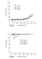
- Figure 2 is a graph of performance data of a gold catalyst tested with n-decane in the fluid stream.
- Figure 3 is a graph of performance data of a gold catalyst after thermal aging tested with n-decane in the fluid stream.
- Figure 4 is a graph of performance data of a gold catalyst tested without n-decane in the fluid stream.
- Figure 5 is a graph of performance data of a gold catalyst after thermal aging tested without n-decane in the fluid stream.
- Figure 6 is a graph of performance data of a gold catalyst when a second catalyst comprising an oxidation component capable of oxidizing hydrocarbons and an adsorbent component capable of adsorbing hydrocarbons is employed upstream (upstream bed volume 300 micro-liters) of the gold catalyst (gold catalyst bed volume 700 micro-liters) and n-decane is in the fluid stream.
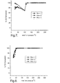
- Figure 7 is a graph of performance data of a gold catalyst after thermal aging when a second catalyst comprising an oxidation component capable of oxidizing hydrocarbons and an adsorbent component capable of adsorbing hydrocarbons is employed upstream (upstream bed volume 300 micro-liters) of the gold catalyst (gold catalyst bed volume 700 micro-liters) and n-decane is in the fluid stream.
- Figure 8 is a graph of performance data of another test of a gold catalyst when a second catalyst comprising an oxidation component capable of oxidizing hydrocarbons and an adsorbent component capable of adsorbing hydrocarbons is employed upstream (upstream bed volume 500 micro-liters) of the gold catalyst (gold catalyst bed volume 500 micro-liters) and n-decane is in the fluid stream.
- Figure 9 is a graph of performance data of yet another test of a gold catalyst after thermal aging when a second catalyst comprising an oxidation component capable of oxidizing hydrocarbons and an adsorbent component capable of adsorbing hydrocarbons is employed upstream (upstream bed volume 500 micro-liters) of the gold catalyst (gold catalyst bed volume 500 micro-liters) and n-decane is in the fluid stream.
- Figure 10 is a graph of performance data of a gold catalyst when a second catalyst comprising an oxidation component capable of oxidizing hydrocarbons and an adsorbent component capable of adsorbing hydrocarbons is in a physical mixture with gold catalyst and n-decane is in the fluid stream.
- Figure 11 is a graph of performance data of a gold catalyst when a second catalyst comprising an oxidation component capable of oxidizing hydrocarbons and an adsorbent component capable of adsorbing hydrocarbons is in a physical mixture with gold catalyst after thermal aging and n-decane is in the fluid stream.
- Figure 12 is a graph of performance data of gold catalyst when only a hydrocarbon adsorbent component is employed upstream of the gold catalyst.
- the exhaust treatment device 100 may include, but is not limited to, the following examples, catalytic converters, evaporative emissions devices, scrubbing devices (e.g., hydrocarbon, sulfur, and the like), particulate filters/traps, adsorbers/absorbers, non-thermal plasma reactors, and the like, as well as combinations comprising at least one of the foregoing devices.
- the exhaust treatment device 100 comprises a substrate 12 disposed within a retention material 14 forming a subassembly 16.
- a shell 18 is disposed around the subassembly 16.
- An end-cone 20 comprising a snorkel 22 having an opening 24 is in physical communication with shell 18. Opening 24 allows exhaust fluid communication with substrate 12.
- a catalyst may be disposed on/throughout substrate 12.
- Substrate 12 may comprise any material designed for use in a spark ignition or diesel engine environment and having the following characteristics:
- the substrate 12 may have any size or geometry, the size and geometry are preferably chosen to optimize surface area in the given exhaust emission control device design parameters.
- the substrate 12 may have a honeycomb geometry, with the combs through-channel having any multi-sided or rounded shape, with substantially square, triangular, pentagonal, hexagonal, heptagonal, or octagonal or similar geometries preferred due to ease of manufacturing and increased surface area.
- a retention material 14 that insulates the shell 18 from both the exhaust fluid temperatures and the exothermic catalytic reaction occurring within the catalyst substrate 12.
- the retention material 14, which enhances the structural integrity of the substrate by applying compressive radial forces about it, reducing its axial movement and retaining it in place, may be concentrically disposed around the substrate to form a retention material/substrate subassembly 16.
- the retention material 14 which may be in the form of a mat, particulates, or the like, may be an intumescent material (e.g., a material that comprises vermiculite component, i.e., a component that expands upon the application of heat), a non-intumescent material, or a combination thereof.
- intumescent material e.g., a material that comprises vermiculite component, i.e., a component that expands upon the application of heat
- non-intumescent material e.g., a material that comprises vermiculite component, i.e., a component that expands upon the application of heat
- non-intumescent material e.g., a non-intumescent material, or a combination thereof.
- ceramic materials e.g., ceramic fibers
- other materials such as organic and inorganic binders and the like, or combinations comprising at least one of the foregoing materials.
- Non-intumescent materials include materials such as those sold under the trademarks "NEXTEL” and “INTERAM 1101HT” by the “3M” Company, Minneapolis, Minnesota, or those sold under the trademark, "FIBERFRAX” and “CC-MAX” by the Unifrax Co., Niagara Falls, New York, and the like.
- Intumescent materials include materials sold under the trademark "INTERAM” by the “3M” Company, Minneapolis, Minnesota, as well as those intumescents which are also sold under the aforementioned "FIBERFRAX” trademark, as well as combinations thereof and others.
- the retention material/substrate subassembly 16 may be concentrically disposed within a shell 18.
- the choice of material for the shell 18 depends upon the type of exhaust fluid, the maximum temperature reached by the substrate 12, the maximum temperature of the exhaust fluid stream, and the like.
- Suitable materials for the shell 18 may comprise any material that is capable of resisting under-car salt, temperature, and corrosion.
- ferrous materials may be employed such as ferritic stainless steels.
- Ferritic stainless steels may include stainless steels such as, e.g., the 400 - Series such as SS-409, SS-439, and SS-441, with grade SS-409 generally preferred.
- End cone 20 (or alternatively an end cone(s), end plate(s), exhaust manifold cover(s), and the like), which may comprise similar materials as the shell, may be disposed at one or both ends of the shell.
- the end cone 20 (end plate or the like) is sealed to the shell to prevent leakage at the interface thereof.
- These components may be formed separately (e.g., molded or the like), or may be formed integrally with the housing using a methods such as, e.g., a spin forming, or the like.
- the shell may comprise two half shell components, also known as clamshells.
- the two half shell components are compressed together about the retention material/substrate subassembly, such that an annular gap preferably forms between the substrate and the interior surface of each half shell as the retention material becomes compressed about the substrate.
- the exhaust emission treatment device 100 may be manufactured by one or more techniques, and, likewise, the retention material/substrate subassembly 16 may be disposed within the shell 18 using one or more methods.
- the retention material/substrate subassembly 16 may be inserted into a variety of shells 18 using a stuffing cone.
- the stuffing cone is a device that compresses the retention material 14 concentrically about the substrate 12.
- the stuffing cone then stuffs the compressed retention material/substrate subassembly 16 into the shell, such that an annular gap preferably forms between the substrate 12 and the interior surface of the shell 18 as the retention material 14 becomes compressed about the substrate 12.
- the retention material 14 is in the form of particles (e.g., pellets, spheres, irregular objects, or the like) the substrate 12 may be stuffed into the shell 18 and the retention material may be disposed in the shell 18 between the substrate 12 and the shell 18.
- a catalyst may be disposed on and/or throughout (hereinafter "on") substrate 12.
- the catalyst may comprise any material capable of carbon monoxide oxidation.
- the catalyst preferably comprises gold.
- the gold catalyst may be supported on a support material. Additionally, the gold catalyst is sufficiently dispersed throughout the support material and has a particle size (taken along the major diameter (i.e., the longest diameter)) sufficient to be active for carbon monoxide oxidation at temperatures as low as -70°C.
- the gold catalyst may have a particle size of less than or equal to about 10 nanometers (nm).
- the gold catalyst is preferably "highly dispersed", i.e., the gold particles are substantially evenly distributed throughout the metal oxide (i.e., the concentration gradient of gold particles varies less than or equal to about 7 wt% throughout the substrate, based on a total weight of the gold particles disposed on the substrate).
- the gold catalyst may be prepared by any number of methods, e.g., impregnation of a support material with a salt of gold catalyst, followed by drying and reduction, and exchange of protons or other cations associated with the support material for cations of the gold catalyst, followed by washing, drying and reduction.
- the gold catalyst is preferably prepared by 1) coprecipitation of hydroxides or similar precursors to both support material and metal, followed by drying, calcination, and reduction; or 2) precipitationdeposition of gold onto a support material by initial neutralization of chloroauric acid with base, with concurrent partial or total substitution of hydroxide for chloride within the gold coordination sphere, followed by adsorption of the hydroxogold or chlorohydroxogold complexes onto the support material, followed by an effective sequence of washing and calcination steps to yield the catalyst.
- One method of making a gold catalyst may comprise mixing a support material (e.g., metal oxide) with an acidified solution comprising a gold compound to form a metal oxide/gold complex; contacting the metal oxide/gold complex with a base to form a metal oxide/gold hydroxide complex; washing the metal oxide/gold hydroxide complex with water; and transforming the metal oxide/gold hydroxide complex to the gold catalyst.
- the metal oxide/gold hydroxide complex is then treated, e.g., with heat, to transform the metal oxide/gold hydroxide complex to the gold catalyst.
- ligand as used herein includes functionalities such as counterion that are bound primarily through ionic interactions and functionalities whose bonds to gold are more covalent in character.
- the negatively charged ligand(s), if present, would contribute to the growth of gold particle size when the catalyst is exposed to elevated temperatures whereas the hydroxide ions do not. It is further believed that some or all of the hydroxide ions are removed through calcination.
- Useful gold compounds comprise gold in the +3 oxidation and one or more negatively charged ligands.
- useful gold compounds include HAuCl 4 , NaAuCl 4 , (AuBr 3 ) 2 , AuF 3 , and combinations comprising at least one of the foregoing compounds.
- the gold compound is HAuCl 4 .
- Useful support metal oxides include, but are not limited to, alumina, zirconia, titania, ceria, tin oxide, iron oxide (Fe 2 O 3 ), lead oxide, and combinations comprising at least one of the foregoing oxides. It is envisioned that silica and aluminosilicates may also be used. Preferably, the aluminosilicates are derivatized with reagents such as N,N,N-trimethyl-3-(trimethoxysilyl)-1-propanaminium chloride.
- the metal oxide is alumina, e.g., alpha ( ⁇ ) alumina, delta ( ⁇ ) alumina, gamma ( ⁇ ) alumina and/or theta ( ⁇ ) alumina.
- Useful bases are those capable of replacing the negatively charged ligand(s) with hydroxide ions.
- Exemplary strong bases include ammonium hydroxide, tetralkylammonium hydroxide, ammonium carbonate, tetraalkylammonium carbonate, sodium hydroxide, potassium hydroxide, cesium hydroxide, rubidium hydroxide, and combinations comprising at least one of the foregoing compounds.
- One method of making a gold catalyst comprises preparing a slurry of the metal oxide and adding an acidified solution of the gold compound to the slurry, preferably in a drop wise manner.
- the acidified solution of the gold compound comprises a gold compound or mixture of gold compounds and a solvent.
- the solvent may be water or an organic solvent capable of dissolving the gold compound.
- the concentration of gold in the solution affects the amount of gold adsorbed. Generally, increasing the concentration of gold in the solution results in increased gold adsorption.
- the pH of the acidified solution of gold is less than or equal to about 4.5.
- the pH of the acidified solution of gold is chosen such that the pH of the metal oxide slurry, after addition of the acidified gold solution, is less than or equal to the pH at zero charge of the metal oxide.
- the pH of the metal oxide slurry after addition of the acidified gold solution is about 1 to about 2 pH units less than the pH at zero charge of the metal oxide.
- the gold containing slurry is allowed to stir for a time sufficient to permit adsorption of the gold compound onto the metal oxide.
- the amount of time spent stirring is dependent upon, for example, the identity of the gold compound as well as the identity of the metal oxide.
- the amount of stir time may be about 1 hour and the alumina is observed to develop a yellowish color.
- the metal oxide/gold complex is separated from a majority of the slurry liquid by a solid/liquid separation technique such as filtration, centrifugation, or simple decantation.
- the metal oxide/gold complex may then be washed with water, preferably deionized water.
- the metal oxide/gold complex is then contacted with a base to from a metal oxide/gold hydroxide complex and the pH of the resulting solution is monitored. Base is added until the solution pH reaches a constant level.
- the metal oxide/gold hydroxide complex is then separated from the solution and preferably washed with water. Preferably, the water is deionized.
- the metal oxide/gold hydroxide complex may then be dried in an oven or exposed to the ambient atmosphere to dry. Drying may be performed in addition to the calcining described below or drying and calcinations may be performed together.
- the metal oxide/gold hydroxide complex is calcined at a sufficient temperature and sufficient time to fix the gold onto the support material such that the gold does not leach into wash water intended to remove chloride ion, and to partially reduce gold into a mixed valent state, including elemental gold and oxidized gold.
- Suitable calcination temperatures are less than or equal to about 600°C, preferably less than or equal to about 400°C. Additionally, calcination temperatures are greater than or equal to about 50°C, preferably greater than or equal to about 100°C, and more preferably greater than or equal to about 200°C.
- the calcination may be conducted for about 0.5 hours to about 6 hours, preferably about 1 hour to about 5 hours, and more preferably about 2 hours to about 4 hours.
- Calcination results in the formation of a gold catalyst.
- calcination may not be necessary when the metal oxide/gold hydroxide complex is located in reaction environments having temperatures greater than or equal to about 50°C.
- the gold catalyst may be formed from the metal oxide/adsorbed gold complex in situ.
- the method comprises preparing a gold solution by reacting a chloroauric acid (e.g., HAuCl 4 ) slowly with a solution of a strong base (e.g., sodium hydroxide) resulting in an intermediate gold complex (or mixture of complexes) that is then precipitated or deposited onto a support material (e.g., alumina), which may be either in the form of an aqueous or non-aqueous slurry or granules mixed with a solvent, followed by washing, calcination and, optionally, washing again.
- a support material e.g., alumina
- the solvent is water.
- the gold-alumina mixture is washed once after precipitation/deposition, then calcined at a temperature of about 100°C to about 600°C, with a temperature of about 350°C to about 450°C preferred, and then washed again repeatedly to remove chloride from the catalyst.
- the catalyst may be calcined again after essentially all of the chloride is washed away.
- the calcination are performed under humid conditions in an oxidizing atmosphere.
- the gold solution may be obtained by reacting HAuCl 4 , having a pH less than or equal to about 2, slowly with sodium hydroxide until the pH of the solution has a pH of about 6 to about 8, with a neutral pH of 7 preferred.
- a support material e.g., alumina, may be added to the solution and heated at a temperature sufficient and for a sufficient duration for the gold to adsorb onto the support material, e.g., at a temperature of about 75°C to 125°C for about 1 hr.
- the metal oxide/gold precipitate may be separated from a majority of the solution liquid by a solid/liquid separation technique such as filtration, centrifugation, or simple decantation.
- the metal oxide/gold complex may then be washed with water, preferably deionized water to remove Cl - and Na + ions.
- acetone may than be used to wash the precipitate.
- the precipitate is then dried and calcined at a sufficient temperature and sufficient time to fix the gold onto the support material.
- Suitable calcination temperatures are less than or equal to about 600°C, preferably less than or equal to about 400°C. Additionally, calcination temperatures are greater than or equal to about 50°C, preferably greater than or equal to 100°C, and more preferably greater than or equal to about 200°C.
- the calcination may be conducted for about 0.5 hours to about 6 hours, preferably about 1 hour to about 5 hours, and more preferably about 2 hours to about 4 hours.
- the gold catalyst may be prepared by any of the above methods to obtain a gold catalyst capable of being active for carbon monoxide oxidation at temperatures less than or equal to about 100°C.
- the gold catalyst has a metal loading (e.g., gold loading) of greater than or equal to about 0.1 weight percent (wt%), preferably greater than or equal to about 0.5 wt%, and more preferably greater than or equal to about 0.75 wt%, based on the total weight of the catalyst and support material.
- the gold catalyst may have a metal loading of less than or equal to about 7 wt%, preferably less than or equal to about 5 wt%, and more preferably less than or equal to about 2.5 wt%, based on the total weight of the catalyst and support material.
- the gold catalyst is active for carbon monoxide oxidation.
- gold catalysts may be very readily deactivated, i.e., poisoned, by hydrocarbons, e.g., n-decane. Since exposing the gold catalyst to hydrocarbons may deactivate it, the gold catalyst is preferably protected from hydrocarbons.
- the gold catalyst may be protected by a second catalyst disposed in a physical mixture with the gold catalyst, a second catalyst disposed upstream of the gold catalyst in an exhaust system, or a second catalyst disposed both in physical mixture with the gold catalyst and disposed upstream of the gold catalyst in an exhaust system.
- the second catalyst comprises an adsorbent material (e.g., ⁇ -zeolite), a support material, (e.g., theta alumina ( ⁇ -Al 2 O 3 )), and an oxidation catalyst (e.g., platinum),wherein the adsorbent material is capable of adsorbing hydrocarbons and the oxidation catalyst is active for the oxidation of hydrocarbons.
- an adsorbent material e.g., ⁇ -zeolite
- a support material e.g., theta alumina ( ⁇ -Al 2 O 3 )
- an oxidation catalyst e.g., platinum
- the adsorbent material comprises a material capable of adsorbing or trapping hydrocarbons.
- the adsorbent material may include, but is not limited to, zeolites that are capable of trapping hydrocarbons at low temperatures (i.e., less than or equal to about 250°C, with less than or equal to about 150°C more preferred) and releasing those hydrocarbons at higher temperatures where they may oxidize more readily.
- the zeolite may be characterized in that it maintains crystalline structure over extended operation at temperatures in the range of 750°C to about 850°C in air, has an average pore size (taken along the major diameter (i.e., the longest diameter)) of greater than or equal to about 0.6 nanometers (nm), and a has a Si/Al ratio of preferably about 30 to about 100.
- suitable zeolites are beta zeolite, ultra-stable Y zeolite, and UTD-1 zeolite, with beta and Y being preferred.
- more than one type of zeolite may be used.
- a blend of beta and Y zeolites may be used, or two or more zeolites each having a different range of pore sizes may be used.
- the support material may comprise an inorganic oxide, which may improve adhesion of the zeolite to a carrier substrate in, for example, a washcoat process or act as a binder for catalysts formed without a carrier substrate.
- the inorganic oxide e.g., alumina and titania
- alumina and titania may aid in the oxidation of carbon monoxide.
- both alumina and titania may tend to also promote the oxidation of hydrocarbons.
- the alumina may be in the gamma, delta, or theta forms.
- the titania is preferably in the anatase phase.
- oxidation catalyst of the second catalyst is active for the oxidation of hydrocarbons.
- oxidation catalyst of the second catalyst contains palladium or platinum.
- suitable oxidation catalyst precursor compounds include, but is not limited to, tetraamine platinum hydroxide, platinum nitrate, platinum sulfite, platinum dicarbonyl dichloride, dinitrodiamino platinum, palladium nitrate, diamminepalladium hydroxide, tetraamminepalladium chloride, palladium citrate, rhodium trichloride, hexaamminerhodium chloride, rhodium carbonylchloride, rhodium trichloride hydrate, rhodium nitrate, hexachloroiridate (IV) acid, hexachloroiridate (III) acid, dichlorodhydroiridate (III) acid, ammonium hexachloroiridate (III) acid, ammonium hexachloroiri
- the second catalyst comprising may be in a physical mixture with the gold catalyst.
- the second catalyst may be added to the slurry used in making the gold catalyst.
- a ratio of the volume of catalyst metal used for the second catalyst, e.g., platinum, to the volume of gold catalyst used in the first catalyst is less than or equal to about 2, with a ratio of less than or equal to about 1 more preferred.
- the ratio of the second metal catalyst volume to first metal catalyst volume is greater than or equal to about 1:12.5.
- the second catalyst may, additionally or alternatively, be disposed upstream of the gold catalyst.
- the term upstream as used herein has its ordinary meaning, and is used herein to generally denote the position of a component relative to the other component in a system, for example, an exhaust system.
- hydrocarbons in the exhaust system may be trapped and oxidized, thereby substantially reducing/eliminating hydrocarbons in the exhaust stream.
- the gold catalyst may be used in the reduction of carbon monoxide that may be present in the exhaust fluid. Since the hydrocarbons are substantially reduced/eliminated, the gold catalyst may be protected from being deactivated.
- the gold catalyst having a second catalyst disposed upstream, or disposed in a physical mixture therewith, or a combination comprising at least one of the foregoing may have an extended life, i.e., a greater activity for a longer period of time, compared to a gold catalyst that is not protected from hydrocarbons.
- controlling the space velocity of exhaust fluid through the exhaust treatment device comprising the gold catalyst may further protect the gold catalyst.
- the space velocity may be less than or equal to about 250,000 hr -1 , with a space velocity of less than or equal to about 37,000 hr -1 preferred, and a space velocity of less than or equal to about 25,000 hr -1 more preferred.
- a precipitation/deposition approach was used to make the gold catalyst used herein.
- An exemplary procedure for making the gold catalyst is as follows:
- the obtained solution was heated with 5 g of ⁇ -Al 2 O 3 (pre-calcined in a dry air flow at 750°C for 4 hr; S BET is 200 m 2 /g, pore volume is 1.15 ml/g, particle size 0.25 millimeters (mm) to 0.5 mm in a sealed, shaken, temperature controlled reactor at 70°C for 2 hr.
- the solution was decanted and a precipitate was washed by vigorous agitation with some portions of distilled water (0.8 liter, 14 times) at 35°C to remove chlorine ions (Cl - ) and sodium ions (Na + ) and then filtered using a Buchner funnel, washed with a small volume of acetone (5 ml to 10 ml) and dried at room temperature and 0.02 Torr for 12 hours. A dried sample was heated in air to 400°C during 2 hours and then calcined at this temperature for another 4 hours. The content of gold in the sample prepared was 1.2% by weight, as measured by ICP.
- the linear velocity of gas flow was about 0.06 meters per second (m/s).
- the gold catalyst diluted with quartz particles of about 1 millimeter (mm) to about 2 mm in size was loaded into the reactor.
- a second catalyst (as described above, and in, for example, U.S. Patent No. 6,127,300 to Kharas et al. and U.S. Patent No.5,897,846 to Kharas et al., which are herein incorporated in their entirety.) granular bed was situated upstream of the gold catalyst bed.
- the gold and the second catalyst beds were divided by means of a pure quartz bed.
- the initial reaction mixture for testing had the following composition: 0.1 % carbon monoxide (CO), 10% water (H 2 O), 14% oxygen (O 2 ), 0.075% n-decane (n-C 10 H 22 ), and nitrogen as a balance gas. Temperature was linearly varied from 30°C to 300°C with the heating rate of 10°C/min controlled by a personal computer. Three sequential heating - cooling cycles (runs) were carried out during a single testing procedure.
- the thermal aging procedure was performed at 700°C for 4 hours; the flowing gas mixture (a feeding blend) had the following composition: 10% water vapor, air as a balance gas. After the thermal aging procedure, three subsequent cycles of the catalytic activity measurements were repeated.
- the gold catalyst was tested fresh, three times, using the above described synthetic gas mixture, which includes n-decane. As is shown in Figure 2, performance is substantially poorer in the second temperature rise and even slightly worse in the third temperature rise. In other words, the percent conversion of carbon monoxide was lower at the second temperature rise and the third temperature rise compared to the first temperature rise.
- Figure 6 shows the results of a 300 micro-liter second catalyst granular bed of a second catalyst (Pt-zeolite-alumina diesel oxidation catalyst) was situated upstream of a 700 micro-liter bed of the gold catalyst.
- This dual bed system was then tested with the fully formulated model gas blend, including n-decane.
- low-temperature CO oxidation activity was observed, i.e., CO oxidation activity was observed at temperatures below 100°C. Additionally, the first temperature rise had the worst, not the best, performance.
- the CO oxidation activity shown in Figure 6 is a little worse than that of Figure 4, but much better than Figure 2.
- the slightly inferior low temperature CO oxidation results of Figure 5, compared to Figure 3, may be attributed to the fact that the gold bed is small than in Figure 4.
- the total bed volume was held constant, as such the gold bed was 30% smaller in Figure 6 than in Figure 4.
- Figure 7 shows the results, after thermal aging, of a test 300 micro-liter second catalyst granular bed of a second catalyst (Pt-zeolite-alumina diesel oxidation catalyst) was situated upstream of a 700 micro-liter bed of the gold catalyst.
- a second catalyst Pt-zeolite-alumina diesel oxidation catalyst
- the second catalyst contained only calcined beta zeolite, rather than containing Pt/( ⁇ -Al 2 O 3 + ⁇ -zeolite), as a guard bed, the results obtain were even worse than in the absence of the guard bed. Compare Figure 12 to Figure 2. Without being bound by theory, this observation may be attributed to the fact that the zeolite may have cracked decane to unsaturated species that very effectively poisoned the gold catalyst.
- an exhaust treatment system comprising a gold catalyst and a second catalyst in a physical mixture with the gold catalyst or located upstream of the gold catalyst has a carbon monoxide conversion greater than or equal to about 45% at temperatures of about 25°C to about 100°C after thermal aging (i.e., the gold catalyst and the second catalyst are exposed to temperatures of up to about 800°C for a period of time up to about 4 hours). More particularly, at temperatures of about 50°C to about 75°C, a CO conversion is greater than or equal to 50%, with greater than or equal to 70% preferred. Additionally, at temperatures greater than about or equal to about 125°C, the exhaust treatment system has a carbon monoxide conversion system greater than or equal to about 90% conversion, with 100% conversion preferred.
- embodiments disclosed herein allow for carbon monoxide oxidation at temperatures below 100°C by employing a second catalyst to protect the gold catalyst from hydrocarbon deactivation.
- a reduction in carbon monoxide emissions may be realized, since greater than 50% of the allowed carbon monoxide emissions may occur during start-up conditions, i.e., temperatures below 100°C.
- greater than or equal to 50% CO may be converter to CO 2 at temperatures less than or equal to about 100°C in an atmosphere comprising a hydrocarbon at a space velocity less than or equal to 50,000 hr -1 .
- the disclosed gold catalyst with second protection catalyst may be used in any application where carbon monoxide oxidation at temperatures less than or equal to about 100°C is desirable.
- the catalyst system comprising the gold catalyst and second protection cold catalyst may be used in the automotive industry for exhaust gas treatment; and in home use, such as in a purification system for treatment of household air, which may be incorporated as part of a home heating system.
Landscapes
- Chemical & Material Sciences (AREA)
- Engineering & Computer Science (AREA)
- Chemical Kinetics & Catalysis (AREA)
- Organic Chemistry (AREA)
- Materials Engineering (AREA)
- Oil, Petroleum & Natural Gas (AREA)
- Analytical Chemistry (AREA)
- General Chemical & Material Sciences (AREA)
- Environmental & Geological Engineering (AREA)
- Biomedical Technology (AREA)
- Health & Medical Sciences (AREA)
- Combustion & Propulsion (AREA)
- Crystallography & Structural Chemistry (AREA)
- Catalysts (AREA)
- Exhaust Gas Treatment By Means Of Catalyst (AREA)
- Exhaust Gas After Treatment (AREA)
Applications Claiming Priority (2)
| Application Number | Priority Date | Filing Date | Title |
|---|---|---|---|
| US794789 | 2004-03-05 | ||
| US10/794,789 US20050197244A1 (en) | 2004-03-05 | 2004-03-05 | Exhaust treatment system and catalyst system |
Related Child Applications (1)
| Application Number | Title | Priority Date | Filing Date |
|---|---|---|---|
| EP09004800 Division | 2009-04-01 |
Publications (3)
| Publication Number | Publication Date |
|---|---|
| EP1570895A2 true EP1570895A2 (fr) | 2005-09-07 |
| EP1570895A3 EP1570895A3 (fr) | 2007-01-03 |
| EP1570895B1 EP1570895B1 (fr) | 2010-01-06 |
Family
ID=34750645
Family Applications (1)
| Application Number | Title | Priority Date | Filing Date |
|---|---|---|---|
| EP05075504A Expired - Lifetime EP1570895B1 (fr) | 2004-03-05 | 2005-03-01 | Système pour le traitement des gaz d'échappement et système catalytique |
Country Status (4)
| Country | Link |
|---|---|
| US (2) | US20050197244A1 (fr) |
| EP (1) | EP1570895B1 (fr) |
| AT (1) | ATE454205T1 (fr) |
| DE (1) | DE602005018700D1 (fr) |
Cited By (9)
| Publication number | Priority date | Publication date | Assignee | Title |
|---|---|---|---|---|
| GB2444125A (en) * | 2006-11-27 | 2008-05-28 | Nanostellar Inc | Engine exhaust catalysts containing palladium-gold |
| US7534738B2 (en) | 2006-11-27 | 2009-05-19 | Nanostellar, Inc. | Engine exhaust catalysts containing palladium-gold |
| US7709414B2 (en) | 2006-11-27 | 2010-05-04 | Nanostellar, Inc. | Engine exhaust catalysts containing palladium-gold |
| RU2388532C1 (ru) * | 2008-10-27 | 2010-05-10 | Институт Катализа Им. Г.К. Борескова Сибирского Отделения Российской Академии Наук | Способ приготовления катализатора для обезвреживания газовых выбросов (варианты) |
| WO2011106213A1 (fr) * | 2010-02-24 | 2011-09-01 | Corning Incorporated | Catalyseurs à l'or nanométriques pour oxydation de co et réactions de déplacement gaz-eau |
| US8258070B2 (en) | 2006-11-27 | 2012-09-04 | WGCH Technology Limited | Engine exhaust catalysts containing palladium-gold |
| US8551411B2 (en) | 2008-05-09 | 2013-10-08 | Johnson Matthey Public Limited Company | Exhaust system for lean-burn internal combustion engine comprising Pd-Au-alloy catalyst |
| CN105238172A (zh) * | 2015-11-13 | 2016-01-13 | 杨超 | 一种耐盐碱腐蚀的绝缘子 |
| CN105255276A (zh) * | 2015-11-13 | 2016-01-20 | 杨超 | 一种耐盐碱腐蚀的电力行业专用涂料 |
Families Citing this family (16)
| Publication number | Priority date | Publication date | Assignee | Title |
|---|---|---|---|---|
| US7169376B2 (en) * | 2004-06-10 | 2007-01-30 | Chevron U.S.A. Inc. | Method for making hydrogen using a gold containing water-gas shift catalyst |
| US7576031B2 (en) * | 2006-06-09 | 2009-08-18 | Basf Catalysts Llc | Pt-Pd diesel oxidation catalyst with CO/HC light-off and HC storage function |
| US8071504B2 (en) | 2008-12-19 | 2011-12-06 | Caterpillar Inc. | Exhaust system having a gold-platinum group metal catalyst |
| US8246923B2 (en) * | 2009-05-18 | 2012-08-21 | Umicore Ag & Co. Kg | High Pd content diesel oxidation catalysts with improved hydrothermal durability |
| US8557203B2 (en) * | 2009-11-03 | 2013-10-15 | Umicore Ag & Co. Kg | Architectural diesel oxidation catalyst for enhanced NO2 generator |
| JP5664918B2 (ja) * | 2011-04-08 | 2015-02-04 | トヨタ自動車株式会社 | 排ガス浄化用触媒 |
| US8980209B2 (en) | 2012-12-12 | 2015-03-17 | Basf Corporation | Catalyst compositions, catalytic articles, systems and processes using protected molecular sieves |
| CA2892683A1 (fr) | 2012-12-12 | 2014-06-19 | Basf Corporation | Compositions de catalyseurs, articles catalytiques, systemes et procedes utilisant des tamis moleculaires a grosses particules |
| US9511355B2 (en) | 2013-11-26 | 2016-12-06 | Clean Diesel Technologies, Inc. (Cdti) | System and methods for using synergized PGM as a three-way catalyst |
| US9511350B2 (en) | 2013-05-10 | 2016-12-06 | Clean Diesel Technologies, Inc. (Cdti) | ZPGM Diesel Oxidation Catalysts and methods of making and using same |
| US20140274662A1 (en) | 2013-03-15 | 2014-09-18 | Cdti | Systems and Methods for Variations of ZPGM Oxidation Catalysts Compositions |
| US20150005159A1 (en) * | 2013-06-26 | 2015-01-01 | Cdti | Optimization of Zero-PGM Metal Loading on Metallic Substrates |
| US9545626B2 (en) | 2013-07-12 | 2017-01-17 | Clean Diesel Technologies, Inc. | Optimization of Zero-PGM washcoat and overcoat loadings on metallic substrate |
| US9511358B2 (en) | 2013-11-26 | 2016-12-06 | Clean Diesel Technologies, Inc. | Spinel compositions and applications thereof |
| JP6048459B2 (ja) * | 2014-08-08 | 2016-12-21 | トヨタ自動車株式会社 | NOx吸蔵還元型触媒及びその製造方法 |
| CN116289802B (zh) * | 2023-02-22 | 2023-09-22 | 南京威铁网络科技有限公司 | 一种用于水利工程的闸门拉杆起吊机构及其应用方法 |
Citations (1)
| Publication number | Priority date | Publication date | Assignee | Title |
|---|---|---|---|---|
| US5897846A (en) | 1997-01-27 | 1999-04-27 | Asec Manufacturing | Catalytic converter having a catalyst with noble metal on molecular sieve crystal surface and method of treating diesel engine exhaust gas with same |
Family Cites Families (18)
| Publication number | Priority date | Publication date | Assignee | Title |
|---|---|---|---|---|
| JPS5912115A (ja) * | 1982-07-13 | 1984-01-21 | Samukomu Electron Kk | 自動車排ガス浄化用触媒 |
| US5127300A (en) * | 1991-02-19 | 1992-07-07 | Silverman Martin D | Pick holder for a stringed musical instrument |
| US6087295A (en) * | 1992-12-14 | 2000-07-11 | Asec Manufacturing | Reduction of NOx in the exhaust gases from internal combustion engines containing excess oxygen |
| JP3430422B2 (ja) * | 1992-12-14 | 2003-07-28 | 財団法人石油産業活性化センター | 窒素酸化物接触還元用触媒 |
| TW267951B (fr) * | 1993-09-24 | 1996-01-11 | Ikemukyatto Kk N | |
| JPH08173768A (ja) * | 1994-12-26 | 1996-07-09 | Sekiyu Sangyo Kasseika Center | 窒素酸化物の接触還元方法 |
| ATE216280T1 (de) * | 1995-01-20 | 2002-05-15 | Engelhard Corp | Vorrichtung zur schadstoffentfernung aus umgebungsluft in der motorhaube eines fahrzeuges |
| US5849255A (en) | 1995-06-07 | 1998-12-15 | Asec Manufacturing | Treatment of diesel exhaust gas using zeolite catalyst |
| ZA963235B (en) * | 1995-06-15 | 1996-10-25 | Engelhard Corp | Diesel exhaust stream treating catalyst and method of use |
| IT1283143B1 (it) * | 1996-07-12 | 1998-04-07 | Indena Spa | Metodo di estrazione del licopene ed estratti che lo contengono |
| US5948377A (en) * | 1996-09-04 | 1999-09-07 | Engelhard Corporation | Catalyst composition |
| BG62687B1 (bg) * | 1997-05-15 | 2000-05-31 | "Ламан-Консулт"Оод | Златен катализатор за окисление на въглероден оксид и въглеводороди, редуциране на азотни оксиди иразлагане на озон |
| JPH11267504A (ja) * | 1998-03-24 | 1999-10-05 | Ngk Insulators Ltd | 排ガス浄化用触媒体とそれを用いた排ガス浄化システム |
| KR100284936B1 (ko) * | 1998-12-31 | 2001-04-02 | 김충섭 | 촉매 활성 귀금속 담지 제올라이트계 탈질 촉매의 제조 방법 |
| JP4642978B2 (ja) * | 2000-08-08 | 2011-03-02 | 株式会社キャタラー | 排ガス浄化用触媒 |
| US6482368B2 (en) * | 2000-12-19 | 2002-11-19 | Delphi Technologies, Inc. | Non-thermal plasma reactor for lower power consumption |
| TWI261533B (en) * | 2002-12-31 | 2006-09-11 | Ind Tech Res Inst | Nano-gold catalyst and preparation of nano-gold catalyst |
| US20050129589A1 (en) * | 2003-12-16 | 2005-06-16 | Di Wei | Multi-layered photocatalyst/thermocatalyst for improving indoor air quality |
-
2004
- 2004-03-05 US US10/794,789 patent/US20050197244A1/en not_active Abandoned
-
2005
- 2005-03-01 EP EP05075504A patent/EP1570895B1/fr not_active Expired - Lifetime
- 2005-03-01 AT AT05075504T patent/ATE454205T1/de not_active IP Right Cessation
- 2005-03-01 DE DE602005018700T patent/DE602005018700D1/de not_active Expired - Lifetime
-
2008
- 2008-06-24 US US12/144,761 patent/US7824639B2/en not_active Expired - Fee Related
Patent Citations (2)
| Publication number | Priority date | Publication date | Assignee | Title |
|---|---|---|---|---|
| US5897846A (en) | 1997-01-27 | 1999-04-27 | Asec Manufacturing | Catalytic converter having a catalyst with noble metal on molecular sieve crystal surface and method of treating diesel engine exhaust gas with same |
| US6127300A (en) | 1997-01-27 | 2000-10-03 | Asec Manufacturing General Partnership | Process for making a catalyst with noble metal on molecular sieve crystal surface |
Cited By (15)
| Publication number | Priority date | Publication date | Assignee | Title |
|---|---|---|---|---|
| US8258070B2 (en) | 2006-11-27 | 2012-09-04 | WGCH Technology Limited | Engine exhaust catalysts containing palladium-gold |
| GB2444126A (en) * | 2006-11-27 | 2008-05-28 | Nanostellar Inc | Engine exhaust catalysts containing palladium-gold |
| US7517826B2 (en) | 2006-11-27 | 2009-04-14 | Nanostellar, Inc. | Engine exhaust catalysts containing zeolite and zeolite mixtures |
| US7534738B2 (en) | 2006-11-27 | 2009-05-19 | Nanostellar, Inc. | Engine exhaust catalysts containing palladium-gold |
| GB2444126B (en) * | 2006-11-27 | 2009-05-27 | Nanostellar Inc | Engine exhaust catalysts containing palladium-gold |
| US7709414B2 (en) | 2006-11-27 | 2010-05-04 | Nanostellar, Inc. | Engine exhaust catalysts containing palladium-gold |
| GB2444125A (en) * | 2006-11-27 | 2008-05-28 | Nanostellar Inc | Engine exhaust catalysts containing palladium-gold |
| US7745367B2 (en) | 2006-11-27 | 2010-06-29 | Nanostellar, Inc. | Engine exhaust catalysts containing palladium-gold |
| GB2444125B (en) * | 2006-11-27 | 2010-07-21 | Nanostellar Inc | Engine exhaust catalysts containing palladium-gold |
| US8551411B2 (en) | 2008-05-09 | 2013-10-08 | Johnson Matthey Public Limited Company | Exhaust system for lean-burn internal combustion engine comprising Pd-Au-alloy catalyst |
| RU2388532C1 (ru) * | 2008-10-27 | 2010-05-10 | Институт Катализа Им. Г.К. Борескова Сибирского Отделения Российской Академии Наук | Способ приготовления катализатора для обезвреживания газовых выбросов (варианты) |
| WO2011106213A1 (fr) * | 2010-02-24 | 2011-09-01 | Corning Incorporated | Catalyseurs à l'or nanométriques pour oxydation de co et réactions de déplacement gaz-eau |
| US9139433B2 (en) | 2010-02-24 | 2015-09-22 | Corning Incorporated | Gold catalysts for co oxidation and water gas shift reactions |
| CN105238172A (zh) * | 2015-11-13 | 2016-01-13 | 杨超 | 一种耐盐碱腐蚀的绝缘子 |
| CN105255276A (zh) * | 2015-11-13 | 2016-01-20 | 杨超 | 一种耐盐碱腐蚀的电力行业专用涂料 |
Also Published As
| Publication number | Publication date |
|---|---|
| US20050197244A1 (en) | 2005-09-08 |
| US20080317653A1 (en) | 2008-12-25 |
| ATE454205T1 (de) | 2010-01-15 |
| US7824639B2 (en) | 2010-11-02 |
| EP1570895A3 (fr) | 2007-01-03 |
| DE602005018700D1 (de) | 2010-02-25 |
| EP1570895B1 (fr) | 2010-01-06 |
Similar Documents
| Publication | Publication Date | Title |
|---|---|---|
| US7824639B2 (en) | Exhaust treatment system and catalyst system | |
| EP2069052B1 (fr) | Catalyseurs pour réduire le nox compris dans un flux de gaz d'échappement, et procédés de préparation | |
| KR101496916B1 (ko) | 질소 산화물 제거용 촉매 및 그것을 사용한 질소 산화물 제거 방법 | |
| CN107405606B (zh) | 柴油机氧化催化剂 | |
| EP1541220B1 (fr) | Dispositif de traitement de gaz d'échappement | |
| US7189376B2 (en) | Multi-zoned catalyst and trap | |
| US7563744B2 (en) | Catalyst featuring silicone dioxide based support material for the purification of exhaust gases | |
| US5948723A (en) | Layered catalyst composite | |
| KR0131379B1 (ko) | 팔라듐을 함유하고 세리아로 지지된 백금 촉매 및 이것을 함유하는 촉매 조립체 | |
| KR101202162B1 (ko) | 적층 배기 처리 촉매 | |
| KR101529416B1 (ko) | 배기 가스 정화용 촉매 | |
| US4650782A (en) | Lead-tolerant catalyst for treating exhaust gas in the presence of SO2 | |
| KR20010033611A (ko) | 내연기관 동력의 차량용 촉매 전환기 시스템 | |
| JP2004508186A (ja) | 排気ガス浄化用触媒組成物 | |
| EP2117707A1 (fr) | Catalyseurs de zéolite cha cuivre | |
| CN102015536A (zh) | 贱金属和贱金属改性的柴油氧化催化剂 | |
| JP2003320252A (ja) | 排気ガス浄化触媒及びその製造方法 | |
| CN112912173A (zh) | 贱金属掺杂的氧化锆催化剂载体材料 | |
| WO2020257220A1 (fr) | Système de catalyseur à 3 voies pour automobile contenant un catalyseur de tuyau d'échappement | |
| JP2002001124A (ja) | 排気ガス浄化用触媒および排気ガス浄化方法 | |
| KR20230143152A (ko) | 자동차 가솔린 적용으로부터의 암모니아 배출물을 감소시키기 위한 배기가스 처리 시스템 | |
| US20240189771A1 (en) | Platinum-containing three-way catalyst for close-coupled engine application | |
| US6750168B2 (en) | High-temperature aging tolerance catalyzed adsorber system for treating internal combustion engine exhaust gas | |
| KR20230079392A (ko) | 유도 가열식 NOx 흡착제 | |
| EP1102629A1 (fr) | Systeme ameliore d'adsorbeur catalyse pour traiter des gaz d'echappement de moteur a combustion interne et son procede de fabrication |
Legal Events
| Date | Code | Title | Description |
|---|---|---|---|
| PUAI | Public reference made under article 153(3) epc to a published international application that has entered the european phase |
Free format text: ORIGINAL CODE: 0009012 |
|
| AK | Designated contracting states |
Kind code of ref document: A2 Designated state(s): AT BE BG CH CY CZ DE DK EE ES FI FR GB GR HU IE IS IT LI LT LU MC NL PL PT RO SE SI SK TR |
|
| AX | Request for extension of the european patent |
Extension state: AL BA HR LV MK YU |
|
| RTI1 | Title (correction) |
Free format text: ECHAUST TREATMENT SYSTEM AND CATALYST SYSTEM |
|
| PUAL | Search report despatched |
Free format text: ORIGINAL CODE: 0009013 |
|
| AK | Designated contracting states |
Kind code of ref document: A3 Designated state(s): AT BE BG CH CY CZ DE DK EE ES FI FR GB GR HU IE IS IT LI LT LU MC NL PL PT RO SE SI SK TR |
|
| AX | Request for extension of the european patent |
Extension state: AL BA HR LV MK YU |
|
| 17P | Request for examination filed |
Effective date: 20070703 |
|
| AKX | Designation fees paid |
Designated state(s): AT BE BG CH CY CZ DE DK EE ES FI FR GB GR HU IE IS IT LI LT LU MC NL PL PT RO SE SI SK TR |
|
| RAP1 | Party data changed (applicant data changed or rights of an application transferred) |
Owner name: UMICORE AG & CO. KG |
|
| 17Q | First examination report despatched |
Effective date: 20080701 |
|
| GRAP | Despatch of communication of intention to grant a patent |
Free format text: ORIGINAL CODE: EPIDOSNIGR1 |
|
| RTI1 | Title (correction) |
Free format text: EXHAUST TREATMENT SYSTEM AND CATALYST SYSTEM |
|
| GRAS | Grant fee paid |
Free format text: ORIGINAL CODE: EPIDOSNIGR3 |
|
| GRAA | (expected) grant |
Free format text: ORIGINAL CODE: 0009210 |
|
| AK | Designated contracting states |
Kind code of ref document: B1 Designated state(s): AT BE BG CH CY CZ DE DK EE ES FI FR GB GR HU IE IS IT LI LT LU MC NL PL PT RO SE SI SK TR |
|
| REG | Reference to a national code |
Ref country code: GB Ref legal event code: FG4D |
|
| REG | Reference to a national code |
Ref country code: CH Ref legal event code: EP |
|
| REG | Reference to a national code |
Ref country code: IE Ref legal event code: FG4D |
|
| REF | Corresponds to: |
Ref document number: 602005018700 Country of ref document: DE Date of ref document: 20100225 Kind code of ref document: P |
|
| REG | Reference to a national code |
Ref country code: NL Ref legal event code: VDEP Effective date: 20100106 |
|
| PG25 | Lapsed in a contracting state [announced via postgrant information from national office to epo] |
Ref country code: SI Free format text: LAPSE BECAUSE OF FAILURE TO SUBMIT A TRANSLATION OF THE DESCRIPTION OR TO PAY THE FEE WITHIN THE PRESCRIBED TIME-LIMIT Effective date: 20100106 |
|
| LTIE | Lt: invalidation of european patent or patent extension |
Effective date: 20100106 |
|
| PG25 | Lapsed in a contracting state [announced via postgrant information from national office to epo] |
Ref country code: AT Free format text: LAPSE BECAUSE OF FAILURE TO SUBMIT A TRANSLATION OF THE DESCRIPTION OR TO PAY THE FEE WITHIN THE PRESCRIBED TIME-LIMIT Effective date: 20100106 |
|
| PG25 | Lapsed in a contracting state [announced via postgrant information from national office to epo] |
Ref country code: ES Free format text: LAPSE BECAUSE OF FAILURE TO SUBMIT A TRANSLATION OF THE DESCRIPTION OR TO PAY THE FEE WITHIN THE PRESCRIBED TIME-LIMIT Effective date: 20100417 Ref country code: IS Free format text: LAPSE BECAUSE OF FAILURE TO SUBMIT A TRANSLATION OF THE DESCRIPTION OR TO PAY THE FEE WITHIN THE PRESCRIBED TIME-LIMIT Effective date: 20100506 Ref country code: NL Free format text: LAPSE BECAUSE OF FAILURE TO SUBMIT A TRANSLATION OF THE DESCRIPTION OR TO PAY THE FEE WITHIN THE PRESCRIBED TIME-LIMIT Effective date: 20100106 Ref country code: PT Free format text: LAPSE BECAUSE OF FAILURE TO SUBMIT A TRANSLATION OF THE DESCRIPTION OR TO PAY THE FEE WITHIN THE PRESCRIBED TIME-LIMIT Effective date: 20100506 Ref country code: LT Free format text: LAPSE BECAUSE OF FAILURE TO SUBMIT A TRANSLATION OF THE DESCRIPTION OR TO PAY THE FEE WITHIN THE PRESCRIBED TIME-LIMIT Effective date: 20100106 |
|
| PG25 | Lapsed in a contracting state [announced via postgrant information from national office to epo] |
Ref country code: FI Free format text: LAPSE BECAUSE OF FAILURE TO SUBMIT A TRANSLATION OF THE DESCRIPTION OR TO PAY THE FEE WITHIN THE PRESCRIBED TIME-LIMIT Effective date: 20100106 Ref country code: PL Free format text: LAPSE BECAUSE OF FAILURE TO SUBMIT A TRANSLATION OF THE DESCRIPTION OR TO PAY THE FEE WITHIN THE PRESCRIBED TIME-LIMIT Effective date: 20100106 |
|
| PG25 | Lapsed in a contracting state [announced via postgrant information from national office to epo] |
Ref country code: SE Free format text: LAPSE BECAUSE OF FAILURE TO SUBMIT A TRANSLATION OF THE DESCRIPTION OR TO PAY THE FEE WITHIN THE PRESCRIBED TIME-LIMIT Effective date: 20100106 Ref country code: GR Free format text: LAPSE BECAUSE OF FAILURE TO SUBMIT A TRANSLATION OF THE DESCRIPTION OR TO PAY THE FEE WITHIN THE PRESCRIBED TIME-LIMIT Effective date: 20100407 Ref country code: MC Free format text: LAPSE BECAUSE OF NON-PAYMENT OF DUE FEES Effective date: 20100331 Ref country code: RO Free format text: LAPSE BECAUSE OF FAILURE TO SUBMIT A TRANSLATION OF THE DESCRIPTION OR TO PAY THE FEE WITHIN THE PRESCRIBED TIME-LIMIT Effective date: 20100106 Ref country code: BE Free format text: LAPSE BECAUSE OF FAILURE TO SUBMIT A TRANSLATION OF THE DESCRIPTION OR TO PAY THE FEE WITHIN THE PRESCRIBED TIME-LIMIT Effective date: 20100106 Ref country code: CY Free format text: LAPSE BECAUSE OF FAILURE TO SUBMIT A TRANSLATION OF THE DESCRIPTION OR TO PAY THE FEE WITHIN THE PRESCRIBED TIME-LIMIT Effective date: 20100106 Ref country code: EE Free format text: LAPSE BECAUSE OF FAILURE TO SUBMIT A TRANSLATION OF THE DESCRIPTION OR TO PAY THE FEE WITHIN THE PRESCRIBED TIME-LIMIT Effective date: 20100106 |
|
| REG | Reference to a national code |
Ref country code: CH Ref legal event code: PL |
|
| PLBE | No opposition filed within time limit |
Free format text: ORIGINAL CODE: 0009261 |
|
| STAA | Information on the status of an ep patent application or granted ep patent |
Free format text: STATUS: NO OPPOSITION FILED WITHIN TIME LIMIT |
|
| PG25 | Lapsed in a contracting state [announced via postgrant information from national office to epo] |
Ref country code: BG Free format text: LAPSE BECAUSE OF FAILURE TO SUBMIT A TRANSLATION OF THE DESCRIPTION OR TO PAY THE FEE WITHIN THE PRESCRIBED TIME-LIMIT Effective date: 20100406 Ref country code: CZ Free format text: LAPSE BECAUSE OF FAILURE TO SUBMIT A TRANSLATION OF THE DESCRIPTION OR TO PAY THE FEE WITHIN THE PRESCRIBED TIME-LIMIT Effective date: 20100106 Ref country code: SK Free format text: LAPSE BECAUSE OF FAILURE TO SUBMIT A TRANSLATION OF THE DESCRIPTION OR TO PAY THE FEE WITHIN THE PRESCRIBED TIME-LIMIT Effective date: 20100106 |
|
| 26N | No opposition filed |
Effective date: 20101007 |
|
| PG25 | Lapsed in a contracting state [announced via postgrant information from national office to epo] |
Ref country code: IE Free format text: LAPSE BECAUSE OF NON-PAYMENT OF DUE FEES Effective date: 20100301 Ref country code: DK Free format text: LAPSE BECAUSE OF FAILURE TO SUBMIT A TRANSLATION OF THE DESCRIPTION OR TO PAY THE FEE WITHIN THE PRESCRIBED TIME-LIMIT Effective date: 20100106 |
|
| PG25 | Lapsed in a contracting state [announced via postgrant information from national office to epo] |
Ref country code: CH Free format text: LAPSE BECAUSE OF NON-PAYMENT OF DUE FEES Effective date: 20100331 Ref country code: LI Free format text: LAPSE BECAUSE OF NON-PAYMENT OF DUE FEES Effective date: 20100331 |
|
| PGFP | Annual fee paid to national office [announced via postgrant information from national office to epo] |
Ref country code: FR Payment date: 20110404 Year of fee payment: 7 Ref country code: IT Payment date: 20110323 Year of fee payment: 7 |
|
| PGFP | Annual fee paid to national office [announced via postgrant information from national office to epo] |
Ref country code: GB Payment date: 20110321 Year of fee payment: 7 Ref country code: DE Payment date: 20110325 Year of fee payment: 7 |
|
| PG25 | Lapsed in a contracting state [announced via postgrant information from national office to epo] |
Ref country code: LU Free format text: LAPSE BECAUSE OF NON-PAYMENT OF DUE FEES Effective date: 20100301 Ref country code: HU Free format text: LAPSE BECAUSE OF FAILURE TO SUBMIT A TRANSLATION OF THE DESCRIPTION OR TO PAY THE FEE WITHIN THE PRESCRIBED TIME-LIMIT Effective date: 20100707 |
|
| PG25 | Lapsed in a contracting state [announced via postgrant information from national office to epo] |
Ref country code: TR Free format text: LAPSE BECAUSE OF FAILURE TO SUBMIT A TRANSLATION OF THE DESCRIPTION OR TO PAY THE FEE WITHIN THE PRESCRIBED TIME-LIMIT Effective date: 20100106 |
|
| GBPC | Gb: european patent ceased through non-payment of renewal fee |
Effective date: 20120301 |
|
| REG | Reference to a national code |
Ref country code: FR Ref legal event code: ST Effective date: 20121130 |
|
| PG25 | Lapsed in a contracting state [announced via postgrant information from national office to epo] |
Ref country code: FR Free format text: LAPSE BECAUSE OF NON-PAYMENT OF DUE FEES Effective date: 20120402 Ref country code: GB Free format text: LAPSE BECAUSE OF NON-PAYMENT OF DUE FEES Effective date: 20120301 |
|
| REG | Reference to a national code |
Ref country code: DE Ref legal event code: R119 Ref document number: 602005018700 Country of ref document: DE Effective date: 20121002 |
|
| PG25 | Lapsed in a contracting state [announced via postgrant information from national office to epo] |
Ref country code: IT Free format text: LAPSE BECAUSE OF NON-PAYMENT OF DUE FEES Effective date: 20120301 |
|
| PG25 | Lapsed in a contracting state [announced via postgrant information from national office to epo] |
Ref country code: DE Free format text: LAPSE BECAUSE OF NON-PAYMENT OF DUE FEES Effective date: 20121002 |