EP1559594A2 - Antriebswellenschutzvorrichtung fur ein Geländefahrzeug mit Sattel - Google Patents
Antriebswellenschutzvorrichtung fur ein Geländefahrzeug mit Sattel Download PDFInfo
- Publication number
- EP1559594A2 EP1559594A2 EP05100486A EP05100486A EP1559594A2 EP 1559594 A2 EP1559594 A2 EP 1559594A2 EP 05100486 A EP05100486 A EP 05100486A EP 05100486 A EP05100486 A EP 05100486A EP 1559594 A2 EP1559594 A2 EP 1559594A2
- Authority
- EP
- European Patent Office
- Prior art keywords
- guard member
- side guard
- arm
- vehicle
- outboard side
- Prior art date
- Legal status (The legal status is an assumption and is not a legal conclusion. Google has not performed a legal analysis and makes no representation as to the accuracy of the status listed.)
- Granted
Links
Images


Classifications
-
- B—PERFORMING OPERATIONS; TRANSPORTING
- B62—LAND VEHICLES FOR TRAVELLING OTHERWISE THAN ON RAILS
- B62K—CYCLES; CYCLE FRAMES; CYCLE STEERING DEVICES; RIDER-OPERATED TERMINAL CONTROLS SPECIALLY ADAPTED FOR CYCLES; CYCLE AXLE SUSPENSIONS; CYCLE SIDECARS, FORECARS, OR THE LIKE
- B62K5/00—Cycles with handlebars, equipped with three or more main road wheels
- B62K5/01—Motorcycles with four or more wheels
-
- B—PERFORMING OPERATIONS; TRANSPORTING
- B60—VEHICLES IN GENERAL
- B60G—VEHICLE SUSPENSION ARRANGEMENTS
- B60G3/00—Resilient suspensions for a single wheel
- B60G3/18—Resilient suspensions for a single wheel with two or more pivoted arms, e.g. parallelogram
- B60G3/20—Resilient suspensions for a single wheel with two or more pivoted arms, e.g. parallelogram all arms being rigid
-
- B—PERFORMING OPERATIONS; TRANSPORTING
- B60—VEHICLES IN GENERAL
- B60G—VEHICLE SUSPENSION ARRANGEMENTS
- B60G7/00—Pivoted suspension arms; Accessories thereof
- B60G7/001—Suspension arms, e.g. constructional features
-
- B—PERFORMING OPERATIONS; TRANSPORTING
- B62—LAND VEHICLES FOR TRAVELLING OTHERWISE THAN ON RAILS
- B62J—CYCLE SADDLES OR SEATS; AUXILIARY DEVICES OR ACCESSORIES SPECIALLY ADAPTED TO CYCLES AND NOT OTHERWISE PROVIDED FOR, e.g. ARTICLE CARRIERS OR CYCLE PROTECTORS
- B62J23/00—Other protectors specially adapted for cycles
-
- B—PERFORMING OPERATIONS; TRANSPORTING
- B60—VEHICLES IN GENERAL
- B60G—VEHICLE SUSPENSION ARRANGEMENTS
- B60G2200/00—Indexing codes relating to suspension types
- B60G2200/10—Independent suspensions
- B60G2200/14—Independent suspensions with lateral arms
- B60G2200/144—Independent suspensions with lateral arms with two lateral arms forming a parallelogram
-
- B—PERFORMING OPERATIONS; TRANSPORTING
- B60—VEHICLES IN GENERAL
- B60G—VEHICLE SUSPENSION ARRANGEMENTS
- B60G2200/00—Indexing codes relating to suspension types
- B60G2200/40—Indexing codes relating to the wheels in the suspensions
- B60G2200/422—Driving wheels or live axles
-
- B—PERFORMING OPERATIONS; TRANSPORTING
- B60—VEHICLES IN GENERAL
- B60G—VEHICLE SUSPENSION ARRANGEMENTS
- B60G2200/00—Indexing codes relating to suspension types
- B60G2200/40—Indexing codes relating to the wheels in the suspensions
- B60G2200/44—Indexing codes relating to the wheels in the suspensions steerable
-
- B—PERFORMING OPERATIONS; TRANSPORTING
- B60—VEHICLES IN GENERAL
- B60G—VEHICLE SUSPENSION ARRANGEMENTS
- B60G2202/00—Indexing codes relating to the type of spring, damper or actuator
- B60G2202/10—Type of spring
- B60G2202/13—Torsion spring
- B60G2202/135—Stabiliser bar and/or tube
-
- B—PERFORMING OPERATIONS; TRANSPORTING
- B60—VEHICLES IN GENERAL
- B60G—VEHICLE SUSPENSION ARRANGEMENTS
- B60G2204/00—Indexing codes related to suspensions per se or to auxiliary parts
- B60G2204/10—Mounting of suspension elements
- B60G2204/20—Mounting of accessories, e.g. pump, compressor
-
- B—PERFORMING OPERATIONS; TRANSPORTING
- B60—VEHICLES IN GENERAL
- B60G—VEHICLE SUSPENSION ARRANGEMENTS
- B60G2204/00—Indexing codes related to suspensions per se or to auxiliary parts
- B60G2204/40—Auxiliary suspension parts; Adjustment of suspensions
- B60G2204/43—Fittings, brackets or knuckles
- B60G2204/4308—Protecting guards, e.g. for rigid axle damage protection
-
- B—PERFORMING OPERATIONS; TRANSPORTING
- B60—VEHICLES IN GENERAL
- B60G—VEHICLE SUSPENSION ARRANGEMENTS
- B60G2204/00—Indexing codes related to suspensions per se or to auxiliary parts
- B60G2204/40—Auxiliary suspension parts; Adjustment of suspensions
- B60G2204/45—Stops limiting travel
-
- B—PERFORMING OPERATIONS; TRANSPORTING
- B60—VEHICLES IN GENERAL
- B60G—VEHICLE SUSPENSION ARRANGEMENTS
- B60G2206/00—Indexing codes related to the manufacturing of suspensions: constructional features, the materials used, procedures or tools
- B60G2206/01—Constructional features of suspension elements, e.g. arms, dampers, springs
- B60G2206/10—Constructional features of arms
- B60G2206/124—Constructional features of arms the arm having triangular or Y-shape, e.g. wishbone
-
- B—PERFORMING OPERATIONS; TRANSPORTING
- B60—VEHICLES IN GENERAL
- B60G—VEHICLE SUSPENSION ARRANGEMENTS
- B60G2300/00—Indexing codes relating to the type of vehicle
- B60G2300/07—Off-road vehicles
-
- B—PERFORMING OPERATIONS; TRANSPORTING
- B60—VEHICLES IN GENERAL
- B60G—VEHICLE SUSPENSION ARRANGEMENTS
- B60G2300/00—Indexing codes relating to the type of vehicle
- B60G2300/08—Agricultural vehicles
- B60G2300/084—Ridable lawn mowers
-
- B—PERFORMING OPERATIONS; TRANSPORTING
- B60—VEHICLES IN GENERAL
- B60G—VEHICLE SUSPENSION ARRANGEMENTS
- B60G2300/00—Indexing codes relating to the type of vehicle
- B60G2300/13—Small sized city motor vehicles
-
- B—PERFORMING OPERATIONS; TRANSPORTING
- B62—LAND VEHICLES FOR TRAVELLING OTHERWISE THAN ON RAILS
- B62K—CYCLES; CYCLE FRAMES; CYCLE STEERING DEVICES; RIDER-OPERATED TERMINAL CONTROLS SPECIALLY ADAPTED FOR CYCLES; CYCLE AXLE SUSPENSIONS; CYCLE SIDECARS, FORECARS, OR THE LIKE
- B62K5/00—Cycles with handlebars, equipped with three or more main road wheels
- B62K2005/001—Suspension details for cycles with three or more main road wheels
-
- Y—GENERAL TAGGING OF NEW TECHNOLOGICAL DEVELOPMENTS; GENERAL TAGGING OF CROSS-SECTIONAL TECHNOLOGIES SPANNING OVER SEVERAL SECTIONS OF THE IPC; TECHNICAL SUBJECTS COVERED BY FORMER USPC CROSS-REFERENCE ART COLLECTIONS [XRACs] AND DIGESTS
- Y10—TECHNICAL SUBJECTS COVERED BY FORMER USPC
- Y10T—TECHNICAL SUBJECTS COVERED BY FORMER US CLASSIFICATION
- Y10T74/00—Machine element or mechanism
- Y10T74/21—Elements
- Y10T74/219—Guards
- Y10T74/2191—Guards for rotary member
-
- Y—GENERAL TAGGING OF NEW TECHNOLOGICAL DEVELOPMENTS; GENERAL TAGGING OF CROSS-SECTIONAL TECHNOLOGIES SPANNING OVER SEVERAL SECTIONS OF THE IPC; TECHNICAL SUBJECTS COVERED BY FORMER USPC CROSS-REFERENCE ART COLLECTIONS [XRACs] AND DIGESTS
- Y10—TECHNICAL SUBJECTS COVERED BY FORMER USPC
- Y10T—TECHNICAL SUBJECTS COVERED BY FORMER US CLASSIFICATION
- Y10T74/00—Machine element or mechanism
- Y10T74/21—Elements
- Y10T74/2193—Guard mechanisms
Definitions
- This invention relates to a protector for a saddle ride type all-terrain vehicle.
- ATV saddle ride type all-terrain vehicle
- a protector of this type has an upper side arm member attached for upward and downward movement on a frame through a bearing, and a lower side arm member attached for upward and downward movement on the frame through a bearing.
- a protector of this type also has a knuckle connected to free ends of the upper side arm member and the lower side arm member, and a front wheel attached to the knuckle for rotation.
- a protector of this type also has a drive shaft structure for transmitting driving force, wherein a guard plate is attached to the lower side arm member.
- a guard plate is attached to the lower side arm member.
- FIG. 3 of Japanese Utility Model Laid-open No. Hei 6-37090 is shown as FIG. 14 in the present application. It is to be noted that reference numerals are re-numbered.
- FIG. 14 is a front elevational view of a conventional protector for an ATV.
- An upper side arm member 203 is attached for upward and downward movement on a frame 201 through a bearing 202, and a lower side arm member 206 is attached similarly for upward and downward movement on the frame 201 through a bearing 204.
- a knuckle 207 is connected to free ends of the upper side arm member 203 and the lower side arm member 206, and a front wheel 208 is attached for rotation on the knuckle 207.
- a drive shaft 211 extends from a front wheel def (not shown) on the driving source side to the front wheel 208 to form a structure for transmitting driving force.
- a guard plate 212 is attached to the lower side arm member 206.
- the guard plate 212 covers a central portion of the drive shaft 211, it does not cover the opposite end portions of the drive shaft 211. Therefore, another countermeasure is sometimes required, for example, against a flying stone or the like from a place in the proximity of the frame 201 or from a place in the proximity of the knuckle 207.
- the guard plate 212 is sometimes disposed in a spaced relationship by a great distance from the knuckle 207 so that, upon steering of the front wheel 208, the brake caliper may not interfere with the guard plate 212.
- the gap between the guard plate 212 and the rubber boot becomes greater, the possibility that a countermeasure for the rubber boot may be required increases. It is an object of the present invention to improve a protector for an ATV to effectively protect a rubber boot provided for a drive shaft, particularly for a universal coupling.
- the guard plate covers a central portion of the drive shaft, it does not cover the opposite end portions of the drive shaft. Therefore, another countermeasure is sometimes required, for example, against a flying stone or the like from a place in the proximity of the frame or from a place in the proximity of the knuckle.
- the guard plate is often disposed an even greater distance from the knuckle so that, upon steering of the front wheel, the brake caliper does not interfere with the guard plate. Because of this, a countermeasure may be required for protecting the rubber boot.
- an ATV often travels on muddy and/or snowy surfaces. Because of this, a location behind the guard plate sometimes becomes a place where mud, snow, or the like is piled up on the lower arm member. Although the mud, snow, or the like may be removed before traveling or after traveling, removal of the mud, snow, or the like by manual operation is cumbersome.
- a first aspect of the present invention provides an ATV which includes left and right front wheels that are supported independently of each other on a vehicle body such that driving power is transmitted to the front wheels by means of a pair of left and right drive shafts extending from a driving source side and universal couplings provided at the opposite end portions of the drive shafts are covered with rubber boots.
- a protector for covering each of the rubber boots is provided.
- the rubber boots provided at the opposite end portions of the drive shaft can be protected by the protectors, and such a situation that a flying stone or muddy water splashes to or a low tree hits upon the rubber boots can be prevented by the protector.
- the protector includes a driving source side protector (inboard side guard member) and a front wheel side protector (outboard side guard member) for protecting the rubber boots separately from each other.
- the protectors are provided separately as the inboard side guard member and the outboard side guard member, the shape of the inboard side guard member and the outboard side guard member can be determined in accordance with the respective rubber boots.
- the inboard side guard member is attached to a suspension arm on which the front wheel is supported for upward and downward movement, and the outboard side guard member is attached to a knuckle on which the front wheel is supported for rotation.
- the inboard side guard member and the outboard side guard member are attached to the suspension arm and the knuckle individually having a high rigidity, the inboard side guard member and the outboard side guard member can be supported with certainty. Further, for example, when the front wheels are steered, with a conventional protector, the rubber boot is sometimes spaced away from the protector. However, according to the present invention, since the outboard side guard member is attached to the knuckle, the outboard side guard member is rocked together with the knuckle and consequently the outboard side guard member is not likely to be spaced away from the rubber boot.
- the outboard side guard member is a member having an arcuate convex face directed forwardly.
- the front side of the rubber boot can be protected with certainty by the arcuate outboard side guard member, which extends along the rubber boot.
- the outboard side guard member is formed integrally with a knuckle on which the front wheel is supported for rotation.
- outboard side guard member is formed integrally with the knuckle, the number of parts can be reduced.
- the inboard side guard member is attached to a location of the suspension arm rather near to the center of the vehicle body.
- the inboard side guard member is arranged at a position of the suspension arm rather near to the center of the vehicle body to make the upward and downward movement of the inboard side guard member small.
- the inboard side guard member is attached to a bracket provided spanning two pipes forming the suspension arm.
- the bracket for attaching the inboard side guard member thereto is provided spanning the two pipes of the suspension arm, the bracket can be attached firmly to the suspension arm.
- the inboard side guard member and the outboard side guard member are disposed in an overlapping relationship with each other as viewed in front elevation.
- the shaft of the universal joints of the drive shaft can also be protected. Further, for example, it becomes possible to extend the inboard side guard member to the outboard side guard member such that the inboard side guard member protects a portion that cannot be protected readily by the outboard side guard member.
- the outboard side guard member is formed such that an end portion thereof extends inwardly obliquely rearwardly of the vehicle body.
- the outboard side guard member is formed such that the end portion thereof extends rearwardly of the vehicle body, when the vehicle is steered, the end portion serves as a scraper rocked around the center of rotation of the knuckle. Consequently, the end portion can easily scrape off or break mud, snow, or the like piled up on the lower arm or can push away the piled up substance.
- the outboard side guard member is formed such that the end portion thereof extends inwardly of the vehicle body.
- the outboard side guard member is formed such that the end portion thereof extends inwardly of the vehicle body, the end portion substantially coincides with the direction in which a tangential line to an arc centered at the axis of rotation of the knuckle extends. Therefore, when the vehicle is steered and the outboard side guard member is moved together with the knuckle, the end portion serves as a scraper that is rocked around the center of rotation of the knuckle. Consequently, the end portion can easily scrape off or break mud, snow, or the like piled up on the lower arm or can push away the piled up substance.
- the inboard side guard member covers a front portion and a front lower portion of the lower arm and includes an upright portion disposed in the proximity of a range of movement of the end portion of the outboard side guard member.
- the upright portion is provided on the inboard side guard member, the upright portion can protect a front portion and a front lower portion of the lower arm. Further, the upright portion is disposed in the proximity of the range of movement of the end portion of the outboard side guard member. Thus, the inboard side guard member and the outboard side member can protect the substantially overall area of the drive shaft within the range from the center side of the vehicle body to the knuckle.
- the lower arm includes a front arm provided on the front side of the vehicle and a rear arm provided rearwardly of the front arm, and the end portion of the outboard side guard member overlaps with the front arm as viewed in plan when the wheels are steered in the maximum.
- the end portion of the outboard side guard member is formed such that it overlaps with the front arm as viewed in plan when the wheel is steered in the maximum, the end portion of the outboard side guard member can scrape off, break, or push away mud, snow, or the like piled up on the lower arm.
- the outboard side guard member is a member wherein a caliper guard portion for covering the brake caliper from the inner side and the end portion provided at an end portion of the caliper guard member are formed integrally with each other.
- the caliper guard portion and the end portion are formed integrally with each other, the number of parts can be reduced.
- the universal joints provided at the opposite end portions of the drive shaft can be protected by the protectors, and the universal points, particularly, the rubber boots provided on the universal joints, can be protected from a flying stone, mud water, a low tree, and so forth.
- the protectors are provided separately as the inboard side guard member and the outboard side guard member, the shape of the inboard side guard member and the outboard side guard member can be determined in accordance with the respective rubber boots, and the rubber boots can be protected efficiently.
- the inboard side guard member and the outboard side guard member are attached to the suspension arm and the knuckle individually having a high rigidity, the inboard side guard member and the outboard side guard member can be supported with certainty. Further, for example, when the front wheels are steered, with a conventional protector, the rubber boot is sometimes spaced away from the protector and comes out of the range of protection. However, according to the present invention, since the outboard side guard member is attached to the knuckle, the outboard side guard member is rocked together with the knuckle and consequently the outboard side guard member is not likely to be spaced away from the rubber boot. Consequently, also upon steering of the front wheels, the protection effect of the outboard side guard member can be maintained.
- the front side of the rubber boot can be covered and protected with certainty by the arcuate outboard side guard member, which extends along the rubber boot.
- the outboard side guard member is formed integrally with the knuckle, the number of parts can be reduced and the cost can be reduced.
- the inboard side guard member is arranged at a position of the suspension arm rather near to the center of the vehicle body to make the upward and downward movement of the inboard side guard member small, the rubber boot can be protected effectively.
- the bracket for attaching the inboard side guard member thereto is provided spanning two pipes of the suspension arm, the bracket can be attached firmly to the suspension arm, and the inboard side guard member can be supported with certainty by the bracket.
- the inboard side guard member and the outboard side guard member are disposed in an overlapping relationship with each other as viewed in front elevation, also the shaft of the universal joints of the drive shaft can be protected and the range of protection can be increased. Further, for example, it becomes possible to extend the inboard side guard member to the outboard side guard member such that the inboard side guard member protects a portion that cannot be protected readily by the outboard side guard member, and the protection of the rubber boot for the drive shaft can be performed with a higher degree of certainty.
- the outboard side guard member is formed such that the end portion thereof extends rearwardly of the vehicle body, when the vehicle is steered, the end portion serves as a scraper that is rocked around the center of rotation of the knuckle. Consequently, the end portion can easily scrape off or break mud, snow, or the like piled up on the lower arm or can push away the piled up substance.
- the outboard side guard member since the outboard side guard member is formed such that the end portion thereof extends inwardly of the vehicle body, the end portion substantially coincides with the direction in which a tangential line to an arc centered at the axis of rotation of the knuckle extends. Therefore, when the vehicle is steered and the outboard side guard member is moved together with the knuckle, the end portion serves as a scraper that is rocked around the center of rotation of the knuckle. Consequently, the end portion can easily scrape off or break mud, snow, or the like piled up on the lower arm or can push away the piled up substance.
- the upright portion since the upright portion is provided on the inboard side guard member, the upright portion can protect a front portion and a front lower portion of the lower arm. Further, since the upright portion is disposed in the proximity of the range of movement of the end portion of the outboard side guard member, the inboard side guard member and the outboard side guard member can protect the substantially overall area of the drive shaft within the range from the center side of the vehicle body to the knuckle. Accordingly, the road ability of the vehicle can be enhanced.
- the end portion of the outboard side guard member is formed such that it overlaps with the front arm as viewed in plan when the wheel is steered in the maximum, the end portion of the outboard side guard member can certainly scrape off, break, or push away mud, snow, or the like piled up on the lower arm.
- the outboard side guard member is a member wherein a caliper guard portion for covering the brake caliper from the inner side and the end portion provided at an end portion of the caliper guard member are formed integrally with each other. Therefore, the number of parts can be reduced, and the cost of the outboard side guard member can be suppressed.
- FIG. 1 is a side elevational view of a saddle ride type all-terrain vehicle (hereinafter referred to as "vehicle 10") according to the present invention.
- vehicle 10 is a four-wheel driven vehicle and includes a vehicle body frame 11, and an engine 12 carried at a lower portion of a central portion of the vehicle body frame 11.
- the irregular ground traveling vehicle 10 further includes a transmission system 13 connected to the engine 12 and attached to the vehicle body frame 11, and a front suspension 15 and a rear suspension 16 for suspending left and right front wheels 17 and 17 (only reference numeral 17 on this side is shown) and left and right rear wheels 18 and 18 (only reference numeral 18 on this side is shown).
- the vehicle 10 further includes a steering apparatus 21 connected to the front wheels 17 and 17 and attached to the vehicle body frame 11.
- the vehicle body frame 11 includes a main frame 25, a front frame 26, and a rear frame 27 attached to front and rear portions of the main frame 25, a bracket 31 attached between left and right portions of a lower portion of the front frame 26, and a cross member 32 attached between left and right portions of an upper portion of the front frame 26.
- reference numeral 33 denotes a seat attached to the main frame 25, 34 a fuel tank, 35 a front guard attached to the front frame 26, 36 a front carrier attached to the front frame 26, and 37 a rear carrier attached to a rear portion of the main frame 25.
- the front suspension 15 is of the left and right independent suspension type and includes a pair of left and right front upper arms 40 and 40 (only reference numeral 40 on this side is shown) and front lower arms 41 and 41 (only reference numeral 41 on this side is shown) attached for upward and downward rocking motion on the vehicle body frame 11.
- the front suspension 15 further includes a pair of left and right front cushion units 42 and 42 (only reference numeral 42 on this side is shown) attached between the front upper arms 40 and 40 and the cross member 32, respectively.
- the rear suspension 16 includes a rear cushion unit 44 attached to the vehicle body frame 11.
- the transmission system 13 includes a transmission 47 connected to an output power shaft of the engine 12, a gear change pedal 48, and a front drive shaft 51 and rear drive shaft 52 connected to the front and rear of the transmission 47.
- the transmission system 13 further includes a front final reduction gear 53 connected to the front drive shaft 51 and attached to the vehicle body frame 11 side, and a rear final reduction gear 54 connected to the rear drive shaft 52.
- the steering apparatus 21 includes a steering shaft 56 attached to a front upper portion of the main frame 25 by means of a shaft holder 55, and a handle bar 57 attached to the steering shaft 56.
- reference numeral 61 denotes a front fender for covering the front wheels 17 and 17 from above, and 62 a rear fender for covering the rear wheels 18 and 18 from above.
- the engine 12 is a four-cycle engine and includes a cylinder block 63, a cylinder head 64 attached to an upper portion of the cylinder block 63, and an exhaust system 65 connected to a front portion of the cylinder head 64.
- the engine 12 further includes a carburetor 66 attached to a rear portion of the cylinder head 64, a valve system 67 provided in the cylinder head 64, and a piston 71 inserted for movement in the cylinder block 63.
- the engine 12 further includes a crankshaft 72 connected to the piston 71 through a connecting rod 71a, an oil pan 73 disposed below the cylinder block 63, and a cooling fan 74 disposed forwardly of the engine 12 for compulsorily air cooling the engine 12.
- FIG. 2 is a front elevational view of part of the front suspension of the irregular ground traveling vehicle according to the present invention. Here, only a portion of the front suspension 15 at which the left side front wheel 17 is suspended is shown, and description of another portion of the front suspension 15 at which the right side front wheel 17 is suspended is omitted.
- the front suspension 15 includes three arm supporting portions 81, 82,and 82 (the arm supporting portion 82 disposed on the interior side is not shown) extending leftwardly and rightwardly at a front portion of the vehicle body frame 11.
- the front suspension 15 further includes the above described front upper arm 40 attached for upward and downward swinging motion at end portions of the arm supporting portions 81 and 81 and the above described front lower arm 41 attached for upward and downward swinging motion at end portions of the arm supporting portions 82 and 82.
- the front suspension 15 further includes a knuckle 88 connected to ends of the front upper arm 40 and the front lower arm 41 through ball joints 86 and 87, respectively, and a front cushion unit 42 (refer to FIG. 1) extending between the vehicle body frame 11 and the front upper arm 40.
- a front wheel 17 is attached to the hub.
- the knuckle 88 includes a first arm 125 and a second arm 126, and a brake caliper 111 of a disk brake apparatus 110 is attached to the first arm 125 and the second arm 126.
- the disk brake apparatus 110 includes a brake disk 137, which is attached to the hub, and the above described brake caliper 111 for sandwiching the brake disk 137 to brake the brake disk 137.
- the disk brake apparatus 10 is of the so-called wheel-in type to be accommodated fully in a wheel disc 154, which forms the front wheel 17.
- the front final reduction gear 53 is connected to an end of the front drive shaft 51 (refer to FIG. 1) extending forwardly from a lower portion of the transmission 47 (refer to FIG. 1).
- the front final reduction gear 53 transmits power from the front final reduction gear 53 to the hub through a drive shaft 93 to drive the front wheel 17.
- Reference numerals 95 and 96 denote rubber boots for covering universal speed joints 97 and 98 provided at the opposite end portions of the drive shaft 93.
- the rubber boot 95 and a shaft 99 extending between the universal speed joints 97 and 98 are covered from forwardly and from forwardly obliquely downwardly with an inboard side guard member 102 attached to the front lower arm 41.
- the other rubber boot 96 is covered from forwardly with an outboard side guard member 105 attached to the knuckle 88.
- Reference numeral 112 in FIG. 2 denotes a brake hose extending between a master cylinder (not shown) provided on the handle bar 57 (refer to FIG. 1) side and the brake caliper 111.
- the brake hose 112 is secured at intermediate portions thereof to the front upper arm 40 and the vehicle body frame 11.
- one of the fixed portions of the brake hose 112 (specifically, a third bracket 225 hereinafter described) is disposed on a king pin axis 115 interconnecting between the ball joints 86 and 87 above an end portion 40a of the front upper arm 40.
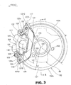
- FIG. 3 is a view as viewed in the direction of an arrow mark of FIG. 2 (an arrow mark (FRONT) in the figure represents the forward direction of the vehicle: this similarly applies to the succeeding figures).
- FIG. 3 shows that the brake caliper 111 is attached to the first arm 125 and the second arm 126 provided on the knuckle 88 (more particularly, a first caliper supporting portion 125a provided at an end portion of the first arm portion 125 and a second caliper supporting portion 126a provided at an end portion of the second arm portion 126) by means of bolts 117 and 118.
- the brake caliper 111 includes a caliper bracket 131 (a portion whose contour is indicated by a thick line) attached to the first arm 125 and the second arm 126, and a caliper assembly 134 connected to the caliper bracket 131 through a first connecting portion 132 and a second connecting portion 133.
- reference character 131A denotes a first attachment portion provided on the caliper bracket 131 for attaching the caliper bracket 131 to the first caliper supporting portion 125a of the first arm 125.
- reference character 131B denotes a second attachment portion provided on the caliper bracket 131 for attaching the caliper bracket 131 to the second caliper supporting portion 126a of the second arm 126.
- the caliper assembly 134 includes a caliper body 136 connected to the caliper bracket 131, a pair of pads 138 and 141 (only reference numeral 138 on this side is shown) disposed on the inner side of the caliper body 136 for sandwiching the brake disk 137 from the opposite sides, and a piston 142 accommodated for movement in the caliper body 136 for pressing the pads 138 and 141.
- the center of the front wheel 17 (refer to FIG. 1) is represented by a point 190, the center of the piston 142 by a point 191, the axial line of the bolt 117 by a point 192, the axial line of the bolt 118 by point 193, the distance from the point 190 to the point 191 by L1, and the distance from the point 190 to a point 192 (or another point 193) by L2, the distance L2 is greater than the distance L1 (L2 > L1).
- the bolts 117 and 118 for attaching the brake caliper 111 to the knuckle 88 are disposed on the outer side in a radial direction with respect to the center of the piston 142. Consequently, when brake torque upon braking acts upon the pads 138 and 141 (more particularly, the positions of the pads 138 and 141 corresponding to the position of the center of the piston 142), the load generated upon the bolts 117 and 118 can be reduced.
- FIG. 4 is a sectional view taken along line 4-4 of FIG. 3 and shows that a hub 146 is rotatably attached to the knuckle 88 through a bearing 145, and a axle 147 provided integrally on the equal speed joint 98 (refer to FIG. 2) is spline-coupled and attached to the inner side of the hub 146 by means of a nut 148. Further, the brake disk 137 is attached to the hub 146 by means of a plurality of bolts 151, and a cover member 152 is attached to the knuckle 88 by means of a plurality of bolts 153 in order to cover the brake disk 137 from the inward direction.
- reference character 154 denotes a wheel disc attached to the hub 146 by means of a plurality of bolts 155 and a plurality of nuts 156, 154a a rim of the wheel disc 154, 157 a snap ring, and reference numerals 158 and 159 denote dust seals.
- the cover member 152 includes a disk portion 152a extending radially outwardly and a flange portion 152b provided at part of an outer circumferential edge of the disk portion 152a.
- the cover member 152 is a member whose flange portion 152b is provided at a portion other than the circumferential edge of the lower portion of the 152a, that is, an outer circumferential edge of an upper portion and an outer circumferential edge of a rear portion of the disk portion 152a (more specifically, within a range of an angle ⁇ ).
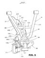
- FIG. 5 is a plan view showing the inboard side guard member and the outboard side guard member according to the present invention in an attached state.
- the front lower arm 41 is formed from a front arm 211, a rear arm 212 disposed rearwardly of the front arm 211, and a cross member 213 extending between the front arm 211 and the rear arm 212.
- a bracket 214 extends between and is attached to the front arm 211 and the cross member 213, and the inboard side guard member 102 (part of which is indicated by a thick line) is attached to the bracket 214 by means of a bolt 216 and a nut 217.
- the outboard side guard member 105 (part of which is indicated by a thick line) is attached to the knuckle 88 by means of bolts 218 and 218 (only one reference numeral 218 is shown).
- the inboard side guard member 102 includes a base portion 102a, which covers the front arm 211 from below, and an upright portion 102b formed integrally with the base portion 102a in such a manner as to extend upwardly from a front edge of the base portion 102a. Therefore, the inboard side guard member 102 can protect the rear arm 212 and the cross member 213 in addition to the front arm 211 from a flying stone or a colliding article from forwardly of the vehicle.
- Reference character 102c in FIG. 5 denotes an outer edge portion of the inboard side guard member 102 on the sideward side of the vehicle.
- the outer edge portion 102c is a portion provided at a position outside a range of movement of a second guard portion 105e provided on the free end side of the outboard side guard member 105.
- outboard side guard member 105 can protect not only the equal speed joint 98 and the rubber boot 96 of the drive shaft 93 from a flying stone or a colliding article from forwardly of the vehicle but also the brake caliper 111 from mud water and so forth from rearwardly of the vehicle.
- FIG. 6 is a perspective view of the outboard side guard member according to the present invention in an attached state.
- the outboard side guard member 105 is a member to integrally form attachment portions 105a, 105b to be attached to the knuckle 88, first guard portions 105c, 105d extending substantially in parallel to each other from the attachment portions 105a, 105b, and a second guard portion 105e connecting ends of the first guard portions 105c, 105d to each other.
- reference character 105f denotes an auxiliary guard portion provided integrally to a connection portion between the first guard portion 105c and the second guard portion 105e
- 105g an auxiliary guard portion provided integrally to a connection portion between the first guard portion 105d and the second guard portion 105e.
- FIG. 7 is a sectional view taken along line 7-7 of FIG. 6.
- the second guard portion 105e of the outboard side guard member 105 includes a base portion 105j extending substantially in a forward and backward direction of the vehicle, and an inclined portion 105k extending rearwardly obliquely inwardly (inward location is the center side of the vehicle, and the leftward in the figure) from a front end portion of the base portion 105j.
- the inclined portion 105k of the outboard side guard member 105 is extended inwardly obliquely rearwardly so as to coincide substantially with the direction in which a tangential line to an arc 219 drawn around the center provided by the king pin axis 115 (refer to FIG. 2), which is the center of rotation of the knuckle 88, extends.
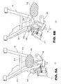
- FIGS. 8(a) and 8(b) are views illustrating operation of the outboard side guard member according to the present invention. It is to be noted that the outboard side guard member 105 is partly indicated by a thick line.
- snow is sometimes piled up on the front lower arm 41 to form a mass 202 (or a clod of mud or the like) and freezes on the front lower arm 41.
- the outboard side guard member 105 moves together with the knuckle 88 to a position at which it overlaps with the front arm 211 of the front lower arm 41 and pushes the mass 202 away from a position indicated by an imaginary line (position shown in FIG. 8(a)) as indicated by an arrow mark B.
- the outboard side guard member 105 serves as a scraper and breaks or scrapes off the mass 202 in FIG. 8(b).
- FIG. 9 is a perspective view showing a protector for a vehicle according to the present invention (the forward direction of the vehicle is indicated by an arrow mark (FRONT): this similarly applies to the succeeding figures).
- FIG. 9 shows that the outboard side guard member 105 as the front wheel side protector and a caliper bracket 111 are attached to the first arm 125 and the second arm 126 of the knuckle 88, and a brake caliper 108 is attached to the caliper bracket 111.
- reference numerals 1109 and 1109 denote bolts for attaching the caliper bracket 107 to the knuckle 88
- 1110 and 1110 denote bolts for attaching the brake caliper 108 to the caliper bracket 107.
- the outboard side guard member 105 is a member for covering the rubber boot 96 from forwardly and has a cutaway portion 1117 provided thereon for preventing interference of the outboard side guard member 105 with the brake caliper 111.
- FIG. 10 is a front elevational view showing an outboard side guard member attachment structure according to the present invention.
- Female threads 1111 and 1111 are formed on the first arm 125 and the second arm 126 of the knuckle 88, and bolt fitting holes 114 and 114 are formed in flange portions 1112 and 1113 formed on the outer side guard member 105.
- the bolts 104 and 104 are fitted into the bolt fitting holes 114 and 114 and screwed into the female threads 111 and 111 to attach the outboard side guard member 105 to the knuckle 88.
- the outboard side guard member 105 includes a boot covering portion 1115 for covering the rubber boot 96 (refer to FIG. 2), the cutaway portion 1117 cut away in a substantially channel shape, and the aforementioned flange portions 1112 and 1113 formed integrally on the boot covering portion 1115.
- reference numeral 121 denotes an upper arm connecting portion provided on the knuckle 88 for connecting the knuckle 88 to the upper arm and a lower arm connecting portion provided on the knuckle 88 for connecting the knuckle 88 to the lower arm.
- FIG. 11 is a plan view of the lower arm according to the present invention.
- the lower arm 1184 includes a substantially straight front pipe 1131, and a bracket 1132 attached to an end of the front pipe 1131 for connecting the lower arm 1184 to the knuckle 88 (refer to FIG. 2).
- the lower arm 84 further includes a rear pipe 1133 connected in a bent form to a rear portion of the bracket 1132, and a cross pipe 1134 extending between the front pipe 1131 and the rear pipe 1133.
- a bracket 1136 is attached such that it spans the front pipe 1131 and the cross pipe 1134, and a nut 1137 is attached to the bracket 1136.
- a bolt is screwed into the nut 1137 to attach the inboard side guard member 102 (refer to FIG.
- reference numerals 1138 and 1138 denote arm side attachment portions for attaching the lower arm 1184 to the arm supporting portions 82 (refer to FIG. 2)
- reference numeral 1141 denotes a reinforcement plate for reinforcing the connecting portion between the bracket 1132 and the rear pipe 1133.
- the inboard side guard member 102 since the inboard side guard member 102 is disposed such that it extends along the front side of the front pipe 1131 from below, the inboard side guard member 102 can be prevented from turning by the front pipe 1131 and can be secured to the lower arm 1184 only by means of the bolts and nuts 1137 in pair. Consequently, reduction of the cost by reduction of the number of parts can be achieved.
- FIGS. 12(a) and 12(b) are views illustrating operation of the outboard side guard member according to one embodiment of the present invention.
- the handle bar is operated for turning to the right and the knuckle 88 is swung in a direction indicated by an arrow mark around a support shaft 1145 (here, the support shaft 1145 is represented by a dot) provided on the upper arm connecting portion 1121 and the lower arm connecting portion 1122, then the outboard side guard member 105 moves toward the rubber boot 96 while it covers the front side of the rubber boot 96.
- a support shaft 1145 here, the support shaft 1145 is represented by a dot
- the handle bar is operated for turning to the left and the knuckle 88 is swung in a direction indicated by an arrow mark around the support shaft 1145, then the outer side guard member 105 moves away from the rubber boot 96 while it covers the front side of the rubber boot 96.
- the distance by which the outboard side guard member 105 moves away from the rubber boot 96 is smaller than that where a guard member is attached to a suspension arm as in the conventional art.
- FIG. 13 is a perspective view showing another embodiment of the protector for a vehicle according to the present invention.
- like elements to those in the embodiment of FIG. 9 are denoted by like reference characters, and detailed description of them is omitted herein.
- a knuckle 161 for supporting the front wheel for rotation thereon through a hub integrally includes an outboard side guard portion 1162.
- the outer side guard portion 1162 is attached to the first and second arms 1125 and 1126 as a front wheel side protector.
- the caliper bracket 1107 is attached to the first arm 1125 and the second arm 1126, and the brake caliper 108 is attached to the caliper bracket 111.
- the rubber boot 96 is covered from forwardly with the outboard side guard portion 1162.
- outboard side guard portion 1162 for protecting the rubber boot 96 is formed integrally on the knuckle 1161 in this manner, the number of parts can be reduced and the cost can be reduced.
- the rubber boot 95 is covered from forwardly with the inboard side guard member 102 and the rubber boot 96 is covered from forwardly with the outer side guard member 105
- the configuration is not limited to this.
- the forward obliquely downward portion of the rubber boot 95 and the lower portion of the rubber boot 95 may be covered with the inner side guard member 102
- the forward obliquely downward portion of the rubber boot 96 and the lower portion of the rubber boot 96 may be covered with the outer side guard member 105.
- the rubber boot 95 and the shaft 153 are covered from forwardly with the inner side guard member 151 as shown in FIG. 9, the configuration is not limited to this, and also the forward obliquely downward portion of the rubber boot 95 and the shaft and the lower portion of the rubber boot 95 and the shaft may be covered with the inner side guard member.
- a disk brake apparatus 110 including a brake disk 137 and a brake caliper 111 for sandwiching the brake disk 137 to brake the brake disk 137 is disposed on the inner side of a wheel disc 154 of each of left and right front wheels 17 and 17.
- An independent suspension system wherein each of the left and right front wheels 17 and 17 is supported by a front upper arm 40 as an upper arm and a front lower arm 41 as a lower arm is adopted.
- An inboard side guard member 102 is attached to the front lower arm 41 in order to protect a drive shaft 93, which transmits driving force to the front wheels 17, on the center side of a vehicle body from forwardly while an outboard side guard member 105 is attached to a knuckle 88 in order to protect the drive shaft 93 on the front wheel 17 side from forwardly.
- the outboard side guard member 105 is formed such that a second guard portion 105e as an end portion thereof, more particularly an inclined portion 105k, extends inwardly obliquely rearwardly of the vehicle body.
- the outboard side guard member 105 is formed such that the second guard portion 105e thereof extends inwardly obliquely rearwardly of the vehicle body. Therefore, when the vehicle is steered to move the outboard side guard member 105 together with the knuckle 88, the second guard portion 105e serves as a scraper and can easily scrape off, break, or push away mud, snow, or the like piled up on the front lower arm 41. Accordingly, cumbersome removal of mud, snow, and so forth by manual operation as in the conventional art can be eliminated.
- the inboard side guard member 102 covers a front portion and a front lower portion of the front lower arm 41 and includes an upright portion 192b disposed in the proximity of a range of movement of the second guard portion 105e of the outboard side guard member 105.
- the upright portion 102b Since the upright portion 102b is provided on the inboard side guard member 102, the upright portion 102b can protect a front portion and a front lower portion of the front lower arm 41. Further, the upright portion 102b is disposed in the proximity of the range of movement of the second guard portion 105e of the outboard side guard member 105. Thus, the inboard side guard member 102 and the outboard side member 105 can protect the substantially overall area of the drive shaft 93 within the range from the center side of the vehicle body to the knuckle 88. Accordingly, the driving ability of the irregular ground traveling vehicle 10 of the saddle type can be enhanced.
- the front lower arm 41 includes a front arm 211 provided on the front side of the vehicle and a rear arm 212 provided rearwardly of the front arm 211, and the second guard portion 105e of the outboard side guard member 105 overlaps with the front arm 211 as viewed in plan when the front wheels 17 are steered in the maximum.
- the second guard portion 105e of the outboard side guard member 105 is formed such that it overlaps with the front arm 211 as viewed in plan when the front wheel 17 is steered in the maximum, the second guard portion 105e of the outboard side guard member 105 can certainly scrape off, break, or pushed away mud, snow, or the like piled up on the front lower arm 41.
- the outboard side guard member 105 is a member wherein a first guard portion 105c, 105d as a caliper guard portion for covering the brake caliper 111 from the inner side and the second guard portion 105e provided at an end portion of the first guard portion 105c, 105d are formed integrally with each other.
- first guard portions 105c, 105d and the second guard portion 105e are formed integrally with each other, the number of parts can be reduced and the cost of the outboard side guard member 105 can be suppressed.
- the inclined portion 105k of the outboard side guard member 105 in the present embodiment is formed such that the cross section thereof extends substantially linearly as shown in FIG. 7, the shape of the cross section is not limited to this, but it may otherwise extend arcuately along the arc 219 shown in FIG. 5.
- the end portion of the outboard side guard member 105 is formed such that it extends inwardly obliquely rearwardly of the vehicle body, the direction of the end portion of the outboard side guard member 105 is not limited to this, but it may otherwise be formed so as to extend rearwardly of the vehicle body or inwardly of the vehicle body.
Landscapes
- Engineering & Computer Science (AREA)
- Mechanical Engineering (AREA)
- Vehicle Body Suspensions (AREA)
- Automatic Cycles, And Cycles In General (AREA)
Applications Claiming Priority (4)
| Application Number | Priority Date | Filing Date | Title |
|---|---|---|---|
| JP2004024689A JP4627404B2 (ja) | 2004-01-30 | 2004-01-30 | 鞍乗り型不整地走行車両用保護具 |
| JP2004024689 | 2004-01-30 | ||
| JP2004257315A JP4343802B2 (ja) | 2004-09-03 | 2004-09-03 | 鞍乗り型不整地走行車両のガード部材 |
| JP2004257315 | 2004-09-03 |
Publications (3)
| Publication Number | Publication Date |
|---|---|
| EP1559594A2 true EP1559594A2 (de) | 2005-08-03 |
| EP1559594A3 EP1559594A3 (de) | 2006-05-10 |
| EP1559594B1 EP1559594B1 (de) | 2010-08-25 |
Family
ID=34656297
Family Applications (1)
| Application Number | Title | Priority Date | Filing Date |
|---|---|---|---|
| EP05100486A Expired - Lifetime EP1559594B1 (de) | 2004-01-30 | 2005-01-26 | Antriebswellenschutzvorrichtung fur ein Geländefahrzeug mit Sattel |
Country Status (6)
| Country | Link |
|---|---|
| US (1) | US7377549B2 (de) |
| EP (1) | EP1559594B1 (de) |
| CN (1) | CN100417536C (de) |
| CA (1) | CA2495399C (de) |
| DE (1) | DE602005023083D1 (de) |
| PT (1) | PT1559594E (de) |
Cited By (7)
| Publication number | Priority date | Publication date | Assignee | Title |
|---|---|---|---|---|
| FR2898327A1 (fr) * | 2006-03-09 | 2007-09-14 | Axp Racing Sarl | Sabot de protection pour quadricycle ou similaire equipe d'un tel sabot. |
| FR3024423A1 (fr) * | 2014-08-01 | 2016-02-05 | Peugeot Citroen Automobiles Sa | Dispositif aerodynamique pour un train de vehicule |
| FR3038673A1 (fr) * | 2015-12-30 | 2017-01-13 | Chassis Brakes Int Bv | Dispositif de frein a tambour comportant un element motoreducteur de motorisation d'actionneur et vehicule automobile associe |
| EP3135571A1 (de) * | 2015-08-31 | 2017-03-01 | Honda Motor Co., Ltd. | Grätschsitzfahrzeug |
| FR3052719A1 (fr) * | 2016-06-21 | 2017-12-22 | Renault Sas | "train roulant de vehicule automobile equipe d'un bouclier de protection d'un joint homocinetique" |
| US10591003B2 (en) | 2017-06-16 | 2020-03-17 | Polaris Industries Inc. | Brake assembly shield and scraper |
| EP3967529A1 (de) * | 2020-09-15 | 2022-03-16 | Segway Technology Co., Ltd. | Radaufhängung für gelandefahrzeug |
Families Citing this family (24)
| Publication number | Priority date | Publication date | Assignee | Title |
|---|---|---|---|---|
| CA2502131C (en) * | 2004-03-30 | 2011-12-20 | Honda Motor Co., Ltd. | Independent vehicle suspension with stabilizer |
| US7549494B1 (en) * | 2005-04-02 | 2009-06-23 | Zichek Daniel A | Transverse mounted mid-engine three wheel vehicle |
| US7571918B2 (en) * | 2006-03-31 | 2009-08-11 | Honda Motor Company, Ltd. | Suspension arm for a vehicle |
| JP4881780B2 (ja) * | 2007-03-30 | 2012-02-22 | 本田技研工業株式会社 | 車両のスクレイパ構造 |
| US20080265661A1 (en) * | 2007-04-30 | 2008-10-30 | Yamaha Motor Manufacturing Corporation Of America | Driveshaft boot protector |
| JP5049235B2 (ja) * | 2008-09-09 | 2012-10-17 | 本田技研工業株式会社 | 車両のサスペンションアーム |
| US8028781B2 (en) * | 2009-04-21 | 2011-10-04 | Deere & Company | Flexible under-frame shield |
| US8402878B2 (en) * | 2009-10-01 | 2013-03-26 | Oshkosh Corporation | Axle assembly |
| US9045014B1 (en) | 2012-03-26 | 2015-06-02 | Oshkosh Defense, Llc | Military vehicle |
| USD966958S1 (en) | 2011-09-27 | 2022-10-18 | Oshkosh Corporation | Grille element |
| CN103434356B (zh) * | 2013-09-03 | 2016-06-08 | 苏州巴吉赛车科技有限公司 | 一种钢板式前上悬臂 |
| JP6301141B2 (ja) * | 2014-01-30 | 2018-03-28 | 本田技研工業株式会社 | 不整地走行車両の懸架構造 |
| JP6096822B2 (ja) * | 2015-03-26 | 2017-03-15 | 富士重工業株式会社 | 整流装置 |
| AU2017248349B2 (en) | 2016-04-08 | 2021-11-11 | Oshkosh Corporation | Leveling system for lift device |
| US10137873B2 (en) * | 2017-03-14 | 2018-11-27 | Honda Motor Co., Ltd. | Side-by-side all-terrain vehicle |
| US10808792B2 (en) * | 2018-07-18 | 2020-10-20 | Honda Motor Co, Ltd. | Apparatus for shielding vehicle component |
| CN108688759B (zh) * | 2018-07-20 | 2024-06-04 | 重庆隆鑫机车有限公司 | 减震器保护板、减震器保护结构及车辆 |
| CA3299413A1 (en) | 2019-04-30 | 2026-03-02 | Polaris Industries Inc. | Vehicle with removable final drive |
| US12415394B2 (en) | 2019-04-30 | 2025-09-16 | Polaris Industries, Inc. | Vehicle |
| US11142030B2 (en) * | 2019-12-24 | 2021-10-12 | Kawasaki Jukogyo Kabushiki Kaisha | Protection structure for vehicle suspension device |
| US12187127B2 (en) | 2020-05-15 | 2025-01-07 | Polaris Industries Inc. | Off-road vehicle |
| CN112848825A (zh) * | 2021-02-21 | 2021-05-28 | 石河子大学 | 一种全地形车三连杆后悬架 |
| US11376910B1 (en) * | 2021-03-12 | 2022-07-05 | Kawasaki Motors, Ltd. | Suspension structure of utility vehicle |
| MX2023006716A (es) | 2022-06-13 | 2023-12-14 | Polaris Inc | Tren de potencia para vehiculo utilitario. |
Citations (1)
| Publication number | Priority date | Publication date | Assignee | Title |
|---|---|---|---|---|
| JPH0637090U (ja) | 1992-10-28 | 1994-05-17 | 本田技研工業株式会社 | 車輪の懸架装置 |
Family Cites Families (14)
| Publication number | Priority date | Publication date | Assignee | Title |
|---|---|---|---|---|
| US4308931A (en) * | 1980-01-22 | 1982-01-05 | International Harvester Company | Guard for drive shaft in an articulated tractor |
| US4655307A (en) * | 1985-05-06 | 1987-04-07 | Robert Lamoureux | Belly pan for four wheel all terrain vehicles |
| JPH0637090A (ja) | 1992-07-20 | 1994-02-10 | Fuji Film Micro Device Kk | 半導体装置の製造方法 |
| US5797607A (en) * | 1995-08-30 | 1998-08-25 | Kopczynski; John F. | Vehicle with vertically movable and vertically pulsating wheels |
| US5794976A (en) * | 1995-12-29 | 1998-08-18 | Stevicks; Roy A. | Safety shield for all terrain vehicles |
| US5915728A (en) * | 1997-07-14 | 1999-06-29 | Blackburn; Clyde | Guard for vehicles |
| US6182784B1 (en) * | 1997-10-22 | 2001-02-06 | Keith Edward Pestotnik | All-terrain vehicle, drive train for such a vehicle and method of its operation |
| DE19839469C1 (de) * | 1998-08-29 | 2000-05-25 | Walterscheid Gmbh Gkn | Lagerring zur Lagerung einer Schutzvorrichtung |
| JP2000233655A (ja) * | 1999-02-15 | 2000-08-29 | Yamaha Motor Co Ltd | 鞍乗型車両における走行用駆動装置 |
| US6857499B2 (en) * | 2000-11-14 | 2005-02-22 | Kawasaki Jukogyo Kabushiki Kaisha | Transmission and gear position detector for all-terrain vehicle |
| US6579187B2 (en) * | 2001-04-30 | 2003-06-17 | Gkn Automotive, Inc. | Shield for use in a constant velocity joint |
| JP4010127B2 (ja) * | 2001-09-14 | 2007-11-21 | スズキ株式会社 | 変速機構の冷却構造 |
| US6692366B1 (en) * | 2002-09-14 | 2004-02-17 | Kevin Savant | CV joint protector for ATV |
| US7055895B1 (en) * | 2004-06-04 | 2006-06-06 | John King | Protective plate assembly for land vehicle drive line and wheel differential |
-
2005
- 2005-01-26 EP EP05100486A patent/EP1559594B1/de not_active Expired - Lifetime
- 2005-01-26 DE DE602005023083T patent/DE602005023083D1/de not_active Expired - Lifetime
- 2005-01-26 PT PT05100486T patent/PT1559594E/pt unknown
- 2005-01-27 US US11/050,831 patent/US7377549B2/en not_active Expired - Lifetime
- 2005-01-28 CN CNB2005100061307A patent/CN100417536C/zh not_active Expired - Fee Related
- 2005-01-28 CA CA002495399A patent/CA2495399C/en not_active Expired - Fee Related
Patent Citations (1)
| Publication number | Priority date | Publication date | Assignee | Title |
|---|---|---|---|---|
| JPH0637090U (ja) | 1992-10-28 | 1994-05-17 | 本田技研工業株式会社 | 車輪の懸架装置 |
Cited By (8)
| Publication number | Priority date | Publication date | Assignee | Title |
|---|---|---|---|---|
| FR2898327A1 (fr) * | 2006-03-09 | 2007-09-14 | Axp Racing Sarl | Sabot de protection pour quadricycle ou similaire equipe d'un tel sabot. |
| FR3024423A1 (fr) * | 2014-08-01 | 2016-02-05 | Peugeot Citroen Automobiles Sa | Dispositif aerodynamique pour un train de vehicule |
| EP3135571A1 (de) * | 2015-08-31 | 2017-03-01 | Honda Motor Co., Ltd. | Grätschsitzfahrzeug |
| FR3038673A1 (fr) * | 2015-12-30 | 2017-01-13 | Chassis Brakes Int Bv | Dispositif de frein a tambour comportant un element motoreducteur de motorisation d'actionneur et vehicule automobile associe |
| FR3052719A1 (fr) * | 2016-06-21 | 2017-12-22 | Renault Sas | "train roulant de vehicule automobile equipe d'un bouclier de protection d'un joint homocinetique" |
| US10591003B2 (en) | 2017-06-16 | 2020-03-17 | Polaris Industries Inc. | Brake assembly shield and scraper |
| US11193548B2 (en) | 2017-06-16 | 2021-12-07 | Polaris Industries Inc. | Brake assembly shield and scraper |
| EP3967529A1 (de) * | 2020-09-15 | 2022-03-16 | Segway Technology Co., Ltd. | Radaufhängung für gelandefahrzeug |
Also Published As
| Publication number | Publication date |
|---|---|
| US7377549B2 (en) | 2008-05-27 |
| CA2495399A1 (en) | 2005-07-30 |
| DE602005023083D1 (de) | 2010-10-07 |
| CN100417536C (zh) | 2008-09-10 |
| PT1559594E (pt) | 2010-11-02 |
| CN1654239A (zh) | 2005-08-17 |
| EP1559594A3 (de) | 2006-05-10 |
| CA2495399C (en) | 2008-04-15 |
| EP1559594B1 (de) | 2010-08-25 |
| US20050167179A1 (en) | 2005-08-04 |
Similar Documents
| Publication | Publication Date | Title |
|---|---|---|
| EP1559594B1 (de) | Antriebswellenschutzvorrichtung fur ein Geländefahrzeug mit Sattel | |
| US7744104B2 (en) | Suspension arm and cushion arm structure for vehicle | |
| CN102126409B (zh) | 车辆 | |
| JP4052569B2 (ja) | サスペンションアームの取付構造 | |
| JP2009264484A (ja) | ディスクブレーキカバー構造 | |
| US7451857B2 (en) | Seat mount structure for saddle ride type vehicle | |
| US20090051140A1 (en) | Fork Protector and Straddle-Type Vehicle Equipped with Fork Protector | |
| JP4627404B2 (ja) | 鞍乗り型不整地走行車両用保護具 | |
| US7708107B2 (en) | Suspension structure for a vehicle | |
| US4650023A (en) | Rear wheel steering device for motorcycles | |
| JP4343802B2 (ja) | 鞍乗り型不整地走行車両のガード部材 | |
| US4722415A (en) | Saddle riding type vehicle for running on rough lands | |
| JP4057259B2 (ja) | 車両の車速センサ取付構造 | |
| US6568497B1 (en) | Protective structure for axle joints | |
| JP5111874B2 (ja) | クッション支持構造 | |
| JP2006069437A (ja) | 鞍乗り型不整地走行車両のブレーキホース支持構造 | |
| JP5049022B2 (ja) | サスペンションアーム構造 | |
| JP2941219B2 (ja) | 鞍乗型四輪不整地走行車の車体前部構造 | |
| JP2001099200A (ja) | 不整地走行用車輪のドラムブレーキ構造 | |
| JP5235055B2 (ja) | 駆動輪懸架構造 | |
| JPS62149589A (ja) | 荒地走行用鞍乗型車両の前輪用油圧式ディスクブレーキ装置 | |
| JP4558555B2 (ja) | 鞍乗型車両のクッション取付構造 | |
| JPS6326308Y2 (de) | ||
| JP4459851B2 (ja) | 鞍乗型車両のフレーム構造 | |
| JPH11263134A (ja) | 鞍乗型不整地走行車両の動力伝達装置保護構造 |
Legal Events
| Date | Code | Title | Description |
|---|---|---|---|
| PUAI | Public reference made under article 153(3) epc to a published international application that has entered the european phase |
Free format text: ORIGINAL CODE: 0009012 |
|
| AK | Designated contracting states |
Kind code of ref document: A2 Designated state(s): AT BE BG CH CY CZ DE DK EE ES FI FR GB GR HU IE IS IT LI LT LU MC NL PL PT RO SE SI SK TR |
|
| AX | Request for extension of the european patent |
Extension state: AL BA HR LV MK YU |
|
| PUAL | Search report despatched |
Free format text: ORIGINAL CODE: 0009013 |
|
| AK | Designated contracting states |
Kind code of ref document: A3 Designated state(s): AT BE BG CH CY CZ DE DK EE ES FI FR GB GR HU IE IS IT LI LT LU MC NL PL PT RO SE SI SK TR |
|
| AX | Request for extension of the european patent |
Extension state: AL BA HR LV MK YU |
|
| 17P | Request for examination filed |
Effective date: 20061106 |
|
| AKX | Designation fees paid |
Designated state(s): DE ES FR GB PT |
|
| 17Q | First examination report despatched |
Effective date: 20070205 |
|
| GRAP | Despatch of communication of intention to grant a patent |
Free format text: ORIGINAL CODE: EPIDOSNIGR1 |
|
| GRAS | Grant fee paid |
Free format text: ORIGINAL CODE: EPIDOSNIGR3 |
|
| GRAA | (expected) grant |
Free format text: ORIGINAL CODE: 0009210 |
|
| AK | Designated contracting states |
Kind code of ref document: B1 Designated state(s): DE ES FR GB PT |
|
| REG | Reference to a national code |
Ref country code: GB Ref legal event code: FG4D |
|
| REF | Corresponds to: |
Ref document number: 602005023083 Country of ref document: DE Date of ref document: 20101007 Kind code of ref document: P |
|
| REG | Reference to a national code |
Ref country code: PT Ref legal event code: SC4A Free format text: AVAILABILITY OF NATIONAL TRANSLATION Effective date: 20101025 |
|
| REG | Reference to a national code |
Ref country code: ES Ref legal event code: FG2A Effective date: 20110128 |
|
| PLBE | No opposition filed within time limit |
Free format text: ORIGINAL CODE: 0009261 |
|
| STAA | Information on the status of an ep patent application or granted ep patent |
Free format text: STATUS: NO OPPOSITION FILED WITHIN TIME LIMIT |
|
| 26N | No opposition filed |
Effective date: 20110526 |
|
| REG | Reference to a national code |
Ref country code: DE Ref legal event code: R097 Ref document number: 602005023083 Country of ref document: DE Effective date: 20110526 |
|
| PGFP | Annual fee paid to national office [announced via postgrant information from national office to epo] |
Ref country code: PT Payment date: 20120126 Year of fee payment: 8 |
|
| PGFP | Annual fee paid to national office [announced via postgrant information from national office to epo] |
Ref country code: GB Payment date: 20120125 Year of fee payment: 8 |
|
| PGFP | Annual fee paid to national office [announced via postgrant information from national office to epo] |
Ref country code: FR Payment date: 20130204 Year of fee payment: 9 Ref country code: DE Payment date: 20130123 Year of fee payment: 9 |
|
| REG | Reference to a national code |
Ref country code: PT Ref legal event code: MM4A Free format text: LAPSE DUE TO NON-PAYMENT OF FEES Effective date: 20130726 |
|
| GBPC | Gb: european patent ceased through non-payment of renewal fee |
Effective date: 20130126 |
|
| PG25 | Lapsed in a contracting state [announced via postgrant information from national office to epo] |
Ref country code: PT Free format text: LAPSE BECAUSE OF NON-PAYMENT OF DUE FEES Effective date: 20130726 |
|
| PG25 | Lapsed in a contracting state [announced via postgrant information from national office to epo] |
Ref country code: GB Free format text: LAPSE BECAUSE OF NON-PAYMENT OF DUE FEES Effective date: 20130126 |
|
| PGFP | Annual fee paid to national office [announced via postgrant information from national office to epo] |
Ref country code: ES Payment date: 20131211 Year of fee payment: 10 |
|
| REG | Reference to a national code |
Ref country code: DE Ref legal event code: R119 Ref document number: 602005023083 Country of ref document: DE |
|
| PG25 | Lapsed in a contracting state [announced via postgrant information from national office to epo] |
Ref country code: DE Free format text: LAPSE BECAUSE OF NON-PAYMENT OF DUE FEES Effective date: 20140801 |
|
| REG | Reference to a national code |
Ref country code: FR Ref legal event code: ST Effective date: 20140930 |
|
| REG | Reference to a national code |
Ref country code: DE Ref legal event code: R119 Ref document number: 602005023083 Country of ref document: DE Effective date: 20140801 |
|
| PG25 | Lapsed in a contracting state [announced via postgrant information from national office to epo] |
Ref country code: FR Free format text: LAPSE BECAUSE OF NON-PAYMENT OF DUE FEES Effective date: 20140131 |
|
| REG | Reference to a national code |
Ref country code: ES Ref legal event code: FD2A Effective date: 20160226 |
|
| PG25 | Lapsed in a contracting state [announced via postgrant information from national office to epo] |
Ref country code: ES Free format text: LAPSE BECAUSE OF NON-PAYMENT OF DUE FEES Effective date: 20150127 |