EP1555761B1 - Apparatus and method for estimating interference and noise in a communication system - Google Patents
Apparatus and method for estimating interference and noise in a communication system Download PDFInfo
- Publication number
- EP1555761B1 EP1555761B1 EP04030907A EP04030907A EP1555761B1 EP 1555761 B1 EP1555761 B1 EP 1555761B1 EP 04030907 A EP04030907 A EP 04030907A EP 04030907 A EP04030907 A EP 04030907A EP 1555761 B1 EP1555761 B1 EP 1555761B1
- Authority
- EP
- European Patent Office
- Prior art keywords
- sub
- carriers
- noise
- interference
- signal
- Prior art date
- Legal status (The legal status is an assumption and is not a legal conclusion. Google has not performed a legal analysis and makes no representation as to the accuracy of the status listed.)
- Not-in-force
Links
Images


Classifications
-
- H—ELECTRICITY
- H04—ELECTRIC COMMUNICATION TECHNIQUE
- H04L—TRANSMISSION OF DIGITAL INFORMATION, e.g. TELEGRAPHIC COMMUNICATION
- H04L1/00—Arrangements for detecting or preventing errors in the information received
- H04L1/20—Arrangements for detecting or preventing errors in the information received using signal quality detector
- H04L1/206—Arrangements for detecting or preventing errors in the information received using signal quality detector for modulated signals
-
- H—ELECTRICITY
- H04—ELECTRIC COMMUNICATION TECHNIQUE
- H04B—TRANSMISSION
- H04B1/00—Details of transmission systems, not covered by a single one of groups H04B3/00 - H04B13/00; Details of transmission systems not characterised by the medium used for transmission
- H04B1/06—Receivers
- H04B1/10—Means associated with receiver for limiting or suppressing noise or interference
- H04B1/1027—Means associated with receiver for limiting or suppressing noise or interference assessing signal quality or detecting noise/interference for the received signal
-
- H—ELECTRICITY
- H04—ELECTRIC COMMUNICATION TECHNIQUE
- H04B—TRANSMISSION
- H04B17/00—Monitoring; Testing
- H04B17/30—Monitoring; Testing of propagation channels
- H04B17/309—Measuring or estimating channel quality parameters
- H04B17/345—Interference values
-
- H—ELECTRICITY
- H04—ELECTRIC COMMUNICATION TECHNIQUE
- H04L—TRANSMISSION OF DIGITAL INFORMATION, e.g. TELEGRAPHIC COMMUNICATION
- H04L27/00—Modulated-carrier systems
- H04L27/26—Systems using multi-frequency codes
- H04L27/2601—Multicarrier modulation systems
- H04L27/2647—Arrangements specific to the receiver only
Definitions
- the present invention relates generally to an apparatus and method for estimating interference and noise and more particularly to an apparatus and method for estimating a carrier to interference and noise ratio (CINR) that can estimate the CINR as one measure of reception performance in a wireless communication system.
- CINR carrier to interference and noise ratio
- orthogonal frequency division multiplexing OFDM
- OFDMA orthogonal frequency division multiple access
- the OFDM is commonly applied to digital transmission technology such as digital/audio broadcasting, digital television (TV), a wireless local area network (WLAN), a wireless asynchronous transfer mode (WATM), a fixed or mobile broadband wireless access (BWA), etc.
- digital/audio broadcasting digital television
- WLAN wireless local area network
- WATM wireless asynchronous transfer mode
- BWA fixed or mobile broadband wireless access
- the OFDM was not widely used because of hardware complexity, but the OFDM has recently become implementable with the development of various digital signal processing technologies including fast Fourier transform (FFT) and inverse fast Fourier transform (IFFT).
- FFT fast Fourier transform
- IFFT inverse fast Fourier transform
- the OFDM is similar to conventional frequency division multiplexing (FDM) and can acquire optimum transmission efficiency during high-speed data transmission by transmitting sub-carriers while maintaining orthogonality there between.
- the OFDM has better frequency efficiency and is inherently robust against multi-path fading.
- the OFDM is robust against frequency selective fading using a superimposed frequency spectrum and reduces the effects of inter-symbol interference using a guard interval. Therefore, the OFDM enables simple design of a hardware equalizer and is robust against impulse noise.
- the OFDM system may be required to measure a carrier to interference and noise ratio (CINR) as a parameter necessary for power control or adaptive modulation/and coding.
- CINR carrier to interference and noise ratio
- U.S. Patent No. 6,456,653 discloses a method for estimating a noise level from unused sub-carriers.
- the OFDM system performs an IFFT operation for data to be transmitted from a transmitter and transmits a result of the IFFT operation.
- an IFFT size is based on N FFT points, N sub-carriers are used and N unused sub-carriers are filled with zeros.
- the mixed data and noise are output from the N used sub-carriers, and only noise is output from the N unused sub-carriers.
- a noise level is measured from the N unused sub-carriers. It is assumed that a value of the measured noise level is the same as a level of noise mixed with data.
- the noise level is subtracted from a power level received from the N used sub-carriers, such that a true-signal level is estimated. As a result, a ratio between the true-signal level and the noise level is obtained as a desired SNR estimation value.
- the conventional SNR estimation method suffers extreme degradation in estimation performance when the number of unused sub-carriers is very small as compared with the number of used sub-carriers. Further, the conventional SNR estimation method cannot estimate an interference signal, because the interference signal is not incoming into the unused sub-carriers from other users using the same band.
- Muneta S. et al.: "A New Frequency-Domain Link Adaptation Scheme for Broadband OFDM Systems" Vehicular Technology Conference, 1999. VTC 1999 - Fall. IEEE VTS 50th Amsterdam, Netherlands, September 19-22, 1999, Picataway, NJ, USA, IEEE, US, vol. 1, pages 253 - 257 relates to a new frequency-domain link adaptation scheme for broadband OFDM systems.
- System throughput of an OFDM system can be enhanced by using link adaptation; the best set of modulation scheme and FEC coding rate is dynamically selected to achieve the target PER before ARQ.
- An important practical issue in applying adaptation is how to estimate the link quality precisely. Link quality is well assessed by CNR and the delay spread. Two link quality estimation functions, one examines the correlation between sub-carriers while the other considers CNR, are introduced. Both are simple to implement in combination with frequency-domain initial equalizer.
- US 2003/223354 A1 relates to a signal to interference-plus-noise power ratio measurement for subchannel signals within an OFDM communication system.
- Fast- Fourier transform based SINR measurements can be computed on frame by frame or greater interval for individual or groupings of subchannel signals. Given a known transmitted time domain OFDM frame preamble, and the corresponding channel and interference-plus-noise corrupted received time domain frame preamble, the technique first computes the power spectral densities of the received signal of interest and of a received unwanted interference-plus-noise signal. The fast Fourier transform computed power spectral densities are then used to compute average received signal and received interference-plus-noise power measurements for specified individual or groupings of OFDM subchannel signals.
- the power measurements are then frame averaged using a recursive exponential smoothing technique.
- the frame-averaged signal and interference-plus-noise power measurements are then used to form quantized measurements of signal to interference-plus-noise power ratio for the specified OFDM subchannel signals of the received frame.
- EP 1 207 663 A relates to improvement in the detection of a reception quality signal used particularly in antenna adjustment.
- CINR carrier to interference and noise ratio
- an apparatus for estimating noise power in a communication system includes: a correlator for correlating a plurality of sub-carriers with a preset reference sequence on an element-by-element basis and outputting a result of the correlation; a noise calculator for calculating a difference between/among a correlation value associated with each of the plurality of sub-carriers and a correlation value produced from at least one adjacent sub-carrier; and a noise power calculator for calculating noise power from the difference between the correlation values calculated by the noise calculator.
- the above can be accomplished by a method for correlating a plurality of sub-carriers with a reference sequence on an element-by-element basis; calculating a difference between/among a correlation value associated with each of the plurality of sub-carriers and a correlation value produced from at least one adjacent sub-carrier; and calculating noise power from the difference between/among the correlation values associated with the sub-carriers.
- the embodiment of present invention estimates the interference and noise power using channel characteristics based on the similarity between received signal sub-carriers that are adjacent to each other in frequency. In a difference between adjacent sub-carriers of the embodiment of present invention, signal components are canceled out and therefore, only interference and noise components remain.
- the above difference may be estimated noise value if there is noise.
- the above difference may be estimated interference and noise value if there are interference and noise.
- FIG. 1 is a block diagram illustrating a conventional orthogonal frequency division multiplexing (OFDM) transmitter.
- the OFDM transmitter 100 includes a pilot/preamble inserter 121, an inverse fast Fourier transform (IFFT) processor 123, a parallel-to-serial (P/S) converter 125, a guard interval (GI) inserter 127, a radio frequency (RF) processor 131, and an antenna 133.
- the pilot/preamble inserter 121 generates a plurality of sub-channels and a pilot symbol and a preamble set in the OFDM communication system.
- the pilot/preamble inserter 121 inserts the generated pilot symbol into the plurality of sub-channels, that is, data symbols.
- the pilot sub-carrier is inserted into the sub-channels conveying the data symbols in order to perform channel estimation. Locations of pilot sub-carriers to be transmitted are pre-defined in the OFDM communication system. Moreover, the generated preamble is typically located at a frame header in the form of one OFDMA symbol.
- the pilot and preamble use different sequences according to a base station.
- the IFFT processor 123 performs an IFFT operation for a plurality of input sub-channels and then outputs a result of the IFFT operation to the P/S converter 125.
- the P/S converter 125 converts an input parallel signal into a serial signal and outputs the serial signal to the GI inserter 127.
- the GI inserter 127 inserts a GI for reducing the effects of inter-symbol interference (ISI), etc., between sub-channels output from the IFFT processor 123, and outputs a result of the insertion to the RF processor 131.
- the RF processor 131 transmits channel data received from the GI inserter 127 via an antenna 133.
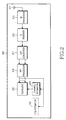
- FIG. 2 is a block diagram illustrating an OFDM receiver including a carrier to interference and noise ratio (CINR) estimator in accordance with the present invention.
- the OFDM receiver 200 includes an antenna 211, an RF processor 213, a guard interval (GI) remover 215, a serial-to-parallel (S/P) converter 217, an FFT processor 219, an equalizer 221, a channel estimator 223, and a channel quality information (CQI) estimator 225.
- GI guard interval
- S/P serial-to-parallel
- FFT processor 219 an equalizer 221, a channel estimator 223, and a channel quality information (CQI) estimator 225.
- CQI channel quality information
- the RF processor 213 outputs channel data from a radio channel received via the antenna 211 to the GI remover 215.
- the GI remover 215 removes a GI from the received channel data.
- the S/P converter 217 converts serial data from which the GI is removed and redundant data into a plurality of pieces of parallel data, and outputs the pieces of parallel data to the FFT processor 219.
- the FFT processor 219 performs an FFT operation for the pieces of parallel data and redundant data, and outputs a result of the FFT operation to the equalizer 221.
- the equalizer 221 removes channel signal distortion associated with the serial data and redundant data based on the result of the FFT operation, and outputs data from which the signal distortion is removed.
- the channel estimator 223 estimates a channel state, i.e., the distortion in phase and amplitude on a frequency domain due to channel degradation incurred at the transmission and reception time and compensates for the distortion .
- the CQI estimator 225 measures channel quality, that is, a carrier to interference and noise ratio (CINR).
- CINR carrier to interference and noise ratio
- the OFDM receiver receives the digital signal and measures a CINR from the digital signal received thereby. More specifically, the present invention uses a pilot signal after the FFT operation, such that the CINR can be measured.
- the pilot signal has a preset sequence and that binary phase shift keying (BPSK) modulation is used.
- BPSK binary phase shift keying
- the pilot sequence consists of 1's and 0's. It is assumed that a signal denoted by "1" is transmitted as a complex-number signal "1" and a signal denoted by "0” is transmitted as a complex-number signal "-1" without loss of generality.
- the reference signal is considered as a pilot signal in the preferred embodiment of the present invention, if there is a preamble located in a front part of a frame, a mid-amble located in the middle thereof, and a post-amble located in the end thereof, each of these items or the combination thereof can also be used.
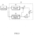
- FIG. 3 is a block diagram illustrating a configuration of the CINR estimator in accordance with the present invention.
- the CINR estimator 400 receives a pilot signal output from the FFT processor 219 and outputs the received signal to a signal power estimator 420 and an interference and noise power estimator 430.
- the signal power estimator 420 estimates power of the received signal. More specifically, the signal power estimator 420 produces power of each sub-carrier included in the signal received from the FFT processor 219. Subsequently, the signal power estimator 420 produces the total signal power by summing all sub-carrier power values, and then outputs the produced signal power to a subtracter 440.
- the interference and noise power estimator 430 estimates interference and noise power of the received signal.
- the embodiment of the present invention estimates the interference and noise power using channel characteristics based on the similarity between received signal sub-carriers that are adjacent to each other in frequency. That is, the present invention uses a difference between adjacent sub-carrier signals.
- the above-described method is referred to as a difference of adjacent sub-carrier signal (DASS)-based method in the embodiment of the present invention.
- DASS difference of adjacent sub-carrier signal
- the interference and noise power estimator 430 correlates a preset pilot sequence with a plurality of sub-carriers of the received signal on an element-by-element basis, and produces correlation values associated with the plurality of sub-carriers. Subsequently, the interference and noise estimator 430 calculates the difference between a correlation value of each sub-carrier and a correlation value produced from at least one adjacent sub-carrier.
- the number of adjacent sub-carriers having similar channel characteristics can be arbitrarily designated.
- an adjacent sub-carrier of each sub-carrier can be a sub-carrier closest to each sub-carrier. That is, the number of sub-carriers can be different according to characteristics of the communication system to which the present invention is applied. For example, in order for the system to be simply implemented, only one sub-carrier closest to each sub-carrier can be used. Alternatively, the number of adjacent sub-carriers can be differently used in relation to each sub-carrier.
- the interference and noise power estimator 430 produces interference and noise power from the interference and noise components, and outputs the produced interference and noise power to the subtracter 440.
- the subtracter 440 subtracts the interference and noise power produced by the interference and noise power estimator 430 from the signal power produced by the signal power estimator 420 and produces power of the pure received signal where the interference and noise components have been removed.
- a reciprocal-number generator 450 generates a reciprocal number of the interference and noise power value produced by the interference and noise power estimator 430, and provides the generated reciprocal number of the interference and noise power value to a multiplier 460.
- the multiplier 460 divides a value of (Total reception power - Total interference and noise power) by the total interference and noise power in order to produce a CINR estimation value. That is, the CINR estimation value is a ratio between the estimation value of true-signal power and the estimation value of interference and noise power.
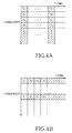
- the present invention includes three different pilot sequence location patterns to be used for estimating the CINR according to a sub-carrier signal in the received pilot signal. The three methods will be described herein below with reference to FIGS. 4A to 4C .
- FIGS. 4A to 4C are explanatory views illustrating CINR estimation methods in accordance with the present invention.
- a pilot and/or preamble signal consisting of N sub-carrier signals for the duration of one OFDM symbol is used.
- a plurality of sub-carriers are present in the same time domain for the OFDM symbol duration.
- the embodiment illustrated in FIG. 4A takes advantage of the fact that channel characteristics of the sub-carriers on the same time domain are similar to those of adjacent sub-carriers.
- the CINR estimator 400 uses a plurality of sub-carriers having the same time domain and different frequency domains among sub-carriers of the pilot and/or preamble signal output from the FFT processor 219.
- the pilot or preamble signal consisting of N sub-carrier signals for a plurality of OFDM symbol durations is used.
- a plurality of sub-carriers are present on the same frequency domain for the plurality of OFDM symbol durations.
- the channel characteristics of the sub-carriers on the same frequency domain are similar to those of adjacent sub-carriers.
- the CINR estimator 400 uses a plurality of sub-carriers having the same frequency domain and different time domains among sub-carriers of the pilot and/or preamble signal output by the FFT processor 219.
- a pilot or preamble signal consisting of N sub-carriers within a predetermined data domain including sub-carriers having different frequency domains and different time domains from the received pilot signal is used. That is, a plurality of sub-carriers are randomly selected to be used for estimating the CINR from the predetermined data domain. In this case, a correlation coefficient between each sub-carrier and its adjacent sub-carrier is made to be as close to "1" as possible by selecting the order of the pilot the sub-carriers appropriately. In FIG. 4C , the channel characteristics of sub-carriers close to each other are similar to those of their adjacent sub-carriers. Therefore, the CINR estimator 400 uses the sub-carriers randomly selected from the predetermined data domain consisting of the sub-carriers of the pilot and/or preamble signal output from the FFT processor 219.
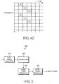
- FIG. 5 is a block diagram illustrating the interference and noise power estimator 430 in accordance with the present invention.
- the interference and noise power estimator 430 includes a reference signal selector 510, a correlator 520, a signal noise producer 530, and an interference and noise power producer 540.
- the reference signal selector 510 selects a plurality of sub-carriers to be used for estimating the CINR in accordance with the present invention.
- a pilot or preamble signal will be exemplarily described as a plurality of sub-carriers to be used for estimating the CINR.
- the present invention is not limited to the embodiment. Any preset signal is sufficient as a reference signal defined between a transmitter and a receiver.
- the pilot signal selector 510 selects a plurality of sub-carriers having the same time domain and different frequency domains from among the sub-carriers of the received pilot or preamble signal in accordance with the embodiment illustrated in FIG. 4A .
- the pilot signal selector 510 selects a plurality of sub-carriers having the same frequency domain and different time domains from among the sub-carriers of the received pilot signal in accordance with the embodiment illustrated in FIG. 4B .
- the pilot signal selector 510 randomly selects a plurality of sub-carriers having different time domains and different frequency domains from among the received pilot signal in accordance with the embodiment illustrated in FIG. 4C .
- a correlation coefficient between each sub-carrier and its adjacent sub-carrier is decided to be close to "1" in accordance with the preferred embodiment of the present invention.
- the present invention is not limited to the embodiment.
- the pilot signal selector 510 selects the plurality of sub-carrier signals to be used for estimating the CINR and outputs the selected sub-carrier signals to the correlator 520.
- the correlator 520 correlates a preset pilot sequence with the plurality of sub-carriers from the pilot signal selector 510 on an element-by-element basis, produces correlation values associated with the plurality of sub-carriers, and outputs the produced correlation values to the signal noise producer 530.
- the signal noise producer 530 calculates a difference between a correlation value of each sub-carrier output from the correlator 520 and a correlation value produced from at least one adjacent sub-carrier.
- the signal noise producer 530 performs an appropriate operation according to the number of adjacent sub-carriers associated with each sub-carrier. As a result, signal components are canceled out and only interference and noise components remain.
- the noise component associated with the sub-carriers is output to the interference and noise power producer 540.
- the interference and noise power producer 540 squares a value of the noise component of each sub-carrier and then produces noise power.
- FIG. 6 is a flow chart illustrating the process for estimating interference and noise power in accordance with the present invention.
- the interference and noise power estimator 430 selects a plurality of sub-carriers to be used for estimating the CINR at step 610.
- the interference and noise power estimator 430 correlates the plurality of sub-carriers with the preset pilot and/or preamble sequence on an element-by-element basis at step 620.
- the interference and noise power estimator 430 calculates a difference between a correlation value associated with each sub-carrier and a correlation value produced from at least one adjacent sub-carrier and then produces signal noise at step 630. Subsequently, the interference and noise power-estimator 430 produces interference and noise power from the interference and noise components of respective sub-carriers at step 640.
- FIG. 7 is a schematic diagram illustrating a CINR estimator in accordance with the present invention.
- the CINR estimator in accordance with the present invention uses a pilot signal consisting of N sub-carrier signals for the duration of one OFDM symbol and uses two adjacent sub-carriers associated with each sub-carrier.
- a pilot signal consisting of N sub-carrier signals for the duration of one OFDM symbol and uses two adjacent sub-carriers associated with each sub-carrier.
- the CINR estimator 400 includes a signal power estimator 420 and an interference and noise power estimator 430.
- the interference and noise power estimator 430 receives N pilot signals from N outputs of the FFT processor 219.
- the pilot signal selector 510 illustrated in FIG. 5 is not required.
- the CINR estimator 400 can include a pilot signal selector for selecting a pilot signal according to characteristics of a communication system to which the present invention is applied.
- the k-th signal of an IFFT input from among transmitted signals is x k and the k-th signal of an FFT output from among received signals is y k .
- the channel characteristic between x k and y k is H k and the noise is n k
- the received signal can be expressed by the following Equation (1).
- Equation (1) because x k denotes a preset pilot sequence, the receiver recognizes the value of x k value.
- y k denotes a value obtained by measurement. Note that the interference from other transmitters is modeled as noise and is assumed to be incorporated into the noise term. This assumption holds if the pilot sequence from other transmitters are orthogonal to the transmitter of interest. And the term 'noise' hereafter is interchangeable with the 'interference and noise'.
- the CINR to be measured is defined by the following Equation (2).
- the numerator is the sum of true-signal power values from which noise is excluded and the denominator is the sum of noise power values.
- an F k value is defined as shown in Equation (3).
- the F k value is an intermediate value to be used for estimating the noise components.
- F 1 x 1 * ⁇ y 1 - x 2 * ⁇ y 2
- F k 2 ⁇ x k * ⁇ y k - x k - 1 * ⁇ y k - 1 - x k + 1 * ⁇ y k + 1
- k 2 , 3 , ... , N - 1
- F N x N * ⁇ y N - x N - 1 * ⁇ y N - 1
- N multipliers 310-1 to 310-N multiply N outputs from the FFT processor 219 by the transmitted signal, i.e., a preset sequence, as illustrated in FIG. 7 . Therefore, when "1" and "-1" are transmitted at a transmitting side, the same requirement can be used.
- the N multipliers 310-1 to 310-N correspond to the correlator 520 illustrated in FIG. 5 .
- Outputs from the N multipliers 310-1 to 310-N are input into positive terminals of N adders 320-1 to 320-N. Moreover, outputs from N multipliers 310-1 to 310-N are input into negative terminals of the N adders 320-1 to 320-N.
- each of the outputs of the N adders 320-1 to 320-N is a difference between a value produced from each sub-carrier and a value produced from at least one adjacent sub-carrier, such that signal components are cancelled out and only noise components remain.
- the N adders 320-1 to 320-N correspond to the signal noise producer 530 illustrated in FIG. 5 .
- a signal adjacent to the first signal y 1 of N signals is only one signal y 2 and a signal adjacent to the last signal y N is only one signal y N-1 .
- the number of signals adjacent to another signal except for the first and last signals is two.
- a signal y k has two adjacent signals y k-1 and y k+1 . Therefore, the value of the first or last signal y 1 or y N of the N signals multiplied by the transmitted signal x 1 or x N respectively associated therewith is subtracted by a value of the adjacent sub-carrier signal multiplied by the transmitted signal associated therewith.
- a value of the remaining signal y k multiplied by 2 and the transmitted signal x k associated therewith is subtracted by one adjacent sub-carrier signal y k-1 multiplied by the transmitted signal x k-1 associated therewith and the other adjacent sub-carrier signal y k+1 multiplied by the transmitted signal x k+1 associated therewith.
- resulting values F 1 to F N are noise components from which signal components are cancelled out.
- Equation (4) can be written according to signal and noise components.
- F 1 H 1 ⁇ x 1 2 - H 2 ⁇ x 2 2 + x 1 * ⁇ n 1 - x 2 * ⁇ n 2
- Equation (4) terms before the parentheses are signal components and values within the parentheses are noise components. Assuming that adjacent sub-carriers channels have almost identical channel characteristics, the following Equation (5) can be written. H k ⁇ H k - 1 ⁇ H k + 1
- Equation (5) values before the parentheses in the above Equation (4) are zeros, such that signal components are cancelled out and noise components remain.
- a value of the noise component to be substituted into Equation (2) is squared and the noise power is estimated. That is, when a value in the parenthesis, indicating the noise component, is squared, F k power is the same as in the following Equation (6).
- F 1 2 n 1 2 + n 2 2 - 2 ⁇ x 1 ⁇ x 2 ⁇ Re n 1 * ⁇ n 2
- K k is defined as in the following Equation (7) for convenience.
- K k - 4 ⁇ x k ⁇ x k + 1 ⁇ Re n k * ⁇ n k + 1 - 4 ⁇ x k ⁇ x k - 1 ⁇ Re n k * ⁇ n k - 1 + 2 ⁇ x k + 1 ⁇ x k - 1 ⁇ Re n k + 1 * ⁇ n k - 1
- Equation (8) is obtained.
- ⁇ k 2 N - 1
- Equation (8) the second term, that is, the sum of K k values, is approximately zero because the number of 1's is similar to the number of -1's as a pilot sequence is usually a PN sequence and also because the following Equation (9) can be produced, as a mean value of noise components is zero, and the noise components are independent of each other.
- Equation (9) can be rewritten as the following Equation (10).
- F 1 associated with the first signal y 1 or F N associated with the last signal y N has two noise components
- the F 1 or F N value is squared and the squared F 1 or F N value is divided by 2.
- the noise components F k associated with other signals have four
- the F k value is squared and the squared F k value is divided by 6.
- Equation (12) because a value within the parenthesis and values of the terms subsequent thereto are very small as compared with the total value and can be neglected, the total noise power can be estimated using the following Equation (12).
- Equation (12) the first and second terms in Equation (12) may be omitted, if N is sufficiently large.
- the signal power can be written as the following Equation (13).
- the N operators 330-1 to 330-N and the adder 340 correspond to the noise power producer 540 illustrated in FIG. 5 .
- power of an output signal from the FFT processor 219 is calculated through square operators 360-1 to 360-N as illustrated in FIG. 7 .
- the square operators 360-1 to 360-N are added by an adder 370, the total reception signal power is produced. Therefore, the square operators 360-1 to 360-N and the adder 370 correspond to the signal power estimator 420 illustrated in FIG. 3 .
- a subtracter 440 subtracts the total interference and noise power from the total reception signal power. Because the last term can be neglected in the above Equation 13, the above Equation (13) can be approximated to the subtraction of the noise power from the total reception power. Finally, an estimation value of the CINR can be produced as in the following (14).
- the resultant value of subtracting the total noise power from the total reception power is divided by the total noise power by a multiplier 460, such that the estimation value of the CINR is calculated.
- Equation (12) can be rewritten as the following Equation (16) such that the noise power can be obtained.
- Equation (16) the noise power can be obtained.
- FIGS. 8 and 9 the performance of the CINR estimator to which the present invention is applied is illustrated in FIGS. 8 and 9 .
- FIG. 8 is a graph illustrating performance of the CINR estimator to which the present invention is applied in an additive white Gaussian noise (AWGN) environment
- FIG. 9 is a graph illustrating average performance of the CINR estimator to which the present invention is applied in a channel model environment of International Telecommunication Union Radio communication sector (ITU-R).
- ITU-R International Telecommunication Union Radio communication sector
- a simulation environment uses 2048 FFT at a bandwidth of 10 MHz, and the length of a pilot sequence is 776. According to 1000 estimations, the figures show the average, the maximum, the minimum and the standard deviation. As apparent from FIGS. 8 and 9 , it can be seen that a CINR estimation value is almost equal to an actual CINR value.
- the OFDM receiver can correctly estimate a parameter necessary for power control or adaptive modulation/demodulation, etc., that is, a CINR.
- the present invention has been applied to the OFDM system, but the present invention can be applied to an orthogonal frequency division multiple access (OFDMA) system and discrete multi-tone (DMT) technology.
- OFDMMA orthogonal frequency division multiple access
- DMT discrete multi-tone
Landscapes
- Engineering & Computer Science (AREA)
- Computer Networks & Wireless Communication (AREA)
- Signal Processing (AREA)
- Quality & Reliability (AREA)
- Physics & Mathematics (AREA)
- Electromagnetism (AREA)
- Noise Elimination (AREA)
- Synchronisation In Digital Transmission Systems (AREA)
Applications Claiming Priority (4)
| Application Number | Priority Date | Filing Date | Title |
|---|---|---|---|
| KR20040002764 | 2004-01-14 | ||
| KR2004002764 | 2004-01-14 | ||
| KR1020040030569A KR100678193B1 (ko) | 2004-01-14 | 2004-04-30 | 통신 시스템에서 간섭 및 잡음 추정 장치 및 방법 |
| KR2004030569 | 2004-04-30 |
Publications (2)
| Publication Number | Publication Date |
|---|---|
| EP1555761A1 EP1555761A1 (en) | 2005-07-20 |
| EP1555761B1 true EP1555761B1 (en) | 2009-02-18 |
Family
ID=36459004
Family Applications (1)
| Application Number | Title | Priority Date | Filing Date |
|---|---|---|---|
| EP04030907A Not-in-force EP1555761B1 (en) | 2004-01-14 | 2004-12-28 | Apparatus and method for estimating interference and noise in a communication system |
Country Status (8)
| Country | Link |
|---|---|
| US (1) | US7623569B2 (ru) |
| EP (1) | EP1555761B1 (ru) |
| JP (1) | JP4129004B2 (ru) |
| CN (1) | CN100542158C (ru) |
| AU (1) | AU2004314005B2 (ru) |
| CA (1) | CA2522545C (ru) |
| RU (1) | RU2324291C2 (ru) |
| WO (1) | WO2005069522A1 (ru) |
Families Citing this family (63)
| Publication number | Priority date | Publication date | Assignee | Title |
|---|---|---|---|---|
| US20040235423A1 (en) * | 2003-01-14 | 2004-11-25 | Interdigital Technology Corporation | Method and apparatus for network management using perceived signal to noise and interference indicator |
| US7738848B2 (en) * | 2003-01-14 | 2010-06-15 | Interdigital Technology Corporation | Received signal to noise indicator |
| US7307972B2 (en) * | 2003-02-24 | 2007-12-11 | Autocell Laboratories, Inc. | Apparatus for selecting an optimum access point in a wireless network on a common channel |
| WO2006060892A1 (en) * | 2004-12-10 | 2006-06-15 | Nortel Networks Limited | Ofdm system with reverse link interference estimation |
| US20070002724A1 (en) * | 2005-06-15 | 2007-01-04 | Samsung Electronics Co., Ltd. | Apparatus and method for broadcast superposition and cancellation in a multi-carrier wireless network |
| US7894818B2 (en) * | 2005-06-15 | 2011-02-22 | Samsung Electronics Co., Ltd. | Apparatus and method for multiplexing broadcast and unicast traffic in a multi-carrier wireless network |
| US7636550B2 (en) * | 2005-06-23 | 2009-12-22 | Autocell Laboratories, Inc. | System and method for determining channel quality in a wireless network |
| JPWO2007015529A1 (ja) * | 2005-08-03 | 2009-02-19 | パナソニック株式会社 | 基地局装置、通信端末装置、およびマルチキャリア通信方法 |
| US20070036064A1 (en) * | 2005-08-09 | 2007-02-15 | Samsung Electronics Co., Ltd. | Apparatus and method for estimating CINR in an OFDM communication system |
| KR100668662B1 (ko) * | 2005-08-19 | 2007-01-12 | 한국전자통신연구원 | Ofdm에서 프리앰블을 이용하여 신호 대 간섭 및 잡음비율을 추정하는 방법 및 장치 |
| WO2007021159A2 (en) * | 2005-08-19 | 2007-02-22 | Samsung Electronics Co., Ltd. | Cinr estimating method and device using preamble in ofdm |
| US8411616B2 (en) | 2005-11-03 | 2013-04-02 | Piccata Fund Limited Liability Company | Pre-scan for wireless channel selection |
| US8630378B2 (en) * | 2005-12-06 | 2014-01-14 | Qualcomm Incorporated | Interference cancellation with improved estimation and tracking for wireless communication |
| KR100684325B1 (ko) | 2005-12-10 | 2007-02-16 | 한국전자통신연구원 | 휴대 인터넷 시스템의 기지국/단말 모뎀 시험 장치 및방법 |
| KR100794430B1 (ko) | 2005-12-30 | 2008-01-16 | 포스데이타 주식회사 | 반송파 신호 대 잡음비 측정 장치 및 방법 |
| KR100793315B1 (ko) * | 2005-12-31 | 2008-01-11 | 포스데이타 주식회사 | 다운링크 프리앰블을 이용한 반송파 신호 대 잡음비 측정장치 및 방법 |
| US20100290568A1 (en) * | 2006-03-31 | 2010-11-18 | Hajime Suzuki | Decoding frequency channelised signals |
| EP2012454B1 (en) * | 2006-04-25 | 2019-08-21 | NEC Corporation | Pilot signal transmitting method and wireless communication apparatus |
| CN101060511B (zh) * | 2006-06-22 | 2011-08-24 | 华为技术有限公司 | 正交频分复用系统的干扰检测方法及系统 |
| JP4964244B2 (ja) * | 2006-09-25 | 2012-06-27 | パナソニック株式会社 | 無線通信装置およびパイロット配置方法 |
| US8229708B2 (en) * | 2006-11-27 | 2012-07-24 | Qualcomm Incorporated | Methods and apparatus for signal and interference energy estimation in a communication system |
| JP4902333B2 (ja) * | 2006-12-11 | 2012-03-21 | 三洋電機株式会社 | 受信方法ならびにそれを利用した受信装置および受信システム |
| KR100870671B1 (ko) * | 2006-12-29 | 2008-11-26 | 포스데이타 주식회사 | 무선통신 시스템의 신호 대 간섭 잡음비 추정 방법 및 장치 |
| US8150327B2 (en) * | 2007-03-19 | 2012-04-03 | Apple Inc. | Channel sounding techniques for a wireless communication system |
| US20080239936A1 (en) * | 2007-03-28 | 2008-10-02 | Motorola, Inc. | Method and apparatus for mitigating interference in multicarrier modulation systems |
| EP1978668B1 (en) * | 2007-04-02 | 2012-10-24 | Alcatel Lucent | Method for monitoring impulse noise |
| KR101070962B1 (ko) * | 2007-04-12 | 2011-10-06 | 후지쯔 가부시끼가이샤 | 무선 통신 품질 추정 방법 및 장치 |
| CN101309240B (zh) * | 2007-05-15 | 2011-07-20 | 富士通株式会社 | 适用于多载波传输系统的噪声功率估计方法和装置 |
| KR100918762B1 (ko) * | 2007-05-28 | 2009-09-24 | 삼성전자주식회사 | 통신 시스템에서 신호 대 간섭 및 잡음비 추정 장치 및 방법 |
| KR100864835B1 (ko) * | 2007-05-30 | 2008-10-23 | 한국전자통신연구원 | 인지무선 송신 신호의 디지털 tv 방송에 대한 간섭정도를 평가하는 모델링 장치 및 방법 |
| JP4412505B2 (ja) | 2007-08-08 | 2010-02-10 | 日本電気株式会社 | 無線通信システム |
| JP5268932B2 (ja) * | 2007-10-30 | 2013-08-21 | 株式会社エヌ・ティ・ティ・ドコモ | 基地局装置及び通信制御方法 |
| EP2223489B1 (en) * | 2007-11-21 | 2016-04-20 | TQ Delta, LLC | Stable low power mode for multicarrier transceivers |
| KR100930720B1 (ko) * | 2007-11-29 | 2009-12-09 | 한국전자통신연구원 | 신호대잡음비 추정 장치 및 방법 |
| US8625685B2 (en) * | 2008-02-21 | 2014-01-07 | Qualcomm Incorporated | Signal quality estimation for OFDMA systems |
| US8958460B2 (en) | 2008-03-18 | 2015-02-17 | On-Ramp Wireless, Inc. | Forward error correction media access control system |
| US8477830B2 (en) | 2008-03-18 | 2013-07-02 | On-Ramp Wireless, Inc. | Light monitoring system using a random phase multiple access system |
| US8520721B2 (en) | 2008-03-18 | 2013-08-27 | On-Ramp Wireless, Inc. | RSSI measurement mechanism in the presence of pulsed jammers |
| JP5193357B2 (ja) | 2008-03-18 | 2013-05-08 | テレフオンアクチーボラゲット エル エム エリクソン(パブル) | メモリ効率の良い雑音フロア推定方法及び構成 |
| WO2009120118A1 (en) | 2008-03-25 | 2009-10-01 | Telefonaktiebolaget Lm Ericsson (Publ) | Methods and devices for multiple modulated data streams signaling |
| KR101475523B1 (ko) * | 2008-04-28 | 2014-12-22 | 삼성전자주식회사 | 디지털 비디오 방송 시스템에서 프리앰블 신호의 피크 전력대 평균 전력비 저감 장치 및 방법 |
| JP5030891B2 (ja) * | 2008-08-19 | 2012-09-19 | 日本電信電話株式会社 | 雑音電力推定装置、受信装置、雑音電力推定方法、及び、受信方法 |
| US8363699B2 (en) | 2009-03-20 | 2013-01-29 | On-Ramp Wireless, Inc. | Random timing offset determination |
| JP5347792B2 (ja) * | 2009-07-16 | 2013-11-20 | ソニー株式会社 | 信号処理装置、信号処理方法、及び、受信システム |
| JP5130276B2 (ja) * | 2009-11-18 | 2013-01-30 | 株式会社エヌ・ティ・ティ・ドコモ | 無線基地局 |
| KR20110085426A (ko) * | 2010-01-20 | 2011-07-27 | 삼성전자주식회사 | 무선통신 시스템에서 잡음 및 간섭 전력의 추정 방법 및 장치 |
| JP2011160330A (ja) * | 2010-02-03 | 2011-08-18 | Hitachi Ltd | 無線基地局および無線基地局システム |
| JP5129832B2 (ja) * | 2010-03-15 | 2013-01-30 | アンリツ株式会社 | 干渉波電力測定装置及び干渉波電力測定方法並びにsir測定装置及びsir測定方法 |
| CN102196486B (zh) * | 2010-12-31 | 2012-07-04 | 重庆重邮信科通信技术有限公司 | 正交频分复用系统参考信号接收功率测量方法和装置 |
| JP5569646B2 (ja) * | 2011-03-31 | 2014-08-13 | 日本電気株式会社 | 受信品質推定装置、受信品質推定方法、受信品質推定プログラム及び無線通信装置 |
| JP5949169B2 (ja) * | 2012-05-31 | 2016-07-06 | ソニー株式会社 | 受信装置、受信方法、及びプログラム |
| RU2563888C2 (ru) * | 2012-06-22 | 2015-09-27 | Зте Вистрон Телеком Аб | Оценка мощности шума в системах беспроводной связи |
| US9276729B2 (en) * | 2012-12-07 | 2016-03-01 | Intel Deutschland Gmbh | Determination of a noise and interference covariance measure |
| EP2961090B1 (en) * | 2013-02-20 | 2019-05-01 | Mitsubishi Electric Corporation | Communication line quality estimation apparatus, transmitter and receiver |
| JP5723400B2 (ja) * | 2013-02-27 | 2015-05-27 | アンリツ株式会社 | フェージングシミュレータ及びフェージングシミュレーション方法 |
| CN104052706A (zh) * | 2013-03-15 | 2014-09-17 | 富士通株式会社 | 噪声加干扰空间协方差矩阵确定装置、干扰抑制合并装置 |
| US9071480B2 (en) * | 2013-09-16 | 2015-06-30 | Broadcom Corporation | Unified interference power estimation |
| JP5753605B1 (ja) * | 2014-03-28 | 2015-07-22 | アンリツ株式会社 | 干渉波電力測定装置及び干渉波電力測定方法並びにsir測定装置及びsir測定方法 |
| DE102014108835B4 (de) * | 2014-06-24 | 2018-09-13 | Intel IP Corporation | Verfahren und Vorrichtung zur Störungsvarianzschätzung und Störungslöschung |
| KR102214914B1 (ko) * | 2014-12-12 | 2021-02-10 | 삼성전자주식회사 | 직교 시퀀스를 이용한 노이즈 전력 추정에 기초한 패킷 검출 방법 및 송, 수신기 |
| RU2613035C1 (ru) * | 2016-03-16 | 2017-03-14 | Федеральное государственное казенное военное образовательное учреждение высшего профессионального образования "ВОЕННАЯ АКАДЕМИЯ СВЯЗИ имени Маршала Советского Союза С.М. Буденного" Министерства обороны Российской Федерации | Способ оценки помехозащищенности линий радиосвязи |
| RU2633984C1 (ru) * | 2016-05-23 | 2017-10-20 | федеральное государственное казенное военное образовательное учреждение высшего образования "Военная академия связи имени Маршала Советского Союза С.М. Буденного" Министерства обороны Российской Федерации | Способ оценки помехозащищенности линий радиосвязи приемного радиоцентра |
| CN114268392B (zh) * | 2022-03-01 | 2022-06-10 | 四川创智联恒科技有限公司 | 一种上行控制信道的dtx检测判决方法 |
Family Cites Families (16)
| Publication number | Priority date | Publication date | Assignee | Title |
|---|---|---|---|---|
| SU809592A1 (ru) | 1979-04-09 | 1981-02-28 | Предприятие П/Я А-1221 | Устройство оценки качества каналаСВ зи |
| JP3363086B2 (ja) | 1998-03-04 | 2003-01-07 | 株式会社東芝 | Ofdm受信装置 |
| KR100557877B1 (ko) | 1999-04-16 | 2006-03-07 | 전남대학교산학협력단 | 채널 추정 장치 및 방법 그리고 그것을 이용한 직교 주파수 분할 다중 시스템 |
| US6532258B1 (en) | 1999-06-24 | 2003-03-11 | Ibiquity Digital Corporation | Method for estimating signal-to-noise ratio of digital carriers in an AM compatible digital audio broadcasting system |
| JP3538098B2 (ja) | 1999-07-23 | 2004-06-14 | 日本電信電話株式会社 | Ofdm変復調回路 |
| US6456653B1 (en) * | 1999-08-25 | 2002-09-24 | Lucent Technologies Inc. | Fast and accurate signal-to-noise ratio estimation technique for OFDM systems |
| US6317456B1 (en) * | 2000-01-10 | 2001-11-13 | The Lucent Technologies Inc. | Methods of estimating signal-to-noise ratios |
| JP3625760B2 (ja) | 2000-10-13 | 2005-03-02 | アンリツ株式会社 | 変調誤差比測定装置 |
| JP3776716B2 (ja) | 2000-11-17 | 2006-05-17 | 株式会社東芝 | 直交周波数分割多重伝送信号受信装置 |
| JP3567433B2 (ja) | 2001-02-02 | 2004-09-22 | 日本放送協会 | Ofdm信号監視装置、及びofdm中継送信機 |
| RU2192094C1 (ru) | 2001-02-05 | 2002-10-27 | Гармонов Александр Васильевич | Способ когерентной разнесенной передачи сигнала |
| US6985531B2 (en) * | 2001-07-13 | 2006-01-10 | Cyntrust Communications, Inc. | Dual domain differential encoder/decoder |
| JP4138280B2 (ja) | 2001-08-29 | 2008-08-27 | エプソントヨコム株式会社 | Ofdm通信装置 |
| US7076001B2 (en) | 2001-10-16 | 2006-07-11 | Harris Corporation | System and method for an in-service decision-directed signal to noise ratio estimator |
| JP4127073B2 (ja) | 2002-02-28 | 2008-07-30 | 三菱電機株式会社 | 送信装置および通信システムおよび送信方法および通信方法 |
| US7260054B2 (en) * | 2002-05-30 | 2007-08-21 | Denso Corporation | SINR measurement method for OFDM communications systems |
-
2004
- 2004-10-05 US US10/958,485 patent/US7623569B2/en active Active
- 2004-10-25 RU RU2005133437/09A patent/RU2324291C2/ru not_active IP Right Cessation
- 2004-10-25 CA CA002522545A patent/CA2522545C/en not_active Expired - Fee Related
- 2004-10-25 AU AU2004314005A patent/AU2004314005B2/en not_active Ceased
- 2004-10-25 WO PCT/KR2004/002717 patent/WO2005069522A1/en active Application Filing
- 2004-12-28 EP EP04030907A patent/EP1555761B1/en not_active Not-in-force
- 2004-12-30 CN CNB2004100819512A patent/CN100542158C/zh not_active Expired - Fee Related
-
2005
- 2005-01-05 JP JP2005000954A patent/JP4129004B2/ja not_active Expired - Fee Related
Also Published As
| Publication number | Publication date |
|---|---|
| US7623569B2 (en) | 2009-11-24 |
| CA2522545C (en) | 2009-12-29 |
| RU2324291C2 (ru) | 2008-05-10 |
| WO2005069522A1 (en) | 2005-07-28 |
| AU2004314005B2 (en) | 2007-11-01 |
| AU2004314005A1 (en) | 2005-07-28 |
| JP4129004B2 (ja) | 2008-07-30 |
| US20050152480A1 (en) | 2005-07-14 |
| JP2005204307A (ja) | 2005-07-28 |
| CN100542158C (zh) | 2009-09-16 |
| RU2005133437A (ru) | 2006-04-10 |
| CA2522545A1 (en) | 2005-07-28 |
| CN1642159A (zh) | 2005-07-20 |
| EP1555761A1 (en) | 2005-07-20 |
Similar Documents
| Publication | Publication Date | Title |
|---|---|---|
| EP1555761B1 (en) | Apparatus and method for estimating interference and noise in a communication system | |
| EP1653642B1 (en) | Apparatus and method for estimating a carrier-to-interference-and-noise ratio in a communication system | |
| US7606299B2 (en) | Apparatus and method for estimating a carrier-to-interference-and-noise ratio in a communication system | |
| EP1249955B1 (en) | Ofdm communication device | |
| US7649830B2 (en) | Hybrid type channel estimation method and system for mobile environment | |
| US7362832B2 (en) | Receiving apparatus in OFDM transmission system | |
| US7580487B2 (en) | Apparatus and method for estimating a carrier to interference and noise ratio in a communication system | |
| JP2004159277A (ja) | 無線通信システムのチャネルを介して受信した変調信号のシンボルを検出する方法およびシステム | |
| JP4198428B2 (ja) | 無線伝送装置 | |
| US7957481B2 (en) | Method and an apparatus for estimating a delay spread of a multipath channel | |
| EP2096776B1 (en) | Noise power estimation apparatus and method | |
| KR100678193B1 (ko) | 통신 시스템에서 간섭 및 잡음 추정 장치 및 방법 | |
| KR20060038070A (ko) | 가상 부반송파를 가진 ofdm 통신 시스템에서선형예측을 이용한 채널 추정 방법 및 장치 | |
| KR20060072096A (ko) | 선형 등화기를 사용하는 직교 주파수 분할 다중화 통신시스템에서 엘엘알 산출 방법 및 그 장치 | |
| KR20060001646A (ko) | 직교주파수분할다중 통신 시스템의 채널 추정 방법 및 장치 | |
| KR101203861B1 (ko) | 채널 추정 방법, 채널 추정기, 단말기 및 기지국 | |
| Miyazaki et al. | A Study on forward link capacity in MC-CDMA cellular system with MMSEC receiver | |
| JP2004247902A (ja) | チャネル補償装置 |
Legal Events
| Date | Code | Title | Description |
|---|---|---|---|
| PUAI | Public reference made under article 153(3) epc to a published international application that has entered the european phase |
Free format text: ORIGINAL CODE: 0009012 |
|
| 17P | Request for examination filed |
Effective date: 20041228 |
|
| AK | Designated contracting states |
Kind code of ref document: A1 Designated state(s): AT BE BG CH CY CZ DE DK EE ES FI FR GB GR HU IE IS IT LI LT LU MC NL PL PT RO SE SI SK TR |
|
| AX | Request for extension of the european patent |
Extension state: AL BA HR LV MK YU |
|
| AKX | Designation fees paid |
Designated state(s): AT BE BG CH CY CZ DE DK EE ES FI FR GB GR HU IE IS IT LI LT LU MC NL PL PT RO SE SI SK TR |
|
| 17Q | First examination report despatched |
Effective date: 20070524 |
|
| GRAP | Despatch of communication of intention to grant a patent |
Free format text: ORIGINAL CODE: EPIDOSNIGR1 |
|
| GRAS | Grant fee paid |
Free format text: ORIGINAL CODE: EPIDOSNIGR3 |
|
| GRAA | (expected) grant |
Free format text: ORIGINAL CODE: 0009210 |
|
| AK | Designated contracting states |
Kind code of ref document: B1 Designated state(s): AT BE BG CH CY CZ DE DK EE ES FI FR GB GR HU IE IS IT LI LT LU MC NL PL PT RO SE SI SK TR |
|
| REG | Reference to a national code |
Ref country code: GB Ref legal event code: FG4D |
|
| REG | Reference to a national code |
Ref country code: CH Ref legal event code: EP |
|
| REG | Reference to a national code |
Ref country code: IE Ref legal event code: FG4D |
|
| REF | Corresponds to: |
Ref document number: 602004019494 Country of ref document: DE Date of ref document: 20090402 Kind code of ref document: P |
|
| PG25 | Lapsed in a contracting state [announced via postgrant information from national office to epo] |
Ref country code: SI Free format text: LAPSE BECAUSE OF FAILURE TO SUBMIT A TRANSLATION OF THE DESCRIPTION OR TO PAY THE FEE WITHIN THE PRESCRIBED TIME-LIMIT Effective date: 20090218 Ref country code: LT Free format text: LAPSE BECAUSE OF FAILURE TO SUBMIT A TRANSLATION OF THE DESCRIPTION OR TO PAY THE FEE WITHIN THE PRESCRIBED TIME-LIMIT Effective date: 20090218 Ref country code: FI Free format text: LAPSE BECAUSE OF FAILURE TO SUBMIT A TRANSLATION OF THE DESCRIPTION OR TO PAY THE FEE WITHIN THE PRESCRIBED TIME-LIMIT Effective date: 20090218 Ref country code: ES Free format text: LAPSE BECAUSE OF FAILURE TO SUBMIT A TRANSLATION OF THE DESCRIPTION OR TO PAY THE FEE WITHIN THE PRESCRIBED TIME-LIMIT Effective date: 20090529 |
|
| PG25 | Lapsed in a contracting state [announced via postgrant information from national office to epo] |
Ref country code: AT Free format text: LAPSE BECAUSE OF FAILURE TO SUBMIT A TRANSLATION OF THE DESCRIPTION OR TO PAY THE FEE WITHIN THE PRESCRIBED TIME-LIMIT Effective date: 20090218 Ref country code: SE Free format text: LAPSE BECAUSE OF FAILURE TO SUBMIT A TRANSLATION OF THE DESCRIPTION OR TO PAY THE FEE WITHIN THE PRESCRIBED TIME-LIMIT Effective date: 20090518 Ref country code: PL Free format text: LAPSE BECAUSE OF FAILURE TO SUBMIT A TRANSLATION OF THE DESCRIPTION OR TO PAY THE FEE WITHIN THE PRESCRIBED TIME-LIMIT Effective date: 20090218 Ref country code: IS Free format text: LAPSE BECAUSE OF FAILURE TO SUBMIT A TRANSLATION OF THE DESCRIPTION OR TO PAY THE FEE WITHIN THE PRESCRIBED TIME-LIMIT Effective date: 20090618 |
|
| PG25 | Lapsed in a contracting state [announced via postgrant information from national office to epo] |
Ref country code: BE Free format text: LAPSE BECAUSE OF FAILURE TO SUBMIT A TRANSLATION OF THE DESCRIPTION OR TO PAY THE FEE WITHIN THE PRESCRIBED TIME-LIMIT Effective date: 20090218 |
|
| PG25 | Lapsed in a contracting state [announced via postgrant information from national office to epo] |
Ref country code: CZ Free format text: LAPSE BECAUSE OF FAILURE TO SUBMIT A TRANSLATION OF THE DESCRIPTION OR TO PAY THE FEE WITHIN THE PRESCRIBED TIME-LIMIT Effective date: 20090218 Ref country code: PT Free format text: LAPSE BECAUSE OF FAILURE TO SUBMIT A TRANSLATION OF THE DESCRIPTION OR TO PAY THE FEE WITHIN THE PRESCRIBED TIME-LIMIT Effective date: 20090727 Ref country code: DK Free format text: LAPSE BECAUSE OF FAILURE TO SUBMIT A TRANSLATION OF THE DESCRIPTION OR TO PAY THE FEE WITHIN THE PRESCRIBED TIME-LIMIT Effective date: 20090218 Ref country code: EE Free format text: LAPSE BECAUSE OF FAILURE TO SUBMIT A TRANSLATION OF THE DESCRIPTION OR TO PAY THE FEE WITHIN THE PRESCRIBED TIME-LIMIT Effective date: 20090218 |
|
| PG25 | Lapsed in a contracting state [announced via postgrant information from national office to epo] |
Ref country code: RO Free format text: LAPSE BECAUSE OF FAILURE TO SUBMIT A TRANSLATION OF THE DESCRIPTION OR TO PAY THE FEE WITHIN THE PRESCRIBED TIME-LIMIT Effective date: 20090218 Ref country code: SK Free format text: LAPSE BECAUSE OF FAILURE TO SUBMIT A TRANSLATION OF THE DESCRIPTION OR TO PAY THE FEE WITHIN THE PRESCRIBED TIME-LIMIT Effective date: 20090218 |
|
| PLBE | No opposition filed within time limit |
Free format text: ORIGINAL CODE: 0009261 |
|
| STAA | Information on the status of an ep patent application or granted ep patent |
Free format text: STATUS: NO OPPOSITION FILED WITHIN TIME LIMIT |
|
| 26N | No opposition filed |
Effective date: 20091119 |
|
| PG25 | Lapsed in a contracting state [announced via postgrant information from national office to epo] |
Ref country code: BG Free format text: LAPSE BECAUSE OF FAILURE TO SUBMIT A TRANSLATION OF THE DESCRIPTION OR TO PAY THE FEE WITHIN THE PRESCRIBED TIME-LIMIT Effective date: 20090518 |
|
| PG25 | Lapsed in a contracting state [announced via postgrant information from national office to epo] |
Ref country code: MC Free format text: LAPSE BECAUSE OF NON-PAYMENT OF DUE FEES Effective date: 20100701 |
|
| REG | Reference to a national code |
Ref country code: CH Ref legal event code: PL |
|
| PG25 | Lapsed in a contracting state [announced via postgrant information from national office to epo] |
Ref country code: LI Free format text: LAPSE BECAUSE OF NON-PAYMENT OF DUE FEES Effective date: 20091231 Ref country code: CH Free format text: LAPSE BECAUSE OF NON-PAYMENT OF DUE FEES Effective date: 20091231 Ref country code: IE Free format text: LAPSE BECAUSE OF NON-PAYMENT OF DUE FEES Effective date: 20091228 Ref country code: GR Free format text: LAPSE BECAUSE OF FAILURE TO SUBMIT A TRANSLATION OF THE DESCRIPTION OR TO PAY THE FEE WITHIN THE PRESCRIBED TIME-LIMIT Effective date: 20090519 |
|
| PG25 | Lapsed in a contracting state [announced via postgrant information from national office to epo] |
Ref country code: LU Free format text: LAPSE BECAUSE OF NON-PAYMENT OF DUE FEES Effective date: 20091228 |
|
| PG25 | Lapsed in a contracting state [announced via postgrant information from national office to epo] |
Ref country code: HU Free format text: LAPSE BECAUSE OF FAILURE TO SUBMIT A TRANSLATION OF THE DESCRIPTION OR TO PAY THE FEE WITHIN THE PRESCRIBED TIME-LIMIT Effective date: 20090819 |
|
| PG25 | Lapsed in a contracting state [announced via postgrant information from national office to epo] |
Ref country code: TR Free format text: LAPSE BECAUSE OF FAILURE TO SUBMIT A TRANSLATION OF THE DESCRIPTION OR TO PAY THE FEE WITHIN THE PRESCRIBED TIME-LIMIT Effective date: 20090218 |
|
| PG25 | Lapsed in a contracting state [announced via postgrant information from national office to epo] |
Ref country code: CY Free format text: LAPSE BECAUSE OF FAILURE TO SUBMIT A TRANSLATION OF THE DESCRIPTION OR TO PAY THE FEE WITHIN THE PRESCRIBED TIME-LIMIT Effective date: 20090218 |
|
| REG | Reference to a national code |
Ref country code: FR Ref legal event code: PLFP Year of fee payment: 12 |
|
| REG | Reference to a national code |
Ref country code: FR Ref legal event code: PLFP Year of fee payment: 13 |
|
| REG | Reference to a national code |
Ref country code: FR Ref legal event code: PLFP Year of fee payment: 14 |
|
| PGFP | Annual fee paid to national office [announced via postgrant information from national office to epo] |
Ref country code: NL Payment date: 20181121 Year of fee payment: 15 |
|
| PGFP | Annual fee paid to national office [announced via postgrant information from national office to epo] |
Ref country code: DE Payment date: 20181205 Year of fee payment: 15 |
|
| PGFP | Annual fee paid to national office [announced via postgrant information from national office to epo] |
Ref country code: FR Payment date: 20181122 Year of fee payment: 15 Ref country code: IT Payment date: 20181207 Year of fee payment: 15 Ref country code: GB Payment date: 20181206 Year of fee payment: 15 |
|
| REG | Reference to a national code |
Ref country code: DE Ref legal event code: R119 Ref document number: 602004019494 Country of ref document: DE |
|
| REG | Reference to a national code |
Ref country code: NL Ref legal event code: MM Effective date: 20200101 |
|
| GBPC | Gb: european patent ceased through non-payment of renewal fee |
Effective date: 20191228 |
|
| PG25 | Lapsed in a contracting state [announced via postgrant information from national office to epo] |
Ref country code: NL Free format text: LAPSE BECAUSE OF NON-PAYMENT OF DUE FEES Effective date: 20200101 |
|
| PG25 | Lapsed in a contracting state [announced via postgrant information from national office to epo] |
Ref country code: DE Free format text: LAPSE BECAUSE OF NON-PAYMENT OF DUE FEES Effective date: 20200701 Ref country code: GB Free format text: LAPSE BECAUSE OF NON-PAYMENT OF DUE FEES Effective date: 20191228 Ref country code: IT Free format text: LAPSE BECAUSE OF NON-PAYMENT OF DUE FEES Effective date: 20191228 Ref country code: FR Free format text: LAPSE BECAUSE OF NON-PAYMENT OF DUE FEES Effective date: 20191231 |