EP1554111B1 - Methode and machine for forming containers, in particular containers for food products - Google Patents
Methode and machine for forming containers, in particular containers for food products Download PDFInfo
- Publication number
- EP1554111B1 EP1554111B1 EP03741008A EP03741008A EP1554111B1 EP 1554111 B1 EP1554111 B1 EP 1554111B1 EP 03741008 A EP03741008 A EP 03741008A EP 03741008 A EP03741008 A EP 03741008A EP 1554111 B1 EP1554111 B1 EP 1554111B1
- Authority
- EP
- European Patent Office
- Prior art keywords
- tubular
- containers
- conveying mechanism
- elements
- tubular element
- Prior art date
- Legal status (The legal status is an assumption and is not a legal conclusion. Google has not performed a legal analysis and makes no representation as to the accuracy of the status listed.)
- Expired - Lifetime
Links
- 235000013305 food Nutrition 0.000 title claims abstract description 11
- 238000007789 sealing Methods 0.000 claims description 42
- 210000003739 neck Anatomy 0.000 claims description 37
- 230000007246 mechanism Effects 0.000 claims description 28
- 238000000034 method Methods 0.000 claims description 4
- 238000011144 upstream manufacturing Methods 0.000 claims description 3
- 239000000463 material Substances 0.000 description 25
- 238000005304 joining Methods 0.000 description 16
- 238000004519 manufacturing process Methods 0.000 description 7
- 239000012263 liquid product Substances 0.000 description 5
- 239000011111 cardboard Substances 0.000 description 3
- 230000000694 effects Effects 0.000 description 3
- 239000000123 paper Substances 0.000 description 3
- 239000011087 paperboard Substances 0.000 description 3
- 239000000047 product Substances 0.000 description 3
- 238000007493 shaping process Methods 0.000 description 3
- 238000003466 welding Methods 0.000 description 3
- 210000000481 breast Anatomy 0.000 description 2
- 238000005520 cutting process Methods 0.000 description 2
- 230000006698 induction Effects 0.000 description 2
- 239000007788 liquid Substances 0.000 description 2
- 238000004806 packaging method and process Methods 0.000 description 2
- 239000000126 substance Substances 0.000 description 2
- 238000002604 ultrasonography Methods 0.000 description 2
- 230000002421 anti-septic effect Effects 0.000 description 1
- 238000005452 bending Methods 0.000 description 1
- 230000000763 evoking effect Effects 0.000 description 1
- 235000015203 fruit juice Nutrition 0.000 description 1
- 239000003292 glue Substances 0.000 description 1
- 229910052500 inorganic mineral Inorganic materials 0.000 description 1
- 235000021056 liquid food Nutrition 0.000 description 1
- 235000013336 milk Nutrition 0.000 description 1
- 239000008267 milk Substances 0.000 description 1
- 210000004080 milk Anatomy 0.000 description 1
- 239000011707 mineral Substances 0.000 description 1
- 235000010755 mineral Nutrition 0.000 description 1
- XLYOFNOQVPJJNP-UHFFFAOYSA-N water Substances O XLYOFNOQVPJJNP-UHFFFAOYSA-N 0.000 description 1
- 235000013618 yogurt Nutrition 0.000 description 1
Images


Classifications
-
- B—PERFORMING OPERATIONS; TRANSPORTING
- B31—MAKING ARTICLES OF PAPER, CARDBOARD OR MATERIAL WORKED IN A MANNER ANALOGOUS TO PAPER; WORKING PAPER, CARDBOARD OR MATERIAL WORKED IN A MANNER ANALOGOUS TO PAPER
- B31B—MAKING CONTAINERS OF PAPER, CARDBOARD OR MATERIAL WORKED IN A MANNER ANALOGOUS TO PAPER
- B31B50/00—Making rigid or semi-rigid containers, e.g. boxes or cartons
- B31B50/60—Uniting opposed surfaces or edges; Taping
- B31B50/64—Uniting opposed surfaces or edges; Taping by applying heat or pressure, e.g. by welding
-
- B—PERFORMING OPERATIONS; TRANSPORTING
- B29—WORKING OF PLASTICS; WORKING OF SUBSTANCES IN A PLASTIC STATE IN GENERAL
- B29C—SHAPING OR JOINING OF PLASTICS; SHAPING OF MATERIAL IN A PLASTIC STATE, NOT OTHERWISE PROVIDED FOR; AFTER-TREATMENT OF THE SHAPED PRODUCTS, e.g. REPAIRING
- B29C65/00—Joining or sealing of preformed parts, e.g. welding of plastics materials; Apparatus therefor
- B29C65/02—Joining or sealing of preformed parts, e.g. welding of plastics materials; Apparatus therefor by heating, with or without pressure
- B29C65/08—Joining or sealing of preformed parts, e.g. welding of plastics materials; Apparatus therefor by heating, with or without pressure using ultrasonic vibrations
-
- B—PERFORMING OPERATIONS; TRANSPORTING
- B29—WORKING OF PLASTICS; WORKING OF SUBSTANCES IN A PLASTIC STATE IN GENERAL
- B29C—SHAPING OR JOINING OF PLASTICS; SHAPING OF MATERIAL IN A PLASTIC STATE, NOT OTHERWISE PROVIDED FOR; AFTER-TREATMENT OF THE SHAPED PRODUCTS, e.g. REPAIRING
- B29C65/00—Joining or sealing of preformed parts, e.g. welding of plastics materials; Apparatus therefor
- B29C65/02—Joining or sealing of preformed parts, e.g. welding of plastics materials; Apparatus therefor by heating, with or without pressure
- B29C65/18—Joining or sealing of preformed parts, e.g. welding of plastics materials; Apparatus therefor by heating, with or without pressure using heated tools
-
- B—PERFORMING OPERATIONS; TRANSPORTING
- B31—MAKING ARTICLES OF PAPER, CARDBOARD OR MATERIAL WORKED IN A MANNER ANALOGOUS TO PAPER; WORKING PAPER, CARDBOARD OR MATERIAL WORKED IN A MANNER ANALOGOUS TO PAPER
- B31B—MAKING CONTAINERS OF PAPER, CARDBOARD OR MATERIAL WORKED IN A MANNER ANALOGOUS TO PAPER
- B31B50/00—Making rigid or semi-rigid containers, e.g. boxes or cartons
- B31B50/74—Auxiliary operations
- B31B50/81—Forming or attaching accessories, e.g. opening devices, closures or tear strings
- B31B50/84—Forming or attaching means for filling or dispensing contents, e.g. valves or spouts
Definitions
- the present invention relates to a machine for forming containers, in particular containers for food products, of which the characterizing features are as recited in claim 1 appended.
- the present invention is applicable to the art field of systems used in manufacturing a variety of containers for food products, and in particular, containers designed for packaging liquid products, typically milk, fruit juices, yoghurt, mineral water and other such substances.
- liquid products of the type in question can be bottled in containers of which the structure can be manufactured from multilayer or treated paper material, such as paperboard or cardboard coated with one or more layers of food-safe material suitable for liquid substances.
- the containers in question are fashioned in most cases from flat blanks cut generally from a roll of material and folded as necessary along strategically placed crease lines to a shape suitable for holding a liquid product.
- such containers present a tubular structure of substantially square cross section.
- the containers are manufactured using conventional machines such as will bend the flat blank to fashion a tubular element presenting an open top end and an open bottom end.
- the tubular element encounters mechanical arms by which the edges of the open bottom end of the are bent and folded so as to enclose this same end.
- the resulting end folds are secured one to another by a heat seal effected with special plates positioned to engage selected areas of the folds.
- the partially enclosed container is then filled with a liquid product directed in through the open top end. Thereafter, the top end is closed by bending the relative edges and securing the folds in same way as for the bottom end already described above.
- Machines of the type in question present a notable drawback deriving from the fact that they are not equipped to handle containers of the type with a top end presenting a duct, identifiable typically as a tubular adapter or "neck” from which to pour the liquid contents and affording a mouth that can be closed by means of a suitable cap.
- the neck fashioned generally in plastic material, must necessarily be anchored to the tubular body by means of a heat sealing or welding operation in which the base of the neck is joined to the top edges coinciding with the open top end of the container. Given the particular position of the neck, which is centred on the longitudinal axis of the container, its application calls for an appreciable degree of precision.
- Machines embraced by the prior art used currently to produce containers of the type in question are made up of particularly cumbersome and complex devices capable of closing and sealing only one open end of the container.
- the manufacture of one container involves the use of two different and separate machines, each designed to close and seal just one of the two open ends.
- the object of the present invention accordingly, is to provide a machine for forming containers, in particular containers for food products, such as will close and seal both ends of the container.
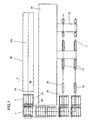
- 50 denotes a system, in its entirety, incorporating a machine 1 for forming containers 2 according to the present invention.
- the system 50 comprises a supporting structure 51 and, associated with this same structure, a forming sector 52 serving to prepare at least one blank 7 from which to fashion a relative container 2, also a shaping sector 53 operating downstream of the forming sector 52, of which the function is to fold the single blanks 7 emerging from the forming sector and establish the shape of the respective folded containers 2 by means of a fixing operation.
- the machine for forming containers according to the present invention is designed to operate in the shaping sector 53 of such a system, as will be described in due course.
- the forming sector 52 comprises a feed station 52a by which a continuous strip 54 of forming material suitable for preserving liquid food products is directed along a predetermined feed path denoted Y.
- the forming material will consist preferably of a multilayer or treated paper material, such as paperboard or cardboard coated with an impermeable and antiseptic film.
- the feed station 52a also comprises a plurality of guide elements, consisting preferably in rollers, serving to establish a first leg of the feed path followed by the forming material that extends externally of the supporting structure 51 of the system 50 along a direction substantially parallel to the longitudinal dimension of the selfsame supporting structure.
- the system 50 can be equipped with a numbering device serving to mark consecutive portions of the forming material coinciding with the single blanks 7.
- the numbering device operates between successive guide elements of the feed station 52a in such a way as to mark the forming material at a stage along the feed path where the strip extends substantially in a horizontal plane.
- the forming sector 53 includes a scoring station 55 positioned downstream of the feed station 52a, by which each portion of the forming material destined to provide a relative blank 7 is impressed with at least one crease line.
- the scoring station 55 is designed to generate a plurality of crease lines, in a single operation, by which the shape of the container 2 being manufactured is marked out on the flat surface of the forming material.
- the scoring station 55 comprises at least one press presenting mutually opposed dies offered to the two faces of the forming material.
- the press will alternate between an idle position in which the two dies are distanced from the forming material interposed between them, and an operating position in which they are brought together forcibly against the forming material in such a way as to generate the aforementioned crease lines.
- the forming sector 53 also comprises a cutting station 56 operating downstream of the scoring station 55, by which the creased forming material is taken up from this same station and divided into successive discrete pieces each constituting a respective blank 7.
- the cutting station 56 comprises at least one blade positioned to operate in close proximity to the scoring station 55 so that the forming material can be cut immediately adjacent to the press.
- the blade In operation, like the press, the blade alternates between an idle position distanced from the forming material, and an operating position of engagement with the selfsame material, in which the strip is cut transversely.
- the blade can be timed to alternate between the idle position and the operating position synchronously with the movement of the press of the scoring station 55 between the relative idle and operating positions, so that the dies and the blade are made to engage the forming material simultaneously.
- the creased and cut blank 7 passes to the shaping sector 53 and is taken up by the machine to which the present invention refers.
- 1 denotes a machine for forming containers 2, in its entirety, embodied in accordance with the present invention.
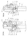
- the machine 1 comprises a first mechanism 3 by means of which to convey a plurality of tubular elements 2a constituting the containers 2.
- tubular elements 2a are advanced by way of a feed station 4 toward the conveying mechanism 3, ordered in single file.
- the tubular elements 2a are prepared by a forming device 5 coinciding with and operating at the feed station 4.
- the forming device 5 presents a gripper element 6 serving to bend the blank 7 of multilayer or treated paper material, typically paperboard or cardboard coated with one of more layers of food-safe material suitable for liquid products.
- the blank is wrapped by the gripper element 6 around a former 8 of shape corresponding to the shape of the tubular element 2a, in such a way that one longitudinal edge of the selfsame blank 7 will overlap the other.
- the forming device 5 also presents a sealer 6a serving to join the longitudinal edges and create the tubular element 2a, and a feed mechanism 9 by which the tubular element 2a is caused to advance along a radial infeed direction A toward the first conveying mechanism 3.
- the machine could also operate utilizing blanks 7 supplied to the feed station 4 in a precreased tubular configuration, collapsed so as to present an essentially flat rhomboidal cross section.
- the system 50 could include a forming device 5 (not part of the present invention) of conventional embodiment embraced by the prior art, comprising a gripper element 6 that can be offered to the two opposite side edges of the precreased tubular blank 7 in such a way as to apply a compressive force and thus cause the flattened profile to expand to a substantially square profile when viewed in section.
- a forming device 5 not part of the present invention
- a gripper element 6 can be offered to the two opposite side edges of the precreased tubular blank 7 in such a way as to apply a compressive force and thus cause the flattened profile to expand to a substantially square profile when viewed in section.
- the first conveying mechanism 3 is disposed facing the feed station 4 and capable of movement between a first operating position in which a single tubular element 2a is taken up from the feed station 4, and a second operating position in which the tubular element 2a is offered to respective first sealing means 10.
- the first conveying mechanism 3 comprises at least one first wheel 11 rotatable in a first feed direction B along a first circular sealing path P' passing through the feed station 4 and the first sealing means 10.
- the first wheel 11 is composed of a central hub 12 rotatable about a respective axis 12a, and a plurality of supporting elements 13 serving to carry the tubular elements 2a.
- the supporting elements 13 project radially from the hub 12, each presenting a first end 13a anchored to the selfsame hub 12, and a second end 13b, opposite to the first, appearing substantially cylindrical in shape and smaller in section than the remainder of the element 13.
- the system comprises two first wheels 11 disposed one alongside the other, each presenting a relative set of supporting elements 13 arranged around the respective hub 12.
- each supporting element 13 presents a substantially parallelepiped geometry complementing the internal shape of the tubular element ⁇ 2a.
- the tubular element 2a is substantially parallelepiped in appearance and of square cross section. Consequently, the supporting element 13 will present a square parallelepiped shape identical to that of the tubular element 2a.
- each tubular element 2a can be fitted over a respective supporting element 13 in such a way that the respective first open end 2b of the selfsame element 2a is positioned to coincide with the second end 13b of the supporting element 13.
- the machine comprises a feed device 14 supplying necks 15 for the containers 2.
- the function of the feed device 14 in question is to place one neck 15 on the second end 13b of each supporting element 13.
- the shape of the second end 13b is matched to the internal geometry of the neck 15, which consists in a tubular body preferably of plastic material, presenting a mouth 15a uppermost and a substantially square base 15b at the end of the body opposite from the mouth 15a.
- the four sides of the base constitute connecting portions 15c offered to the tubular element 2a in positions parallel with corresponding first and second top faces 16 and 17 of the selfsame tubular element 2a.
- the aforementioned first sealing means 10 are positioned along the first sealing path P' and in particular downstream of the feed station 4, relative to the first feed direction B, in such a way as to interact with and close the first open end 2b of each tubular element 2a by fixing the relative neck 15.
- each set of supporting elements 13 is equipped with respective first sealing means 10.
- first sealing means 10 of each wheel 11 consist in a first joining head 10a (not part of the present invention) able to interact with the tubular element 2a in such a way as to seal two connecting portions 15c of the neck 15, positioned on the second end 13b of the supporting element 13, to the two mutually opposed first top faces 16 of the tubular element 2a.
- first sealing means 10 comprise a second joining head 10b (not part of the present invention) operating downstream of the first joining head 10a, relative to the first feed direction B, interacting with the tubular element 2a in such a way as to seal two connecting portions 15c of the neck 15 to the two mutually opposed second top faces 17 of the tubular element 2a.
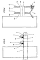
- the first joining head 10a consists in at least two mutually opposed first forming elements 18 (not part of the present invention) capable of movement between a first idle position, distanced from the first top faces 16 of the tubular element 2a ( figure 5a ), and a second operating position in which the first top faces 16 are engaged by the selfsame forming elements 18 and sealed to the respective connecting portions 15c of the neck 15 ( figure 5b ).
- Each first forming element 18 is set in motion by conventional actuator means, which are neither described nor illustrated, and comprises a sealer or welder 19 (not part of the present invention) likewise of conventional type used widely in the manufacture of food containers. More exactly, the sealer or welder 19 might be a heat sealing or an ultrasound or induction welding instrument but in any event will present heatable rectilinear portions 19a arranged in such a way as to present a substantially trapezoidal outline and applicable when in the operating position to respective seal lines 20.
- seal lines 20 are located on the first top faces 16 of the tubular element and along the connecting portions 15c of the neck, describing a substantially trapezoidal outline.
- the first joining head 10a also comprises two mutually opposed first reaction elements 21 (not part of the present invention) capable of movement transversely to the first forming elements 18 between a first idle position distanced from the second top faces 17, assumed when the first forming elements 18 occupy the relative first idle position, and a second operating position of contact with the second top faces 17, assumed when the first forming elements 18 occupy the relative second operating position.
- first reaction elements 21 capable of movement transversely to the first forming elements 18 between a first idle position distanced from the second top faces 17, assumed when the first forming elements 18 occupy the relative first idle position, and a second operating position of contact with the second top faces 17, assumed when the first forming elements 18 occupy the relative second operating position.
- the first forming elements 18 and the first reaction elements 21 function as the jaws of a gripper converging on the tubular element 2a.
- each first reaction element 21 presents a substantially parallelepiped main body 22 comprising a top portion 22a offered to the neck 15 and a bottom portion 22b offered to a corresponding second top face 17.
- the top portion 22a presents a locating portion 23, projecting from the selfsame top portion 22a and presenting a substantially "U"-shaped cross sectional profile internally.
- the locating portion 23 thus embodied is contoured to match the profile of the neck 15, and offered to a top cylindrical portion of the neck 15 near to the mouth 15a.
- each first reaction element 21 presents a bearing surface 24 offered to the respective second top face 17.
- the surface 24 in question comprises a flat central portion 24a positioned below the locating portion 23, and designed to breast with a central surface 17a of the corresponding second top face 17.
- the flat central portion 24a of the bearing surface 24 presents a substantially trapezoidal outline, so that the central surface 17a of the second top face 17 can be invested with a trapezoidal shape.
- each oblique side of the flat central portion 24a presents a respective lateral portion 24b of which the surface is angled relative to that of the central portion 24a, so that the selfsame central portion 24a is caused to project from the bottom portion 22b as discernible in figures 5a and 5b
- the lateral portions 24b present a substantially triangular outline and combine with the heatable rectilinear portions 19a of the sealer 19 to create corresponding fins 25 located along the external corner edges of the tubular element 2a.
- the second joining head 10b consists in at least two mutually opposed second forming elements 26 (not part of the present invention) capable of movement between a first idle position, distanced from the respective second top faces 17 of the tubular element 2a ( figure 6a ), and a second operating position in which the second top faces 17 are engaged by the selfsame forming elements 26 and sealed to the respective connecting portions 15c of the neck 15 ( figure 6b ).
- Each second forming element 26 is set in motion by relative actuator means, and comprises a sealer or welder 27 (not part of the present invention) of conventional type as used widely in the manufacture of food containers. More exactly, the sealer or welder 27 might be a heat sealing or an ultrasound or induction welding instrument.
- the sealer 27 also presents a heatable rectilinear portion 27a such as will engage a respective seal line 20 when the forming element occupies the second operating position.
- the seal line 20 in question corresponds substantially to the area of the join between the second top face 17 and the connecting portion 15c.
- the second joining head 10b also comprises two mutually opposed second reaction elements 28 (not part of the present invention) capable of movement transversely to the second forming elements 26 between a first idle position distanced from the first top faces 16, assumed when the second forming elements 26 occupy the relative first idle position, and a second operating position of contact with the first top faces 16, assumed when the second forming elements 26 occupy the relative second operating position.
- the second forming elements 26 and the second reaction elements 28 are arranged substantially in the same manner as the first forming elements 18 and the first reaction elements 21, with the difference that they are designed to seal two opposite faces of the tubular element 2a not sealed by the first joining head 10a.
- each second reaction element 28 appears identical to the first reaction element 21, with a substantially parallelepiped main body 29 comprising a top portion 29a offered to the neck 15 and a bottom portion 29b offered to the first top faces 16.
- the top portion 29a presents a locating portion 30, projecting from the selfsame portion 29a and presenting a substantially "U"-shaped cross sectional profile internally.
- the locating portion 30 thus embodied is contoured to match the profile of the neck 15, and offered to a top cylindrical portion of the neck 15 near to the mouth 15a.
- each second reaction element 28 presents a bearing surface 31 offered to the respective first top face 16.
- the surface 31 in question comprises a flat central portion 31a positioned below the locating portion 30, and designed to breast with a central surface 16a of the corresponding first top face 16 secured in place previously by the first joining head 10a.
- the flat central portion 31a of the bearing surface 31 presents a substantially trapezoidal outline, so that the central surface 16a of the first top face 16 can be invested with a trapezoidal shape.
- each oblique side of the flat central portion 31a presents a respective lateral portion 31b of which the surface is angled relative to that of the central portion 31a, so that the selfsame central portion 31a is caused to project from the bottom portion 29b as discernible in figures 6a and 6b .
- the lateral portions 31b present a substantially triangular outline and are designed to bear against respective fins 25 located along the external corner edges of the tubular element 2a, in like manner to the corresponding portions of the first reaction elements 21 already described.
- the machine 1 also comprises a second conveying mechanism 32 operating in conjunction with the first conveying mechanism 3, downstream of the first sealing means 10 considered in relation to the feed direction B.
- the second mechanism 32 is capable of movement between a first operating position in which the tubular elements 2a are taken up from the first conveying mechanism 3, and a second operating position in which the tubular elements 2a are offered to respective second sealing means 36.
- the second conveying mechanism 32 comprises a second wheel 33 (not part of the present invention) similar to the first wheel 11 and rotatable in a second feed direction C along a second circular sealing path P" tangential to the first sealing path P' .
- the second sealing path P" passes adjacent to the first conveying mechanism 2 and to the aforementioned second sealing means 36.
- the second wheel 33 comprises a central hub 33a rotatable about a respective axis, and a plurality of holder elements 34 projecting radially from the central hub 33a.
- each holder element 34 presents an essentially tubular appearance and affords an access opening 34a at the end farthest from the hub 33a, also an internal surface matched to the external geometry of the tubular element 2a.
- the single tubular element 2a is insertable into a corresponding holder element 34 in such a way that a second open end 2c, opposite to the first open end 2b, is positioned to coincide with the access opening 34a.
- each holder element 34 accommodates an internal elongated member 35 likewise projecting radially from the hub 33a.
- the elongated member 35 presents a first end 35a anchored to the hub 33a, and a second end 35b opposite to the first end 35a, positioned to coincide with the access opening 34a.
- the machine also comprises a transfer device 60 (not part of the present invention) operating between the first wheel 11 and the second wheel 33 and capable of alternating between a first position, in which it takes up a tubular element 2a facing the second wheel 33 and carried by a relative supporting element 13, and a second position in which the tubular element 2a is placed by the device 60 in a corresponding holder element 34, causing the elongated member 35 to pass through the mouth 15a of the neck 15 and into the tubular element 2a, and positioning the second open end 2c externally of the access opening 34a.
- a transfer device 60 (not part of the present invention) operating between the first wheel 11 and the second wheel 33 and capable of alternating between a first position, in which it takes up a tubular element 2a facing the second wheel 33 and carried by a relative supporting element 13, and a second position in which the tubular element 2a is placed by the device 60 in a corresponding holder element 34, causing the elongated member 35 to pass through the mouth 15a of the neck 15 and into
- the transfer device 60 is not described and illustrated in detail, being of a type widely used in the art field to which the invention relates.
- the device could consist in a set of suction cups positionable against the outer surface of the tubular element 2a and carried by a mechanical arm such as will direct the tubular element 2a into the holder element 34.
- the second sealing means 36 are designed to interact with the second open end 2c of the tubular element 2a, in such a manner as to close the selfsame second end 2c and complete the container 2.
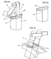
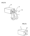
- the second sealing means 36 consist in a joining head 37 (not part of the present invention) able to interact with the second open end 2c of each tubular element 2a, and as a result to unite two mutually opposed sides 38 of the tubular element 2a coinciding with this same end 2c (see figures 7a and 7b ). More precisely, the two sides 38 coincide with two opposite faces of the tubular element 2a and are united in such a way as to bring together two respective top edges 38a extending transversely to the longitudinal dimension of the tubular element 2a as a whole.
- the joining head 37 comprises two folder elements 39 (not part of the present invention) that can be offered to the corresponding sides 38 in such a way as to draw together and match the respective top edges 38a.
- the head 37 also presents a sealer 40 (not part of the present invention) operating on the two edges 38a in such a manner as to secure them one to another.
- the second sealing means 36 also include a press 41 (not part of the present invention) (shown in figure 7c ) located downstream of the joining head 37, considered in relation to the second feed direction C, operating on the joined sides 38 in such a way as to force them toward the hub 33a.
- the effect of the forcing action is to produce a flat base surface extending substantially transverse to the longitudinal dimension of the tubular element.
- the action of the press 41 also generates two opposite end folds 42 projecting laterally beyond the relative side walls of the tubular element 2a and presenting a substantially triangular outline.
- the second sealing means 36 can also be equipped with a first sealer or welder 43 (not part of the present invention) ( figure 7c ) such as will engage seal lines delimiting the end folds 42, thereby joining the two flattened thicknesses of material and creating a bottom surface of the container.
- a first sealer or welder 43 (not part of the present invention) ( figure 7c ) such as will engage seal lines delimiting the end folds 42, thereby joining the two flattened thicknesses of material and creating a bottom surface of the container.
- glue of conventional type.
- the second sealer 45 is embodied as a movable arm 45a capable of vertical movement and directed against the bent end folds 42 at a point coinciding with the second end 35b of the elongated member 35, which is located immediately below the access opening 34a of the holder element 34.
- an outfeed device 46 is also operating downstream of the second sealing means 36, along the second feed direction C, by which each completed container 2 is removed from the corresponding holder element 34 and directed toward further finishing stations.
- Tubular elements 2a prepared initially by the forming device 5 in the manner already described are directed into the feed station 4.
- the tubular elements 2a pass along the infeed direction A ( figure 2 ) and are taken up by the first conveying mechanism 3. More exactly, the tubular elements 2a are taken up onto the wheel 11 in such a way that each supporting element 13 is ensheathed by a respective tubular element 2a. It will be observed that the motion of the wheel 11 is not continuous; rather, the hub is indexed in such a way that the supporting elements 13 are brought into alignment with the feed station 4, then with the first sealing means 10 and thereafter with the second conveying mechanism 32.
- Each tubular element 2a is thus positioned on the relative supporting element 13 with the first open end 2b positioned at the second end 13b of the selfsame element 13, on which a neck 15 will have been positioned previously by the relative feed device 14.
- the tubular element 2a now advances along the first sealing path P' toward the first joining head 10a.
- the first forming elements 18 and reaction elements 21 assume their respective operating positions ( figure 5b ).
- the first forming elements 18 engage the first top faces 16, and the material is secured along the seal lines 20.
- the first reaction elements 21 engage the second top faces 17, with the result that the neck 15 is restrained by the locating portions 23 and aligned with the tubular element 2a, and the central surface 17a is forced to assume the intended trapezoidal outline.
- the shape in question is imparted to the central surface 17a by the flat central portion 21a of the first reaction element 21, of which the projecting profile impresses both the central surface 17a and the two adjoining fins 25 at one and the same time.
- first forming elements 18 and the first reaction elements 21 resume their respective idle positions ( figure 5a ) to release the tubular element 2a, which is advanced toward the second joining head 10b.
- the second forming elements 26 and the second reaction elements 28 now assume their respective operating positions ( figure 6b ).
- the second forming elements 26 engage the previously impressed second top faces 17, so that the seal can be made along the lines 20 connecting the neck 15.
- the second reaction elements 28 engage the first top faces 16, with the result that the neck 15 is restrained by the locating portions 30, and the central surfaces 16a are forced to assume the intended trapezoidal outline.
- the shape in question is imparted to the central surface 16a by the flat central portion 31a of the second reaction element 28, of which the projecting profile impresses both the central surface 16a and the two adjoining fins 25 at one and the same time.
- the tubular elements are directed toward the transfer device 60.
- the partly formed tubular elements 2a are directed each into a relative holder device 34 of the second conveying mechanism 33, with the elongated member 35 inserted through the mouth 15a of the neck 15.
- the tubular element 2a is positioned internally of the corresponding holder element 34 with the neck 15 positioned at the first end 35a of the elongated member 35.
- tubular elements 2a are advanced along the sealing path P" in the second feed direction C toward the second sealing means 36.
- the tubular elements 2a pass beneath the joining head 37, by which the aforementioned sides 38 are drawn together and bent so as to unite the respective top edges 38a.
- the sealer 40 passes along the full length of the top edges 38a, securing them one to another ( figure 7a ).
- the press 41 will force the joined sides 38 against the wheel 33 in such a way as to generate a flat surface ( figure 7c ) extending substantially transverse to the longitudinal dimension of the tubular element 2a and presenting the two end folds 42.
- the first sealer or welder 43 following the press 41 is applied to seal lines positioned to delimit the end folds 42, so that these can be united to create the square base of the container 2.
- the arm 45a of the second sealer 45 will engage the overlapped end folds 42, impinging on the second end 35a of the elongated member 35 located internally of the tubular element 2a and in alignment with the point at which the end folds 42 are overlapped.
- the tubular element 2a is thus closed at both ends 2b and 2c to complete the container 2.
- the container 2 is now conveyed to the outfeed device 46, where it is removed from the holder element 34 and advanced toward further finishing stations.
- the machine 1 is designed to form the container 1 in its entirety.
- the tubular element 2a is first assembled and then the bottom end then closed, so that there are no further passages or movements of the tubular element needed to form the container 2.
- the machine 1 can be made more compact and suitable for use in any given system for forming containers used in the packaging of food and similar products.
Landscapes
- Making Paper Articles (AREA)
- Closing Of Containers (AREA)
- Supplying Of Containers To The Packaging Station (AREA)
- Container Filling Or Packaging Operations (AREA)
- Package Closures (AREA)
- Commercial Cooking Devices (AREA)
- General Preparation And Processing Of Foods (AREA)
- Noodles (AREA)
- Vending Machines For Individual Products (AREA)
- Basic Packing Technique (AREA)
Applications Claiming Priority (3)
| Application Number | Priority Date | Filing Date | Title |
|---|---|---|---|
| IT2002BO000486A ITBO20020486A1 (it) | 2002-07-25 | 2002-07-25 | Macchina per formare contenitori , in particolare contenitori per prodotti alimentari |
| ITBO20020486 | 2002-07-25 | ||
| PCT/IB2003/003160 WO2004011238A2 (en) | 2002-07-25 | 2003-07-14 | Method and machine for forming containers, in particular containers for food products |
Publications (2)
| Publication Number | Publication Date |
|---|---|
| EP1554111A2 EP1554111A2 (en) | 2005-07-20 |
| EP1554111B1 true EP1554111B1 (en) | 2011-04-06 |
Family
ID=11440331
Family Applications (1)
| Application Number | Title | Priority Date | Filing Date |
|---|---|---|---|
| EP03741008A Expired - Lifetime EP1554111B1 (en) | 2002-07-25 | 2003-07-14 | Methode and machine for forming containers, in particular containers for food products |
Country Status (12)
| Country | Link |
|---|---|
| US (1) | US7090630B2 (pt) |
| EP (1) | EP1554111B1 (pt) |
| JP (1) | JP4435683B2 (pt) |
| CN (1) | CN100496961C (pt) |
| AT (1) | ATE504427T1 (pt) |
| AU (1) | AU2003281761A1 (pt) |
| BR (1) | BR0305625B1 (pt) |
| DE (1) | DE60336669D1 (pt) |
| ES (1) | ES2364457T3 (pt) |
| IT (1) | ITBO20020486A1 (pt) |
| RU (1) | RU2318669C2 (pt) |
| WO (1) | WO2004011238A2 (pt) |
Cited By (1)
| Publication number | Priority date | Publication date | Assignee | Title |
|---|---|---|---|---|
| DE102013221721A1 (de) | 2013-10-25 | 2015-04-30 | Robert Bosch Gmbh | Behälter, insbesondere für Flüssigkeiten |
Families Citing this family (16)
| Publication number | Priority date | Publication date | Assignee | Title |
|---|---|---|---|---|
| ITBO20040312A1 (it) * | 2004-05-18 | 2004-08-18 | Azionaria Costruzioni Acma Spa | Macchina per formare contenitori. |
| JP4566628B2 (ja) * | 2004-06-25 | 2010-10-20 | 株式会社フジシールインターナショナル | スパウト装着方法及びスパウト装着装置 |
| ITBO20040491A1 (it) * | 2004-07-30 | 2004-10-30 | Aetna Group Spa | Macchina e metodo per la formazione di spezzoni tubolari di film da imballaggio |
| EP1826125B1 (en) * | 2006-02-28 | 2009-10-07 | Tetra Laval Holdings & Finance SA | Folding assembly and method for producing a gable portion of a sealed package of a pourable food product |
| DE602006003407D1 (de) * | 2006-02-28 | 2008-12-11 | Tetra Laval Holdings & Finance | Biegevorrichtung zur Formung von versiegelte Verpackungen mit fliessfähigen Nahrungsmittel |
| SE529720C2 (sv) * | 2006-03-10 | 2007-11-06 | Tetra Laval Holdings & Finance | Metod att tillverka en förpackning |
| EP1990184A1 (de) * | 2007-05-11 | 2008-11-12 | Michael Hörauf Maschinenfabrik GmbH u. Co. KG | Vorrichtung zum Herstellen einer konischen Hülse und/oder eines Papierbechers |
| US7976333B2 (en) * | 2009-09-29 | 2011-07-12 | Flex-Cable | Laminar electrical connector |
| DE102010050502A1 (de) * | 2010-11-08 | 2012-05-10 | Sig Technology Ag | Vorrichtung und Verfahren zur Herstellung einer Verpackung |
| JP2014080013A (ja) * | 2012-09-26 | 2014-05-08 | Toyo Jidoki Co Ltd | スパウト付き袋の製造方法及び装置 |
| GB201319551D0 (en) * | 2013-11-05 | 2013-12-18 | Elopak Systems | Improvements in or relating to packaging |
| US10919252B2 (en) * | 2016-01-19 | 2021-02-16 | S. C. Johnson & Son, Inc. | System and process for making a pouch or container |
| US10953621B2 (en) * | 2016-03-18 | 2021-03-23 | Tci Manufacturing Inc. | System and method for manufacturing a flexible intermediate bulk container |
| DE102018008483B3 (de) * | 2018-10-30 | 2020-01-30 | Benhil Gmbh | Verfahren zum Verpacken von portionierten, im Verarbeitungszustand flüssigen oder pastösen Produkten und Verpackungsmaschine zur Durchführung eines solchen Verfahrens |
| WO2021156816A1 (en) * | 2020-02-07 | 2021-08-12 | Sasib S.P.A. | Manufacturing machine and manufacturing method for the production of a tubular element, in particular for a smoking article |
| FR3121919B1 (fr) * | 2021-04-16 | 2023-03-31 | Synerlink | Appareils de manutention dans une machine traitant des récipients |
Family Cites Families (16)
| Publication number | Priority date | Publication date | Assignee | Title |
|---|---|---|---|---|
| CH413339A (de) | 1964-09-03 | 1966-05-15 | Continental Can Co | Verfahren zur Herstellung eines Beutels aus Kunststoff-Folie, nach diesem Verfahren hergestellter Beutel und Apparat zur Durchführung des Verfahrens |
| US3486423A (en) * | 1966-06-03 | 1969-12-30 | Illinois Creamery Supply Co | Machine for automatically forming,filling,closing and sealing plastic coated gable top cartons of paperboard or the like |
| SE335090B (pt) * | 1968-10-30 | 1971-05-10 | Tetra Pak Int | |
| DE3163709D1 (en) * | 1980-02-22 | 1984-06-28 | Dainippon Printing Co Ltd | Method and apparatus for the fabrication of a bag-in-box package |
| DE3043134C2 (de) * | 1980-11-15 | 1986-06-19 | Altstädter Verpackungsvertriebs Gesellschaft mbH, 6102 Pfungstadt | Packung für fließfähige Füllgüter |
| DE3526602A1 (de) * | 1985-07-25 | 1987-01-29 | Bosch Gmbh Robert | Verfahren zum herstellen eines verpackungsbehaelters mit einem rberdruckventil |
| SE457874B (sv) * | 1986-04-18 | 1989-02-06 | Tetra Pak Ab | Anordning vid foerpackningsmaskin |
| US4788811A (en) * | 1986-05-17 | 1988-12-06 | Dai Nippon Insatsu Kabushiki Kaisha | Process and apparatus for assembling and liquor-charging of packages of paper and the like |
| JPH0741901B2 (ja) * | 1989-09-06 | 1995-05-10 | 凸版印刷株式会社 | 充填シール機 |
| DE3942319A1 (de) * | 1989-12-21 | 1991-06-27 | Pkl Verpackungssysteme Gmbh | Behaelter fuer fluessigkeiten und schuettgueter in form einer im wesentlichen quaderfoermigen faltschachtel aus karton, insbesondere aus kartonkunststoffmehrschichtverbundmaterial |
| JPH06263107A (ja) * | 1993-03-12 | 1994-09-20 | Dainippon Printing Co Ltd | 紙容器充填密封装置 |
| JP2956450B2 (ja) * | 1993-10-19 | 1999-10-04 | 凸版印刷株式会社 | 流体収納容器の製造方法 |
| US5829228A (en) | 1996-04-25 | 1998-11-03 | Tetra Laval Holdings & Finance, Sa | Method and apparatus for forming the top of a container |
| DE19726215A1 (de) * | 1997-06-20 | 1998-12-24 | Hoerauf Michael Maschf | Vorrichtung zum Herstellen einer Papierdose |
| JP2002510256A (ja) * | 1998-10-02 | 2002-04-02 | テトラ ラバル ホールデイングス エ フイナンス ソシエテ アノニム | カートンの頂部を形成するための方法および装置 |
| JP4788086B2 (ja) * | 2001-09-07 | 2011-10-05 | 四国化工機株式会社 | 包装機械 |
-
2002
- 2002-07-25 IT IT2002BO000486A patent/ITBO20020486A1/it unknown
-
2003
- 2003-07-14 AT AT03741008T patent/ATE504427T1/de active
- 2003-07-14 JP JP2004524013A patent/JP4435683B2/ja not_active Expired - Fee Related
- 2003-07-14 ES ES03741008T patent/ES2364457T3/es not_active Expired - Lifetime
- 2003-07-14 DE DE60336669T patent/DE60336669D1/de not_active Expired - Lifetime
- 2003-07-14 US US10/489,965 patent/US7090630B2/en not_active Expired - Lifetime
- 2003-07-14 EP EP03741008A patent/EP1554111B1/en not_active Expired - Lifetime
- 2003-07-14 WO PCT/IB2003/003160 patent/WO2004011238A2/en active Application Filing
- 2003-07-14 RU RU2005101320/11A patent/RU2318669C2/ru not_active IP Right Cessation
- 2003-07-14 BR BRPI0305625-2A patent/BR0305625B1/pt not_active IP Right Cessation
- 2003-07-14 CN CNB038179016A patent/CN100496961C/zh not_active Expired - Fee Related
- 2003-07-14 AU AU2003281761A patent/AU2003281761A1/en not_active Abandoned
Cited By (1)
| Publication number | Priority date | Publication date | Assignee | Title |
|---|---|---|---|---|
| DE102013221721A1 (de) | 2013-10-25 | 2015-04-30 | Robert Bosch Gmbh | Behälter, insbesondere für Flüssigkeiten |
Also Published As
| Publication number | Publication date |
|---|---|
| RU2005101320A (ru) | 2005-10-10 |
| CN1671541A (zh) | 2005-09-21 |
| ITBO20020486A1 (it) | 2004-01-26 |
| AU2003281761A1 (en) | 2004-02-16 |
| AU2003281761A8 (en) | 2004-02-16 |
| BR0305625B1 (pt) | 2011-06-28 |
| US20040235632A1 (en) | 2004-11-25 |
| JP2005533687A (ja) | 2005-11-10 |
| CN100496961C (zh) | 2009-06-10 |
| WO2004011238A3 (en) | 2004-05-21 |
| BR0305625A (pt) | 2004-10-19 |
| DE60336669D1 (de) | 2011-05-19 |
| ITBO20020486A0 (it) | 2002-07-25 |
| JP4435683B2 (ja) | 2010-03-24 |
| ATE504427T1 (de) | 2011-04-15 |
| WO2004011238A2 (en) | 2004-02-05 |
| EP1554111A2 (en) | 2005-07-20 |
| ES2364457T3 (es) | 2011-09-02 |
| US7090630B2 (en) | 2006-08-15 |
| RU2318669C2 (ru) | 2008-03-10 |
Similar Documents
| Publication | Publication Date | Title |
|---|---|---|
| EP1554111B1 (en) | Methode and machine for forming containers, in particular containers for food products | |
| US6606840B2 (en) | Process and apparatus for producing (cigarette) packs | |
| EP2922694B1 (en) | Method and system for manufacturing bags | |
| CN109153467A (zh) | 由双侧打开的包装套形成单侧打开的包装体的方法和装置 | |
| US7686753B2 (en) | Bottom finishing station components for a cup making machine | |
| JPS58203839A (ja) | 流体用容器 | |
| KR20110091874A (ko) | 용기-형 박층 패키징을 제조하기 위한 방법 및 장치 | |
| NO155435B (no) | Fremgangsmaate og apparat for tildanning av en forsegling mellom lag i en beholder av termoplastbelagt pappmateriale. | |
| EP1554112B1 (en) | A system for forming containers, in particular containers for food products | |
| CN102245477B (zh) | 用于将开启装置应用在能灌装到包装材料管中的食品的包装上的单元 | |
| CN104136327A (zh) | 用于可倾倒食品包装机的折叠单元 | |
| ES2823487T3 (es) | Procedimiento y máquina de ensamblaje de cuerpos tubulares rígidos hechos de material de cartón con una estructura de cierre | |
| US5609556A (en) | Method and apparatus for manufacturing bags with strap-shaped carrying handles | |
| EP1588950B1 (en) | A method for forming a handle on film used to produce packs of rolls of products | |
| EP1763434B1 (en) | A machine for forming containers for liquids | |
| US4646507A (en) | Machine for making packs for flowing material | |
| JP2548916B2 (ja) | 液体用パツケ−ジの製造方法および装置 | |
| US7329216B2 (en) | System for manufacturing containers | |
| WO2007071698A1 (en) | Improvements in or relating to packaging | |
| US6810640B1 (en) | Methods for producing a composite packing and a composite packing produced according to said method | |
| JPH02277637A (ja) | 管状梱包用品本体の製造方法、該方法によって製造した梱包用品並びに該方法を実施するための装置 | |
| CA1178410A (en) | Pack for fluid filling materials with reclosable opening device | |
| JP2022534512A (ja) | 傾斜ゲーブルを有する包装体のゲーブル面を後成形するためのデバイスおよび方法 | |
| MXPA01009503A (en) | Method for producing a composite packing and a composite packing produced according to said method |
Legal Events
| Date | Code | Title | Description |
|---|---|---|---|
| PUAI | Public reference made under article 153(3) epc to a published international application that has entered the european phase |
Free format text: ORIGINAL CODE: 0009012 |
|
| 17P | Request for examination filed |
Effective date: 20050209 |
|
| AK | Designated contracting states |
Kind code of ref document: A2 Designated state(s): AT BE BG CH CY CZ DE DK EE ES FI FR GB GR HU IE IT LI LU MC NL PT RO SE SI SK TR |
|
| AX | Request for extension of the european patent |
Extension state: AL LT LV MK |
|
| DAX | Request for extension of the european patent (deleted) | ||
| 17Q | First examination report despatched |
Effective date: 20090720 |
|
| GRAP | Despatch of communication of intention to grant a patent |
Free format text: ORIGINAL CODE: EPIDOSNIGR1 |
|
| RIN1 | Information on inventor provided before grant (corrected) |
Inventor name: CAVALLARI, STEFANO Inventor name: GHIOTTI, ROBERTO Inventor name: BOLDRINI, FULVIO |
|
| GRAS | Grant fee paid |
Free format text: ORIGINAL CODE: EPIDOSNIGR3 |
|
| GRAL | Information related to payment of fee for publishing/printing deleted |
Free format text: ORIGINAL CODE: EPIDOSDIGR3 |
|
| GRAS | Grant fee paid |
Free format text: ORIGINAL CODE: EPIDOSNIGR3 |
|
| RAP1 | Party data changed (applicant data changed or rights of an application transferred) |
Owner name: SIG TECHNOLOGY AG |
|
| GRAA | (expected) grant |
Free format text: ORIGINAL CODE: 0009210 |
|
| AK | Designated contracting states |
Kind code of ref document: B1 Designated state(s): AT BE BG CH CY CZ DE DK EE ES FI FR GB GR HU IE IT LI LU MC NL PT RO SE SI SK TR |
|
| REG | Reference to a national code |
Ref country code: GB Ref legal event code: FG4D |
|
| REG | Reference to a national code |
Ref country code: CH Ref legal event code: EP |
|
| REG | Reference to a national code |
Ref country code: IE Ref legal event code: FG4D |
|
| REF | Corresponds to: |
Ref document number: 60336669 Country of ref document: DE Date of ref document: 20110519 Kind code of ref document: P |
|
| REG | Reference to a national code |
Ref country code: DE Ref legal event code: R096 Ref document number: 60336669 Country of ref document: DE Effective date: 20110519 |
|
| REG | Reference to a national code |
Ref country code: NL Ref legal event code: T3 |
|
| REG | Reference to a national code |
Ref country code: GR Ref legal event code: EP Ref document number: 20110401364 Country of ref document: GR Effective date: 20110714 |
|
| PG25 | Lapsed in a contracting state [announced via postgrant information from national office to epo] |
Ref country code: SI Free format text: LAPSE BECAUSE OF FAILURE TO SUBMIT A TRANSLATION OF THE DESCRIPTION OR TO PAY THE FEE WITHIN THE PRESCRIBED TIME-LIMIT Effective date: 20110406 |
|
| REG | Reference to a national code |
Ref country code: ES Ref legal event code: FG2A Ref document number: 2364457 Country of ref document: ES Kind code of ref document: T3 Effective date: 20110902 |
|
| PG25 | Lapsed in a contracting state [announced via postgrant information from national office to epo] |
Ref country code: PT Free format text: LAPSE BECAUSE OF FAILURE TO SUBMIT A TRANSLATION OF THE DESCRIPTION OR TO PAY THE FEE WITHIN THE PRESCRIBED TIME-LIMIT Effective date: 20110808 Ref country code: SE Free format text: LAPSE BECAUSE OF FAILURE TO SUBMIT A TRANSLATION OF THE DESCRIPTION OR TO PAY THE FEE WITHIN THE PRESCRIBED TIME-LIMIT Effective date: 20110406 |
|
| PG25 | Lapsed in a contracting state [announced via postgrant information from national office to epo] |
Ref country code: FI Free format text: LAPSE BECAUSE OF FAILURE TO SUBMIT A TRANSLATION OF THE DESCRIPTION OR TO PAY THE FEE WITHIN THE PRESCRIBED TIME-LIMIT Effective date: 20110406 Ref country code: CY Free format text: LAPSE BECAUSE OF FAILURE TO SUBMIT A TRANSLATION OF THE DESCRIPTION OR TO PAY THE FEE WITHIN THE PRESCRIBED TIME-LIMIT Effective date: 20110406 Ref country code: BE Free format text: LAPSE BECAUSE OF FAILURE TO SUBMIT A TRANSLATION OF THE DESCRIPTION OR TO PAY THE FEE WITHIN THE PRESCRIBED TIME-LIMIT Effective date: 20110406 |
|
| PG25 | Lapsed in a contracting state [announced via postgrant information from national office to epo] |
Ref country code: EE Free format text: LAPSE BECAUSE OF FAILURE TO SUBMIT A TRANSLATION OF THE DESCRIPTION OR TO PAY THE FEE WITHIN THE PRESCRIBED TIME-LIMIT Effective date: 20110406 Ref country code: CZ Free format text: LAPSE BECAUSE OF FAILURE TO SUBMIT A TRANSLATION OF THE DESCRIPTION OR TO PAY THE FEE WITHIN THE PRESCRIBED TIME-LIMIT Effective date: 20110406 |
|
| PLBE | No opposition filed within time limit |
Free format text: ORIGINAL CODE: 0009261 |
|
| STAA | Information on the status of an ep patent application or granted ep patent |
Free format text: STATUS: NO OPPOSITION FILED WITHIN TIME LIMIT |
|
| PG25 | Lapsed in a contracting state [announced via postgrant information from national office to epo] |
Ref country code: SK Free format text: LAPSE BECAUSE OF FAILURE TO SUBMIT A TRANSLATION OF THE DESCRIPTION OR TO PAY THE FEE WITHIN THE PRESCRIBED TIME-LIMIT Effective date: 20110406 Ref country code: MC Free format text: LAPSE BECAUSE OF NON-PAYMENT OF DUE FEES Effective date: 20110731 Ref country code: DK Free format text: LAPSE BECAUSE OF FAILURE TO SUBMIT A TRANSLATION OF THE DESCRIPTION OR TO PAY THE FEE WITHIN THE PRESCRIBED TIME-LIMIT Effective date: 20110406 Ref country code: RO Free format text: LAPSE BECAUSE OF FAILURE TO SUBMIT A TRANSLATION OF THE DESCRIPTION OR TO PAY THE FEE WITHIN THE PRESCRIBED TIME-LIMIT Effective date: 20110406 |
|
| REG | Reference to a national code |
Ref country code: CH Ref legal event code: PL |
|
| 26N | No opposition filed |
Effective date: 20120110 |
|
| REG | Reference to a national code |
Ref country code: IE Ref legal event code: MM4A |
|
| PG25 | Lapsed in a contracting state [announced via postgrant information from national office to epo] |
Ref country code: CH Free format text: LAPSE BECAUSE OF NON-PAYMENT OF DUE FEES Effective date: 20110731 Ref country code: LI Free format text: LAPSE BECAUSE OF NON-PAYMENT OF DUE FEES Effective date: 20110731 |
|
| REG | Reference to a national code |
Ref country code: DE Ref legal event code: R097 Ref document number: 60336669 Country of ref document: DE Effective date: 20120110 |
|
| PG25 | Lapsed in a contracting state [announced via postgrant information from national office to epo] |
Ref country code: IE Free format text: LAPSE BECAUSE OF NON-PAYMENT OF DUE FEES Effective date: 20110714 |
|
| PG25 | Lapsed in a contracting state [announced via postgrant information from national office to epo] |
Ref country code: LU Free format text: LAPSE BECAUSE OF NON-PAYMENT OF DUE FEES Effective date: 20110714 |
|
| PG25 | Lapsed in a contracting state [announced via postgrant information from national office to epo] |
Ref country code: BG Free format text: LAPSE BECAUSE OF FAILURE TO SUBMIT A TRANSLATION OF THE DESCRIPTION OR TO PAY THE FEE WITHIN THE PRESCRIBED TIME-LIMIT Effective date: 20110706 |
|
| PG25 | Lapsed in a contracting state [announced via postgrant information from national office to epo] |
Ref country code: HU Free format text: LAPSE BECAUSE OF FAILURE TO SUBMIT A TRANSLATION OF THE DESCRIPTION OR TO PAY THE FEE WITHIN THE PRESCRIBED TIME-LIMIT Effective date: 20110406 |
|
| REG | Reference to a national code |
Ref country code: FR Ref legal event code: PLFP Year of fee payment: 14 |
|
| REG | Reference to a national code |
Ref country code: DE Ref legal event code: R079 Ref document number: 60336669 Country of ref document: DE Free format text: PREVIOUS MAIN CLASS: B31B0001840000 Ipc: B31B0050840000 |
|
| REG | Reference to a national code |
Ref country code: FR Ref legal event code: PLFP Year of fee payment: 15 |
|
| PGFP | Annual fee paid to national office [announced via postgrant information from national office to epo] |
Ref country code: TR Payment date: 20170629 Year of fee payment: 15 Ref country code: NL Payment date: 20170725 Year of fee payment: 15 |
|
| PGFP | Annual fee paid to national office [announced via postgrant information from national office to epo] |
Ref country code: GR Payment date: 20170725 Year of fee payment: 15 |
|
| PGFP | Annual fee paid to national office [announced via postgrant information from national office to epo] |
Ref country code: AT Payment date: 20170727 Year of fee payment: 15 |
|
| REG | Reference to a national code |
Ref country code: FR Ref legal event code: PLFP Year of fee payment: 16 |
|
| REG | Reference to a national code |
Ref country code: NL Ref legal event code: MM Effective date: 20180801 |
|
| REG | Reference to a national code |
Ref country code: AT Ref legal event code: MM01 Ref document number: 504427 Country of ref document: AT Kind code of ref document: T Effective date: 20180714 |
|
| PG25 | Lapsed in a contracting state [announced via postgrant information from national office to epo] |
Ref country code: AT Free format text: LAPSE BECAUSE OF NON-PAYMENT OF DUE FEES Effective date: 20180714 |
|
| PG25 | Lapsed in a contracting state [announced via postgrant information from national office to epo] |
Ref country code: GR Free format text: LAPSE BECAUSE OF NON-PAYMENT OF DUE FEES Effective date: 20190207 Ref country code: NL Free format text: LAPSE BECAUSE OF NON-PAYMENT OF DUE FEES Effective date: 20180801 |
|
| PGFP | Annual fee paid to national office [announced via postgrant information from national office to epo] |
Ref country code: ES Payment date: 20190826 Year of fee payment: 17 Ref country code: IT Payment date: 20190725 Year of fee payment: 17 Ref country code: FR Payment date: 20190725 Year of fee payment: 17 |
|
| PGFP | Annual fee paid to national office [announced via postgrant information from national office to epo] |
Ref country code: GB Payment date: 20190729 Year of fee payment: 17 |
|
| PGFP | Annual fee paid to national office [announced via postgrant information from national office to epo] |
Ref country code: DE Payment date: 20190930 Year of fee payment: 17 |
|
| REG | Reference to a national code |
Ref country code: DE Ref legal event code: R119 Ref document number: 60336669 Country of ref document: DE |
|
| GBPC | Gb: european patent ceased through non-payment of renewal fee |
Effective date: 20200714 |
|
| PG25 | Lapsed in a contracting state [announced via postgrant information from national office to epo] |
Ref country code: GB Free format text: LAPSE BECAUSE OF NON-PAYMENT OF DUE FEES Effective date: 20200714 Ref country code: FR Free format text: LAPSE BECAUSE OF NON-PAYMENT OF DUE FEES Effective date: 20200731 |
|
| PG25 | Lapsed in a contracting state [announced via postgrant information from national office to epo] |
Ref country code: DE Free format text: LAPSE BECAUSE OF NON-PAYMENT OF DUE FEES Effective date: 20210202 |
|
| PG25 | Lapsed in a contracting state [announced via postgrant information from national office to epo] |
Ref country code: IT Free format text: LAPSE BECAUSE OF NON-PAYMENT OF DUE FEES Effective date: 20200714 |
|
| REG | Reference to a national code |
Ref country code: ES Ref legal event code: FD2A Effective date: 20211203 |
|
| PG25 | Lapsed in a contracting state [announced via postgrant information from national office to epo] |
Ref country code: ES Free format text: LAPSE BECAUSE OF NON-PAYMENT OF DUE FEES Effective date: 20200715 |
|
| PG25 | Lapsed in a contracting state [announced via postgrant information from national office to epo] |
Ref country code: TR Free format text: LAPSE BECAUSE OF NON-PAYMENT OF DUE FEES Effective date: 20180714 |