EP1550787A1 - Dispositif ecran a enroulement automatique - Google Patents
Dispositif ecran a enroulement automatique Download PDFInfo
- Publication number
- EP1550787A1 EP1550787A1 EP03751357A EP03751357A EP1550787A1 EP 1550787 A1 EP1550787 A1 EP 1550787A1 EP 03751357 A EP03751357 A EP 03751357A EP 03751357 A EP03751357 A EP 03751357A EP 1550787 A1 EP1550787 A1 EP 1550787A1
- Authority
- EP
- European Patent Office
- Prior art keywords
- winding
- winding shaft
- damper
- shaft
- screen
- Prior art date
- Legal status (The legal status is an assumption and is not a legal conclusion. Google has not performed a legal analysis and makes no representation as to the accuracy of the status listed.)
- Granted
Links
Images


Classifications
-
- E—FIXED CONSTRUCTIONS
- E06—DOORS, WINDOWS, SHUTTERS, OR ROLLER BLINDS IN GENERAL; LADDERS
- E06B—FIXED OR MOVABLE CLOSURES FOR OPENINGS IN BUILDINGS, VEHICLES, FENCES OR LIKE ENCLOSURES IN GENERAL, e.g. DOORS, WINDOWS, BLINDS, GATES
- E06B9/00—Screening or protective devices for wall or similar openings, with or without operating or securing mechanisms; Closures of similar construction
- E06B9/52—Devices affording protection against insects, e.g. fly screens; Mesh windows for other purposes
- E06B9/54—Roller fly screens
- E06B2009/543—Horizontally moving screens
-
- E—FIXED CONSTRUCTIONS
- E06—DOORS, WINDOWS, SHUTTERS, OR ROLLER BLINDS IN GENERAL; LADDERS
- E06B—FIXED OR MOVABLE CLOSURES FOR OPENINGS IN BUILDINGS, VEHICLES, FENCES OR LIKE ENCLOSURES IN GENERAL, e.g. DOORS, WINDOWS, BLINDS, GATES
- E06B9/00—Screening or protective devices for wall or similar openings, with or without operating or securing mechanisms; Closures of similar construction
- E06B9/56—Operating, guiding or securing devices or arrangements for roll-type closures; Spring drums; Tape drums; Counterweighting arrangements therefor
- E06B9/80—Safety measures against dropping or unauthorised opening; Braking or immobilising devices; Devices for limiting unrolling
- E06B2009/807—Brakes preventing fast screen movement
- E06B2009/808—Fluid brakes
Definitions
- the present invention relates to an automatic winding screen device for dust-proof, light exclusion, thermal insulation, and insect proof, and more specifically it relates to an automatic winding screen device using a rotational biassing force due to the rotation of a coil spring housed within a winding shaft as a power source for winding the screen and having a damper for absorbing impact and collision noise produced during winding with the coil spring.
- a screen device has been widely known in that a screen is wound around a winding shaft having a coil spring as a power source while an open/close operation frame is attached at the extremity of the screen for automatically winding the screen.
- the screen is wound by a rotational biassing force due to the rotation of a coil spring, so that the winding speed is increased upon completion of the winding, and the operation frame attached to the extremity of the screen produces large impact upon colliding with a winding box, which may make large collision sound.
- a damper is provided for suppressing the increase in the winding speed (see Japanese Unexamined Patent Application Publication No. 2003-106076, for example).
- the rotational force of the winding shaft is always transmitted to the damper regardless of the rotational direction of the winding shaft, and by a one-way clutch housed in the damper, a resistance due to the damper is applied to the winding shaft during winding the screen around the winding shaft while during rotating the winding shaft in the direction unwinding the screen, the resistance is not applied thereto, enabling the screen to be easily unwound.
- the one-way clutch houses the damper therein, also in the case where the winding shaft is rotated in the direction unwinding the screen, a slight resistance cannot avoid to be applied to the unwinding operation.
- a slight resistance cannot avoid to be applied to the unwinding operation.
- an oil damper there is a resistance due to friction between a rubber packing for preventing oil leakage from the inside of the damper and a shaft penetrating the packing, so that a problem arises in that the unwinding operation slightly becomes heavy.
- the damper is for reducing the winding force of the coil spring for winding the screen, the winding force is extremely reduced in a state that wind is acted on the screen, for example, in comparison with the case where the damper is not provided, so that the winding may be difficult to be conducted depending on the circumstances.
- an automatic winding screen device includes a winding box to which the winding shaft is rotatably supported, the coil spring being fixed to a bracket at one end of the winding box; a spring support seat non-rotatably fixed to the winding shaft, the other end of the coil spring being attached to the spring support seat; a fixed shaft fixed to the bracket of the winding box; and a damper disposed between the fixed shaft and the winding shaft for applying a braking force to the winding shaft, wherein on the fixed shaft, a one-way clutch mechanism is interposed between the damper and the winding shaft, the one-way clutch disconnecting the damper from the winding shaft when the screen is unwound against the rotational biassing force of the coil spring while connecting the damper and the winding shaft at least at a later stage of winding when the winding shaft rotates in a direction causing winding of the screen therearound.
- the one-way clutch mechanism is provided between the damper on the fixed shaft fixed to the winding box and the winding shaft for connecting the damper to the winding shaft when the screen is wound so that the rotation of the winding shaft is not transmitted to the damper with the one-way clutch mechanism, upon unwinding the screen, a resistance force due to friction within the damper is not applied thereto, reducing the resistance during unwinding the screen as small as possible, so that the screen can be unwound lightly further than in a conventional case where the one-way clutch mechanism is housed in the damper.
- the one-way clutch mechanism in the automatic winding screen device may includes a damper-side clutch piece disposed on the fixed shaft that is fixed to the winding box with the damper therebetween and a winding shaft-side clutch piece rotatably fitted on a support shaft disposed in the damper-side clutch piece, the winding shaft-side clutch piece rotating together with the winding shaft and also being slidable along the axial direction of the winding shaft, wherein between both the clutch pieces, clutch teeth may be provided, the clutch teeth being disengaged when the winding shaft is rotated in a direction unwinding the screen while being mated each other when the winding shaft is rotated in a direction winding the screen, and wherein urging means may be provided for urging the winding shaft-side clutch piece towards the damper-side clutch piece such that both clutch teeth are mated with each other.
- the one-way clutch mechanism can be simply structured.
- the one-way clutch mechanism may include a damper-side clutch piece disposed on the fixed shaft that is fixed to the winding box with the damper therebetween and a winding shaft-side clutch piece connected to a support shaft disposed in the damper-side clutch piece with a spirally operating mechanism therebetween, the winding shaft-side clutch piece rotating together with the winding shaft and also being slidable along the axial direction of the winding shaft, wherein the spirally operating mechanism may be structured so that the winding shaft-side clutch piece rotates about the support shaft, the winding shaft-side clutch piece being driven in a direction away from the damper-side clutch piece on rotation of the winding shaft when the winding shaft is rotated in a direction unwinding the screen while being driven in a direction approaching the damper-side clutch piece when the winding shaft is rotated in a direction winding the screen therearound, and wherein both clutch pieces may be provided with clutch teeth which are engaged when the clutch pieces abut each other.
- a braking force due to the damper is applied to the winding shaft at an arbitrary time and a force winding the screen due to the coil spring is not reduced by the braking force until at the time so as to be effectively operated.
- the spirally operating mechanism may comprise screws mated with each other and respectively disposed on the support shaft in the damper-side clutch piece and on the winding shaft-side clutch piece; however, the mechanism is not limited to this, and a thread groove and an extrusion element such as a pin may be used, for example.
- the spirally operating mechanism disposed between the winding shaft-side clutch piece and the support shaft is arranged to be able to drive the winding shaft-side clutch piece in a direction towards the damper-side clutch piece from winding of the screen starts until the time that the damper is operated by the mutual connection of the clutch pieces so as to start reducing the speed of the screen, and wherein on the support shaft, an idling region is provided for idling the winding shaft-side clutch piece relative to the support shaft therein when the winding shaft-side clutch piece exceeds an operational range of the spirally operating mechanism during unwinding of the screen.
- urging means may be provided for urging the winding shaft-side clutch piece disposed in the idling region on the support shaft towards the spirally operating mechanism.
- the standing depth of the support shaft is adjustable relative to the damper-side clutch piece so that a time that the damper starts operating, i.e., a time starting to reduce the speed of the winding shaft, is made adjustable.
- the one-way clutch mechanism may include a damper-side clutch piece disposed on the fixed shaft which is fixed to the winding box with the damper therebetween, a winding shaft-side clutch piece rotating together with the winding shaft and also being slidable along the axial direction of the winding shaft, a clutch spring for urging both the clutch pieces in a direction mating with each other, and clutch time-difference operating means for maintaining connection of both the clutch pieces while the winding shaft rotates by a predetermined number of rotations from a fully wound state when the screen is opened, and then for separating both the clutch pieces apart against an urging force of the clutch spring.
- the one-way clutch mechanism may include the damper-side clutch piece and the winding shaft-side clutch piece rotating together with the winding shaft and also being slidable along the axial direction of the winding shaft and having a female screw cut on an internal periphery.
- the mechanism may also include a movement member having a male screw formed on the external periphery so as to mate with the female screw, the movement member being slidable on the fixed shaft in the axial direction and also being restrained to rotate while sliding, and a clutch spring for urging the movement member towards the damper.
- the clutch time-difference operating means may include a movement member movable relative to the winding shaft-side clutch piece in the axial direction of the fixed shaft so as to rotate the clutch piece and the movement member together with the winding shaft and also slidable in the axial direction and a clutch spring interposed therebetween so as to connect the movement member to the fixed shaft via a spirally operating mechanism, and wherein the spirally operating mechanism may be driven in a direction such that the movement member separates from the damper in a state that both the clutch pieces are mated with each other during an initial predetermined number of rotations when the winding shaft is rotated in a direction unwinding the screen, and after the predetermined number of rotations, the spirally operating mechanism may be driven in a direction such that the winding shaft-side clutch piece and the movement member are together moved in a direction away from the damper-side clutch piece, while when the winding shaft is driven in a direction such that the screen is wound, the spirally operating mechanism may be driven in a direction such that the winding shaft-side
- the coil spring may be provided for winding the screen so that the rotational biassing force of the coil spring is adjustable by the rotation of the fixed shaft relative to the bracket while the damper is provided between the fixed shaft and the winding shaft, wherein the spirally operating mechanism disposed between the movement member and the fixed shaft may be arranged to be able to drive the winding shaft-side clutch piece in a direction toward the damper-side clutch piece from when winding of the screen starts until the time that the damper is operated by the mutual connection of the clutch pieces so as to start reducing the speed of the screen, and wherein on the support shaft, an idling region may be provided for idling the winding shaft-side clutch piece relative to the support shaft therein when the winding shaft-side clutch piece exceeds an operational range of the spirally operating mechanism during unwinding of the screen.
- the automatic winding screen device of the present invention in the screen device automatically winding the screen by winding around the winding shaft having a coil spring as a power source, even if a damper is provided for absorbing impact and collision noise produced during winding, the operationality is improved by reducing the resistance during unwinding the screen as small as possible. Also, by disabling the damper to operate until starting to reduce a speed, which is arbitrarily established, a winding force due to the coil spring for winding the screen may also be effectively operated.
- the one-way clutch mechanism may include a damper-side clutch piece disposed on the fixed shaft fixed to the winding box with the damper therebetween, a winding shaft-side clutch piece rotating together with the winding shaft and also slidable along the axial direction of the winding shaft, a clutch spring for urging both the clutch pieces in a direction to engage each other, and clutch time-difference operating means for maintaining connection of both the clutch pieces during the rotation of the winding shaft by a predetermined number of rotations from a full wound state when the screen is opened, and then for separating both the clutch pieces apart against an urging force of the clutch spring, so that regardless of the amount of unwinding of the screen, a braking force due to the damper can be effectively operated only within a predetermined range at the late phase of storing the screen.
- Figs. 1 and 2 schematically show the entire structure of a first embodiment of an automatic winding screen device according to the present invention, wherein a horizontal pulling screen is exemplified as a screen device; however, the present invention is not limited to the horizontal pulling screen and may also incorporate a case where a vertical pulling screen is automatically wound upward.
- the screen device is shown as being applied for light exclusion, thermal insulation, and insect proof in an opening of a building; however, it is not limited to these applications and it may also be applied to a dust-proof screen of a front surface of a shelf and an opening of a meal serving wagon for distributing meals.
- the screen device shown in Figs. 1 and 2 includes a screen frame 1 provided in an opening of a building, and one side frame 2 of the screen frame 1 is constructed of a winding box supporting a rotatable winding shaft 6 for winding a screen 7 therearound.
- the screen frame 1 includes upper and lower frames 3 and 4 respectively connected to upper and lower ends of the side frame 2 and the other side frame 5 opposing the side frame 2, which are connected to each other.
- the winding shaft 6 within the winding box constituting the side frame 2 houses a coil spring 9.
- the screen 7 is automatically opened using a rotational biassing force due to the rotation of the coil spring 9 as a power source winding the screen.
- An operation frame 8 is attached at the extremity of the screen 7 for open/close operation so that a fitting 10 disposed in the operation frame 8 is engaged with the side frame 5 during unwinding of the screen 7 so as to maintain the screen 7 at a stretched state. Also, upper and lower ends of the screen 7 and the operation frame 8 are guided with the upper and lower frames 3 and 4.
- Both ends of the winding shaft 6 are rotatably supported to brackets 12 and 13 at upper and lower ends of the winding box via support members 14 and 15, respectively, and a fixed shaft 16 fixed to the lower bracket 13 at an end is inserted into the inside of the winding shaft 6.
- One end of a coil spring 9 is wound around and fixed to a spring support seat 18 while the other end of the coil spring 9 is rotatably attached to the fixed shaft 16 and also fixedly attached to a spring support seat 19 fixed to the winding shaft 6. Therefore, the winding shaft 6 of the screen 7 is connected to the fixed shaft 16 via the coil spring 9.
- the fixed shaft 16 is provided with an oil damper 25 attached at one end, and between a rotation shaft 25a of the oil damper and the winding shaft 6, a one-way clutch mechanism 30 is provided.
- the one-way clutch mechanism 30 includes a damper-side clutch piece 31 connected to a rotational shaft 25a of the mechanism 30 and a winding shaft-side clutch piece 32 rotatably inserted into a support shaft 30 disposed in the damper-side clutch piece 31, the winding shaft-side clutch piece 32 rotating together with the winding shaft 6 and also being slidable along the axial direction of the winding shaft 6.
- clutch teeth 31a and 32a are provided, which are not engaged with each other when the winding shaft 6 is rotated in a direction unwinding the screen 7 but are engaged with each other when the winding shaft 6 rotates in a direction winding the screen 7.
- a spring 34 is provided as urging means for urging the winding shaft-side clutch piece 32 towards the damper-side clutch piece 31 such that both the clutch teeth 31a and 32a are engaged.
- the spring 34 may be one in that the clutch piece 32 always abuts the clutch piece 31 even when the screen device shown in Fig. 1 is arranged upside down.
- the spring 34 may also be omitted as the urging means.
- the oil damper 25 connects a connection part 25b of a casing to the fixed shaft 16 so as to connect the connection part 25b to a braking cylinder rotatably accommodated in the casing via viscous fluid for deriving the rotation shaft 25a through a cover of the casing; however, it is not limited to this and various known structures may be adopted. According to the first embodiment shown in the drawings, the connection part 25b to the casing of the damper 25 is connected to the fixed shaft 16 while the rotation shaft 25a of the damper 25 is connected to the clutch piece 31; however, the connection may be the reverse thereto.
- the one-way clutch mechanism 30 is provided for connecting between the damper 25 and the winding shaft 6 when the screen 7 is wound while the one-way clutch mechanism 30 does not connect the rotation of the winding shaft 6 to the damper 25 when the screen 7 is unwound as shown in Fig. 4. Therefore, upon unwinding the screen 7, a resistance force due to friction within the damper 25 is not applied thereto, reducing the resistance during unwinding the screen 7 as small as possible, so that the screen can be unwound lightly further than in a conventional case where the one-way clutch mechanism is housed in the damper.
- the one-way clutch mechanism 30 becomes connected so as to connect the winding shaft 6 to the fixed shaft 16 via the damper 25, so that although the winding shaft 6 is rotated by the rotational biassing force of the coil spring 9, increase in the rotation speed is suppressed by the buffer power of the damper 25, preventing large impact and large collision noise from being produced when the operation frame 8 collides with the winding box.
- Figs. 5 to 7 show operational manners of the essential part of a second embodiment according to the present invention. Since the entire structure according to the second embodiment other than a one-way clutch mechanism is substantially the same as that of the first embodiment described with reference to Figs. 1 and 2, in the description of the second embodiment below, like reference numerals shown in the drawings designate like elements common to the first embodiment, and duplicated description is omitted.
- a one-way clutch mechanism 40 in the same way as in the first embodiment, includes a damper-side clutch piece 41 connected to the fixed shaft 16 fixed to the bracket 13 of the winding box via the damper 25 and a winding shaft-side clutch piece 42 connected to a support shaft 43 disposed in the damper-side clutch piece 41 via a spirally operating mechanism 44, the winding shaft-side clutch piece 42 rotating together with the winding shaft 6 and also being slidable along the axial direction of the winding shaft 6.
- the damper 25 itself is the same as described in the first embodiment before.
- clutch teeth 41a and 42a are provided, preferably which are not engaged with each other when the winding shaft 6 is rotated in a direction unwinding the screen 7 but are mated with each other when the winding shaft 6 rotates in a direction winding the screen 7.
- it is not necessarily to have such a structure and it may have a structure for transmitting the rotation by the pressing in contact with each other.
- the spirally operating mechanism 44 may be composed of a male screw 45 and a female screw 46 respectively provided on both the support shaft 43 on the damper-side clutch piece 41 and the winding shaft-side clutch piece 42.
- it may use a thread groove formed on one of the support shaft 43 and the clutch piece 42 and a projection such as a pin disposed on and fitted into the other, for example.
- the mechanism may be sufficient that the winding shaft-side clutch piece 42 rotates about the support shaft 43 so as to be driven in a direction separating from the damper-side clutch piece 41 following the rotation of the clutch piece 42 when the winding shaft 6 rotates in a direction unwinding the screen 7 while is driven in a direction approaching the clutch piece 41 when the winding shaft 6 is rotated in a direction winding the screen 7.
- a spring 48 is provided between a flange 43a at the extremity of the support shaft 43 and the clutch piece 42.
- the structure and operation of the spring 48 is substantially the same as those of the spring 34 according to the first embodiment, so that the description is omitted.
- the damper-side clutch piece 41 is provided with the support shaft 43 vertically studded by screwing, so that the studded position is fixed with a fastening element 49 such as a set screw.
- the studded depth of the support shaft can be freely adjusted by changing the studded depth of the support shaft 43 after removing the fastening element 49. Thereby, the length of the male screw 45 is changed so that the time for operating the oil damper 25 can be adjusted.
- Fig. 8 schematically shows the entire structure of an automatic winding screen device according to a third embodiment of the present invention. Since the entire structure other than an internal structure of the winding shaft 6 is the same as that of the first embodiment, like reference numerals designate like elements common or equivalent to the first embodiment, and the description is omitted.
- both ends of the winding shaft 6 are rotatably supported to the brackets 12 and 13 at upper and lower ends of the winding box via support members 64 and 65, respectively, and a fixed shaft 66 fixed to the upper bracket 12 at an end is inserted into the inside of the winding shaft 6 while a fixed shaft 67 fixed to the lower bracket 13 at an end is inserted thereinto.
- one end of the coil spring 9 is wound around and fixed to a spring support seat 68 while the other end of the coil spring 9 is rotatably attached to the fixed shaft 66, and the winding shaft 6 is non-rotatably attached to a spring support seat 69. Therefore, the winding shaft 6 of the screen 7 is connected to the fixed shaft 66 via the coil spring 9.
- an oil damper 75 is provided at the extremity of the fixed shaft 67 while a one way clutch mechanism 80 is provided between a rotation shaft 75a of the oil damper 75 and the winding shaft 6.
- the connection between the damper 75 and the winding shaft 6 is automatically cancelled; whereas when the winding shaft 6 rotates in a direction winding the screen 7 by the biassing force of the coil spring 9, the damper 75 is connected to the winding shaft 6.
- the one-way clutch mechanism 80 includes a damper-side clutch piece 81 arranged on the fixed shaft 67, which is fixed to the winding box, with the oil damper 75 therebetween and a winding shaft-side clutch piece 85 rotating together with the winding shaft 6 and also being slidable along the axial direction of the winding shaft 6.
- the mechanism 80 also includes a clutch spring 84 for urging both the clutch pieces 81 and 85 in a direction to engage each other and a clutch member 82 constituting clutch time-difference operating means for maintaining the connection of both the clutch pieces 81 and 85 while the winding shaft 6 rotates by a predetermined number of rotations from a fully wound state when the screen is opened, and then for separating both the clutch pieces 81 and 85 apart against an urging force of the clutch spring 84.
- the clutch member 82 includes the winding shaft-side clutch piece 85 and a movement member 86 movable relative to the clutch piece 85 in the axial direction of the fixed shaft 67.
- the movement member 86 is provided with a female screw 86b formed on the internal periphery of a flange 86a at the base end, and a spirally operating mechanism 87 is constructed by mating the female screw with a male screw 67a formed on the fixed shaft 67 so as to enable the movement member 86 to move relative to the clutch piece 85 in the axial direction of the fixed shaft 67.
- the movement member 86 and the clutch piece 85 are fitted and inserted with each other by spline-fitting a convex portion 86c disposed at an end of the movement member 86 adjacent to the clutch piece 81 into a groove 85b disposed in the clutch piece 85.
- a stopper 85c abutting the convex portion 86c of the movement member 86 at an end of the clutch piece 85 opposite to the clutch piece 81, the clutch piece 85 and the movement member 86 are rotated integrally with the winding shaft 6, and in the axial direction of the winding shaft 6, the convex portion 86c of the movement member 86 is slidable in the groove 85b of the clutch piece 85.
- clutch teeth 81a and 85a are provided, which are not engaged when the winding shaft 6 is rotated in a direction unwinding the screen 7 while are mated with each other when the winding shaft 6 rotates in a direction winding the screen 7.
- a clutch spring 84 is provided as urging means for urging the clutch piece 85 in the winding shaft-side clutch member 82 to the damper-side clutch piece 81 such that the clutch teeth 81a and 85a are engaged with each other, between the flange 86a at the extremity of the movement member 86 and the clutch piece 85.
- the clutch spring 84 may be one in that the clutch piece 85 always abuts the clutch piece 81 even when the screen device shown in Fig. 8 is arranged upside down.
- the winding shaft-side clutch member 82 rotates about the fixed shaft 67, and during an initial predetermined number of rotations when the winding shaft 6 is rotated in a direction unwinding the screen, the clutch tooth 85a of the winding shaft-side clutch piece 85 slides relative to the clutch tooth 81a of the damper-side clutch piece 81, and only the movement member 86 is driven in a direction separating from the damper 75 (Figs. 9 and 10).
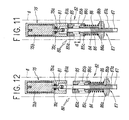
- the clutch piece 85 and the movement member 86 are together driven in a direction separating from the damper 75 (Figs. 11 and 12).
- the spirally operating mechanism 87 disposed between the movement member 86 and the fixed shaft 67 moves the movement member 86 relative to the fixed shaft 67 in a direction separating from the damper 75 during unwinding after the start of unwinding the screen 7, and after the movement member 86 is moved by a distance d shown in Fig. 11, the mechanism 87 engages with the clutch piece 85 so as to also move the clutch piece 85 in the same direction. Therefore, during winding the screen 7, when the clutch piece 85 is not separated from the clutch piece 81 (Figs. 10 and 11), upon starting to wind the screen 7, the clutch pieces 81 and 85 are simultaneously connected together so as to operate the damper 75. On the other hand, when both the clutch pieces 81 and 85 are separated from each other (Fig.
- the movement member 86 is moved toward the damper 75 by the winding of the screen 7 together with the clutch piece 85, and after the clutch piece 85 abuts the clutch piece 81, the damper 75 is operated until the completion of winding of the screen 7, i.e., during screwing of the movement member 86 by the distance d.
- the damper 75 includes a braking cylinder 75b rotatably accommodated within the clutch piece 81 constituting the casing with viscous fluid therebetween and a rotation shaft 75a extending from one end of the braking cylinder 75b so as to be derived from the casing with a sealing member 75c therebetween.
- the end of the rotation shaft 75a is connected to one end of the fixed shaft 67.
- the structure is not limited to this, and known various structures may be adopted.
- the one-way clutch mechanism 80 is provided, which connects between the damper 75 and the winding shaft 6 during winding the screen 7; during unwinding the screen 7, as shown in Figs. 9 to 12, the rotation of the winding shaft 6 is not transmitted to the damper 75 by the one-way clutch mechanism 80, so that a resistance force due to friction within the damper 75 is not applied thereto during unwinding the screen 7 so as to reduce the resistance during unwinding the screen 7 as small as possible. Therefore, the screen can be unwound lightly further than in a conventional case where the one-way clutch mechanism is housed in the damper.
- the one-way clutch mechanism 80 becomes connected so as to connect the winding shaft 6 to the fixed shaft 67 via the damper 75 during several rotations just before the completion of housing the screen 7, so that although the winding shaft 6 is rotated by the rotational biassing force of the coil spring 9, increase in the rotation speed is suppressed by the buffer power of the damper 75, preventing large impact and large collision noise from being produced when the operation frame 8 collides with the winding box.
- Figs. 13 and 14 show a fourth embodiment according to the present invention.
- An automatic winding screen device integrally includes the coil spring 9 as a power source for winding the screen 7 and the fixed shaft 66 in that an end of part of the one-way clutch mechanism is fixed to the bracket 12 disposed at the upper end of the winding box.
- both ends of the winding shaft 6 are rotatably supported to the brackets 12 and 13 of the winding box via the support members 64 and 65, respectively, and the fixed shaft 66 fixed to the upper bracket 12 at an end is inserted into the inside of the winding shaft 6.
- one end of the coil spring 9 is wound around and fixed to the spring support seat 68 while the other end of the coil spring 9 is rotatably attached to the fixed shaft 66, and the rotatable spring support seat 69 is fixedly fixed to the winding shaft 6. Therefore, the winding shaft 6 of the screen 7 is connected to the fixed shaft 66 via the coil spring 9.
- the fixed shaft 66 can be fixed to the bracket of the winding box in an arbitrarily rotating state using known means provided for adjusting the rotational biassing force of the coil spring 9.
- the damper 75 is provided, and between the rotation shaft 75a of the damper 75 and the winding shaft 6, the one-way clutch mechanism 80 is provided.
- the one-way clutch mechanism 80 includes the damper-side clutch piece 81 arranged on the fixed shaft 67, which is fixed to the winding box, with the oil damper 75 therebetween and the winding shaft-side clutch piece 85 rotating together with the winding shaft 6 and also being slidable along the axial direction of the winding shaft 6.
- the mechanism 80 also includes the clutch spring 84 for urging both the clutch pieces 81 and 85 in a direction mating each other and the clutch member 82 constituting the clutch time-difference operating means for maintaining the connection of both the clutch pieces 81 and 85 while the winding shaft 6 rotates by a predetermined number of rotations from a full wound state when the screen 7 is opened, and then for separating both the clutch pieces 81 and 85 apart against an urging force of the clutch spring 84.
- the fixed shaft 66 is appropriately rotated so that the movement member 86 is changed in position on a male screw 66a on the fixed shaft 66.
- the movement member 86 in the clutch piece 82 exceeds the operational range of the spirally operating mechanism 87, i.e., when a female screw 86b of the movement member 86 screwed to the male screw 66a engraved in the fixed shaft 66 exceeds the range of the male screw 66a, there is provided an idling region 66b at the end of a threading range of the male screw 66a on the fixed shaft 66 for idling the movement member 86 therein relative to the fixed shaft 66.
- the threading range of the male screw 66a is required to be within a range that the female screw 86b of the movement member 86 moves from the complete unwound state to starting to operate the damper 75 by the mutual connection of the pair of clutch pieces 81 and 85 by the way during the winding of the screen 7 around the winding shaft 6.
- the length difference is absorbed in the idling region 66b.
- a spring 89 is provided between a spring seat 88 disposed on the fixed shaft 66 and the movement member 86.
- the spring 89 may be sufficient to push the female screw 86b of the movement member 86 towards the male screw 66a of the fixed shaft 66 to an extent capable of mating them together when the winding shaft 6 is rotated in a direction winding the screen 7.
- the spring 89 may also be omitted as the urging means.
- Figs. 15 to 17 show a fifth embodiment according to the present invention.
- An automatic winding screen device includes a damper-side clutch piece 91 and a winding shaft-side clutch piece 95 having a female screw 95b engraved on the internal periphery, the winding shaft-side clutch piece 95 rotating integrally with the winding shaft 6 and also being slidable along the axial direction of the winding shaft 6, as a one-way clutch mechanism 90.
- the screen device also includes a clutch member 92 constituting clutch time-difference operating means having a screw 96a mated to the female screw 95b on the external periphery and a movement member 96 slidable in the axial direction of the fixed shaft 67 and a clutch spring 94 for urging the movement member 96 to the damper.
- the clutch member 92 includes the winding shaft-side clutch piece 95 having the female screw 95b engraved on the internal periphery and the movement member 96 movable relative to the clutch piece 95 in the axial direction of the fixed shaft 67, and wherein a spirally operating mechanism 97 is constructed by mating the male screw 96a formed on the external periphery of the movement member 96 with the female screw 95b formed on the internal periphery of the winding shaft-side clutch piece 95.
- a spirally operating mechanism 97 is constructed by mating the male screw 96a formed on the external periphery of the movement member 96 with the female screw 95b formed on the internal periphery of the winding shaft-side clutch piece 95.
- the movement member 96 is movable relative to the clutch piece 95 in the axial direction of the fixed shaft 67, and both ends of a pin 67b penetrated into the fixed shaft 67 in a direction perpendicular to the axial direction are inserted into grooves 96c and 96c formed on the internal periphery so as to oppose each other, so that the movement member 96 is inserted and fitted into the clutch piece 95 so as to be slidable in the axial direction but in a state where rotation is restricted by the fixed shaft 67.
- a clutch spring 94 is provided between an end of the winding shaft 6 in the movement member 96 adjacent to the support member 95 and the spring support seat 68 disposed on the fixed shaft 67.
- the clutch spring 94 may be sufficient to always mate the clutch piece 95 with the clutch piece 91 by pushing even when the screen device is arranged upside down.
- the spirally operating mechanism 97 disposed between the movement member 96 and the fixed shaft 67 moves the movement member 96 and the clutch piece 95 relative to the fixed shaft 67 from the state shown in Fig. 15 to the state shown in Figs. 16 and 17 during unwinding after the start of unwinding the screen 7.
- the clutch piece 95 is moved in a direction separating from the clutch piece 91, while when during winding the screen 7, the clutch piece 95 is inversely operated. Therefore, during winding the screen 7, when the clutch piece 95 is not separated from the clutch piece 91 (Figs. 15 and 16), upon starting to wind the screen 7, the clutch pieces 91 and 95 are simultaneously connected together so as to operate the damper 75.
- a fixed shaft (see Figs. 8 and 14) of a winding spring disposed in the bracket of the winding box may be connected if required.
- the fixed shaft is connected, to the same effect as that of the second embodiment, it is necessary that an idling region without a thread is provided on the male screw 96a of the movement member 96 for idling the clutch piece 95 therein while the rotational biassing force of the coil spring can be adjusted by the rotation of the fixed shaft around the bracket of the winding box.
Landscapes
- Engineering & Computer Science (AREA)
- Structural Engineering (AREA)
- Life Sciences & Earth Sciences (AREA)
- Insects & Arthropods (AREA)
- Pest Control & Pesticides (AREA)
- Architecture (AREA)
- Civil Engineering (AREA)
- Operating, Guiding And Securing Of Roll- Type Closing Members (AREA)
Applications Claiming Priority (5)
| Application Number | Priority Date | Filing Date | Title |
|---|---|---|---|
| JP2002294104 | 2002-10-07 | ||
| JP2002294104A JP4073286B2 (ja) | 2002-10-07 | 2002-10-07 | 自動巻取り式スクリーン装置 |
| JP2003147915 | 2003-05-26 | ||
| JP2003147915A JP3990317B2 (ja) | 2003-05-26 | 2003-05-26 | 自動巻取り式スクリーン装置 |
| PCT/JP2003/012822 WO2004031525A1 (fr) | 2002-10-07 | 2003-10-07 | Dispositif ecran a enroulement automatique |
Publications (3)
| Publication Number | Publication Date |
|---|---|
| EP1550787A1 true EP1550787A1 (fr) | 2005-07-06 |
| EP1550787A4 EP1550787A4 (fr) | 2006-01-04 |
| EP1550787B1 EP1550787B1 (fr) | 2011-07-13 |
Family
ID=32072505
Family Applications (1)
| Application Number | Title | Priority Date | Filing Date |
|---|---|---|---|
| EP03751357A Expired - Lifetime EP1550787B1 (fr) | 2002-10-07 | 2003-10-07 | Dispositif ecran a enroulement automatique |
Country Status (5)
| Country | Link |
|---|---|
| US (1) | US6938667B2 (fr) |
| EP (1) | EP1550787B1 (fr) |
| KR (1) | KR100635350B1 (fr) |
| CA (1) | CA2467472C (fr) |
| WO (1) | WO2004031525A1 (fr) |
Cited By (1)
| Publication number | Priority date | Publication date | Assignee | Title |
|---|---|---|---|---|
| EP3680446A4 (fr) * | 2017-09-06 | 2021-04-21 | TOK, Inc. | Dispositif de freinage pour un dispositif formant store du type à enroulement automatique |
Families Citing this family (40)
| Publication number | Priority date | Publication date | Assignee | Title |
|---|---|---|---|---|
| US7210513B2 (en) * | 2001-10-22 | 2007-05-01 | 420820 Ontario Limited | Screen frame with integral roll screen compartment and improvements thereof |
| WO2004051047A1 (fr) * | 2002-12-04 | 2004-06-17 | Jae-Suk Kwak | Grille a rouleaux destinee a un dispositif de reduction |
| TW200503651A (en) * | 2003-07-18 | 2005-02-01 | Fu-Mei Fun | Buffer device for roller blinds |
| JP4685002B2 (ja) * | 2004-06-14 | 2011-05-18 | セイキ住工株式会社 | 横引きロール網戸 |
| US20060162878A1 (en) * | 2005-01-27 | 2006-07-27 | Paul Lin | Window blind with a resistance-providing unit |
| US7461683B2 (en) * | 2005-02-28 | 2008-12-09 | Wen-Jen Wang | Curtain rolling buffer apparatus |
| DE102005014173B4 (de) * | 2005-03-29 | 2010-11-11 | Webasto Ag | Rolloanordnung, insbesondere Laderaumabdeckung für den Laderaum eines Fahrzeugs, mit Endlagendämpfung |
| KR100701860B1 (ko) * | 2005-04-18 | 2007-03-30 | 박영호 | 방충망의 승하강 속도조절이 자유로운 방충망장치 |
| ITMI20050198U1 (it) * | 2005-05-25 | 2006-11-26 | Salvatore Lupo | Dispositivo di controllo della velocita' di apertura o chiusura di una zanzariera o somile |
| AU2006257667A1 (en) * | 2005-06-16 | 2006-12-21 | Screenline Innovations Inc. | Retractable screen door housing handle balancing system |
| KR100669485B1 (ko) * | 2005-07-22 | 2007-01-16 | 곽명숙 | 롤블라인드 |
| CA2621180A1 (fr) * | 2005-09-01 | 2007-03-08 | Megair Ltd. | Procede et appareil de traitement d'air biologiquement contamine |
| KR20100084604A (ko) * | 2007-10-24 | 2010-07-27 | 쮸 시아오잉 | 감아올림 스크린 장치 |
| KR100909039B1 (ko) * | 2009-03-23 | 2009-07-22 | 이명숙 | 롤 회전방식 방충망의 감속장치 |
| CN101608530B (zh) | 2009-07-16 | 2012-01-25 | 李七妹 | 一种卷帘用的卷筒驱动装置的改进结构 |
| JP5284238B2 (ja) * | 2009-10-07 | 2013-09-11 | 株式会社メタコ | スクリーン装置 |
| JP5284239B2 (ja) * | 2009-10-07 | 2013-09-11 | 株式会社メタコ | スクリーン装置 |
| IT1400360B1 (it) * | 2010-06-01 | 2013-05-31 | Mv Line Srl Ora Mv Line Spa | Zanzariera avvolgibile a scorrimento orizzontale per porte e finestre |
| CN101949256B (zh) * | 2010-08-11 | 2012-07-25 | 杨再德 | 一种铝合金内开内倒窗的内置式隐形纱窗盒 |
| JP5776304B2 (ja) * | 2011-04-22 | 2015-09-09 | アイシン精機株式会社 | 車両用シート巻取り装置 |
| CN102213070B (zh) | 2011-05-13 | 2012-10-17 | 李七妹 | 一种窗帘用珠链式拉绳机构 |
| CN102251741B (zh) | 2011-05-13 | 2012-10-17 | 李七妹 | 一种窗帘用双方向可调驱动的拉绳机构 |
| US9480241B2 (en) | 2011-07-05 | 2016-11-01 | Eric James Holmstrom | Retractable leash system |
| CN102767329B (zh) | 2012-07-23 | 2014-07-16 | 李七妹 | 一种窗帘用单拉绳驱动装置 |
| CA2900078C (fr) | 2013-02-28 | 2021-07-06 | Odl, Incorporated | Porte escamotable a panneaux flexibles |
| EP3013189B8 (fr) * | 2013-06-28 | 2018-06-27 | Screenaway Pty Ltd | Fenêtre ou porte avec un écran roulant |
| CN103507604B (zh) * | 2013-10-24 | 2015-12-09 | 昆山誉球模塑有限公司 | 车辆天窗遮阳帘组件及车辆 |
| DE202014004349U1 (de) * | 2014-05-23 | 2015-08-26 | M.A.C.'s Holding Gmbh | Schutzrollo für eine Fenster- oder Türöffnung |
| CA2987009A1 (fr) | 2014-07-14 | 2016-01-21 | Tachikawa Corporation | Dispositif de blindage |
| US9848583B2 (en) * | 2015-07-02 | 2017-12-26 | Ellis Junior Smith | Retractable leash |
| US9593530B1 (en) * | 2015-08-18 | 2017-03-14 | Hunter Douglas Inc. | Brake assembly for a covering for an architectural opening |
| CN205605050U (zh) * | 2016-01-22 | 2016-09-28 | 亿丰综合工业股份有限公司 | 窗帘的阻尼装置 |
| CN205532187U (zh) * | 2016-01-29 | 2016-08-31 | 亿丰综合工业股份有限公司 | 窗帘升降控制结构 |
| KR101674430B1 (ko) * | 2016-03-22 | 2016-11-10 | 우일산업 주식회사 | 감속 브레이크 장치 및 이를 포함하는 수문 권양기 |
| KR101908189B1 (ko) * | 2016-08-09 | 2018-10-16 | 우일산업 주식회사 | 감속 브레이크 장치 및 이를 포함하는 수문 권양기 |
| KR101717047B1 (ko) * | 2016-12-26 | 2017-03-27 | 곽재석 | 롤 블라인드의 스프링 장력 사전 구속장치 |
| US11078996B2 (en) | 2017-09-14 | 2021-08-03 | Nidec Copal Corporation | Drive device and electronic device |
| KR101877691B1 (ko) * | 2017-11-17 | 2018-07-11 | 최승영 | 접이식문 창틀의 내문편을 자동 접힘 및 펼침 유도가동부 |
| IT201800000787A1 (it) * | 2018-01-12 | 2019-07-12 | Dieffepiu S R L | Tenda con telo avvolgibile |
| US11643864B2 (en) | 2018-01-23 | 2023-05-09 | Pella Corporation | Screen edge retention and screen rethreading features for a hidden screen assembly and a fenestration assembly |
Citations (2)
| Publication number | Priority date | Publication date | Assignee | Title |
|---|---|---|---|---|
| EP0919854A1 (fr) * | 1997-11-27 | 1999-06-02 | Kabushiki Kaisha Nichibei | Ecran à rouleau |
| EP0922831A2 (fr) * | 1997-12-12 | 1999-06-16 | Hunter Douglas Industries B.V. | Dispositif d'enroulement |
Family Cites Families (14)
| Publication number | Priority date | Publication date | Assignee | Title |
|---|---|---|---|---|
| US471467A (en) * | 1892-03-22 | Friction-roller | ||
| US4466475A (en) * | 1981-11-16 | 1984-08-21 | Kabushiki Kaisha Nichibei | Device for driving and stopping a roll blind |
| JPS58165188U (ja) * | 1982-04-30 | 1983-11-02 | ト−ソ−株式会社 | ロ−ルブラインドの減速装置 |
| US4662423A (en) * | 1982-10-31 | 1987-05-05 | Kabushiki Kaisha Nichibei | Device for operating roll-screen |
| JPS59118982A (ja) * | 1982-12-24 | 1984-07-09 | メタコ企業株式会社 | ロ−ルスクリ−ンの巻取り制動装置 |
| IT208635Z2 (it) * | 1986-12-17 | 1988-05-28 | Mottura Spa | Tenda a rullo con freno a masse centrifughe disposto all esterno del rullo e sopporto d estremita includente tale freno |
| JPH06212867A (ja) * | 1992-11-30 | 1994-08-02 | Toso Co Ltd | コード操作可能なロールブラインド |
| DE4436237C1 (de) * | 1994-10-11 | 1995-12-14 | Gkn Viscodrive Gmbh | Antriebsvorrichtung für vertikal bewegbare Tore |
| JPH10306667A (ja) * | 1997-05-08 | 1998-11-17 | Ykk Architect Prod Kk | 網 戸 |
| JPH10306668A (ja) | 1997-05-08 | 1998-11-17 | Hokuyuu:Kk | スライド網戸用ばね調整摘み装置 |
| JP3320658B2 (ja) * | 1998-07-10 | 2002-09-03 | 立川ブラインド工業株式会社 | ロールブラインドの昇降装置 |
| JP3457214B2 (ja) * | 1999-05-27 | 2003-10-14 | 立川ブラインド工業株式会社 | ロールブラインドの昇降装置 |
| US6591890B1 (en) * | 2001-07-19 | 2003-07-15 | Clear View Products, Inc. | Speed reducer for retractable screen systems |
| US6629555B2 (en) * | 2001-10-25 | 2003-10-07 | Odl, Incorporated | Retractable screen door |
-
2003
- 2003-10-07 US US10/494,034 patent/US6938667B2/en not_active Expired - Lifetime
- 2003-10-07 KR KR1020047007832A patent/KR100635350B1/ko not_active IP Right Cessation
- 2003-10-07 WO PCT/JP2003/012822 patent/WO2004031525A1/fr active Application Filing
- 2003-10-07 CA CA2467472A patent/CA2467472C/fr not_active Expired - Lifetime
- 2003-10-07 EP EP03751357A patent/EP1550787B1/fr not_active Expired - Lifetime
Patent Citations (2)
| Publication number | Priority date | Publication date | Assignee | Title |
|---|---|---|---|---|
| EP0919854A1 (fr) * | 1997-11-27 | 1999-06-02 | Kabushiki Kaisha Nichibei | Ecran à rouleau |
| EP0922831A2 (fr) * | 1997-12-12 | 1999-06-16 | Hunter Douglas Industries B.V. | Dispositif d'enroulement |
Non-Patent Citations (1)
| Title |
|---|
| See also references of WO2004031525A1 * |
Cited By (1)
| Publication number | Priority date | Publication date | Assignee | Title |
|---|---|---|---|---|
| EP3680446A4 (fr) * | 2017-09-06 | 2021-04-21 | TOK, Inc. | Dispositif de freinage pour un dispositif formant store du type à enroulement automatique |
Also Published As
| Publication number | Publication date |
|---|---|
| KR20040068151A (ko) | 2004-07-30 |
| CA2467472A1 (fr) | 2004-04-15 |
| KR100635350B1 (ko) | 2006-10-17 |
| EP1550787B1 (fr) | 2011-07-13 |
| WO2004031525A1 (fr) | 2004-04-15 |
| EP1550787A4 (fr) | 2006-01-04 |
| CA2467472C (fr) | 2011-04-26 |
| US6938667B2 (en) | 2005-09-06 |
| US20040261958A1 (en) | 2004-12-30 |
Similar Documents
| Publication | Publication Date | Title |
|---|---|---|
| EP1550787A1 (fr) | Dispositif ecran a enroulement automatique | |
| US7487816B2 (en) | Take up-type screen device | |
| WO2019149238A1 (fr) | Charnière de terminal mobile avec écran flexible pliable vers l'intérieur, et terminal mobile avec écran flexible pliable vers l'intérieur | |
| US20020113158A1 (en) | Apparatus for winding sheet-like element | |
| TW200300478A (en) | Recoil starter | |
| CN101235697B (zh) | 车辆用自动开闭装置 | |
| JP6636780B2 (ja) | 開閉部材駆動装置および開閉部材駆動装置ユニット | |
| JP4073286B2 (ja) | 自動巻取り式スクリーン装置 | |
| US6932205B2 (en) | Clutch | |
| JP3990317B2 (ja) | 自動巻取り式スクリーン装置 | |
| JP6629472B1 (ja) | 窓開閉装置 | |
| JP2003212089A (ja) | ウエビング巻取装置 | |
| JP2002310132A (ja) | ヒンジ用ロータリーアクチュエータ | |
| TW200419062A (en) | An automatic wind-up screen device | |
| JP2002295153A (ja) | シャッターの駆動装置 | |
| JPH035669Y2 (fr) | ||
| JP3912081B2 (ja) | 便座・便蓋閉止装置 | |
| JPS59130983A (ja) | ドア閉鎖機構 | |
| JPH0544469Y2 (fr) | ||
| JP2589525Y2 (ja) | 電動式シャッターの巻取り装置 | |
| JPH07180457A (ja) | 巻取軸 | |
| JPH10196211A (ja) | 両開き扉用ドアクローザー | |
| JPH042303Y2 (fr) | ||
| JPS6346837B2 (fr) | ||
| JP2568490Y2 (ja) | 電動シャッターの手動開放装置 |
Legal Events
| Date | Code | Title | Description |
|---|---|---|---|
| PUAI | Public reference made under article 153(3) epc to a published international application that has entered the european phase |
Free format text: ORIGINAL CODE: 0009012 |
|
| 17P | Request for examination filed |
Effective date: 20040712 |
|
| AK | Designated contracting states |
Kind code of ref document: A1 Designated state(s): BE DE ES FR GB GR IT LU NL |
|
| A4 | Supplementary search report drawn up and despatched |
Effective date: 20051123 |
|
| 17Q | First examination report despatched |
Effective date: 20081222 |
|
| GRAP | Despatch of communication of intention to grant a patent |
Free format text: ORIGINAL CODE: EPIDOSNIGR1 |
|
| GRAS | Grant fee paid |
Free format text: ORIGINAL CODE: EPIDOSNIGR3 |
|
| RIN1 | Information on inventor provided before grant (corrected) |
Inventor name: AOYAMA, TAKESHI,C/O SEIKI JUKO CO., LTD. Inventor name: SAWAGUCHI, NAOTO,C/O SEIKI JUKO CO., LTD. Inventor name: AOKI, TAKASHI,C/O SEIKI JUKO CO., LTD. Inventor name: SUGIYAMA, NOBORU,C/O SEIKI JUKO CO., LTD. |
|
| GRAA | (expected) grant |
Free format text: ORIGINAL CODE: 0009210 |
|
| RAP1 | Party data changed (applicant data changed or rights of an application transferred) |
Owner name: SEIKI JUKO CO., LTD. |
|
| AK | Designated contracting states |
Kind code of ref document: B1 Designated state(s): BE DE ES FR GB GR IT LU NL |
|
| REG | Reference to a national code |
Ref country code: GB Ref legal event code: FG4D |
|
| REG | Reference to a national code |
Ref country code: DE Ref legal event code: R096 Ref document number: 60337679 Country of ref document: DE Effective date: 20110901 |
|
| REG | Reference to a national code |
Ref country code: NL Ref legal event code: T3 |
|
| PG25 | Lapsed in a contracting state [announced via postgrant information from national office to epo] |
Ref country code: GR Free format text: LAPSE BECAUSE OF FAILURE TO SUBMIT A TRANSLATION OF THE DESCRIPTION OR TO PAY THE FEE WITHIN THE PRESCRIBED TIME-LIMIT Effective date: 20111014 |
|
| PLBE | No opposition filed within time limit |
Free format text: ORIGINAL CODE: 0009261 |
|
| STAA | Information on the status of an ep patent application or granted ep patent |
Free format text: STATUS: NO OPPOSITION FILED WITHIN TIME LIMIT |
|
| 26N | No opposition filed |
Effective date: 20120416 |
|
| GBPC | Gb: european patent ceased through non-payment of renewal fee |
Effective date: 20111013 |
|
| REG | Reference to a national code |
Ref country code: FR Ref legal event code: ST Effective date: 20120629 |
|
| REG | Reference to a national code |
Ref country code: DE Ref legal event code: R097 Ref document number: 60337679 Country of ref document: DE Effective date: 20120416 |
|
| PG25 | Lapsed in a contracting state [announced via postgrant information from national office to epo] |
Ref country code: GB Free format text: LAPSE BECAUSE OF NON-PAYMENT OF DUE FEES Effective date: 20111013 Ref country code: FR Free format text: LAPSE BECAUSE OF NON-PAYMENT OF DUE FEES Effective date: 20111102 |
|
| PG25 | Lapsed in a contracting state [announced via postgrant information from national office to epo] |
Ref country code: ES Free format text: LAPSE BECAUSE OF FAILURE TO SUBMIT A TRANSLATION OF THE DESCRIPTION OR TO PAY THE FEE WITHIN THE PRESCRIBED TIME-LIMIT Effective date: 20111024 |
|
| PG25 | Lapsed in a contracting state [announced via postgrant information from national office to epo] |
Ref country code: LU Free format text: LAPSE BECAUSE OF NON-PAYMENT OF DUE FEES Effective date: 20111007 |
|
| PGFP | Annual fee paid to national office [announced via postgrant information from national office to epo] |
Ref country code: BE Payment date: 20160913 Year of fee payment: 14 |
|
| PGFP | Annual fee paid to national office [announced via postgrant information from national office to epo] |
Ref country code: DE Payment date: 20161004 Year of fee payment: 14 |
|
| REG | Reference to a national code |
Ref country code: DE Ref legal event code: R119 Ref document number: 60337679 Country of ref document: DE |
|
| PG25 | Lapsed in a contracting state [announced via postgrant information from national office to epo] |
Ref country code: DE Free format text: LAPSE BECAUSE OF NON-PAYMENT OF DUE FEES Effective date: 20180501 |
|
| REG | Reference to a national code |
Ref country code: BE Ref legal event code: MM Effective date: 20171031 |
|
| PG25 | Lapsed in a contracting state [announced via postgrant information from national office to epo] |
Ref country code: BE Free format text: LAPSE BECAUSE OF NON-PAYMENT OF DUE FEES Effective date: 20171031 |
|
| PGFP | Annual fee paid to national office [announced via postgrant information from national office to epo] |
Ref country code: NL Payment date: 20220819 Year of fee payment: 20 |
|
| PGFP | Annual fee paid to national office [announced via postgrant information from national office to epo] |
Ref country code: IT Payment date: 20220913 Year of fee payment: 20 |
|
| REG | Reference to a national code |
Ref country code: NL Ref legal event code: MK Effective date: 20231006 |