EP1547894B1 - Track guided vehicle system - Google Patents
Track guided vehicle system Download PDFInfo
- Publication number
- EP1547894B1 EP1547894B1 EP04027684A EP04027684A EP1547894B1 EP 1547894 B1 EP1547894 B1 EP 1547894B1 EP 04027684 A EP04027684 A EP 04027684A EP 04027684 A EP04027684 A EP 04027684A EP 1547894 B1 EP1547894 B1 EP 1547894B1
- Authority
- EP
- European Patent Office
- Prior art keywords
- branching
- rollers
- guide
- track
- guided vehicle
- Prior art date
- Legal status (The legal status is an assumption and is not a legal conclusion. Google has not performed a legal analysis and makes no representation as to the accuracy of the status listed.)
- Expired - Fee Related
Links
Images


Classifications
-
- B—PERFORMING OPERATIONS; TRANSPORTING
- B61—RAILWAYS
- B61B—RAILWAY SYSTEMS; EQUIPMENT THEREFOR NOT OTHERWISE PROVIDED FOR
- B61B13/00—Other railway systems
- B61B13/04—Monorail systems
Definitions
- the present invention relates to a track guided vehicle system according to the preamble of claim 1.
- a track guided vehicle system uses track guided vehicles to transport articles in a clean room, in a general factory, hospital, or library, or outdoors. Branching is required to provided a complicated layout of running tracks.
- the Unexamined Japanese Patent Application Publication (Tokkai) No. 2003-212112 discloses branching control of a track guided vehicle system.
- a branching portion of the running track is provided with paired guide grooves for rectilinear progression and for branching.
- a track guided vehicle is provided with paired branching rollers corresponding to the guide grooves.
- the branching rollers can be extended to and withdrawn from a position where they are guided through the guide grooves and a position where they are free. Wether the track guided vehicle runs straight or shifts to a branch line is controlled by selecting the branching roller guided by the corresponding guide groove. Further, in the entire running track except for its branching portion, guide wheels are guided using a vertical portion of the running track.
- this track guided vehicle system requires the pair of guide grooves to be provided for the branching control. Consequently, the running track has a complicated shape.
- US-B1-6 308 636 defining the preamble of claim 1 discloses a track guided vehicle system where elevating and lowering of the switching rollers is effected by a pivoting motion to bring the switched rollers into and out of contact with the switching surface of a guide rail. It is therefore necessary to precisely control the actuators for the switched rollers to position at a predetermined height.
- claims 2 and 3 prevent elevation and lowering of the branching rollers from interfering with the guide rollers to eliminate the need to reduce speed in front of a branching portion and to allow a track guided vehicle to run stably through the branching portion at high speed either for rectilinear progression or for branching.
- the cam follower When the cam plate is rotatively moved, the cam follower, for example, reciprocates in accordance with the spiral cam. This elevates or lowers the corresponding branching roller.
- the spiral cam is provided with the areas having the almost fixed radii of curvature from the center of rotative movement of the cam plate.
- the cam follower lies in one of these areas, the cam plate is stopped. Then, the height position of the branching roller measured when its elevation or lowering is stopped is almost fixed in spite of a small variation in the stopped position of the cam plate. Therefore, the height position of the branching roller can be precisely controlled.
- branching or rectilinear progression is selected by elevating or lowering the branching rollers in the area in the rectilinear progression section in which a gap is created between each branching roller and the corresponding guide track.
- the elevation and lowering of the branching rollers does not interfere with the guide tracks. This eliminates the need to decelerate the track guided vehicle in front of the branching portion. Consequently, the branching rollers can be smoothly elevated and lowered.
- the track guided vehicle is supported by pressing the right or left branching rollers and right or left guide rollers against the outer and inner surfaces of the corresponding guide track so as to create substantially no gaps. Accordingly, even where running wheels are separated from a floor or ground surface, the track guided vehicle is not shaken or impacted. Therefore, the track guided vehicle can run at high speed regardless of whether it runs straight through or shifts to a branch line in the branching portion.
- each of the guide tracks is wider in the branching portion so as to be tightly sandwiched between the corresponding branching rollers and guide rollers.
- each of the guide tracks is narrower in the rectilinear progression section so as to create a gap between the guide track and the corresponding branching rollers. In this manner, varying the width of the guide track enables each of the branching rollers to contact with the guide track or a gap to be created between them.
- 2 is an overhead traveling vehicle
- 4, 5 are front and rear paired bogies.
- 6 is an overhead traveling vehicle main body.
- the overhead traveling vehicle main body 6 is supported at the bottom of the bogies 4, 5 using a front and rear shafts 8, 8.
- a frame 10 is provided so as to connect the front and rear shafts 8, 8 together.
- a drive wheel 14 is driven via a running motor 12 on the frame 10. The drive wheel 14 is pressed by urging means (not shown in the drawing) against a bottom surface of an upper part of a running track to allow the overhead traveling vehicle 2 to run.
- Each of the front and rear bogies 4, 5 is provided with free running wheels 16, 18 and runs using a top surface of a lower part of the running track as a tread.
- a total of four guide rollers 20, 21 including the front and rear guide rollers, and the right and left guide rollers are provided at the top of each of the bogies 4, 5, and the guide rollers 20, 21 are guided using inner guide surfaces of a guide track.
- the guide rollers 21 are eccentric rollers and their structure is shown in Figure 3 .
- the guide rollers 20 are typical free rollers.
- paired branching rollers 22, 23 are provided near a central portion of each of the bogies 4, 5 and laterally outside the guide rollers 20, 21.
- the branching rollers 22, 23 are elevated and lowered using opposite phases.
- 30 is a pivoting arm and 32 is a pin acting as a pivoting center of the pivoting arm 30.
- an elevating and lowering member 34 is mounted at one end of the pivoting arm 30.
- the elevating and lowering member 34 elevates and lowers together with the branching rollers 22, 23.
- 36 is an elevating and lowering guide that guides elevating and lowering motion of the elevating and lowering member 34, and the elevating and lowering guide 36 is, for example, a linear guide.
- 35 is a slot formed in the elevating and lowering member 34 and through which a pin or the like provided at the tip of the pivoting arm 30 is slid with respect to the elevating and lowering member 34.
- a spiral cam groove 38 is formed around a rotative movement center 37 of each of the cam plates 24, 25, and a cam follower 40 provided at an end of the corresponding pivoting arm 30 is guided through the cam groove 38.
- the cams formed in the cam plates 24, 25 are not limited to groove-like ones but have only to be spiral so as to guide the cam followers. Further, the cam plates 24, 25 and the pivoting arms 30 are rotatively moved in a vertical plane to elevate and lower the branching rollers 22, 23.
- the cam groove 38 has, for example, three concentric areas having fixed radii of curvature from the rotative movement center 37.
- a low position area 42 has the smallest radius of curvature, and an intermediate position area 43 is located at a position obtained by rotatively moving the cam plates 24, 25 through, for example, 180 degrees.
- a high position area 44 is located at a position obtained by further rotatively moving the cam plates 24, 25 through, for example, 180 degrees.
- Each of the low position area 42 and high position area 44 is present within a rotation angle (phase) of 45 degrees in each of the cam plates 24, 25.
- the cam groove 38 is concentric and it is concentric within a phase of, for example, 90 degrees in the intermediate position area 43.
- the cam plates 24, 25 can be rotatively moved through a little more than 360 degrees.
- Detected portions 45, 46 are provided on each of the cam plates 24, 25 so as to project from the other portions in a radial direction.
- a phase sensor 48 detects the detected portions 45, 46, and the phase sensor 48 detects, for example, edges of the detected portions 45, 46. Each edge is located at an almost central portion of the concentric part of the area 42, 43, 44. That is, the phase sensor 48 uses the edges of the detected portions 45, 46 to detect when the cam follower 40 has reached almost the center of the area 42, 43, 44.
- the lateral paired cam plates 24, 25 are rotatively moved by the elevating and lowering motor 26, and are stopped by the brake 28.
- the layout of the cam groove 38 differs between the cam plates 24, 25 so that when one of the cam followers 40 is in the high position area 44 in the cam plate 24 side, the other cam follower 40 is in the low position area 42 in the cam plate 25 side.
- the intermediate position area 43 is set to have the same phase in the right and left cam plates 24, 25.
- a control section 49 controls the elevating and lowering motor 26, and the brake 28 in accordance with a signal from the phase sensor 48 to control the heights of the branching rollers 22, 23.
- a mechanism for elevating and lowering the branching rollers 22, 23 is arbitrary.
- Figure 3 shows an example of the guide roller 21.
- 21r is an eccentric roller consisting of a free roller.
- a shaft 21b of the eccentric roller 21r is eccentric to the axis of a mounting portion 21c. Rotating a threaded portion of the mounting portion 21c enables the distance between the lateral paired guide rollers to be adjusted at the site.
- the branching roller located closer to the eccentric rollers, for example, in this case, the branching roller 22 preferably has its lateral position freely adjusted as an eccentric roller.
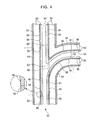
- 51 is a branching portion of the running track 50
- 52 is a rectilinear progression section (this means that this section has no branch or mergence).
- a right and left treads 53, 53 are provided on a top surface of a lower part of the box-like running track 50 to support running wheels 16, 18.
- an opening 54 is formed between the treads 53, 53 so that the shafts 8, used to connect the bogies 4, 5 together, can pass through the opening 54.
- guide track 56 projecting downward in the vertical direction are provided on the right and left sides, respectively, of a bottom surface of an upper part of the running track 50. The width of the guide track 56 is set to vary between the rectilinear progression section 52 and the branching portion 51.
- the guide track 56 in the branching portion 51 is formed as a wider portion 58 that is wider than the guide track 56 in the rectilinear progression section 52 by, for example, about 1 mm outward in the lateral direction (wider on the side of the guide track 56 with which the branching rollers 22, 23 contact).
- a gap of, for example, about 1 mm is created between the guide track 56 and the branching rollers 22, 23.
- each eccentric guide roller 21 is used to adjust the spacing between the guide rollers 20, 21 at the time of installation or the like, the guide rollers 20, 21 are in tight contact with inner surfaces of the guide tracks 56, 56.
- running upward in Figure 4 corresponds to rectilinear progression
- running upward and rightward in Figure 4 corresponds to branching.
- the guide track 56 and its wider portion 58 are arranged so as not to create any gap between them.
- the guide track 56 and its wider portion 58 are also arranged on the right side of the opening 54 except for a cut portion 64.
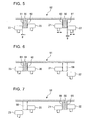
- Figure 5 shows how the guide rollers 20, 21 and the branching rollers 22, 23 are positioned relative to the guide track 56 in the rectilinear progression section 52.
- An inner surface of each of the guide tracks 56, 56 constitutes a guide surface 60
- an outer surface of the guide track 56 constitutes a guide surface 61.
- the guide surface 61 is shifted outward of the guide track 56 by about 1 mm.
- the branching rollers 22, 23 are at, for example, the height of the intermediate position.
- the left and right guide rollers 20, 21 contact tightly with the left and right guide surfaces 60, 60, respectively, to guide the overhead traveling vehicle 2.
- a solid line in Figure 8 shows how the running wheels 16 and others operate when the track guided vehicle passes through the Y-shaped portion 62.
- the running wheels 16 and others sink slightly to shake the bogies 4, 5.
- the wider portion 58 is tightly sandwiched between the rollers 20, 23 or the rollers 21, 22. This prevents the bogies 4, 5 from being shaken.
- Figures 9 and 10 show operations during rectilinear progression.
- the branching rollers 23 are at the high position, while the branching rollers 22 are at the low position.
- the right-hand branching rollers 22 do not contact with the guide track 56, while the wider portion 58 of the guide track 56 is sandwiched between the left-hand branching rollers 23 and the guide rollers 20.
- the branching rollers 22, 23 are elevated or lowered in a part of the rectilinear progression section 52 which lies in front of the branching portion 51. In this case, the elevation and lowering of the branching rotters 22, 23 does not interfere with the guide track 56. Therefore, the track guided vehicle can run straight through the branching portion 51 at high speed.
- Figures 11 and 12 show the conditions during branching.
- the branching rollers 22 are at the high position.
- the wider portion 58 is sandwiched between the branching rollers 22 and the guide rollers 21.
- the left-hand branching rollers 23 are at the low position and pass below the guide track 56.
- the branching rollers 22, 23 are elevated or lowered in a part of the rectilinear progression section 52 which lies in front of the branching portion 51. Therefore, the track guided vehicle can shift to the branch line at high speed.
- the guide track 56 is narrower than the wider portion 58 all along the rectilinear progression section 52.
- the guide track 56 may be formed to be narrower only in a predetermined area in front of the branching portion 51.
- the track guided vehicle may be run upward in Figure 4 .
- the branching rollers 22, 23 and others are operated as described in Figure 9 .
- the branching rollers 22, 23 and others are operated as described in Figure 11 .
- the branching rollers 22, 23 are switched between the three height positions.
- the branching rollers 22, 23 may be switched between two height positions for branching and rectilinear progression.
- the track guided vehicle may in principle run straight in the rectilinear progression section 52, and if the vehicle is to shift to a branch line, the branching rollers 22, 23 may be switched to the corresponding height position in front of the branching portion 51.
- the longitudinal paired guide rollers 20 and the longitudinal paired guide rollers 21 are provided on each bogie.
- Each branching roller is placed at the intermediate position of the bogie in its longitudinal direction.
- the longitudinal paired branching rollers may be provided on each bogie, with the guide rollers each provided at the intermediate position of the bogie in its longitudinal direction. In this case, the four branching rollers and the two guide rollers are provided on each bogie.
- the overhead traveling vehicle is shown in the embodiment.
- the present invention is applicable to a track guide vehicle that runs along a running track laid on the ground.
- an opening may be formed at the top of the running track, with a carriage placed over the opening.
- the guide tracks are provided on the bottom surface of the upper part of the running track and on the right and left sides, respectively, of the opening.
Landscapes
- Engineering & Computer Science (AREA)
- Transportation (AREA)
- Mechanical Engineering (AREA)
- Platform Screen Doors And Railroad Systems (AREA)
Applications Claiming Priority (6)
| Application Number | Priority Date | Filing Date | Title |
|---|---|---|---|
| JP2003432430 | 2003-12-26 | ||
| JP2003432430A JP4120877B2 (ja) | 2003-12-26 | 2003-12-26 | 有軌道台車システム |
| JP2004030011A JP4120878B2 (ja) | 2004-02-06 | 2004-02-06 | 有軌道台車 |
| JP2004030011 | 2004-02-06 | ||
| JP2004114424 | 2004-04-08 | ||
| JP2004114424A JP4120882B2 (ja) | 2004-04-08 | 2004-04-08 | 有軌道台車システム |
Publications (2)
| Publication Number | Publication Date |
|---|---|
| EP1547894A1 EP1547894A1 (en) | 2005-06-29 |
| EP1547894B1 true EP1547894B1 (en) | 2009-10-28 |
Family
ID=34557035
Family Applications (1)
| Application Number | Title | Priority Date | Filing Date |
|---|---|---|---|
| EP04027684A Expired - Fee Related EP1547894B1 (en) | 2003-12-26 | 2004-11-22 | Track guided vehicle system |
Country Status (5)
| Country | Link |
|---|---|
| US (1) | US7644664B2 (ko) |
| EP (1) | EP1547894B1 (ko) |
| KR (1) | KR100792612B1 (ko) |
| DE (1) | DE602004023810D1 (ko) |
| TW (1) | TWI291447B (ko) |
Cited By (1)
| Publication number | Priority date | Publication date | Assignee | Title |
|---|---|---|---|---|
| CN103842233A (zh) * | 2011-11-08 | 2014-06-04 | 株式会社Ihi | 台车以及台车搬运系统 |
Families Citing this family (31)
| Publication number | Priority date | Publication date | Assignee | Title |
|---|---|---|---|---|
| TWI291447B (en) | 2003-12-26 | 2007-12-21 | Murata Machinery Ltd | Track guided vehicle system |
| JP2006076699A (ja) * | 2004-09-08 | 2006-03-23 | Daifuku Co Ltd | 物品搬送車 |
| JP4264834B2 (ja) * | 2005-07-04 | 2009-05-20 | 村田機械株式会社 | 有軌道台車システム |
| JP5249509B2 (ja) * | 2006-11-10 | 2013-07-31 | 三菱重工業株式会社 | 軌道系交通システムの分岐装置 |
| US8069793B2 (en) * | 2008-05-21 | 2011-12-06 | Rice Vic G | Universally mountable model train |
| KR101032332B1 (ko) | 2009-02-09 | 2011-05-06 | 한국철도기술연구원 | 차상 제어 분기장치 및 분기방법 |
| JP5291507B2 (ja) * | 2009-03-25 | 2013-09-18 | 三菱重工業株式会社 | 軌道系車両用台車 |
| JP5145308B2 (ja) | 2009-10-14 | 2013-02-13 | 三菱重工業株式会社 | 案内軌条式車両の案内輪装置 |
| JP5357696B2 (ja) * | 2009-10-21 | 2013-12-04 | 三菱重工業株式会社 | 案内装置を有する軌条式車両 |
| KR101423183B1 (ko) * | 2010-06-18 | 2014-07-25 | 무라다기카이가부시끼가이샤 | 유궤도 대차 시스템 및 유궤도 대차 시스템에서의 분기 제어 방법 |
| JP5440870B2 (ja) * | 2010-08-19 | 2014-03-12 | 株式会社ダイフク | 物品搬送設備 |
| TWI473194B (zh) * | 2011-09-08 | 2015-02-11 | Inotera Memories Inc | 懸吊式晶圓傳輸系統 |
| JP5738165B2 (ja) * | 2011-12-19 | 2015-06-17 | 三菱重工業株式会社 | 交通システム |
| KR101407418B1 (ko) * | 2012-07-24 | 2014-06-18 | 주식회사 에스에프에이 | 반송 시스템 |
| KR101419359B1 (ko) * | 2013-04-08 | 2014-07-16 | 주식회사 에스에프에이 | 반송대차 및 이를 이용하는 반송시스템 |
| KR101436905B1 (ko) * | 2013-04-30 | 2014-11-04 | 주식회사 에스에프에이 | 반송대차 및 이를 이용하는 반송시스템 |
| KR101521498B1 (ko) * | 2013-05-31 | 2015-05-19 | 주식회사 에스에프에이 | 반송대차 및 이를 이용하는 반송시스템 |
| KR101479941B1 (ko) * | 2013-06-24 | 2015-01-13 | 주식회사 에스에프에이 | 반송대차 |
| KR101504146B1 (ko) * | 2013-07-24 | 2015-03-19 | 주식회사 에스에프에이 | 반송시스템 |
| JP6225803B2 (ja) * | 2014-04-07 | 2017-11-08 | 株式会社ダイフク | 物品搬送設備 |
| CN104555307B (zh) * | 2014-11-27 | 2017-03-29 | 南京熊猫电子股份有限公司 | 一种高空搬运系统 |
| JP6358142B2 (ja) * | 2015-03-26 | 2018-07-18 | 株式会社ダイフク | 物品搬送設備 |
| JP6304122B2 (ja) * | 2015-05-13 | 2018-04-04 | 株式会社ダイフク | 物品搬送設備 |
| US11155281B2 (en) * | 2016-12-29 | 2021-10-26 | Hyperloop Technologies, Inc. | Vehicle guidance system |
| CN109532859B (zh) * | 2017-09-22 | 2021-01-05 | 中车唐山机车车辆有限公司 | 一种微轨道岔结构及微轨轨道系统 |
| CN110723168B (zh) * | 2019-09-30 | 2023-08-18 | 江苏飞梭智行设备有限公司 | 一种平移变轨机构 |
| CN113745797B (zh) * | 2020-05-27 | 2024-01-05 | 比亚迪汽车工业有限公司 | 天线高度调节系统及车辆 |
| KR102597562B1 (ko) | 2021-08-09 | 2023-11-02 | (주)휴민텍 | Oht 반송차의 이중커브구간 운행방법 |
| KR20230040570A (ko) | 2021-09-16 | 2023-03-23 | (주)휴민텍 | Oht 반송차의 합류구간 운행 결정 방법 |
| WO2023156481A1 (de) * | 2022-02-17 | 2023-08-24 | Nt Innovation Ohg | Schienenfahrzeug, insbesondere zweiwegefahrzeug eingerichtet zum spurwechsel sowie entsprechendes system und verfahren |
| US11459706B1 (en) * | 2022-03-15 | 2022-10-04 | Robert Mosby | Rapid transit system with wheel in track design |
Family Cites Families (21)
| Publication number | Priority date | Publication date | Assignee | Title |
|---|---|---|---|---|
| JPS5026818Y2 (ko) | 1971-05-31 | 1975-08-11 | ||
| US4132175A (en) | 1977-02-23 | 1979-01-02 | Westinghouse Electric Corp. | Switching apparatus for mass transit vehicle |
| DE2743077A1 (de) * | 1977-09-24 | 1979-04-05 | Daimler Benz Ag | Selbsttaetig quergefuehrtes fahrzeug, insbesondere fuer den oeffentlichen personennahverkehr |
| US4671185A (en) * | 1983-01-10 | 1987-06-09 | Regents Of The University Of Minnesota | Switch mechanism |
| JPH0687436A (ja) | 1992-09-04 | 1994-03-29 | Murata Mach Ltd | 物品搬送装置 |
| US5277124A (en) * | 1992-10-28 | 1994-01-11 | Bae Automated Systems, Inc. | Direction control assembly for a material handling car having pivoted divert aims engaging tracks for guidance in switch area |
| JP3357167B2 (ja) | 1993-05-26 | 2002-12-16 | 松下電工株式会社 | 繊維強化プラスチックの製造方法 |
| JPH07229362A (ja) | 1994-02-21 | 1995-08-29 | Nippon Cable Syst Inc | 窓の開閉装置およびそれを用いた窓の一斉開閉装置 |
| JPH09221023A (ja) | 1996-02-17 | 1997-08-26 | Daifuku Co Ltd | 搬送用電車の走行ガイド装置 |
| DE19725644A1 (de) * | 1997-06-18 | 1998-12-24 | Alsthom Cge Alcatel | Bahn für mittels Weichen verzweigte Schienenstränge |
| JPH11222122A (ja) * | 1998-02-03 | 1999-08-17 | Shinko Electric Co Ltd | 分岐軌道を備えた搬送設備 |
| JP3506324B2 (ja) | 1999-09-06 | 2004-03-15 | 川崎重工業株式会社 | 舵取り装置付の台車を用いた搬送設備 |
| US6308636B1 (en) * | 1999-11-11 | 2001-10-30 | Raytheon Company | In-vehicle switch mechanism |
| JP4240708B2 (ja) | 1999-12-17 | 2009-03-18 | 株式会社ダイフク | 搬送設備 |
| US6629502B2 (en) * | 2000-09-14 | 2003-10-07 | Daifuku Co., Ltd. | Conveyance system |
| JP4483055B2 (ja) | 2000-09-14 | 2010-06-16 | 株式会社ダイフク | 搬送設備 |
| JP3411268B2 (ja) | 2000-11-24 | 2003-05-26 | 川崎重工業株式会社 | 搬送台車式搬送システム |
| JP4125508B2 (ja) | 2001-11-13 | 2008-07-30 | 新潟トランシス株式会社 | 案内軌条式車両用台車の案内輪支持装置 |
| JP4122781B2 (ja) | 2002-01-25 | 2008-07-23 | 村田機械株式会社 | 無人搬送車 |
| TWI291447B (en) | 2003-12-26 | 2007-12-21 | Murata Machinery Ltd | Track guided vehicle system |
| JP4120877B2 (ja) | 2003-12-26 | 2008-07-16 | 村田機械株式会社 | 有軌道台車システム |
-
2004
- 2004-08-17 TW TW093124685A patent/TWI291447B/zh not_active IP Right Cessation
- 2004-10-13 KR KR1020040081555A patent/KR100792612B1/ko active IP Right Grant
- 2004-11-17 US US10/989,412 patent/US7644664B2/en active Active
- 2004-11-22 DE DE602004023810T patent/DE602004023810D1/de active Active
- 2004-11-22 EP EP04027684A patent/EP1547894B1/en not_active Expired - Fee Related
Cited By (2)
| Publication number | Priority date | Publication date | Assignee | Title |
|---|---|---|---|---|
| CN103842233A (zh) * | 2011-11-08 | 2014-06-04 | 株式会社Ihi | 台车以及台车搬运系统 |
| CN103842233B (zh) * | 2011-11-08 | 2016-05-04 | 株式会社Ihi | 台车以及台车搬运系统 |
Also Published As
| Publication number | Publication date |
|---|---|
| KR20050066980A (ko) | 2005-06-30 |
| KR100792612B1 (ko) | 2008-01-09 |
| EP1547894A1 (en) | 2005-06-29 |
| US7644664B2 (en) | 2010-01-12 |
| TW200526507A (en) | 2005-08-16 |
| TWI291447B (en) | 2007-12-21 |
| US20050139114A1 (en) | 2005-06-30 |
| DE602004023810D1 (de) | 2009-12-10 |
Similar Documents
| Publication | Publication Date | Title |
|---|---|---|
| EP1547894B1 (en) | Track guided vehicle system | |
| KR101055167B1 (ko) | 궤도계 교통 시스템의 분기 장치 | |
| US7827917B1 (en) | Redundant steering system for guideway vehicle | |
| CN101238021A (zh) | 台车式运送装置 | |
| KR20060029692A (ko) | 곡선 모양의 조립 라인 및/또는 컨베이어 벨트 | |
| CN116031190B (zh) | 一种搬运系统 | |
| EP0237576B1 (en) | Shaft supporting mechanism for industrial robots | |
| US6220174B1 (en) | Guidance system with a truck guided on a rail | |
| EP0960848B1 (en) | Bridge crane | |
| KR20070047547A (ko) | 이송대차 시스템 | |
| CN113493162A (zh) | 悬吊式搬运设备及其导引装置与其方向保持模块 | |
| US6595347B2 (en) | Installation for the circulation of part-carrying pallets and a pallet for said installation | |
| JP4120882B2 (ja) | 有軌道台車システム | |
| JP4120878B2 (ja) | 有軌道台車 | |
| US6342768B1 (en) | Displacement apparatus arranged for guiding a carrying device along at least two rails | |
| JP2006249788A (ja) | 軌道用垂直分岐装置 | |
| JP2002103976A (ja) | スライドカバーを有する車両ルーフ | |
| JP4120877B2 (ja) | 有軌道台車システム | |
| KR20210156212A (ko) | 반송대차 및 반송대차 시스템 | |
| JP5362417B2 (ja) | パンタグラフ式リフタ | |
| JP3104782B2 (ja) | 保管設備 | |
| US20230322501A1 (en) | Transport robot and transport system | |
| CN217631926U (zh) | 一种站台门全长导向系统 | |
| CN118062462A (en) | Reversing adjusting mechanism and reversing adjusting method | |
| US11505216B2 (en) | Transfer cart |
Legal Events
| Date | Code | Title | Description |
|---|---|---|---|
| PUAI | Public reference made under article 153(3) epc to a published international application that has entered the european phase |
Free format text: ORIGINAL CODE: 0009012 |
|
| AK | Designated contracting states |
Kind code of ref document: A1 Designated state(s): AT BE BG CH CY CZ DE DK EE ES FI FR GB GR HU IE IS IT LI LU MC NL PL PT RO SE SI SK TR |
|
| AX | Request for extension of the european patent |
Extension state: AL HR LT LV MK YU |
|
| 17P | Request for examination filed |
Effective date: 20050905 |
|
| AKX | Designation fees paid |
Designated state(s): DE FR GB IT |
|
| 17Q | First examination report despatched |
Effective date: 20080211 |
|
| GRAP | Despatch of communication of intention to grant a patent |
Free format text: ORIGINAL CODE: EPIDOSNIGR1 |
|
| GRAS | Grant fee paid |
Free format text: ORIGINAL CODE: EPIDOSNIGR3 |
|
| GRAA | (expected) grant |
Free format text: ORIGINAL CODE: 0009210 |
|
| AK | Designated contracting states |
Kind code of ref document: B1 Designated state(s): DE FR GB IT |
|
| REG | Reference to a national code |
Ref country code: GB Ref legal event code: FG4D |
|
| REF | Corresponds to: |
Ref document number: 602004023810 Country of ref document: DE Date of ref document: 20091210 Kind code of ref document: P |
|
| PLBE | No opposition filed within time limit |
Free format text: ORIGINAL CODE: 0009261 |
|
| STAA | Information on the status of an ep patent application or granted ep patent |
Free format text: STATUS: NO OPPOSITION FILED WITHIN TIME LIMIT |
|
| GBPC | Gb: european patent ceased through non-payment of renewal fee |
Effective date: 20100128 |
|
| 26N | No opposition filed |
Effective date: 20100729 |
|
| PG25 | Lapsed in a contracting state [announced via postgrant information from national office to epo] |
Ref country code: GB Free format text: LAPSE BECAUSE OF NON-PAYMENT OF DUE FEES Effective date: 20100128 |
|
| PG25 | Lapsed in a contracting state [announced via postgrant information from national office to epo] |
Ref country code: IT Free format text: LAPSE BECAUSE OF FAILURE TO SUBMIT A TRANSLATION OF THE DESCRIPTION OR TO PAY THE FEE WITHIN THE PRESCRIBED TIME-LIMIT Effective date: 20091028 |
|
| REG | Reference to a national code |
Ref country code: FR Ref legal event code: ST Effective date: 20110331 |
|
| PG25 | Lapsed in a contracting state [announced via postgrant information from national office to epo] |
Ref country code: FR Free format text: LAPSE BECAUSE OF NON-PAYMENT OF DUE FEES Effective date: 20091228 |
|
| PGFP | Annual fee paid to national office [announced via postgrant information from national office to epo] |
Ref country code: DE Payment date: 20211118 Year of fee payment: 18 |
|
| REG | Reference to a national code |
Ref country code: DE Ref legal event code: R119 Ref document number: 602004023810 Country of ref document: DE |
|
| PG25 | Lapsed in a contracting state [announced via postgrant information from national office to epo] |
Ref country code: DE Free format text: LAPSE BECAUSE OF NON-PAYMENT OF DUE FEES Effective date: 20230601 |