EP1542093A2 - Bildlöschapparat und Bildlöschmethode - Google Patents
Bildlöschapparat und Bildlöschmethode Download PDFInfo
- Publication number
- EP1542093A2 EP1542093A2 EP04028858A EP04028858A EP1542093A2 EP 1542093 A2 EP1542093 A2 EP 1542093A2 EP 04028858 A EP04028858 A EP 04028858A EP 04028858 A EP04028858 A EP 04028858A EP 1542093 A2 EP1542093 A2 EP 1542093A2
- Authority
- EP
- European Patent Office
- Prior art keywords
- image
- heating
- medium
- erasing
- erasing apparatus
- Prior art date
- Legal status (The legal status is an assumption and is not a legal conclusion. Google has not performed a legal analysis and makes no representation as to the accuracy of the status listed.)
- Withdrawn
Links
Images



Classifications
-
- B—PERFORMING OPERATIONS; TRANSPORTING
- B41—PRINTING; LINING MACHINES; TYPEWRITERS; STAMPS
- B41M—PRINTING, DUPLICATING, MARKING, OR COPYING PROCESSES; COLOUR PRINTING
- B41M7/00—After-treatment of prints, e.g. heating, irradiating, setting of the ink, protection of the printed stock
- B41M7/0009—Obliterating the printed matter; Non-destructive removal of the ink pattern, e.g. for repetitive use of the support
-
- G—PHYSICS
- G03—PHOTOGRAPHY; CINEMATOGRAPHY; ANALOGOUS TECHNIQUES USING WAVES OTHER THAN OPTICAL WAVES; ELECTROGRAPHY; HOLOGRAPHY
- G03G—ELECTROGRAPHY; ELECTROPHOTOGRAPHY; MAGNETOGRAPHY
- G03G21/00—Arrangements not provided for by groups G03G13/00 - G03G19/00, e.g. cleaning, elimination of residual charge
-
- G—PHYSICS
- G03—PHOTOGRAPHY; CINEMATOGRAPHY; ANALOGOUS TECHNIQUES USING WAVES OTHER THAN OPTICAL WAVES; ELECTROGRAPHY; HOLOGRAPHY
- G03G—ELECTROGRAPHY; ELECTROPHOTOGRAPHY; MAGNETOGRAPHY
- G03G21/00—Arrangements not provided for by groups G03G13/00 - G03G19/00, e.g. cleaning, elimination of residual charge
- G03G21/0005—Arrangements not provided for by groups G03G13/00 - G03G19/00, e.g. cleaning, elimination of residual charge for removing solid developer or debris from the electrographic recording medium
-
- B—PERFORMING OPERATIONS; TRANSPORTING
- B41—PRINTING; LINING MACHINES; TYPEWRITERS; STAMPS
- B41J—TYPEWRITERS; SELECTIVE PRINTING MECHANISMS, i.e. MECHANISMS PRINTING OTHERWISE THAN FROM A FORME; CORRECTION OF TYPOGRAPHICAL ERRORS
- B41J2202/00—Embodiments of or processes related to ink-jet or thermal heads
- B41J2202/30—Embodiments of or processes related to thermal heads
- B41J2202/37—Writing and erasing thermal head
Definitions
- the present invention relates to an image-erasing apparatus for erasing an image formed, on a medium such as recording paper, with an erasable image-forming material and also relates to an image-erasing method of erasing an image formed, on the medium, with an erasable image-forming material.
- An erasable image-forming material is used to form, i.e., print, an image on a sheet of paper.
- the formed image is erased with an image-erasing apparatus so that the sheet of paper can be returned as a blank paper.
- the paper can be reused repeatedly, and therefore, the number of sheets of paper required can be substantially reduced.
- the quality of the paper is significantly degraded due to repeated reuse, the paper is recycled. In this way, the total cost of reuse of the paper can be reduced.
- an image-erasing apparatus is an apparatus for erasing an image formed on a recording medium (for example, a sheet of paper) with an image-forming apparatus such as a printer or a copying machine.
- the image-erasing apparatus includes a printing unit which uses toner or ink made of an erasable image-forming material and an erasing unit for removing the toner or the ink.
- Japanese Unexamined Patent Application Publication No. HEI 11-316527 discloses an image-erasing apparatus including a device for contacting a solvent to an erasable image-forming material which develops color on a sheet of paper, and a device for removing the solvent from the paper.
- the erasable image-forming material includes a color former, a developer, and a decolorizer.
- the solvent dissolves the developer and the decolorizer.
- Japanese Unexamined Patent Application Publication Nos. 2000-28450 and 2002-38039 disclose erasable image-forming materials.
- the images formed with the erasable materials are erased by a solvent or by the application of heat. These materials make it possible to reuse the paper.
- conventional image-erasing apparatuses require a solvent container for storing the solvent used for the erasing and a recovered-solvent container into which used solvent is recovered.
- a conventional image-erasing apparatus requires a carrying-in roller and a carrying-out roller for bringing the paper into contact with the solvent, a heat roller and an electronic cooler for controlling the temperature, and chemicals such as an adsorbent.
- a conventional image-erasing apparatus also requires a drive mechanism such as a circulation pump. Therefore, the overall structure of the image-erasing apparatus and the erasing process by using such apparatus are complex. In addition, it is necessary to carefully handle the used solvent for safety.
- an image-erasing apparatus using the solvent is not suitable for use in an office. Therefore, it is desired to realize an image-erasing apparatus suitable for office work of the structure that does not discharge or harmful substance or pollution such as exhaust gas, requires less installation location, is compact in size, and requires less power.
- a concrete erasing method using the image erasing apparatus for erasing the image formed on the medium such as recording paper there are provided, for example, a method of using a solvent and a method of utilizing heat, as briefly mentioned hereinbefore.
- treating or disposed method there are provided, for example, a mass treatment method in which papers printed with the erasable image-forming materials are collected from offices or working departments and simultaneously treated, and a dispersion (or separate) treatment method in which papers printed with the erasable image-forming materials are treated separately at portions near printers or copying machines utilized for the printing treatment.
- the erasing apparatus becomes large or big in size, which will require a specific room, chamber or building for treatment and in the case of the separate treatment method, a small-sized erasing apparatus is usable, being convenient in usual office work or treatment in office.
- the thermal erasing method using no organic solvent, may be suitable for the erasing apparatus of the image-forming material.
- the image-forming material erasing method or apparatus mentioned above provides the following undesirable matters.
- paper as a recording medium is also heated together with the printed image-forming material at the image erasing treatment time.
- Papers are usually classified into acid papers and neutral papers in accordance with their manufacturing methods.
- an ink bleeding-stop agent such as colophonium
- aluminium sulfate is generally utilized.
- the aluminium sulfate has a function of reacting to water to thereby generate acid and make the paper as acid paper.
- the paper using the aluminium sulfate is generally called “acid paper", in which cellulose as fiber of the paper is apt to be damaged, which provides a problem of durability of the paper.
- a paper utilizing a neutral material as sizing agent has been used to improve the durability of the paper, which is, on the other hand, called “neutral paper”.
- neutral paper in further consideration of preservation of the paper, such as calcium carbonate is added to neutralize acid in atmosphere to thereby keep weak alkaline property of the paper.
- the erasable image-forming material is erased by heating a medium such as recording paper on which the image is formed at a predetermined temperature.
- a medium such as recording paper on which the image is formed at a predetermined temperature.
- the components, such as those mentioned above, contained in the paper may be evaporated and an odor generating substance may be produced, such as, for example, benzaldehyde, octanol, or like.
- an odor generating substance will be dispersed at the erasing time in a room in which the erasing apparatus is set. This matter may also constitute an adverse problem if the room is not so wide.
- the present invention was conceived in consideration of the above matters encountered in the prior art mentioned above, and an object of the present invention is therefore to provide an image-erasing apparatus capable of effectively erasing an image formed, on a recording medium, with an erasable image-forming material with high safeness and being compact and suitable for use in an enclosed area such as an office.
- Another object of the present invention is to provide an image-erasing apparatus and method capable of preventing generation of odor substance which may be generated at the time of heating and erasing a recording medium such as image-forming material with low cost.
- an apparatus for erasing an image formed, on a medium, with an erasable image-forming material by heating the medium comprising:
- the heating unit may include: two heating plates between which the medium is disposed with being sandwiched from front and back surface sides thereof; and two heaters electrically connected to the power source and attached to the heating plates, respectively, for heating the two heating plates.
- the image-erasing apparatus may further include additional two heating plates and two heaters disposed on two side portions, opposing to each other, of the medium so as to surround the medium from four directions by the first mentioned two heating plates and heaters and the latter mentioned two heating plates and heaters, or the image-erasing apparatus may further include further additional two heating plates and two heaters disposed on two side portions, opposing to each other, other than two sides mentioned above, of the medium so as to surround the medium from six directions by the four heating plates and four heaters and the further mentioned two heating plates and two heaters.
- the image-erasing apparatus may further include two heat reflecting plates disposed on two side portions, opposing to each other, of the medium so as to surround the medium from four directions by the two heating plates and two heat reflecting plates, or the image-erasing apparatus may further include further additional two heat reflecting plates disposed on two side portions, opposing to each other, other than two sides mentioned above, of the medium so as to surround the medium from six directions by the two heating plates and the first mentioned two heat reflecting plates and the latter mentioned two heat reflecting plates.
- the image-erasing apparatus may further include a tray in which the medium is accommodated and which is heated by the heating unit.
- the apparatus may further include a fan disposed so as to blow an air to the heating unit to cool the same.
- the image-erasing apparatus may further include a heat-blocking plate operatively connected to a surface of the heating unit opposing to a surface thereof contacting to the heating unit on at least one of front and rear surface sides of the medium so as to reflect the heat from the heating unit.
- the heating unit may include two heating plates between which the medium is disposed with being sandwiched from front and back surface sides thereof and two heaters electrically connected to the power source and attached to the heating plates, respectively, for heating the two heating plates, and further comprising two heat-blocking plates disposed on outsides of both the heating units through a spacer on one side and an elastic member on the other side.
- the heating unit includes a single heating plate and a single heater attached to the heating plate, and further comprises three heat reflecting plates including one heat reflecting plate disposed so as to face the heating plate to thereby sandwich the medium therebetween and two heat reflecting plates disposed on both side surfaces of the medium so as to surround the medium from four directions by the one heating plate and three heat reflecting plates.
- the image-erasing apparatus of this embodiment may further include further additional two heat reflecting plates disposed on two side portions, opposing to each other, other than two sides mentioned above, of the medium so as to surround the medium from six directions by the one heating plates and the first mentioned two heat reflecting plates and the latter mentioned two heat reflecting plates.
- the image-erasing apparatus may further include an outer case in which the heating unit and a fan for cooling the heating unit are disposed, the case being provided with an air inlet through which air is introduced inside the case and an air outlet through which the air is discharged outside the case.
- a control unit may be disposed in the case and electrically connected to the heating unit and the fan for automatically controlling an operation of the heating unit and the fan, and an interlock mechanism may be further disposed in the case for interlocking the case.
- a handle may be attached to the case so as to carry the case.
- the image-erasing apparatus may further comprise a substance treating unit, disposed outside the case at a portion adjacent to the air outlet formed to the case for decomposing and then adsorbing a substance generated at a time of heating and erasing the image formed on the medium.
- a substance treating unit disposed outside the case at a portion adjacent to the air outlet formed to the case for decomposing and then adsorbing a substance generated at a time of heating and erasing the image formed on the medium.
- the substance treating unit may include a photo-catalyst carrier carrying a photo-catalyst, at least one pair of voltage terminals for applying voltage to the photo-catalyst carrier disposed between the paired voltage terminals, and a power source for supplying a power to the voltage terminals.
- An ozone treating device may be disposed for decomposing an ozone generated by the discharge between the paired terminals.
- the ozone treating device and the photo-catalyst carrier may be integrated as a unit.
- the substance treating unit and the heating unit may be synchronously operated.
- the substance decomposing unit may further include an adsorption device for adsorbing the substance generated at the time of heating and erasing the image formed on the medium.
- the substance treating unit may be disposed inside the case at a portion adjacent to the air outlet formed to the case for decomposing and then adsorbing a substance generated at a time of heating and erasing the image formed on the medium.
- the image-erasing method may further include the steps of preparing a substance treating unit including a photo-catalyst on a downstream side of the heating unit and decomposing, through a photo-catalyst reaction, an odor component contained in the substance and generated during the heating step.
- the image-erasing method may further include the step of adsorbing a substance generated in the heating step by a substance adsorption device disposed for the substance treating unit.
- a large installation space is not required, and no harmful substance is generated, thus being suitable for use in an enclosed area such as an office.
- An image-erasing apparatus 10 of this first embodiment is one usable alongside a printer or a copying machine in an office or like.
- This image-erasing apparatus 10 is comparatively compact, power-saving, and has high-efficiency.
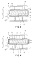
- a bundle of sheets of paper 1 is sandwiched between two heating plates 2 and 3. On each sheet of paper, an image is formed with an erasable image-forming material.
- the heating plates 2 and 3 are provided with plate-shaped electric heaters 4 and 5, respectively, which are electrically connected to a power source S.
- a heating unit is composed of the heating plates 2 and 3 and the electric heaters 4 and 5.
- the electric heater 4 is connected to a heat-blocking plate 8a via spacers 6.
- the electric heater 5 is connected to a heat-blocking plate 8b via an elastic member 7 such as spring(s) in this embodiment.
- a blower fan 9 functioning as a cooling device is provided. The blower fan 9 sends air to the heated portions so as to regulate the temperature.
- the heating plates 2 and 3 are made of metal, preferably, of a highly heat-conductive material such as aluminum or copper.
- the spacers 6 are preferably made of highly heat-insulating materials such as ceramics or FRP.
- the heat-blocking plates 8a and 8b are made of metal, and are preferably mirror-polished or mirror-coated. In consideration of office use, the heating plates 2 and 3 have a size suitable for A4 sheets of paper or a size suitable for A3 sheets of paper. Further, it may be preferred that the heating plates 2 and 3 have a size suitable for A3 size paper because the heating plates 2 and 3 also usable for A4 size paper.
- a bundle of sheets of paper 1 is placed between a pair of heating plates 2 and 3. While being urged by the elastic member 7, the heating plate 3 presses the paper bundle 1.
- the paper bundle 1 comes into contact with the heating plates 2 and 3 at its front and back surfaces. Heat conduction from the heating plates 2 and 3 to the paper bundle 1 is reliably maintained. Since the heating plates 2 and 3 are made of a highly heat-conductive material such as aluminum and copper, the surface temperature of the heating plates 2 and 3 is uniform, and therefore, the bundle of sheets of paper 1 can be heated uniformly, and as a result of this heat conduction, images formed on the sheets of paper are erased at a predetermined temperature.
- the heating plates 2 and 3 are made of a highly heat-conductive material, the surfaces of the heating plates 2 and 3 are evenly heated without requiring uniform arrangement of the electric heaters 4 and 5. Therefore, the selections or choices of the electric heaters 4 and 5 can be made widely.
- heat is radiated from the heating plates 2 and 3 and the electric heaters 4 and 5.
- the radiated heat is reflected by the heat-blocking plates 8a and 8b. Therefore, the heating efficiency is improved. If the heat-blocking plates 8a and 8b are mirror-polished or mirror-coated, the heating efficiency could be further improved.
- FIG. 2 shows an operating pattern of the image-erasing apparatus according to the first embodiment 1 of the present invention having the structure mentioned above.
- the temperature starts to increase.
- the temperature reaches the predetermined erasing temperature.
- the erasing temperature is maintained until a time T3.
- the cooling-down starts.
- the temperature returns to the room temperature.
- the erasable image-forming material develops color through an interaction between a color former and a developer included in the material.
- the color former preferentially dissolves with a binder resin in the material so that the material loses color.
- the decolorizer reacts with the developer so that the material loses color. The higher the temperature, the more quickly the reaction proceeds. However, if the temperature is too high, the paper burns and becomes discolored.
- the erasing temperature is preferably 120°C to 150°C.
- the image can be erased by maintaining the temperature in this range for a few hours. In the case where the erasing temperature is maintained in the range of 120°C to 150°C, the time required for the erasing is approximately an hour and a half to two hours.
- the power consumption required for the erasing is highest (P1) when the temperature increases. After the temperature reaches the erasing temperature and when the erasing temperature is maintained, the power consumption required is reduced to P2 because the power is used only to compensate the heat loss due to the heat radiation. In the cooling process, the power consumption required is further reduced to P3 because the power is used only for the operation of the blower fan 9. Therefore, the average power consumption required for erasing images is reduced. According to experiments conducted by the inventors, when the temperature increased for 30 minutes, and 500 sheets of A4 paper were processed, the maximum power consumption P1 ranged from 1 kW to 1.5 kW. Therefore, the image-erasing apparatus 10 can be used in an office having a 100V AC power supply.
- the heating plates 2 and 3 have a size suitable for A3 sheets of paper
- two bundles of A4 paper can be processed.
- the thickness of two paper bundles is half the thickness of a bundle in the case where the heating plates 2 and 3 have a size suitable for A4 sheets of paper. The smaller the distance between the heating plates 2 and 3, the more uniform the temperature of the space between the heating plates 2 and 3, thus further saving the power.
- the image-erasing apparatus 10 of this embodiment includes: the two heating plates 2 and 3 sandwiching a paper bundle 1 therebetween, the heating plates 2 and 3 having the size being suitable for A4 or A3; the electric heaters 4 and 5 serving as heating devices; the heat-blocking plates 8a and 8b for improving heating efficiency; and the blower fan 9 for shortening the cooling time, thereby realizing the apparatus 10 having compact size or dimension.
- the average power consumption of the apparatus 10 is low, and the maximum power consumption thereof is also low. Therefore, the apparatus 10 can be easily installed in an office.
- a bundle of sheets of paper 1 is contained in a metal tray 21 in a rested state thereon so that the metal tray 21 is disposed between the two heating plates 2 and 3.
- the metal tray 21 is preferably made of a highly heat-conductive material such as aluminum or copper.
- the paper bundle 1 is sandwiched between the two heating plates 2 and 3.
- the heating plates 2 and 3 are provided with the plate-shaped electric heaters 4 and 5, respectively, functioning as heating unit connected to the power source S.
- the electric heater 4 is connected to the heat-blocking plate 8a via spacers 6.
- the electric heater 5 is connected to the heat-blocking plate 8b via the elastic member 7 such as springs.
- the blower fan 9 functioning as a cooling device is provided. The blower fan 9 sends air to the heated portions so as to regulate the temperature.
- the paper bundle 1 is surrounded by the metal tray 21, and heat is conducted from the heating plate 3 to the metal tray 21. Since the metal tray 21 is made of a highly heat-conductive material, the temperature of the metal tray 21 becomes uniform of approximately the same temperature as that of the heating plate 3. Therefore, the top and bottom of the paper bundle 1 are heated by the heating plates 2 and 3, respectively. Furthermore, since the sides of the paper bundle 1 are heated by the side walls of the tray 21, the heating efficiency can be improved, and the power required for the heating is reduced. In addition, since the temperature of the paper bundle 1 is made uniform, the image-erasing characteristics can be improved.
- the bundle of sheets of paper 1 since the bundle of sheets of paper 1 is contained in the metal tray 21, the bundle of sheets of paper 1 can be simply and easily transferred to and from the image-erasing apparatus 20.
- a bundle of sheets of paper 1 is contained in a metal tray 21, which is disposed between the two heating plates 2 and 3, so that the average power consumption and the maximum power consumption can be reduced.
- it is simple to transfer the paper bundle 1 into and from the image-erasing apparatus 20.
- the image-erasing apparatus 30 according to the third embodiment 3 will now be described hereunder with reference to FIG. 4.
- the same reference numerals are added to the same components as those in the first and second embodiments and the description thereof is hence made short or omitted herein.
- a bundle of sheets of paper 1 is heated in a state of being surrounded on four sides by four heating plates 2, 3, 31 and 32.
- the heating plates 2, 3, 31 and 32 are provided with electric heaters 4, 5, 33 and 34, respectively, functioning as heating unit.
- the electric heater 4 is connected to the heat-blocking plate 8a via the spacers 6.
- the electric heater 5 is connected to the heat-blocking plate 8b via an elastic member 7 such as springs as shown.
- the blower fan 9 functioning as a cooling device is provided. The blower fan 9 sends air to the heated portions so as to regulate the temperature.
- a bundle of sheets of paper 1 is surrounded by the heating plates 31 and 32 in addition to the plates 2 and 3. Therefore, the heating characteristics and the uniformity of the heating temperature of the paper bundle 1 can be further improved.
- two side-surfaces of the bundle of sheets of paper 1 are provided with the heating plates 31 and 32, it may be possible to further arrange two heating plates so as to surround the four side-surfaces of the bundle of sheets of paper 1. In such arrangement, the paper bundle 1 is heated from six directions in total.
- a bundle of sheets of paper 1 is surrounded by the two heating plates 2 and 3 and two heat-reflecting plates 41 and 42.
- the heating plates 2 and 3 are provided with the electric heaters 4 and 5, respectively, functioning as heating unit.
- the electric heater 4 is connected to the heat-blocking plate 8a via the spacers 6.
- the electric heater 5 is connected to the heat-blocking plate 8b via the elastic member 7 such as springs.
- the blower fan 9 functioning as a cooling device is provided. The blower fan 9 sends air to the heated portions so as to regulate the temperature.
- the heat radiated from the heating plates 2 and 3 is reflected by the heat-reflecting plates 41 and 42. Therefore, the heating can be performed more efficiently and uniformly.
- the two heat-reflecting plates 41 and 42 are additionally provided on two sides of the paper bundle 1, it will be apparent that further two heat reflecting plates may be arranged so as to surround the paper bundle 1 from the four directions.
- the image-erasing apparatus 50 according to the fifth embodiment 5 will now be described hereunder with reference to FIG. 6.
- the same reference numerals are added to the same components as those in the former embodiments 1 to 4, and the description thereof is made short or omitted herein.
- a bundle of sheets of paper 1 is surrounded by a single heating plate 3 and heat-reflecting plates 41, 42, and 51. That is, the heating plate 2 in the former embodiments is removed.
- the heating plate 3 are provided with the electric heater 5 functioning as a heating unit.
- the electric heater 5 is connected to the heat-blocking plate 8b via the elastic member 7 such as springs as shown.
- the blower fan 9 functioning as a cooling device is provided. The blower fan 9 sends air to the heated portions so as to regulate the temperature.
- the heating unit is composed of only the single heating plate 3 and heater 5, production cost and weight of the entire apparatus can be reduced.
- further two reflecting plates may be arranged in addition to the vertical heat-reflecting plates 41 and 42 so as to surround the bundle of sheets of paper 1 from four sides thereof.
- the image-erasing apparatus 60 according to the sixth embodiment 6 will now be described hereunder with reference to FIG. 7.
- the same reference numerals are added to the same components as those in the former embodiments 1 to 5, and the description thereof is therefore made short or omitted herein.
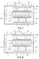
- the image-erasing apparatus 20 of the second embodiment 2 is contained in a case 60a which surrounds the structure of the second embodiment 2 of FIG. 3, for example.
- the bundle of sheets of paper 1 is sandwiched between the two heating plates 2 and 3.
- the heating plates 2 and 3 are provided with the electric heaters 4 and 5, respectively, functioning as heating unit.
- the electric heater 4 is connected to the heat-blocking plate 8a via the spacers 6.
- the electric heater 5 is connected to the heat-blocking plate 8b via the elastic member 7 such as springs as shown.
- the blower fan 9 functioning as a cooling device is provided. The blower fan 9 sends air to the heated portions so as to regulate the temperature.
- the case 60a is composed of an upper part (section) 61 and a lower part (section) 62 to be opened or detachable form each other, and the case 60a has a vent for the escape of heat.
- the vent may includes an air inlet 30a through which an external air is introduced into the case 60a by the operation of the fan 9 and an air outlet 30b through which the heated air is discharged outside the case 60a.
- such inlet and outlet 30a and 30b may be formed as slits.
- the case 60a is insulated with air from the heating plates 2 and 3 and the metal tray 21. It may be preferable to dispose an insulating member therebetween in order to reduce heat transfer to the case.
- a handle 63 may be provided for at least one of the upper part 61 and lower part 62 of the case 60a in order to improve portability and carry the case to another portion.
- the electric heaters 4 and 5 when the electric heaters 4 and 5 are heated at a high temperature, burn injury due to the touching of an operator to the heating plates 2 and 3 and the metal tray 21 can be prevented, thus improving the safety of the image-erasing apparatus 60.
- the entire structure of the apparatus in the case 60a may be supported therein in a suspended manner from an inner upper portion of the case 60a or may be fixed to the bottom thereof.
- the image-erasing apparatus 70 according to the seventh embodiment 7 will now be described hereunder with reference to FIG. 8.
- the same reference numerals are added to the same components as those in the former embodiments 1 to 6, particularly of the embodiment 6, and the description thereof is therefore made short or omitted herein.
- the image-erasing apparatus 70 of this seventh embodiment has a control unit 71, which is installed in the case 60a, for controlling the temperature and time required for heating the paper bundle 1 by the electric heating unit.
- the control unit 71 automatically controls the cooling start time and the time required for the cooling by blowing air.
- the control unit 71 has an interlocking mechanism for safety.
- control unit 71 is installed in addition to the apparatus 60 of FIG. 7, so that the safety of the image-erasing apparatus can be further improved.
- the erasing efficiency can be also improved, and therefore, average power consumption and the maximum power consumption are further reduced.
- FIG. 9 represents a further embodiment, as eighth embodiment 8, of an image-erasing apparatus of the present invention, in which the same reference numerals are added to the same components as those in the former embodiments 1 to 7, and the description thereof is therefore made short or omitted herein.
- the image-erasing apparatus 80 of this eighth embodiment has an arrangement different from the arrangements of the former embodiments 1 to 7 in an additional location of a substance treating device or unit. Accordingly, although, in FIG. 9, an apparatus, substantially identical to the image-erasing apparatus 20 of the second embodiment 2, is accommodated in an outer case 80a, the apparatus 20 may be substituted with the other apparatus of the embodiments shown in FIG. 1 and FIGs. 4 to 8.
- a structure or arrangement for removing an undesirable substance or component such as odor is additionally provided as a substance treating unit 90.
- the image-erasing apparatus 80 of this eighth embodiment includes a heating unit for heating a bundle of sheets of paper 1. On each sheet of paper, an image is formed with an erasable image-forming material.
- the heating unit includes a pair of heating plates 2 and 3, electric heaters 4 and 5 for supplying heat to the heating plates 2 and 3, respectively, and a metal tray 21.
- the paper bundle 1 is rested in the metal tray 21 and heated by the heating plates 2 and 3 from two directions.
- the metal tray 21 is preferably made of a highly heat-conductive material such as aluminum or copper.
- the heating plates 2 and 3 are provided with plate-shaped electric heaters 4 and 5, respectively.
- One electric heater 4 is connected to a heat-blocking plate 8a via spacers 6, and on the other hand, the other electric heater 5 is connected to another heat-blocking plate 8b via the elastic member 7.
- the heat-blocking plates 8a and 8b block the heat radiated from the electric heaters 4 and 5.
- the image-erasing apparatus 80 is provided with a blower fan 9.
- the heating plates 2a and 2b are preferably made of a highly heat-conductive material such as aluminum or copper.
- a spring having an appropriate spring constant is utilized, a heat-resistant rubber or a heat-resistant sponge may be substituted therefor.
- the spacer 6 is preferably made of highly heat-insulating materials such as ceramics or fiber-reinforced plastic (FRP).
- the heat-blocking plates 8a and 8b are made of metal. It is desirable that their surfaces are mirror-polished or mirror-coated.
- the size of the tray 21 may be determined according to the size of the sheets of paper to be processed as mentioned hereinbefore in consideration of the office use.
- the case 80a is formed with vent ports or holes as air inlet 30a and air outlet 30b, which are preferably formed as slits, for example, through which the air is introduced inside the case 80a by the operation of the fun 9 to cool the respective elements or members of the apparatus 80 and then is discharged outside the case 80a.
- the substance treating unit 90 functions as a decomposing device and is arranged outside the case 80a at a portion directly outside the vent port 30b.
- the substance treating unit 90 has a function for removing the substances produced in the erasing process and acts to decompose odor or odorous substances produced during the heating process of the recording media.
- the substance treating unit 90 includes a photo-catalyst carrier 33, a pair of voltage terminals 34, and a power supply 35.
- the photo-catalyst carrier 33 is disposed between the voltage terminals 34.
- the voltage terminals 34 are supplied with power from the power supply 35 via wires 36.
- an ozone-removing device 37 is further arranged downstream side the photo-catalyst carrier 33.
- the ozone-removing device 37 uses, for example, activated carbon or an ozone-decomposing catalyst.
- Some of the substances produced during the heating of the recording media may be suitable for adsorption, and in such case, in order to adsorb the substances, an adsorbing device such as a filter may be provided, or alternatively, an additional function may be added to the existing image-erasing apparatus 80.
- the image-erasing apparatus 80 including the substance treating unit 90 of this eighth embodiment will be operated as follows.
- a bundle of sheets of paper 1 is placed in the tray 21, and while being urged by the elastic member 7 such as springs, the paper bundle 1 contacts the upper heating plate 2 and the lower heating plate 3 contacts the tray 21. Since the tray 21 is highly heat-conductive, the heat conduction from the heating plates 2 and 3 to the paper bundle 1 is reliably maintained. Since the heating plates 2 and 3 are made of a highly heat-conductive material such as aluminum and copper, the surface temperature of the heating plates 2 and 3 can be made uniform, and the paper bundle 1 can be hence heated uniformly. As a result of this heat conduction, images formed on the paper are erased.
- blower fan 9 sends air 39 to cool the heating unit.
- the odor or odorous substances produced in the erasing process are carried downstream side with the flow of the air 39 to the substance treating unit 90.
- the odor substances are decomposed by the photo-catalyst carried by the photo-catalyst carrier 33.
- the air is then fed to the ozone-removing device 37 and then discharged outward as discharged air 38.
- the substance treating unit 90 as odor substance decomposing device, including the ozone-removing device 37, may be disposed inside the case 80a at a portion between the metal tray 21 of the main arrangement of the apparatus and the vent (outlet) port 30b formed to the case 80a.
- the apparatus of FIG. 10 is substantially identical to that of FIG. 9, except that the substance treating unit 90 of FIG. 9 is accommodated in a case as a single unit.
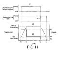
- FIG. 11 shows an operation pattern or mode in the image-erasing apparatus 80 of this eighth embodiment.
- the lower diagram (graph) of FIG. 11 shows the change in temperature and power with time.
- the vertical axis on the left side represents temperature, and the vertical axis on the right side represents power.
- the line 42 shows temperature changes in the image-erasing apparatus 80.
- the electric heaters 4 and 5 are activated, and the temperature starts to increase.
- the temperature reaches the erasing temperature.
- the erasing temperature is maintained until a time T3.
- the cooling down starts.
- the temperature returns to the room temperature.
- the erasable material develops color through the interaction between a color former and a developer included in the material.
- the color former preferentially dissolves with a binder resin in the material so that the material loses color.
- the decolorizer reacts with the developer so that the material loses color. The higher the temperature, the more quickly the reaction proceeds. However, if the temperature is too high, the paper will burn and become discolored.
- the erasing temperature is preferably 120°C to 150°C. By maintaining a temperature in this range for a few hours, the images can be substantially erased. According to experiments conducted by the inventors, in the case where the erasing temperature is maintained in the range of 120°C to 150°C, the time required for erasing was approximately an hour and a half to two hours.
- the line 43 shows power consumption of the image-erasing apparatus 80. As shown in FIG. 11, when the temperature increases, the power consumption is highest (P1). After the temperature reaches the erasing temperature and when the erasing temperature is maintained, the power consumption is reduced to P2 because the power is used only to compensate the heat loss due to the heat radiation. In the cooling process, the power to be consumed is further reduced to P3 because the power is used only for the operation of the blower fan 9.
- the upper diagram (graph) of FIG. 11 shows an operation of the photo catalyst.
- the middle diagram (graph) of FIG. 11 shows the operation of the blower fan 9.
- the blower fan 9 is stopped so as to increase the heating efficiency, and the photo-catalyst is operated to decompose the odor substances.
- the cooling process time T3 to time T4
- the operation of the photo-catalyst is stopped, and the blower fan 7 is driven.
- the bundle of sheets of paper 1 is surrounded by the tray 21 and heating plates 2 and 3. In addition, these are sandwiched between the heat-blocking plates 8a and 8b so as to prevent heat radiation.
- the electric heaters 4 and 5 are supported by spacers 6 and the elastic member 7, i.e., springs, respectively. Since the spacers 6 and the elastic member 7 have a low heat-transfer coefficient, the heat radiation from these supporting parts can also be prevented.
- the above-described structure reduces the average power consumption of the image-erasing apparatus 80, and the image-erasing apparatus 80 can be manufactured at a low cost.
- the image-erasing apparatus 80 can be used in an office having a 100V AC power supply.
- the power supply 35 of the substance treating unit 90 is operated so as to excite the voltage terminals 34 to thereby generate the electric discharge. Due to this electric discharge, a creeping discharge is generated on the surface of the photo catalyst carrier 33 between the voltage terminals 44. Due to this creeping discharge, ultraviolet radiation is emitted. As a result of being irradiated with this ultraviolet radiation, the photo-catalyst in the photo-catalyst carrier 33 is activated. According to the reaction of the photo-catalyst, the odor substances produced during the heating of the paper bundle 1 are decomposed.
- the inventors compared the case where the photo-catalyst was activated with the case where the photo-catalyst was not activated. In each case, an odor index at the vent port was measured. Table 1 shows the measurement results of the odor index.
- the odor indexes in Table 1 were calculated as follows. First, the exhaust including odorous substances was diluted until the concentration of the odorous substances was a predetermined value, and the dilution rate at that time was obtained. Next, the logarithm of the dilution rate was taken. Multiplying ten to the logarithm gave the odor index. Therefore, the smaller the odor index, the more odor substances were decomposed, that is to say, the more the exhaust was deodorized. Effect of Photo Catalyst Elapsed time Dilution rate Odor index 20 mins 60 mins 20 mins 60 mins Photo catalyst is activated 173 173 22 22 Photo catalyst is not activated 1700 550 32 27
- the odor index was 22 at 20 minutes after the start of the heating. This represented a low level odor index compared with the case where the photo-catalyst was not activated.
- the odor index did not change from the value at 20 minutes after the start of the heating. That is to say, due to the photo-catalyst reaction, the odor index was reduced immediately after the start of the heating. It was confirmed that the odor substances were decomposed and the exhaust was deodorized.
- the oxygen in the air reacts by the electric discharge between the voltage terminals 34 and the ozone is generated. Then, the odor substances are decomposed by the ozone.
- the blower fan 9 is driven and the operation of the power supply 35 is stopped. If the power supply 35 is operated in the cooling process (time T3 to time T4), the generated ozone is discharged by the blower fan 9, and hence, stopping the power supply 35 at time T3 prevents the discharge of ozone.
- the image-erasing apparatus 80 is provided with the ozone-removing device 37 for decomposing ozone, the discharge of ozone can be prevented more reliably.
- the photo-catalyst carrier 33 carries the photo-catalyst and is disposed between voltage terminals 44, so that the odor substances are decomposed by the light emitted through the electric discharge between the voltage terminals 44.
- the image-erasing apparatus 80 includes the ozone-removing device 37, the average power consumption can be made low, and the discharge of odor can be further reduced.
- the substances produced in the erasing process are odor substances
- the other chemicals can also be removed by using a suitable filter or a suitable adsorbent.
Landscapes
- Physics & Mathematics (AREA)
- General Physics & Mathematics (AREA)
- Cleaning In Electrography (AREA)
- Printing Plates And Materials Therefor (AREA)
Applications Claiming Priority (4)
| Application Number | Priority Date | Filing Date | Title |
|---|---|---|---|
| JP2003409436 | 2003-12-08 | ||
| JP2003409436A JP2005169677A (ja) | 2003-12-08 | 2003-12-08 | 画像消去装置 |
| JP2004143936A JP2005324417A (ja) | 2004-05-13 | 2004-05-13 | 画像形成材料の消去装置および消去方法 |
| JP2004143936 | 2004-05-13 |
Publications (2)
| Publication Number | Publication Date |
|---|---|
| EP1542093A2 true EP1542093A2 (de) | 2005-06-15 |
| EP1542093A3 EP1542093A3 (de) | 2007-12-05 |
Family
ID=34525491
Family Applications (1)
| Application Number | Title | Priority Date | Filing Date |
|---|---|---|---|
| EP04028858A Withdrawn EP1542093A3 (de) | 2003-12-08 | 2004-12-06 | Bildlöschapparat und Bildlöschmethode |
Country Status (4)
| Country | Link |
|---|---|
| US (1) | US7184069B2 (de) |
| EP (1) | EP1542093A3 (de) |
| KR (1) | KR20050055597A (de) |
| CN (1) | CN100412723C (de) |
Families Citing this family (8)
| Publication number | Priority date | Publication date | Assignee | Title |
|---|---|---|---|---|
| JPWO2006070434A1 (ja) * | 2004-12-27 | 2008-06-12 | オリエント測器コンピュータ株式会社 | データ記録媒体の廃棄処理方法 |
| JP2009089081A (ja) * | 2007-09-28 | 2009-04-23 | Fujifilm Corp | 文書処理装置、文書処理方法およびプログラム |
| JP5200722B2 (ja) * | 2008-07-17 | 2013-06-05 | 株式会社リコー | 画像記録装置 |
| US8319808B2 (en) * | 2010-05-25 | 2012-11-27 | Kabushiki Kaisha Toshiba | Image forming apparatus |
| WO2012011104A1 (en) * | 2010-07-22 | 2012-01-26 | Xjet Ltd. | Printing head nozzle evaluation |
| US9925817B2 (en) * | 2011-06-09 | 2018-03-27 | Kabushiki Kaisha Toshiba | Decolorizing apparatus |
| JPWO2013008845A1 (ja) * | 2011-07-13 | 2015-02-23 | 日本電産サンキョー株式会社 | カード印刷装置およびカード印刷装置の制御方法 |
| JP6240113B2 (ja) * | 2015-03-12 | 2017-11-29 | 株式会社東芝 | 画像形成装置及び消色装置 |
Family Cites Families (22)
| Publication number | Priority date | Publication date | Assignee | Title |
|---|---|---|---|---|
| US5237338A (en) * | 1991-08-05 | 1993-08-17 | Eastman Kodak Company | Is-enthalpic control of a thermal printing head |
| JPH05150540A (ja) * | 1991-11-28 | 1993-06-18 | Bando Chem Ind Ltd | 消色方法および消色装置 |
| JP3258359B2 (ja) * | 1992-03-19 | 2002-02-18 | 株式会社リコー | 感熱記録体の記録装置 |
| JPH07112738B2 (ja) * | 1992-04-08 | 1995-12-06 | 産電子工業株式会社 | 加熱により印字、消字可能の画像記録カ−ドの消字装置 |
| JPH05301417A (ja) * | 1992-04-27 | 1993-11-16 | Alps Electric Co Ltd | 画像消去装置 |
| JPH0615958A (ja) * | 1992-07-02 | 1994-01-25 | Ricoh Co Ltd | 消去装置 |
| JPH0624129A (ja) * | 1992-07-03 | 1994-02-01 | Ricoh Co Ltd | 画像消去方法 |
| JPH0647990A (ja) * | 1992-07-29 | 1994-02-22 | Alps Electric Co Ltd | 画像消去用加熱装置の制御方法 |
| JPH07175380A (ja) * | 1993-12-17 | 1995-07-14 | Bando Chem Ind Ltd | 消色装置 |
| JPH0839839A (ja) * | 1994-08-01 | 1996-02-13 | Oki Electric Ind Co Ltd | 熱記録媒体処理装置 |
| JPH0890934A (ja) * | 1994-09-22 | 1996-04-09 | Almex Inc | 熱可逆特性を有するリライトカードの印字方法と印字装置 |
| JPH08187050A (ja) * | 1995-01-09 | 1996-07-23 | Sumikin Hoton Ceramics Kk | 恒温乾燥装置 |
| JPH09305074A (ja) * | 1996-05-14 | 1997-11-28 | Fujitsu Isotec Ltd | 印字消色装置 |
| JP3674824B2 (ja) * | 1997-12-27 | 2005-07-27 | 株式会社リコー | 印字・消去方法 |
| JP3315360B2 (ja) | 1998-01-23 | 2002-08-19 | 株式会社東芝 | 消去可能な画像形成材料の消去方法 |
| JPH11231788A (ja) * | 1998-02-17 | 1999-08-27 | Asahi Optical Co Ltd | 画像消去装置 |
| JP2000033719A (ja) * | 1998-07-17 | 2000-02-02 | Ricoh Elemex Corp | リライタブル記録装置 |
| JP2000108392A (ja) * | 1998-10-07 | 2000-04-18 | Ricoh Elemex Corp | 熱可逆性記録媒体の消去装置 |
| JP2000191155A (ja) * | 1998-12-25 | 2000-07-11 | Seiko Epson Corp | 印刷装置 |
| JP2002254684A (ja) * | 2001-03-06 | 2002-09-11 | Matsushita Electric Ind Co Ltd | 可逆性感熱記録装置 |
| JP4127464B2 (ja) * | 2001-03-28 | 2008-07-30 | 大日精化工業株式会社 | 可消色性画像の消色方法 |
| JP3869243B2 (ja) * | 2001-10-16 | 2007-01-17 | リンテック株式会社 | 非接触型リライトサーマルラベル及びその使用方法 |
-
2004
- 2004-12-06 EP EP04028858A patent/EP1542093A3/de not_active Withdrawn
- 2004-12-06 US US11/004,002 patent/US7184069B2/en not_active Expired - Fee Related
- 2004-12-07 KR KR1020040102182A patent/KR20050055597A/ko not_active Ceased
- 2004-12-08 CN CNB2004100983767A patent/CN100412723C/zh not_active Expired - Fee Related
Also Published As
| Publication number | Publication date |
|---|---|
| EP1542093A3 (de) | 2007-12-05 |
| KR20050055597A (ko) | 2005-06-13 |
| US7184069B2 (en) | 2007-02-27 |
| US20050134670A1 (en) | 2005-06-23 |
| CN1627209A (zh) | 2005-06-15 |
| CN100412723C (zh) | 2008-08-20 |
Similar Documents
| Publication | Publication Date | Title |
|---|---|---|
| US7184069B2 (en) | Image-erasing apparatus and image-erasing method | |
| JP6374484B2 (ja) | 露光装置、および感光性要素を露光する方法、および感光性要素から印刷版を作製する方法 | |
| JP2003118075A (ja) | 平板印刷機の被印刷体に放射エネルギーを供給する装置および方法 | |
| JP2010036589A (ja) | 平板印刷機の被印刷体に放射エネルギーを供給する装置 | |
| EP2378379A2 (de) | Bilderzeugungsvorrichtung | |
| JP4908739B2 (ja) | 印刷機において被印刷体の上の印刷インキを乾燥させる方法および印刷機 | |
| JPH09305074A (ja) | 印字消色装置 | |
| KR20020032743A (ko) | 간접가열식 폐활성탄 열재생방법과 장치 | |
| KR100600705B1 (ko) | 습식 화상형성장치 및 그 제어방법 | |
| US7343116B2 (en) | Gas purifying apparatus, image forming apparatus having the same, and method of purifying gas of the image forming apparatus | |
| JP4546122B2 (ja) | 被印刷体の上の印刷インキを乾燥させる方法、およびこの方法を実施するのに適した印刷ユニット | |
| JP3874692B2 (ja) | 光触媒作用および加熱により変質可能な物質を伴う印刷用供給式回転印刷装置に使用される湿式オフセット・プリンティングフォームおよび印刷用供給式回転印刷装置に使用される湿式オフセット・プリンティングフォームのプリント・イメージを生成するためおよび/またはプリント・イメージを消去するための装置及び方法 | |
| JPH11254642A (ja) | 乾燥装置 | |
| JP2008112064A (ja) | 画像形成装置 | |
| CN102218934B (zh) | 卷筒纸印刷机 | |
| US20170341447A1 (en) | Removable dryer module for a printing apparatus | |
| JP2005324417A (ja) | 画像形成材料の消去装置および消去方法 | |
| JP2005169677A (ja) | 画像消去装置 | |
| KR20060071651A (ko) | 습식 화상형성장치 및 화상형성방법 | |
| JP4498114B2 (ja) | 画像消去装置 | |
| JP2001116458A (ja) | クリーンオーブン及びその使用方法 | |
| CN1740926A (zh) | 载体蒸气清洁器、湿式电子照相成像装置及其清洁方法 | |
| JP2008168560A (ja) | 紫外線照射装置、および同紫外線照射装置を備えた記録装置 | |
| JP4628214B2 (ja) | 画像形成装置 | |
| JPH07175380A (ja) | 消色装置 |
Legal Events
| Date | Code | Title | Description |
|---|---|---|---|
| PUAI | Public reference made under article 153(3) epc to a published international application that has entered the european phase |
Free format text: ORIGINAL CODE: 0009012 |
|
| 17P | Request for examination filed |
Effective date: 20041206 |
|
| AK | Designated contracting states |
Kind code of ref document: A2 Designated state(s): AT BE BG CH CY CZ DE DK EE ES FI FR GB GR HU IE IS IT LI LT LU MC NL PL PT RO SE SI SK TR |
|
| AX | Request for extension of the european patent |
Extension state: AL BA HR LV MK YU |
|
| RIC1 | Information provided on ipc code assigned before grant |
Ipc: B41M 7/00 20060101ALI20070810BHEP Ipc: G03G 21/00 20060101AFI20050329BHEP |
|
| PUAL | Search report despatched |
Free format text: ORIGINAL CODE: 0009013 |
|
| AK | Designated contracting states |
Kind code of ref document: A3 Designated state(s): AT BE BG CH CY CZ DE DK EE ES FI FR GB GR HU IE IS IT LI LT LU MC NL PL PT RO SE SI SK TR |
|
| AX | Request for extension of the european patent |
Extension state: AL BA HR LV MK YU |
|
| AKX | Designation fees paid |
Designated state(s): DE FR GB |
|
| 17Q | First examination report despatched |
Effective date: 20100330 |
|
| STAA | Information on the status of an ep patent application or granted ep patent |
Free format text: STATUS: THE APPLICATION IS DEEMED TO BE WITHDRAWN |
|
| 18D | Application deemed to be withdrawn |
Effective date: 20100810 |