EP1529958B1 - Ölzufuhrsystem für einen Verbrennungsmotor - Google Patents
Ölzufuhrsystem für einen Verbrennungsmotor Download PDFInfo
- Publication number
- EP1529958B1 EP1529958B1 EP04026034A EP04026034A EP1529958B1 EP 1529958 B1 EP1529958 B1 EP 1529958B1 EP 04026034 A EP04026034 A EP 04026034A EP 04026034 A EP04026034 A EP 04026034A EP 1529958 B1 EP1529958 B1 EP 1529958B1
- Authority
- EP
- European Patent Office
- Prior art keywords
- oil
- hydraulic
- outlet port
- passage
- valve
- Prior art date
- Legal status (The legal status is an assumption and is not a legal conclusion. Google has not performed a legal analysis and makes no representation as to the accuracy of the status listed.)
- Expired - Lifetime
Links
- 239000003921 oil Substances 0.000 claims description 144
- 239000010720 hydraulic oil Substances 0.000 claims description 141
- 238000007599 discharging Methods 0.000 claims description 48
- 238000002485 combustion reaction Methods 0.000 description 6
- 238000010586 diagram Methods 0.000 description 5
- XEEYBQQBJWHFJM-UHFFFAOYSA-N Iron Chemical compound [Fe] XEEYBQQBJWHFJM-UHFFFAOYSA-N 0.000 description 2
- 239000000956 alloy Substances 0.000 description 2
- 229910045601 alloy Inorganic materials 0.000 description 2
- 229910052751 metal Inorganic materials 0.000 description 2
- 239000002184 metal Substances 0.000 description 2
- 238000000034 method Methods 0.000 description 2
- 229910052782 aluminium Inorganic materials 0.000 description 1
- XAGFODPZIPBFFR-UHFFFAOYSA-N aluminium Chemical compound [Al] XAGFODPZIPBFFR-UHFFFAOYSA-N 0.000 description 1
- 230000000903 blocking effect Effects 0.000 description 1
- 244000309466 calf Species 0.000 description 1
- 230000006835 compression Effects 0.000 description 1
- 238000007906 compression Methods 0.000 description 1
- 230000003292 diminished effect Effects 0.000 description 1
- 229910052742 iron Inorganic materials 0.000 description 1
- 230000001050 lubricating effect Effects 0.000 description 1
- 238000005461 lubrication Methods 0.000 description 1
- 239000000203 mixture Substances 0.000 description 1
Images


Classifications
-
- F—MECHANICAL ENGINEERING; LIGHTING; HEATING; WEAPONS; BLASTING
- F04—POSITIVE - DISPLACEMENT MACHINES FOR LIQUIDS; PUMPS FOR LIQUIDS OR ELASTIC FLUIDS
- F04C—ROTARY-PISTON, OR OSCILLATING-PISTON, POSITIVE-DISPLACEMENT MACHINES FOR LIQUIDS; ROTARY-PISTON, OR OSCILLATING-PISTON, POSITIVE-DISPLACEMENT PUMPS
- F04C14/00—Control of, monitoring of, or safety arrangements for, machines, pumps or pumping installations
- F04C14/24—Control of, monitoring of, or safety arrangements for, machines, pumps or pumping installations characterised by using valves controlling pressure or flow rate, e.g. discharge valves or unloading valves
-
- F—MECHANICAL ENGINEERING; LIGHTING; HEATING; WEAPONS; BLASTING
- F04—POSITIVE - DISPLACEMENT MACHINES FOR LIQUIDS; PUMPS FOR LIQUIDS OR ELASTIC FLUIDS
- F04C—ROTARY-PISTON, OR OSCILLATING-PISTON, POSITIVE-DISPLACEMENT MACHINES FOR LIQUIDS; ROTARY-PISTON, OR OSCILLATING-PISTON, POSITIVE-DISPLACEMENT PUMPS
- F04C14/00—Control of, monitoring of, or safety arrangements for, machines, pumps or pumping installations
- F04C14/06—Control of, monitoring of, or safety arrangements for, machines, pumps or pumping installations specially adapted for stopping, starting, idling or no-load operation
- F04C14/065—Capacity control using a multiplicity of units or pumping capacities, e.g. multiple chambers, individually switchable or controllable
-
- F—MECHANICAL ENGINEERING; LIGHTING; HEATING; WEAPONS; BLASTING
- F04—POSITIVE - DISPLACEMENT MACHINES FOR LIQUIDS; PUMPS FOR LIQUIDS OR ELASTIC FLUIDS
- F04C—ROTARY-PISTON, OR OSCILLATING-PISTON, POSITIVE-DISPLACEMENT MACHINES FOR LIQUIDS; ROTARY-PISTON, OR OSCILLATING-PISTON, POSITIVE-DISPLACEMENT PUMPS
- F04C14/00—Control of, monitoring of, or safety arrangements for, machines, pumps or pumping installations
- F04C14/10—Control of, monitoring of, or safety arrangements for, machines, pumps or pumping installations characterised by changing the positions of the inlet or outlet openings with respect to the working chamber
- F04C14/12—Control of, monitoring of, or safety arrangements for, machines, pumps or pumping installations characterised by changing the positions of the inlet or outlet openings with respect to the working chamber using sliding valves
-
- F—MECHANICAL ENGINEERING; LIGHTING; HEATING; WEAPONS; BLASTING
- F04—POSITIVE - DISPLACEMENT MACHINES FOR LIQUIDS; PUMPS FOR LIQUIDS OR ELASTIC FLUIDS
- F04C—ROTARY-PISTON, OR OSCILLATING-PISTON, POSITIVE-DISPLACEMENT MACHINES FOR LIQUIDS; ROTARY-PISTON, OR OSCILLATING-PISTON, POSITIVE-DISPLACEMENT PUMPS
- F04C15/00—Component parts, details or accessories of machines, pumps or pumping installations, not provided for in groups F04C2/00 - F04C14/00
- F04C15/0088—Lubrication
- F04C15/0092—Control systems for the circulation of the lubricant
-
- F—MECHANICAL ENGINEERING; LIGHTING; HEATING; WEAPONS; BLASTING
- F04—POSITIVE - DISPLACEMENT MACHINES FOR LIQUIDS; PUMPS FOR LIQUIDS OR ELASTIC FLUIDS
- F04C—ROTARY-PISTON, OR OSCILLATING-PISTON, POSITIVE-DISPLACEMENT MACHINES FOR LIQUIDS; ROTARY-PISTON, OR OSCILLATING-PISTON, POSITIVE-DISPLACEMENT PUMPS
- F04C2/00—Rotary-piston machines or pumps
- F04C2/08—Rotary-piston machines or pumps of intermeshing-engagement type, i.e. with engagement of co-operating members similar to that of toothed gearing
- F04C2/10—Rotary-piston machines or pumps of intermeshing-engagement type, i.e. with engagement of co-operating members similar to that of toothed gearing of internal-axis type with the outer member having more teeth or tooth-equivalents, e.g. rollers, than the inner member
Definitions
- This invention generally relates to an oil supply system for an engine. More specifically, this invention relates to an oil supply system for an engine provided with a pump body including an inlet port suctioning hydraulic oil in response to the rotation of a rotor driven by synchronizing with a crankshaft and first and second outlet ports discharging the hydraulic oil in response to the rotation of the rotor.
- the oil supply system for the engine is further provided with a hydraulic-oil-delivery passage for delivering the hydraulic oil to a hydraulic-oil receiving unit, a first oil passage for delivering the hydraulic oil discharged out of at least the first outlet port to the hydraulic-oil-delivery passage and a second oil passage for delivering the hydraulic oil discharged out of the second outlet port to the hydraulic-oil-delivery passage.
- the oil supply system for the engine is further provided with a return hydraulic passage returning the hydraulic oil discharged out of a hydraulic-pressure control valve including a valve which is moved in response to hydraulic pressure of the hydraulic oil delivered to the hydraulic-oil-delivery passage, to at least either the inlet port or an oil pan.
- an oil pump i.e., an oil supply system
- delivering the hydraulic oil to be used for lubrication of the engine to each portion of the engine has a variable discharge volume structure variably adjusting discharging pressure in response to the rotation of the engine.
- the above mentioned oil supply system is shown in JPH08 (1996)-114186A and JP2598994Y .
- the oil supply system described in JPH08 (1996)-114186A is provided with an oil pump including the first outlet port and the second outlet port discharging the hydraulic oil in response to the rotation of the rotor and the hydraulic-oil-delivery passage delivering the hydraulic oil to the hydraulic-oil receiving unit.
- the oil supply system is further provided with the first oil passage delivering the hydraulic oil discharged out of the first outlet port to the hydraulic-oil-delivery passage, the second oil passage delivering the hydraulic oil discharged out of the second outlet port to the hydraulic-oil-delivery passage and the return oil passage returning the hydraulic oil discharged out of the second outlet port to the oil pump.
- the oil supply system includes a control valve including the valve operable in response to the hydraulic pressure of the hydraulic oil of the first oil passage.
- this control valve delivers the hydraulic oil via both the first oil passage and the second oil passage to the hydraulic-oil-delivery passage (i.e., a first mode).
- the control valve prevents the merging of the hydraulic oil flow in the first and the second oil passages and allows the hydraulic-oil in the first oil passage to be delivered to the hydraulic-oil -delivery passage, and forces the hydraulic oil in the second oil passage to be returned to the return oil passage (i.e., a second mode). Accordingly, the oil supply system is capable of switching from the first mode to the second mode or vice versa.
- a supply amount of the hydraulic oil delivered to the hydraulic-oil-delivery passage is a total amount of the discharging amount of the first outlet port (i.e., a main outlet port) and the discharging amount of the second outlet port (i.e., a sub-outlet port) (i.e., the first mode).
- the valve When the rotational speed of the rotor further increases and reaches at a point "Z" which is a second medium speed area, the valve further slides in the control valve to prevent merging of the hydraulic oil in the first oil passage and the second oil passage (i.e., the second mode).
- the discharging amount of the hydraulic oil discharged out of the oil supply system is on a chain line "b" in Fig. 9 which shows the discharging amount at the first outlet port.
- the discharging amount In a high-speed area, thereafter, the discharging amount has an approximately similar characteristic to the chain line "b" thereafter. That is, the supply amount of the hydraulic oil delivered to the hydraulic-oil-delivery passage becomes approximately equal to the discharging amount of the first outlet port.
- the required hydraulic pressure delivered to the hydraulic-oil receiving unit is secured by merging of the hydraulic oil in the first oil passage and the hydraulic oil in the second oil passage.
- the first mode is shifted to the second mode wherein the extra hydraulic oil discharged out of the second outlet port in the second oil passage is returned to the inlet port side via the return oil passage.
- the extra hydraulic oil would not be affected by a large hydraulic pressure: Accordingly, when the required hydraulic pressure is secured by the first oil passage only, an additional work in the oil pump device can be reduced or avoided and the driving horsepower of the oil supply system can be reduced.
- the required oil amount corresponds to the discharging amount of the hydraulic oil discharged out of the oil supply system i.e., the total discharging amount (shown by a dotted line "a" in Fig. 9) adding up the discharging amount of the first and second outlet ports.
- an oil supply system for an engine includes a pump body including an inlet port for suctioning a hydraulic oil in response to the rotation of a rotor driven by synchronizing with a crankshaft, a first outlet port for discharging the hydraulic oil and a second outlet port for discharging the hydraulic oil in response to the rotation of the rotor and a hydraulic-oil-delivery passage for delivering the hydraulic oil to a hydraulic-oil receiving unit.
- the oil supply system for the engine further includes a first oil passage for delivering the hydraulic oil discharged out of the first outlet port to the hydraulic-oil-delivery passage, a second oil passage for delivering the hydraulic oil discharged out of the second outlet port to the hydraulic-oil-delivery passage and a return hydraulic passage for returning the hydraulic oil discharged out of a hydraulic-pressure control valve including a valve body which is moved in response to the hydraulic pressure delivered to the hydraulic-oil-delivery passage, to at least either the inlet port or an oil pan.
- the valve body divides a hydraulic-oil receiving portion for receiving the hydraulic oil in the hydraulic-pressure control valve chamber into a first valve chamber and a second valve chamber.
- the hydraulic oil discharged out of the second outlet port is delivered to the hydraulic-oil-delivery passage via the first valve chamber. Further when the pressure of the hydraulic oil delivered to the hydraulic-oil-delivery passage exceeds the predetermined value, the hydraulic oil discharged out of the second outlet port is delivered to the hydraulic-oil-delivery passage via the second valve chamber.
- FIG. 1 is a conceptual arrangement of an oil supply system of this embodiment of the present invention.
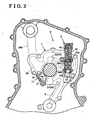
- Fig. 2 is a schematic layout of the oil supply system of the present invention mounted in the engine.
- the oil supply system X for the engine of the present invention is provided with a pump body 1 including an inlet port 36 suctioning a hydraulic oil in response to the rotation of a rotor 2 driven by synchronizing with a crankshaft, a first outlet port 31 discharging the hydraulic oil and a second outlet port 32 discharging the hydraulic oil therefrom.
- the oil supply system X for the engine is further provided with a hydraulic-oil-delivery passage 5 for delivering the hydraulic oil to a hydraulic-oil receiving unit 7, a first oil passage 61 for delivering the hydraulic oil discharged out of the first outlet port 31 to the hydraulic-oil-delivery passage 5 at least and a second oil passage 62 for delivering the hydraulic oil discharged out of the second outlet port 32 to the hydraulic-oil-delivery passage 5.
- the oil supply system for the engine is further provided with a return hydraulic passage 66 returning the hydraulic oil discharged out of a hydraulic-pressure control valve 4 including a valve 47 which is moved in response to hydraulic pressure of the hydraulic oil delivered to the hydraulic-oil-delivery passage 5, to at least either the inlet port 36 or a oil pan 69.
- the pump body 1 according to the oil supply system X is made of metal, such as an aluminum-based alloy and an iron-based alloy.
- a pump chamber 10 is formed in the pump body 1.
- an internal gear portion 12 having a plurality of inner gears 11 serving as a driven gear is formed.
- the rotor 2 made of metal is rotatably disposed therein.
- the rotor 2 is connected to the crankshaft of the internal combustion engine which constitutes the driving force, and rotates with the crankshaft.
- the rotor 2 is designed to rotate at 600 rpm to 7000 rpm.
- an outer gear portion 22 having a plurality of external gears 21 serving as the drive gear is formed on an outer periphery of the rotor 2.
- the internal gears 11 and the external gears 21 are defined by such as a trochoid curve or a cycloidal curve.
- the rotor 2 rotates in a direction of an arrow "A1" as illustrated Fig. 1.
- the external gears 21 of the rotor 2 mesh with the internal gears 11 one after another in response to the rotation of the rotor 2. Accordingly the internal gears 12 rotates in the same direction.
- Spaces 22a through 22k are formed by the external gears 21 and the internal gears 11. In Fig. 1, the space 22k has the largest volume among the spaces 22a through 22k, and the space 22e and 22f have the smallest volume.
- spaces 22e through 22a go downstream, their volume is enlarged gradually as the rotor 2 rotates. An inlet pressure of the hydraulic oil is produced thereby and an inlet action of the hydraulic oil is obtained. In spaces 22j through 22f, the discharging pressure is produced since their volume is diminished gradually when the rotor 2 rotates.
- an outlet port group 33 is formed by the first outlet port 31 (i.e., a main outlet port) and the second outlet port 32 (i.e., a sub-outlet port). That is, the outlet port group 33 serves as discharging the hydraulic oil from the pump chamber 10 in response to the rotation of the rotor 2.
- the main outlet port 31 is provided with end sides 31a and 31c.
- the sub-outlet port 32 is provided with end sides 32a and 32c.
- the inlet port 36 is formed as well.
- the inlet port 36 serves to suction the hydraulic oil into the pump body 10 in response to the rotation of the rotor 2.
- the inlet port 36 is provided with end sides 36a and 36c.
- the main outlet port 31 is located at the downstream side relative to the sub-outlet port 32 in the rotary direction of the rotor 2 indicated by the arrow "A1".
- An open area of the main outlet port 31 is set to be larger than the open area of the sub-outlet port 32.
- the main outlet port 31 and the sub-outlet port 32 are divided by a dividing portion 37. Thereby the main outlet port 31 and the sub-outlet port 32 have independent discharging-function respectively.
- the width of the dividing portion 37 is set to be narrower than the width of space between inner and outer gears at the area between the main outlet port 31 and the sub-outlet port 32.
- the hydraulic-oil-delivery passage 5 is a hydraulic-oil passage delivering the hydraulic oil to the hydraulic-oil receiving unit 7.
- the hydraulic-oil receiving unit 7 may be a lubricating device such as a bearing, a valve operation mechanism for an internal combustion engine or a driving mechanism such as a cylinder and a piston of the internal combustion engine, which are required to supply the hydraulic oil.
- the first oil passage 61 is the oil passage which connects the main outlet port 31 to the hydraulic-oil-delivery passage 5. That is, the first oil passage 61 has the function which delivers the hydraulic oil discharged out of the main outlet port 31 to the hydraulic-oil-delivery passage 5.
- the second oil passage 62 is the oil passage which connects the sub-outlet port 32 to the hydraulic-oil-delivery passage 5. That is, the second oil passage 62 has the function which delivers the hydraulic oil discharged out of the sub-outlet port 32 to the hydraulic-oil-delivery passage 5.
- Fig. 1 shows an example of the function that the hydraulic oil discharged out of the sub-outlet port 32 flows through the hydraulic-pressure control valve 4 and the main outlet port 31, then flows to the hydraulic-oil-delivery passage 5 via the first oil passage 61.
- the return hydraulic passage 66 is an oil passage which returns the hydraulic oil discharged out of the hydraulic control valve 4 to any one of the inlet port 36 and an oil pan 69.
- a passage 66n which suctions the hydraulic oil out of the oil pan 69 is disposed in communication with the inlet port 36.
- the hydraulic-pressure control valve 4 is provided with a valve 47 which moves in response to the hydraulic pressure of the hydraulic oil delivered to the hydraulic-oil-delivery passage 5.
- the hydraulic control valve 4 is further provided with a valve chamber 40 in which the valve 47 is freely slidable. In the valve chamber 40, the valve 47 is disposed by biased by a spring 49 in the direction of the arrow "B1".
- a first valve portion 47x and a second valve portion 47y which compose a hydraulic-oil receiving portion 48 which receives the hydraulic oil within hydraulic-pressure control valve 4 are disposed. Further in the valve 47, a dividing body 47a which divides the hydraulic-oil receiving portion 48 into a first valve chamber 48a and a second valve chamber 48b is disposed.
- a first valve port 41, a second valve port 42, return ports 43a and 43b and a merging port 44 which communicate with each described oil passage are disposed.
- the first valve port 41 communicates with the first oil passage 61 and the hydraulic-oil-delivery passage 5 via an intermediate oil passage 61r.
- the hydraulic pressure of the hydraulic oil can be transmitted to the valve 47 via the intermediate oil passage 61 thereby.
- the second valve port 42 is capable of communicating with the second oil passage 62.
- the hydraulic oil discharged out of the second outlet port 32 can be discharged to the hydraulic-oil receiving portion 48 thereby.
- the return ports 43a and 43b are capable of communicating with the return hydraulic passage 66.
- the hydraulic discharged out of the hydraulic control valve 4 can be returned to the inlet port 36 thereby.
- the merging port 44 is capable of communicating with the main outlet port 31 so as to deliver the hydraulic oil discharged out of the hydraulic-pressure control valve 4 to the main outlet port 31.
- the valve 47 of the hydraulic-pressure control valve 4 have five modes i.e., modes A through E, according to the rotational speed of the rotor 2 as described hereinbelow.
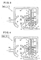
- the first valve portion 47x of the valve 47 blocks the return port 43a and the second valve portion 47y of the valve 47 blocks the return port 43b respectively.
- the second valve port 42 is in communication with the merging port 44 as shown in Fig. 3.
- the hydraulic oil discharged out of the sub-outlet port 32 can be delivered to the hydraulic-oil-delivery passage 5 via the first valve chamber 48a. That is, the hydraulic oil discharged out of the sub-outlet port 32 can be delivered to the hydraulic-oil-delivery passage 5 via the first valve chamber 48a when the hydraulic pressure delivered to the hydraulic-oil-delivery passage 5 is within a predetermined value (range).
- a supply amount of the hydraulic oil delivering to the hydraulic-oil-delivery passage 5 is the total amount of the discharging amount of the main outlet port 31 and the discharging amount of the sub-outlet port 32.
- An oil amount delivered to the hydraulic-oil-delivery passage 5 has a characteristic performance as shown by a solid line O-P in Fig. 8. That is, the discharging amount of the hydraulic oil discharged out of the main outlet port 31 increases according to the increase of the rotational speed of the rotor 2. Further, the discharging amount of the hydraulic oil discharged out of the sub-outlet port 32 increases according to the increase of the hydraulic pressure in the first oil passage 61. The characteristic performance that the hydraulic pressure in the second oil passage 62 increases can be obtained.
- the rotational speed of the rotor 2 increases according to the increase of the rotational speed of the crankshaft of the internal combustion engine working as the driving power force.
- N1 predetermined rotational speed
- the valve driving force "F1” overcomes the biasing force "F3" of the spring 49 (F1 > F3)
- the valve 47 moves in the direction of an arrow "B2” until the valve driving force "F1” and the urging force "F3” of the spring 49 balance (see Fig. 1).
- the mode “B” shows an intermediate mode wherein the valve 47 is shifting to the mode "C” described later.
- the hydraulic oil discharged out of the sub-outlet port 32 can be delivered to the return hydraulic passage 66 in part and the rest is delivered to the hydraulic-oil-delivery passage 5 via the first valve chamber 48a.
- the supply amount of the hydraulic oil delivered to the hydraulic-oil-delivery passage 5 is the total discharging amounts of the main outlet port 31 and the discharging amount of the sub-outlet port 32.
- the oil amount delivered to the hydraulic-oil-delivery passage 5 has a characteristic performance as indicated by a solid line P-Q in Fig. 8. Accordingly, a rate of the increase in the discharging amount relative to the increase of the rotational speed of the rotor reduces since a passage returning to the return hydraulic passage 66 communicates.
- a relationship between a required oil amount of a variable valve timing control device working as the hydraulic-oil receiving unit 7 and the rotational speed of the rotor in the engine will be described hereinbelow.
- the total discharged amount which adds the discharging amount of the sub-outlet port 32 to the discharging amount of the main outlet port 31 is required.
- the rotational speed of the rotor exceeds the predetermined rotational speed (N1), the total discharged amount is not required.
- the required oil amount can be provided by the discharging amount of the main outlet port 31 only (i.e., an area shown by "V" in Fig. 8). Accordingly, it is preferable that the oil supply system X is composed so that each inclination of line O-P and line P-Q shown in Fig. 8 can exceed the required oil amount V required for the variable valve timing control device.
- the hydraulic oil discharged out of the main outlet port 31 is delivered to the hydraulic-oil-delivery passage 5.
- the hydraulic oil discharged out of the sub-outlet port 32 can be delivered to the return hydraulic passage 66 via the first valve chamber 48a.
- the oil amount delivered to the hydraulic-oil-delivery passage 5 has a characteristic performance as indicated by a solid line Q-R in Fig. 8. That is, in the mode "C", the oil amount delivered to the hydraulic-oil-delivery passage 5 is equal to the oil amount discharged out of the main outlet port 31.
- the second valve port 42 communicates with the merging port 44 and the dividing chamber 47a prevents the hydraulic oil from moving to the return port 43a. Accordingly, the hydraulic oil discharged out of the sub-outlet port 32 can be delivered to the hydraulic-oil-delivery passage 5 via the second valve chamber 48b.
- the hydraulic oil discharged out of the sub-outlet port 32 can be delivered to the hydraulic-oil-delivery passage 5 via the second valve chamber 48b.
- the supply amount of the hydraulic oil delivered to the hydraulic-oil-delivery passage 5 is the total amount of the discharging amounts discharged out of the main outlet port 31 and the sub-outlet port 32.
- the oil amount delivered to the hydraulic-oil-delivery passage 5 has a characteristic performance as indicated by a solid line R-T in Fig. 8.
- the hydraulic oil delivered to stops flowing to the return port 43a After that reason, the flowing route of the hydraulic oil delivered to the return port 43a is changed to the hydraulic-oil-delivery passage 5. Therefore, the supply amount delivered to the hydraulic-oil-delivery passage 5 increases (see a solid line R-S in Fig. 8) and becomes the total amount of the discharging amounts discharged out of the main outlet port 31 and the sub-outlet port 32 (i.e., a solid line S-T in Fig. 8).
- the total amount is a part of the discharging amount of the main outlet port 31 and a part of the discharging amount of the sub-outlet port 32.
- the oil amount delivered to the hydraulic-oil-delivery passage 5 has a characteristic performance as indicated by a solid line T-U in Fig. 8.
- the rate of the increase in the discharging amount relative to the increase of the rotational speed of the rotor reduces since the passages returning to the return hydraulic passage 66 are in open communication.
- the required oil amount of a jet for a piston operating as the hydraulic-oil receiving unit 7 and the rotational speed of the rotor will be described hereinbelow.
- the total discharging amount of the discharging amount of the main outlet port 31 and the sub-outlet port 32 is required around the high-speed area in the rotation of the rotor.
- the rotational speed of the rotor exceeds the predetermined rotational speed (N4) of the rotor, the total discharging amount is not required (i.e., an area shown by "W" in Fig. 8).
- the oil supply system X is composed so that the inclination of the line T-U shown in Fig. 8 can exceed the required oil amount "W" of the jet for the piston.
- the hydraulic pressure of the hydraulic oil working to the hydraulic-oil-delivery passage 5 is in the predetermined value (range)
- the hydraulic oil discharged out of the sub-outlet port 32 can be delivered to the hydraulic-oil-delivery passage 5 via the first valve chamber 48a.
- the supply amount of hydraulic oil delivered to the hydraulic-oil-delivery passage 5 is the amount wherein the discharging amount discharged out of the main outlet port 31 and the discharging amount discharged out of the sub-outlet port 32 are added (i.e., the solid line O-P shown in Fig. 8).
- the required hydraulic pressure is secured up in the first oil passage 61 only, the required hydraulic pressure is returned to the return oil hydraulic passage 66 without delivering the extra hydraulic oil in the second oil passage 62 to the hydraulic-oil-delivery passage 5.
- the high hydraulic pressure does not affect the extra hydraulic oil.
- the hydraulic oil is required to supply to a lot of pistons immediately.
- the oil supply system X is composed so that the hydraulic oil discharged out of the sub-outlet port 32 can be delivered to the hydraulic-oil-delivery passage 5 via the second valve chamber 48b.
- the supply amount of the hydraulic oil delivering to the hydraulic-oil-delivery passage 5 is the added amount of the discharging amount of the main outlet port 31 and the discharging amount of the sub-outlet port 32 (i.e., a solid line S-T shown in Fig. 8).
- a moving-direction dimension L1 of the first valve chamber 48a and a moving-direction dimension L2 of the second valve chamber 48b are designed as follows.
- a design method of the moving-direction dimension L1 of the first valve chamber 48a will be illustrated by an example.
- the second valve port 42 communicates with the merging port 44. That is, the first valve chamber 48a communicates with the first outlet port 31.
- the oil supply system X is composed so as to keep the return port 43a closing.
- the second valve port 42 communicates with the merging port 44, and the return port 43a is secured closing by slidably moving of the valve 47 in the valve chamber 40. That is, the first valve chamber 48a is composed so as to communicate with the return hydraulic passage 66.
- the first valve chamber 48a when the first valve chamber 48a communicates with the second oil passage 62, the first valve chamber 48a is composed so as to communicate with at least either first outlet port 31 or return hydraulic passage 66.
- the merging port 44 starts communicating with the second valve port 42 at just an under surface of the dividing chamber 47a defining an under surface of the first valve chamber 48a and an upper surface of the second valve chamber 48b, i.e., the second calve chest 48b.
- the second valve port 42 communicates with the merging port 44, and the return port 43a is secured closing. That is, the second valve chamber 48b is composed so as to communicate with the return hydraulic passage 66.
- the second valve chamber 48b when the second valve chamber 48b communicates with the second oil passage 62, the second valve chamber 48b is composed so as to communicate with at least either first outlet port 31 or return hydraulic passage 66.
- the moving-direction dimension L1 of the first valve chamber 48a and the moving-direction dimension L2 of the second valve chamber 48b require a relationship of an accurate dimension.
Landscapes
- Engineering & Computer Science (AREA)
- Mechanical Engineering (AREA)
- General Engineering & Computer Science (AREA)
- Physics & Mathematics (AREA)
- Fluid Mechanics (AREA)
- Lubrication Of Internal Combustion Engines (AREA)
- Rotary Pumps (AREA)
Claims (5)
- Ölzufuhrsystem (X) für einen Motor, mit
einem Pumpenkörper (1), der eine Einlassöffnung (36) zum Ansaugen eines Hydrauliköls als Antwort auf die Drehung eines Rotors (2), der durch Synchronisieren mit einer Kurbelwelle angetrieben wird, eine erste Auslassöffnung (31) zum Abgeben des Hydrauliköls und eine zweite Auslassöffnung (32) zum Abgeben des Hydrauliköls als Antwort auf die Drehung des Rotors (2) aufweist,
einem Hydraulikölzufuhrdurchlass (5) zum Zuführen des Hydrauliköls zu einer Hydraulikölaufnahmeeinheit (7),
einem ersten Öldurchlass (61) zum Zuführen des Hydrauliköls, das von der ersten Auslassöffnung (31) abgegeben wird, zu dem Hydraulikölzufuhrdurchlass (5),
einem zweiten Öldurchlass (62) zum Zuführen des Hydrauliköls, das von der zweiten Auslassöffnung (32) abgegeben wird, zu dem Hydraulikölzufuhrdurchlass (5), und
einem Rückführhydraulikdurchlass (66) zum Zurückführen des Hydrauliköls, das abgegeben wird von einem Hydraulikdrucksteuerventil (4) mit einem Ventilkörper (47), der als Antwort auf den Hydraulikdruck bewegt wird, der dem Hydraulikölzufuhrdurchlass (5) zugeführt wird, an mindestens entweder die Einlassöffnung (36) oder eine Ölwanne (69),
dadurch gekennzeichnet, dass der Ventilkörper (47) einen Hydraulikölaufnahmeabschnitt zum Aufnehmen des Hydrauliköls in dem Hydraulikdruckregelventil (4) in eine erste Ventilkammer (48a) und eine zweite Ventilkammer (48b) teilt, und, wenn der Druck des Hydrauliköls, das dem Hydraulikölzufuhrdurchlass (5) zugeführt wird, einen vorbestimmten Wert nicht übersteigt, das Hydrauliköl, das von der zweiten Auslassöffnung (32) abgegeben wird, dem Hydraulikölzufuhrdurchlass (5) über die erste Ventilkammer (48a) zugeführt wird, und weiter, wenn der Druck des Hydrauliköls, das dem Hydraulikölzüfuhrdurchlass (5) zugeführt wird, den vorbestimmten Wert übersteigt, das Hydrauliköl, das von der zweiten Auslassöffnung (32) abgegeben wird, dem Hydraulikölzufuhrdurchlass (5) über die zweite Ventilkammer (48b) zugeführt wird. - Ölzufuhrsystem (X) für einen Motor nach Anspruch 1, bei dem die erste Ventilkammer (48a) angepasst ist zum Kommunizieren mit mindestens der ersten Auslassöffnung (31) oder dem Rückführöldurchlass (66), wenn die erste Ventilkammer (48a) mit dem zweiten Öldurchlass (62) kommuniziert.
- Ölzufuhrsystem (X) für einen Motor nach Anspruch 1 oder 2, bei dem die zweite Ventilkammer (48b) angepasst ist zum Kommunizieren mit mindestens der ersten Auslassöffnung (31) oder dem Rückführöldurchlass (66), wenn die zweite Ventilkammer (48b) mit dem zweiten Öldurchlass (62) kommuniziert.
- Ölzufuhrsystem (X) für einen Motor nach einem der vorhergehenden Ansprüche, bei dem die erste Ventilkammer (48a) oder die zweite Ventilkammer (48b) mit der ersten Auslassöffnung (31) und dem Rückführöldurchlass (66) kommuniziert, wenn die erste Ventilkammer (48a) oder die zweite Ventilkammer (48b) mit dem zweiten Öldurchlass (62) kommuniziert.
- Ölzufuhrsystem (X) für einen Motor nach einem der vorhergehenden Ansprüche, bei dem die erste Auslassöffnung (31) und die zweite Auslassöffnung (32) durch einen Teilungsabschnitt (37) geteilt sind, die Breite des Teilungsabschnitts (37) so festgelegt ist, dass sie schmaler ist als die Breite eines Raums zwischen Innen- und Außenzahnrad (11 und 12) in dem Bereich zwischen der ersten Auslassöffnung (31) und der zweiten Auslassöffnung (32).
Applications Claiming Priority (2)
| Application Number | Priority Date | Filing Date | Title |
|---|---|---|---|
| JP2003377530A JP4366645B2 (ja) | 2003-11-06 | 2003-11-06 | エンジンの油供給装置 |
| JP2003377530 | 2003-11-06 |
Publications (3)
| Publication Number | Publication Date |
|---|---|
| EP1529958A2 EP1529958A2 (de) | 2005-05-11 |
| EP1529958A3 EP1529958A3 (de) | 2005-10-19 |
| EP1529958B1 true EP1529958B1 (de) | 2008-01-02 |
Family
ID=34431324
Family Applications (1)
| Application Number | Title | Priority Date | Filing Date |
|---|---|---|---|
| EP04026034A Expired - Lifetime EP1529958B1 (de) | 2003-11-06 | 2004-11-03 | Ölzufuhrsystem für einen Verbrennungsmotor |
Country Status (4)
| Country | Link |
|---|---|
| US (1) | US7011069B2 (de) |
| EP (1) | EP1529958B1 (de) |
| JP (1) | JP4366645B2 (de) |
| DE (1) | DE602004010989T2 (de) |
Cited By (1)
| Publication number | Priority date | Publication date | Assignee | Title |
|---|---|---|---|---|
| DE102010019044A1 (de) | 2010-05-03 | 2011-11-03 | Geräte- und Pumpenbau GmbH Dr. Eugen Schmidt | Schmierstoffventil für Ölpumpen von Verbrennungsmotoren |
Families Citing this family (49)
| Publication number | Priority date | Publication date | Assignee | Title |
|---|---|---|---|---|
| DE10350632A1 (de) * | 2003-10-29 | 2005-06-16 | Gkn Sinter Metals Gmbh | Doppel- oder Mehrfachpumpe |
| FR2898294A1 (fr) | 2006-03-08 | 2007-09-14 | Eaux Minerales D Evian Saeme S | Dispositif d'injection/soufflage pour la fabrication d'un corps creux et procede |
| US8360746B2 (en) * | 2006-05-10 | 2013-01-29 | Metaldyne Company, Llc | Inverted pressure regulating valve for an engine oil pump |
| JP2007309234A (ja) * | 2006-05-19 | 2007-11-29 | Honda Motor Co Ltd | 内燃機関の潤滑装置 |
| JP4687991B2 (ja) | 2006-11-07 | 2011-05-25 | アイシン精機株式会社 | エンジンの油供給装置 |
| EP1959143B1 (de) | 2007-02-13 | 2010-10-20 | Yamada Manufacturing Co., Ltd. | Vorrichtung zum Steuern des Ölpumpendrucks |
| JP4796026B2 (ja) * | 2007-02-13 | 2011-10-19 | 株式会社山田製作所 | オイルポンプにおける圧力制御装置 |
| JP4521005B2 (ja) * | 2007-02-20 | 2010-08-11 | 株式会社山田製作所 | オイルポンプにおける圧力制御装置 |
| KR100844460B1 (ko) | 2007-07-11 | 2008-07-07 | (주)광일기공 | 엑스트라 오일 압력을 이용한 가변형 오일 펌프 |
| GB2452493B (en) | 2007-09-05 | 2012-05-23 | Bamford Excavators Ltd | Pumping apparatus |
| US11493037B1 (en) | 2014-05-21 | 2022-11-08 | Laverne Schumann | Pump system |
| US12129849B2 (en) | 2009-09-24 | 2024-10-29 | Laverne Schumann | Pump system |
| US8801396B2 (en) | 2010-06-04 | 2014-08-12 | Chrysler Group Llc | Oil pump system for an engine |
| US9394901B2 (en) | 2010-06-16 | 2016-07-19 | Kevin Thomas Hill | Pumping systems |
| JP5535848B2 (ja) | 2010-09-16 | 2014-07-02 | 本田技研工業株式会社 | 可変流量オイルポンプを備えたエンジン |
| JP5364068B2 (ja) * | 2010-09-30 | 2013-12-11 | アイシン・エィ・ダブリュ工業株式会社 | 歯車ポンプ |
| KR101534878B1 (ko) * | 2010-12-01 | 2015-07-07 | 현대자동차주식회사 | 가변오일펌프 |
| JP5278775B2 (ja) | 2010-12-06 | 2013-09-04 | アイシン精機株式会社 | 油供給装置 |
| GB2486195A (en) * | 2010-12-06 | 2012-06-13 | Gm Global Tech Operations Inc | Method of Operating an I.C. Engine Variable Displacement Oil Pump by Measurement of Metal Temperature |
| JP5278779B2 (ja) | 2010-12-21 | 2013-09-04 | アイシン精機株式会社 | オイルポンプ |
| KR101261141B1 (ko) * | 2010-12-23 | 2013-05-06 | 명화공업주식회사 | 2단 릴리프 밸브를 구비한 엔진용 오일공급장치 |
| JP5564450B2 (ja) * | 2011-02-17 | 2014-07-30 | 日立オートモティブシステムズ株式会社 | オイルポンプ |
| JP5374550B2 (ja) * | 2011-07-12 | 2013-12-25 | 本田技研工業株式会社 | オイルポンプのリリーフ装置 |
| DE112011105510B4 (de) * | 2011-08-10 | 2017-11-23 | Toyota Jidosha Kabushiki Kaisha | Ölzufuhrvorrichtung für einen Verbrennungsmotor |
| US9752581B2 (en) | 2011-11-07 | 2017-09-05 | Aisin Seiki Kabushiki Kaisha | Oil supply apparatus |
| JP5541537B2 (ja) * | 2011-11-07 | 2014-07-09 | アイシン精機株式会社 | オイル供給装置 |
| JP5849620B2 (ja) * | 2011-11-07 | 2016-01-27 | アイシン精機株式会社 | オイル供給装置 |
| KR101270914B1 (ko) | 2011-12-02 | 2013-06-03 | 명화공업주식회사 | 가변 오일 펌프 |
| JP5392797B2 (ja) * | 2011-12-02 | 2014-01-22 | ミュンフワ アイエヌディー. カンパニー,リミテッド | 可変オイルポンプ |
| JP2013253539A (ja) * | 2012-06-06 | 2013-12-19 | Aisin Seiki Co Ltd | オイル供給装置 |
| JP5993291B2 (ja) * | 2012-11-27 | 2016-09-14 | 日立オートモティブシステムズ株式会社 | 可変容量形ポンプ |
| JP6422242B2 (ja) * | 2013-07-30 | 2018-11-14 | 株式会社山田製作所 | オイルポンプ |
| JP6267526B2 (ja) * | 2014-01-29 | 2018-01-24 | 株式会社Subaru | 流体ポンプの流量制御装置 |
| US11365732B1 (en) | 2014-05-21 | 2022-06-21 | Laverne Schumann | High volume pump system |
| WO2016014978A1 (en) * | 2014-07-24 | 2016-01-28 | Schumann Laverne | Pump system |
| JP2016070219A (ja) * | 2014-09-30 | 2016-05-09 | 株式会社山田製作所 | オイルポンプ構造 |
| KR101724912B1 (ko) * | 2015-09-30 | 2017-04-07 | 현대자동차주식회사 | 기계식 가변 릴리프 오일펌프 구조 |
| KR102463186B1 (ko) * | 2016-12-13 | 2022-11-03 | 현대자동차 주식회사 | 차량용 피스톤 냉각 장치 |
| KR102613583B1 (ko) * | 2016-12-30 | 2023-12-14 | 명화공업주식회사 | 가변 오일 펌프 |
| KR102611538B1 (ko) * | 2016-12-30 | 2023-12-08 | 명화공업주식회사 | 오일펌프용 릴리프 밸브의 플런저 테이퍼부의 각도 설계 방법 |
| KR102068150B1 (ko) * | 2018-06-15 | 2020-01-20 | 명화공업주식회사 | 릴리프밸브 및 이를 포함하는 오일펌프 |
| CN109469528A (zh) * | 2018-12-28 | 2019-03-15 | 杭州电子科技大学 | 一种变排量内转子式机油泵 |
| CN109681760A (zh) * | 2019-01-04 | 2019-04-26 | 杭州电子科技大学 | 一种变排量叶片式机油泵及其供油方法 |
| CN109435506B (zh) * | 2019-01-16 | 2023-10-27 | 杭州米氪科技有限公司 | 安全印章 |
| CN110454382B (zh) * | 2019-08-31 | 2020-12-25 | 镇江沃尔夫重工部件有限公司 | 一种内啮合变量齿轮泵 |
| CN110469500B (zh) * | 2019-08-31 | 2021-01-15 | 上海如迪流体输送设备有限公司 | 一种恒压变量泵 |
| KR20210074724A (ko) * | 2019-12-12 | 2021-06-22 | 현대자동차주식회사 | 바이패스 구간이 분리된 오일펌프용 릴리프 밸브 어셈블리 |
| CN114878171B (zh) * | 2022-04-14 | 2025-05-16 | 中国航发沈阳发动机研究所 | 一种基于核心机的发动机起动供油规律设计方法 |
| CN116771460B (zh) * | 2023-08-17 | 2023-11-07 | 潍坊力创电子科技有限公司 | 液压全升程连续可变气门系统 |
Family Cites Families (6)
| Publication number | Priority date | Publication date | Assignee | Title |
|---|---|---|---|---|
| DE1145929B (de) | 1955-07-23 | 1963-03-21 | Teves Kg Alfred | Drehkolbenpumpe |
| US3067689A (en) * | 1958-10-06 | 1962-12-11 | Gen Motors Corp | Variable capacity fluid supply |
| JP2598994B2 (ja) | 1988-11-14 | 1997-04-09 | 富士写真フイルム株式会社 | 感光性組性物 |
| JP3531769B2 (ja) * | 1994-08-25 | 2004-05-31 | アイシン精機株式会社 | オイルポンプ装置 |
| CA2159672C (en) | 1994-10-17 | 2009-09-15 | Siegfried A. Eisenmann | A valve train with suction-controlled ring gear/internal gear pump |
| US5722815A (en) * | 1995-08-14 | 1998-03-03 | Stackpole Limited | Three stage self regulating gerotor pump |
-
2003
- 2003-11-06 JP JP2003377530A patent/JP4366645B2/ja not_active Expired - Fee Related
-
2004
- 2004-11-01 US US10/978,038 patent/US7011069B2/en not_active Expired - Lifetime
- 2004-11-03 DE DE602004010989T patent/DE602004010989T2/de not_active Expired - Lifetime
- 2004-11-03 EP EP04026034A patent/EP1529958B1/de not_active Expired - Lifetime
Cited By (3)
| Publication number | Priority date | Publication date | Assignee | Title |
|---|---|---|---|---|
| DE102010019044A1 (de) | 2010-05-03 | 2011-11-03 | Geräte- und Pumpenbau GmbH Dr. Eugen Schmidt | Schmierstoffventil für Ölpumpen von Verbrennungsmotoren |
| WO2011137890A2 (de) | 2010-05-03 | 2011-11-10 | Geräte- und Pumpenbau GmbH Dr. Eugen Schmidt | Schmierstoffventil für ölpumpen von verbrennungsmotoren |
| DE102010019044B4 (de) * | 2010-05-03 | 2014-09-04 | Geräte- und Pumpenbau GmbH Dr. Eugen Schmidt | Schmierstoffventil für Ölpumpen von Verbrennungsmotoren |
Also Published As
| Publication number | Publication date |
|---|---|
| DE602004010989D1 (de) | 2008-02-14 |
| EP1529958A3 (de) | 2005-10-19 |
| DE602004010989T2 (de) | 2008-12-24 |
| JP2005140022A (ja) | 2005-06-02 |
| US7011069B2 (en) | 2006-03-14 |
| EP1529958A2 (de) | 2005-05-11 |
| JP4366645B2 (ja) | 2009-11-18 |
| US20050098385A1 (en) | 2005-05-12 |
Similar Documents
| Publication | Publication Date | Title |
|---|---|---|
| EP1529958B1 (de) | Ölzufuhrsystem für einen Verbrennungsmotor | |
| EP1921317B1 (de) | Ölzufuhrvorrichtung für einen Motor | |
| JP3531769B2 (ja) | オイルポンプ装置 | |
| US8128377B2 (en) | Split-pressure dual pump hydraulic fluid supply system for a multi-speed transmission and method | |
| US7544052B2 (en) | Oil pump for an internal combustion engine | |
| CN103237989B (zh) | 供油装置 | |
| JP2006214286A (ja) | オイルポンプ | |
| JPH05263770A (ja) | オイルポンプ | |
| JP3424409B2 (ja) | オイルポンプ装置 | |
| JP2003328959A (ja) | オイルポンプ | |
| JPH11280667A (ja) | オイルポンプ装置 | |
| JP3371709B2 (ja) | オイルポンプ装置 | |
| JP3608688B2 (ja) | オイルポンプ装置 | |
| EP1252443B1 (de) | Hydraulische flügelzellenpumpe | |
| JP2970627B2 (ja) | オイルポンプ装置 | |
| KR100753897B1 (ko) | 향상된 에너지효율을 갖는 유체 펌프 | |
| JP3546740B2 (ja) | オイルポンプ装置 | |
| JP2012002182A (ja) | オイルポンプ | |
| CA2413113A1 (en) | Two stage coplanar continuously self-regulating gerotor pump |
Legal Events
| Date | Code | Title | Description |
|---|---|---|---|
| PUAI | Public reference made under article 153(3) epc to a published international application that has entered the european phase |
Free format text: ORIGINAL CODE: 0009012 |
|
| AK | Designated contracting states |
Kind code of ref document: A2 Designated state(s): AT BE BG CH CY CZ DE DK EE ES FI FR GB GR HU IE IS IT LI LU MC NL PL PT RO SE SI SK TR |
|
| AX | Request for extension of the european patent |
Extension state: AL HR LT LV MK YU |
|
| PUAL | Search report despatched |
Free format text: ORIGINAL CODE: 0009013 |
|
| AK | Designated contracting states |
Kind code of ref document: A3 Designated state(s): AT BE BG CH CY CZ DE DK EE ES FI FR GB GR HU IE IS IT LI LU MC NL PL PT RO SE SI SK TR |
|
| AX | Request for extension of the european patent |
Extension state: AL HR LT LV MK YU |
|
| 17P | Request for examination filed |
Effective date: 20060419 |
|
| AKX | Designation fees paid |
Designated state(s): CZ DE FR GB |
|
| RIC1 | Information provided on ipc code assigned before grant |
Ipc: F04C 15/00 20060101AFI20070315BHEP Ipc: F04C 2/10 20060101ALI20070315BHEP |
|
| GRAP | Despatch of communication of intention to grant a patent |
Free format text: ORIGINAL CODE: EPIDOSNIGR1 |
|
| GRAS | Grant fee paid |
Free format text: ORIGINAL CODE: EPIDOSNIGR3 |
|
| GRAA | (expected) grant |
Free format text: ORIGINAL CODE: 0009210 |
|
| AK | Designated contracting states |
Kind code of ref document: B1 Designated state(s): CZ DE FR GB |
|
| REG | Reference to a national code |
Ref country code: GB Ref legal event code: FG4D |
|
| REF | Corresponds to: |
Ref document number: 602004010989 Country of ref document: DE Date of ref document: 20080214 Kind code of ref document: P |
|
| ET | Fr: translation filed | ||
| PLBE | No opposition filed within time limit |
Free format text: ORIGINAL CODE: 0009261 |
|
| STAA | Information on the status of an ep patent application or granted ep patent |
Free format text: STATUS: NO OPPOSITION FILED WITHIN TIME LIMIT |
|
| 26N | No opposition filed |
Effective date: 20081003 |
|
| GBPC | Gb: european patent ceased through non-payment of renewal fee |
Effective date: 20081103 |
|
| PG25 | Lapsed in a contracting state [announced via postgrant information from national office to epo] |
Ref country code: GB Free format text: LAPSE BECAUSE OF NON-PAYMENT OF DUE FEES Effective date: 20081103 |
|
| REG | Reference to a national code |
Ref country code: DE Ref legal event code: R084 Ref document number: 602004010989 Country of ref document: DE |
|
| REG | Reference to a national code |
Ref country code: DE Ref legal event code: R084 Ref document number: 602004010989 Country of ref document: DE Effective date: 20140904 |
|
| REG | Reference to a national code |
Ref country code: FR Ref legal event code: PLFP Year of fee payment: 12 |
|
| REG | Reference to a national code |
Ref country code: FR Ref legal event code: PLFP Year of fee payment: 13 |
|
| REG | Reference to a national code |
Ref country code: FR Ref legal event code: PLFP Year of fee payment: 14 |
|
| REG | Reference to a national code |
Ref country code: FR Ref legal event code: PLFP Year of fee payment: 15 |
|
| PGFP | Annual fee paid to national office [announced via postgrant information from national office to epo] |
Ref country code: FR Payment date: 20221010 Year of fee payment: 19 |
|
| PGFP | Annual fee paid to national office [announced via postgrant information from national office to epo] |
Ref country code: DE Payment date: 20220621 Year of fee payment: 19 Ref country code: CZ Payment date: 20221014 Year of fee payment: 19 |
|
| REG | Reference to a national code |
Ref country code: DE Ref legal event code: R119 Ref document number: 602004010989 Country of ref document: DE |
|
| PG25 | Lapsed in a contracting state [announced via postgrant information from national office to epo] |
Ref country code: CZ Free format text: LAPSE BECAUSE OF NON-PAYMENT OF DUE FEES Effective date: 20231103 |
|
| PG25 | Lapsed in a contracting state [announced via postgrant information from national office to epo] |
Ref country code: CZ Free format text: LAPSE BECAUSE OF NON-PAYMENT OF DUE FEES Effective date: 20231103 |
|
| PG25 | Lapsed in a contracting state [announced via postgrant information from national office to epo] |
Ref country code: DE Free format text: LAPSE BECAUSE OF NON-PAYMENT OF DUE FEES Effective date: 20240601 |
|
| PG25 | Lapsed in a contracting state [announced via postgrant information from national office to epo] |
Ref country code: FR Free format text: LAPSE BECAUSE OF NON-PAYMENT OF DUE FEES Effective date: 20231130 |
|
| PG25 | Lapsed in a contracting state [announced via postgrant information from national office to epo] |
Ref country code: FR Free format text: LAPSE BECAUSE OF NON-PAYMENT OF DUE FEES Effective date: 20231130 Ref country code: DE Free format text: LAPSE BECAUSE OF NON-PAYMENT OF DUE FEES Effective date: 20240601 |