EP1521249B1 - Scanning device for an apparatus for reading from or writing to optical recording media - Google Patents
Scanning device for an apparatus for reading from or writing to optical recording media Download PDFInfo
- Publication number
- EP1521249B1 EP1521249B1 EP04300400A EP04300400A EP1521249B1 EP 1521249 B1 EP1521249 B1 EP 1521249B1 EP 04300400 A EP04300400 A EP 04300400A EP 04300400 A EP04300400 A EP 04300400A EP 1521249 B1 EP1521249 B1 EP 1521249B1
- Authority
- EP
- European Patent Office
- Prior art keywords
- optical axis
- cylindrical holder
- opening
- scanning device
- holder
- Prior art date
- Legal status (The legal status is an assumption and is not a legal conclusion. Google has not performed a legal analysis and makes no representation as to the accuracy of the status listed.)
- Expired - Lifetime
Links
- 230000003287 optical effect Effects 0.000 title claims description 81
- 239000000853 adhesive Substances 0.000 claims description 7
- 230000001070 adhesive effect Effects 0.000 claims description 7
- 230000015572 biosynthetic process Effects 0.000 claims description 4
- 238000003780 insertion Methods 0.000 description 5
- 230000037431 insertion Effects 0.000 description 5
- 238000004026 adhesive bonding Methods 0.000 description 1
- 238000012937 correction Methods 0.000 description 1
- 238000006073 displacement reaction Methods 0.000 description 1
- 230000000694 effects Effects 0.000 description 1
- 238000004519 manufacturing process Methods 0.000 description 1
Images


Classifications
-
- G—PHYSICS
- G11—INFORMATION STORAGE
- G11B—INFORMATION STORAGE BASED ON RELATIVE MOVEMENT BETWEEN RECORD CARRIER AND TRANSDUCER
- G11B7/00—Recording or reproducing by optical means, e.g. recording using a thermal beam of optical radiation by modifying optical properties or the physical structure, reproducing using an optical beam at lower power by sensing optical properties; Record carriers therefor
- G11B7/08—Disposition or mounting of heads or light sources relatively to record carriers
-
- G—PHYSICS
- G11—INFORMATION STORAGE
- G11B—INFORMATION STORAGE BASED ON RELATIVE MOVEMENT BETWEEN RECORD CARRIER AND TRANSDUCER
- G11B7/00—Recording or reproducing by optical means, e.g. recording using a thermal beam of optical radiation by modifying optical properties or the physical structure, reproducing using an optical beam at lower power by sensing optical properties; Record carriers therefor
- G11B7/12—Heads, e.g. forming of the optical beam spot or modulation of the optical beam
- G11B7/22—Apparatus or processes for the manufacture of optical heads, e.g. assembly
Definitions
- the invention relates to a scanning device for an apparatus for reading from or writing to optical recording media, in which the scanning device reads or stores information or data in one or more tracks of a recording medium.
- the recording medium may in this case be a compact disc, known as a CD, a digital versatile disc, known as a DVD, a CD- or DVD-ROM or a rewritable CD or DVD or else some other recording medium.
- Apparatuses for recording or reproducing information or data in one or more tracks of a recording medium which are provided with a scanning device, referred to as a "pick-up", for reading or recording the information are known.
- the respective scanning device is usually arranged on a carriage which can be made to move obliquely or perpendicularly in relation to the respective recording track of the recording medium and, by being electromotively driven, said carriage can be made to move at high speed and with great positioning accuracy, combined with a short access time to different locations of the recording medium.
- the optical scanning devices comprise in a known way a series of optical components for directing and aligning a laser beam on the path to the respective recording medium and from the latter to a detector, such as gratings, beam splitters, a collimator, deflecting mirrors, quarter-wave plates and lenses, which must be arranged very precisely in relation to one another to allow the respective recording medium to be illuminated positionally accurately and its data to be transmitted accurately to an optical detector. Since all the optical components and mechanical parts have specific production and assembly tolerances, some components must be adjustable before they are securely arranged, in particular by adhesive bonding, on the scanning device. These generally include a number of optical gratings, the collimator and a focusing lens.
- JP 01-096612 is a mounting device, serving at the same time as an adjusting device, for a lens fixed in a cylindrical lens holder by an adhesive bond.
- the lens holder is arranged in a base block with a cylindrical receptacle and is adjustable about and along its optical axis.
- Two setting screws, which are arranged on the base block, are in operative connection with a flank arranged on the lens holder tangentially in relation to the optical axis and the actuation of which brings about a clockwise or counterclockwise rotation of the lens holder, serve for the adjustment about the optical axis.
- a setting screw with an eccentrically arranged pin which is in engagement with a coaxial circumferential groove, arranged on the lens holder, and the rotation of which brings about a displacement of the lens holder in the axial direction. Consequently, a number of setting elements or individual devices are required and have to be actuated for the adjustment of the lens in the direction of the optical axis and about the optical axis.
- an optical component in a prismatic mounting part with two surfaces arranged substantially at right angles to each other, which is made to bear with a leaf spring against two reference surfaces of a base part of the scanning device, a so-called optic body, which are aligned parallel to the optical axis.
- This mounting part can be displaced with an eccentric setting element along the reference surfaces, and consequently along the optical axis.
- the engagement for an adjusting tool is in this case provided via an opening in the bottom of the base part.
- a cylindrical mounting part in which an optical component is adhesively embedded, with a leaf spring on two reference surfaces aligned parallel to the optical axis and arranged substantially at right angles to each other, in such a way that the mounting part is provided with an eccentric setting element which can be displaced along the optical axis, by an adjusting tool which can be brought into engagement with said setting element via an opening in the base part and can be rotated about the optical axis by a further setting element for a corresponding adjusting tool.
- Document JP 11-102525 against which claim 1 is delimited, discloses a scanning device for an apparatus for reading from or writing to optical recording media, which includes a lens position adjusting device.
- the base block has an adjusting hole for insertion of an adjustment tool with an eccentric pin.
- the eccentric pin By rotating the adjustment tool about its axis the eccentric pin causes a movement of the cylindrical holder along the optical axis.
- the spring device and the base block each have an adjusting hole for insertion of an adjustment tool.
- the invention consists in that, in the case of a scanning device which has in a known way a base block, a cylindrical holder and at least one mounting device with a receptacle formed in the base block along an optical axis for an optical component arranged in the cylindrical holder, with setting elements adapted such that an adjusting movement of the holder along the optical axis is made possible, and with a spring device acting on the cylindrical holder in a direction transverse to the optical axis.
- the receptacle has a hollow-cylindrical bearing surface corresponding to the holder, and arranged on said bearing surface and on the circumference of the cylindrical holder are thread segments which correspond to one another and engage in one another, whereby a rotational movement of the cylindrical holder about the optical axis is converted into an axial movement.
- the cylindrical holder is provided with an engagement opening for an adjusting tool, which is accessible through an opening in the base block. In this way, a scanning device in which an optical component to be adjusted along the optical axis can be positioned very accurately is designed.
- Positional corrections are not required, since the setting by means of the thread segments takes place very smoothly, meaning that actuation of the adjusting tool leads to only a slight movement of the cylindrical holder along the optical axis.
- the smooth setting action can be enhanced by the design of the adjusting tool, in that it is provided with a relatively long grip for the formation of a relatively long setting lever.
- the arrangement of the adjustable holder in the mounting device and the arrangement of the associated setting elements which are accessible through an opening in the base block is very space-saving.
- a precondition for the use of the adjustable holder is that the optical component held by it is rotationally symmetrical in relation to the optical axis.
- the engagement opening is formed on a lug on the cylindrical holder which is coaxial to the optical axis and is arranged in the region of the opening formed in the base block.
- the engagement opening itself is a bore, the diameter of which corresponds to the diameter of an insert pin formed on the adjusting tool.
- the opening may be formed as a slot arranged transversely in relation to the optical axis and have an opening width corresponding to the adjusting tool, in such a way that the wall of the opening is a guide for the adjusting tool. This design facilitates the implementation of the adjusting operation.
- the invention For a scanning device which has a mounting device with a cylindrical holder for an optical component which can be set along and about the optical axis, the invention consists in that an engagement opening for an adjusting tool for performing adjusting movements along and about the optical axis is formed in the holder and is accessible through an opening in the base block, the adjusting tool having an eccentrically arranged insert pin for the engagement opening and the opening being formed in such a way that a rotational movement of the same about its axis causes a movement of the holder along the optical axis and a pivoting movement of the same transversely in relation to the optical axis causes a rotational movement of the holder about the latter.
- the two adjustments can be performed by simultaneous turning and pivoting of the adjusting tool.
- the opening in the base block is a slot formed transversely in relation to the optical axis and provided in the direction of the holder with an offset which forms a bearing surface for the adjusting tool, the bearing surface being curved coaxially in relation to the optical axis, in order to ensure when there is a pivoting movement of the adjusting tool that it engages with the holder.
- the adjusting tool is likewise offset on the engagement opening side and has for the coaxial bearing surface an annular bearing shoulder, the insert pin of the adjusting tool being in positive engagement with the engagement opening when the shoulder bears against the bearing surface.
- the holder is securely connected to the scanning device or the receptacle, in that the position of the engagement opening in the base block is fixed at the opening by an adhesive.
- the scanning head shown in Figure 1 has a base block 1, on which there are, apart from some optical components that are not represented any further, mounting devices for a collimator lens 2, a focusing lens 3, a DVD grating 4 and a CD grating 5 arranged as optical components to be adjusted during the assembly of the scanning head.
- the respective mounting devices are formed by a receptacle fixed to the base block along an optical axis Z (for 2 and 4) or along an optical axis formed transversely in relation to the latter (for 3 and 5), a cylindrical holder for the respective optical component 2, 3, 4 and 5 and setting elements for the respective holder in the direction of the respective optical axis or in the direction of the latter and about the latter.
- the respective holder is subjected to spring force by a leaf spring 6, 7 and 8 transversely in relation to the optical axis and is held by said spring displaceably or displaceably and rotatably in the receptacle.
- Figure 2b shows a view of the underside of the base block 1 with openings 9 and 10, via which an engagement opening formed on the respective holder is respectively accessible for an adjusting tool for performing a setting movement along the or along and about the optical axis Z (for 2 and 4) or along and about an optical axis arranged transversely in relation to the latter (for 3 and 5).
- a secondary opening 11 Arranged at a small distance from the opening 9 is a secondary opening 11 as an access opening for a fixing hole 12.
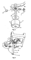
- FIG. 2a Shown in Figure 2a is the cylindrical holder 13 for and with the collimator 2.
- the holder 13 has on its circumference a thread segment 14, which is substantially formed in an angular range of 180°.
- a lug 15 into which an engagement bore 16 for an adjusting tool has been introduced is formed onto the holder 13 coaxially and axially parallel.
- a receptacle 17, shown in Figure 3 arranged coaxially in relation to the axis Z on the base block 1 is a receptacle 17, shown in Figure 3 , with a hollow-cylindrical bearing surface 18, the inside diameter of which corresponds to the outside diameter of the holder 13.
- a groove 19, which corresponds in form and cross section to the thread segment 14, and the fixing hole 12 have been introduced into the wall of the receptacle 17, in the region of the bearing surface 18.
- FIG. 2b Shown in Figure 2b is the collimator holder 13 positioned in the receptacle 17, said holder bearing against the bearing surface 18 in the region of the thread segment 14 and thereby engaging positively with its thread segment 14 in the groove 19.
- the lug 15 is arranged substantially parallel to the bottom of the base block 1 and in the region of the opening 9, so that the engagement bore 16 is accessible through this opening 9.
- Figure 2c illustrates the arrangement in the view from the underside of the base block 1.
- an adjusting rod 20 ( Figure 6 ) is inserted through the opening 9, formed as a slot transversely in relation to the axis Z, into the engagement bore 16.
- This rod (20) has an elongate gripping shank 21 and, arranged on its end face on the base block side, an insert pin 22 for the engagement bore 16, the outside diameter of which is adapted to the inside diameter of said bore.
- FIGs 4a and b Shown in Figures 4a and b as well as 5 are the formation and arrangement of the cylindrical DVD-grating holder (holder) 23 provided with the DVD grating 4 and also the setting of the same with an adjusting tool 24.
- the holder 23 is prepositioned along the optical axis Z in one of two axially parallel bearing surfaces 25 and 26 arranged at right angles to each other and is thereby pressed by the leaf spring 6, represented in Figure 1 , against these bearing surfaces 25 and 26.
- Formed in the holder 23 is an engagement opening 27 for the adjusting tool 24, which during the prepositioning of the holder 23 comes into such an arrangement that it is accessible through the slot opening 10 on the underside of the base block 1 ( Figure 1 ).
- the slot opening 10 is formed transversely in relation to the axis Z and offset in the direction of the holder 23, the bearing surface 28 formed by the offset being curved coaxially in relation to the axis Z and the slot surfaces 29 and 30 arranged substantially perpendicularly in relation to the base area of the base body being guiding surfaces for the adjusting tool 24.
- the adjusting tool 24 ( Figure 5 ) has an elongate shank with a grip 31, formed on which there are, on the base block side an annular shoulder 32, formed by an offset, for bearing against the bearing surface 28 and, on the end face, an eccentrically arranged insert pin 33 for the engagement opening 27, the diameter of the insert pin 33 corresponding to that of the insertion opening 27 and the diameter of the offset gripping shank corresponding to the respective slot surfaces 29 and 30 ( Figure 4b ).
- this adjusting tool 24 is inserted with the insert pin 33 through the slot opening 10 into the engagement opening 27 and is then located with said pin (33) substantially over its (33) entire length in positive engagement with the insertion opening (27) when the shoulder 32 bears against the bearing surface 28, and is laterally guided transversely in relation to the axis Z by the slot surfaces 29 and 30.
- a rotational movement of the adjusting tool 24 about the shank axis initiates through the eccentrically arranged insert pin 33 an adjusting movement of the holder 23 in the direction of the axis Z and a pivoting movement transversely in relation to the axis Z initiates a rotational movement of the holder 23 about the said axis.
- an adhesive is introduced into the slot opening 10 after removal of the adjusting tool 24 and the holder 23 is fixed by said adhesive.
Landscapes
- Physics & Mathematics (AREA)
- Optics & Photonics (AREA)
- Optical Head (AREA)
- Moving Of The Head For Recording And Reproducing By Optical Means (AREA)
- Mechanical Optical Scanning Systems (AREA)
- Facsimile Scanning Arrangements (AREA)
- Mounting And Adjusting Of Optical Elements (AREA)
Applications Claiming Priority (2)
| Application Number | Priority Date | Filing Date | Title |
|---|---|---|---|
| DE10344504 | 2003-09-24 | ||
| DE10344504A DE10344504A1 (de) | 2003-09-24 | 2003-09-24 | Abtasteinrichtung für ein Gerät zum Lesen oder Beschreiben optischer Aufzeichnungsträger |
Publications (3)
| Publication Number | Publication Date |
|---|---|
| EP1521249A2 EP1521249A2 (en) | 2005-04-06 |
| EP1521249A3 EP1521249A3 (en) | 2007-08-29 |
| EP1521249B1 true EP1521249B1 (en) | 2009-09-02 |
Family
ID=34306067
Family Applications (1)
| Application Number | Title | Priority Date | Filing Date |
|---|---|---|---|
| EP04300400A Expired - Lifetime EP1521249B1 (en) | 2003-09-24 | 2004-06-28 | Scanning device for an apparatus for reading from or writing to optical recording media |
Country Status (7)
| Country | Link |
|---|---|
| US (1) | US7484230B2 (ja) |
| EP (1) | EP1521249B1 (ja) |
| JP (1) | JP2005100613A (ja) |
| KR (1) | KR20050030119A (ja) |
| CN (1) | CN100412964C (ja) |
| DE (2) | DE10344504A1 (ja) |
| TW (1) | TW200512747A (ja) |
Families Citing this family (1)
| Publication number | Priority date | Publication date | Assignee | Title |
|---|---|---|---|---|
| JP7336996B2 (ja) * | 2020-01-10 | 2023-09-01 | 三菱電機株式会社 | 偏心調整装置 |
Family Cites Families (30)
| Publication number | Priority date | Publication date | Assignee | Title |
|---|---|---|---|---|
| DE1778808U (de) * | 1958-09-27 | 1958-12-04 | Carl Braun Camerawerk | Projektor, insbesondere dia-projektor. |
| DE1812867U (de) * | 1960-02-08 | 1960-06-09 | Wesegang Fa Ed | Vorrichtung zur objektivverstellung bei fernsteuerbaren projektionskameras. |
| US3489026A (en) | 1967-12-18 | 1970-01-13 | John C Bond | Worm gear mechanism |
| DE1778808A1 (de) | 1968-06-07 | 1971-08-05 | Hermann Berstorff Maschb Gmbh | Verfahren zur Herstellung von Bahnen aus Gummi oder Kunststoffen und Einrichtung zur Durchfuehrung dieses Verfahrens |
| GB2060927B (en) * | 1979-07-24 | 1984-02-01 | Universal Pioneer Corp | Signal reading device for optical discs |
| JPH0196612A (ja) * | 1987-10-08 | 1989-04-14 | Minolta Camera Co Ltd | アナモフィック光学素子保持装置 |
| DE3800428A1 (de) * | 1988-01-09 | 1989-07-20 | Breitmeier Ulrich | Optischer abtastkopf |
| US5146441A (en) * | 1990-05-26 | 1992-09-08 | Pioneer Electronic Corporation | Supporting device of an optical pickup |
| US5287337A (en) * | 1990-05-26 | 1994-02-15 | Pioneer Electronic Corporatioin | Optical pickup having flexible wiring plate with focusing effective length which eliminates plate restoring force induce pickup tilt during focusing |
| JP2893047B2 (ja) * | 1990-07-02 | 1999-05-17 | 日本電信電話株式会社 | 光ファイバ余長処理モジュール |
| US5237457A (en) * | 1990-10-04 | 1993-08-17 | Asahi Kogaku Kogyo Kabushiki Kaisha | Apparatus for adjusting an optical axis including a laser beam source and a beam shaping prism |
| JP2984526B2 (ja) * | 1993-08-31 | 1999-11-29 | 日本電気株式会社 | 光ピックアップ装置 |
| JP3606598B2 (ja) * | 1994-03-22 | 2005-01-05 | 富士写真フイルム株式会社 | レンズ付きフィルムユニットのピント調整方法及びその機構 |
| JPH08149347A (ja) * | 1994-11-21 | 1996-06-07 | Matsushita Electric Ind Co Ltd | 画像表示装置付ビデオカメラ用ファインダー |
| KR0137245B1 (ko) * | 1995-05-31 | 1998-05-15 | 배순훈 | 듀얼포커스법에 사용되는 광학헤드 위치 조절장치(an optical head position adjusting device using at the method of dual focus) |
| JP3694154B2 (ja) * | 1997-09-30 | 2005-09-14 | ペンタックス株式会社 | レンズ位置調整固定装置及びレンズ位置調整固定方法 |
| JPH11312316A (ja) * | 1998-04-28 | 1999-11-09 | Sankyo Seiki Mfg Co Ltd | 光ピックアップ装置 |
| JP2000019374A (ja) * | 1998-06-29 | 2000-01-21 | Murata Mfg Co Ltd | フォーカスユニット及び画像形成装置 |
| JP4121213B2 (ja) * | 1998-10-14 | 2008-07-23 | 株式会社リコー | カップリングレンズおよび光ピックアップ |
| DE19860563C2 (de) * | 1998-12-22 | 2001-09-06 | Hertz Inst Heinrich | Optischer Abtastkopf für Datenspeicherplatten |
| US6709114B1 (en) * | 2000-01-27 | 2004-03-23 | Thomson Licensing S.A. | Spherical mounting system for three axis adjustment of light projector assembly in a projection television |
| JP3655530B2 (ja) * | 2000-04-06 | 2005-06-02 | 株式会社三協精機製作所 | 光ヘッド装置 |
| KR100935596B1 (ko) * | 2000-12-22 | 2010-01-07 | 코닌클리케 필립스 일렉트로닉스 엔.브이. | 광학 주사장치와 이 주사장치를 구비한 광학 재생장치 |
| JP2002350701A (ja) * | 2001-05-28 | 2002-12-04 | Sony Corp | 撮像レンズ装置 |
| JP3906045B2 (ja) * | 2001-08-24 | 2007-04-18 | 三洋電機株式会社 | 光学ヘッドにおける回折格子調整装置 |
| JP2003203360A (ja) * | 2001-12-27 | 2003-07-18 | Sankyo Seiki Mfg Co Ltd | 光ヘッド装置およびその製造方法 |
| JP3759046B2 (ja) * | 2002-01-29 | 2006-03-22 | ミツミ電機株式会社 | 光学ピックアップ装置用レンズホルダ |
| JP3881582B2 (ja) * | 2002-04-22 | 2007-02-14 | ペンタックス株式会社 | Cctvカメラ用レンズ鏡筒の操作リング固定装置 |
| JP4299778B2 (ja) * | 2002-05-31 | 2009-07-22 | パナソニック株式会社 | レンズ支持機構、光ヘッド装置および光情報処理装置 |
| JP2004240140A (ja) * | 2003-02-05 | 2004-08-26 | Olympus Corp | 光学素子保持機構 |
-
2003
- 2003-09-24 DE DE10344504A patent/DE10344504A1/de not_active Withdrawn
-
2004
- 2004-06-28 EP EP04300400A patent/EP1521249B1/en not_active Expired - Lifetime
- 2004-06-28 DE DE602004022904T patent/DE602004022904D1/de not_active Expired - Fee Related
- 2004-09-10 TW TW093127355A patent/TW200512747A/zh unknown
- 2004-09-15 CN CNB2004100785821A patent/CN100412964C/zh not_active Expired - Fee Related
- 2004-09-21 US US10/947,025 patent/US7484230B2/en not_active Expired - Fee Related
- 2004-09-22 KR KR1020040075775A patent/KR20050030119A/ko not_active Withdrawn
- 2004-09-22 JP JP2004275084A patent/JP2005100613A/ja not_active Ceased
Also Published As
| Publication number | Publication date |
|---|---|
| EP1521249A3 (en) | 2007-08-29 |
| US7484230B2 (en) | 2009-01-27 |
| DE10344504A1 (de) | 2005-05-25 |
| KR20050030119A (ko) | 2005-03-29 |
| TW200512747A (en) | 2005-04-01 |
| DE602004022904D1 (de) | 2009-10-15 |
| CN1601626A (zh) | 2005-03-30 |
| EP1521249A2 (en) | 2005-04-06 |
| US20050066347A1 (en) | 2005-03-24 |
| JP2005100613A (ja) | 2005-04-14 |
| CN100412964C (zh) | 2008-08-20 |
Similar Documents
| Publication | Publication Date | Title |
|---|---|---|
| US6567362B1 (en) | Optical disk device having guide shaft for guiding optical pickup | |
| US5488594A (en) | Objective actuator for positioning an optical pick-up device | |
| US5889755A (en) | Pickup adjusting apparatus of an optical disk player | |
| US5796707A (en) | Optical recording and reproducing apparatus having means for correcting installation angle of spindle motor | |
| US7484230B2 (en) | Scanning device for an apparatus for reading from or writing to optical recording media | |
| JP4918061B2 (ja) | レンズ駆動装置及び電子機器 | |
| US7370340B2 (en) | Recording and/or reproduction apparatus for optical recording media with means for parallel orientation of the scanning device with respect to the surface of the recording medium | |
| EP1701343B1 (en) | Scanning device for optical storage media | |
| JP4143424B2 (ja) | 光ディスク装置 | |
| JP3694154B2 (ja) | レンズ位置調整固定装置及びレンズ位置調整固定方法 | |
| US20050276182A1 (en) | Disk unit | |
| US20100058370A1 (en) | Optical pickup guide device, method for manufacturing the same, and disc device | |
| US8151287B2 (en) | Optical pickup feed device for sliding optical pickup | |
| JP3809705B2 (ja) | 光ピックアップ送り機構、光ピックアップ送り機構における案内レール取り付け方法及びその案内レール取り付け治具 | |
| KR100289720B1 (ko) | 광픽업이송장치 | |
| JP2001222823A (ja) | ディスクドライブ装置及びスキュー調整部材 | |
| KR910005213Y1 (ko) | 디스크형 기록매체 재생장치의 픽업 이송나사 착설기구 | |
| US20090210891A1 (en) | Optical disk device and adjusting method thereof | |
| KR0176592B1 (ko) | 광 기록 재생 장치 | |
| US20070204282A1 (en) | Optical Scanning Apparatus For Various Appliances For Recording Or Reproducing Data Or Information Using An Optical Recording Medium | |
| KR19980015587U (ko) | 디스크 플레이어의 광픽업 유니트 이송장치 | |
| JP2002133757A (ja) | 光ディスク再生装置 | |
| KR20030073762A (ko) | 디스크 드라이브의 틸트 조정장치 | |
| JPS5982642A (ja) | レンズ組込調整装置 | |
| KR20010055857A (ko) | 디스크 드라이버의 픽업 이동안내장치 |
Legal Events
| Date | Code | Title | Description |
|---|---|---|---|
| PUAI | Public reference made under article 153(3) epc to a published international application that has entered the european phase |
Free format text: ORIGINAL CODE: 0009012 |
|
| AK | Designated contracting states |
Kind code of ref document: A2 Designated state(s): AT BE BG CH CY CZ DE DK EE ES FI FR GB GR HU IE IT LI LU MC NL PL PT RO SE SI SK TR |
|
| AX | Request for extension of the european patent |
Extension state: AL HR LT LV MK |
|
| RAP1 | Party data changed (applicant data changed or rights of an application transferred) |
Owner name: THOMSON LICENSING |
|
| PUAL | Search report despatched |
Free format text: ORIGINAL CODE: 0009013 |
|
| AK | Designated contracting states |
Kind code of ref document: A3 Designated state(s): AT BE BG CH CY CZ DE DK EE ES FI FR GB GR HU IE IT LI LU MC NL PL PT RO SE SI SK TR |
|
| AX | Request for extension of the european patent |
Extension state: AL HR LT LV MK |
|
| 17P | Request for examination filed |
Effective date: 20080218 |
|
| AKX | Designation fees paid |
Designated state(s): DE FR GB |
|
| 17Q | First examination report despatched |
Effective date: 20080424 |
|
| GRAP | Despatch of communication of intention to grant a patent |
Free format text: ORIGINAL CODE: EPIDOSNIGR1 |
|
| GRAS | Grant fee paid |
Free format text: ORIGINAL CODE: EPIDOSNIGR3 |
|
| GRAA | (expected) grant |
Free format text: ORIGINAL CODE: 0009210 |
|
| AK | Designated contracting states |
Kind code of ref document: B1 Designated state(s): DE FR GB |
|
| REF | Corresponds to: |
Ref document number: 602004022904 Country of ref document: DE Date of ref document: 20091015 Kind code of ref document: P |
|
| REG | Reference to a national code |
Ref country code: GB Ref legal event code: 746 Effective date: 20091012 |
|
| RAP2 | Party data changed (patent owner data changed or rights of a patent transferred) |
Owner name: THOMSON LICENSING |
|
| PLBE | No opposition filed within time limit |
Free format text: ORIGINAL CODE: 0009261 |
|
| STAA | Information on the status of an ep patent application or granted ep patent |
Free format text: STATUS: NO OPPOSITION FILED WITHIN TIME LIMIT |
|
| 26N | No opposition filed |
Effective date: 20100603 |
|
| GBPC | Gb: european patent ceased through non-payment of renewal fee |
Effective date: 20100628 |
|
| REG | Reference to a national code |
Ref country code: FR Ref legal event code: ST Effective date: 20110228 |
|
| PG25 | Lapsed in a contracting state [announced via postgrant information from national office to epo] |
Ref country code: DE Free format text: LAPSE BECAUSE OF NON-PAYMENT OF DUE FEES Effective date: 20110101 |
|
| PG25 | Lapsed in a contracting state [announced via postgrant information from national office to epo] |
Ref country code: FR Free format text: LAPSE BECAUSE OF NON-PAYMENT OF DUE FEES Effective date: 20100630 |
|
| PG25 | Lapsed in a contracting state [announced via postgrant information from national office to epo] |
Ref country code: GB Free format text: LAPSE BECAUSE OF NON-PAYMENT OF DUE FEES Effective date: 20100628 |