EP1509039B1 - Kamera - Google Patents
Kamera Download PDFInfo
- Publication number
- EP1509039B1 EP1509039B1 EP04103874A EP04103874A EP1509039B1 EP 1509039 B1 EP1509039 B1 EP 1509039B1 EP 04103874 A EP04103874 A EP 04103874A EP 04103874 A EP04103874 A EP 04103874A EP 1509039 B1 EP1509039 B1 EP 1509039B1
- Authority
- EP
- European Patent Office
- Prior art keywords
- image
- display panel
- bracket
- axis
- photographing apparatus
- Prior art date
- Legal status (The legal status is an assumption and is not a legal conclusion. Google has not performed a legal analysis and makes no representation as to the accuracy of the status listed.)
- Expired - Lifetime
Links
Images


Classifications
-
- H—ELECTRICITY
- H01—ELECTRIC ELEMENTS
- H01H—ELECTRIC SWITCHES; RELAYS; SELECTORS; EMERGENCY PROTECTIVE DEVICES
- H01H19/00—Switches operated by an operating part which is rotatable about a longitudinal axis thereof and which is acted upon directly by a solid body external to the switch, e.g. by a hand
- H01H19/54—Switches operated by an operating part which is rotatable about a longitudinal axis thereof and which is acted upon directly by a solid body external to the switch, e.g. by a hand the operating part having at least five or an unspecified number of operative positions
- H01H19/56—Angularly-movable actuating part carrying contacts, e.g. drum switch
- H01H19/58—Angularly-movable actuating part carrying contacts, e.g. drum switch having only axial contact pressure, e.g. disc switch, wafer switch
- H01H19/585—Angularly-movable actuating part carrying contacts, e.g. drum switch having only axial contact pressure, e.g. disc switch, wafer switch provided with printed circuit contacts
-
- H—ELECTRICITY
- H04—ELECTRIC COMMUNICATION TECHNIQUE
- H04N—PICTORIAL COMMUNICATION, e.g. TELEVISION
- H04N23/00—Cameras or camera modules comprising electronic image sensors; Control thereof
-
- H—ELECTRICITY
- H04—ELECTRIC COMMUNICATION TECHNIQUE
- H04N—PICTORIAL COMMUNICATION, e.g. TELEVISION
- H04N23/00—Cameras or camera modules comprising electronic image sensors; Control thereof
- H04N23/50—Constructional details
- H04N23/53—Constructional details of electronic viewfinders, e.g. rotatable or detachable
- H04N23/531—Constructional details of electronic viewfinders, e.g. rotatable or detachable being rotatable or detachable
-
- H—ELECTRICITY
- H04—ELECTRIC COMMUNICATION TECHNIQUE
- H04N—PICTORIAL COMMUNICATION, e.g. TELEVISION
- H04N23/00—Cameras or camera modules comprising electronic image sensors; Control thereof
- H04N23/60—Control of cameras or camera modules
- H04N23/63—Control of cameras or camera modules by using electronic viewfinders
Definitions
- the present invention relates to a camera, comprising a handheld component.
- An image photographing apparatus for example, a camcorder
- a camcorder is a known device allowing the recording and playback of primarily moving images, usually onto a magnetic tape.
- the camcorder includes a lens for capturing the image, a recording and reproducing device for recording and reproducing the captured image and a display device for displaying the recorded images.
- the known recording and reproducing device uses a deck with a magnetic tape.
- recent developments in recording and reproducing devices allow the use of other storage devices such as memory sticks, as well as other developments such as high-capacity High Definition Displays (HDD). These developments have enabled the reduction in size and weight of the camcorder.
- HDD High Definition Displays
- Display devices generally include a Liquid Crystal Display (LCD) panel mounted to a side of a body of the camcorder.
- the LCD can be opened and closed.
- the LCD also includes a viewfinder.
- the LCD panel is placed on the left side of the camcorder body from a point of view of the operator.
- the LCD panel is disposed at the left side to avoid interfering with the user's right hand. Accordingly, the LCD panel is opened and closed at the beginning and end of a recording, and the LCD panel turns by a predetermined angle when opened.
- the viewfinder is disposed at the opposite side to the lens.
- the LCD panel is designed for the right-handed user and is disposed at the left side of the camcorder, the LCD panel is inconvenient for the left-handed user to operate. Also, even if the operator is a right-handed user, the operator sometimes wants to hold the camcorder using their left hand. In this situation, the operator is inconvenienced.
- the present invention has been developed in order to solve the above described problems in the prior art. Accordingly, it is an aspect of the present invention to provide an image-photographing apparatus having an improved structure and method, which is capable of selectively changing a position of a display panel to suit both the right-handed operator and left-handed operator.
- the present invention relates to a camera, comprising a handheld component.
- JP 06 169418 disclosed a video camera in which a monitor is rotated between a left side of a body and a right side of the body.
- JP 2001 358973 discloses a video camera in which a connection mechanism is rotated for rotating a display panel.
- WO 03/042851 discloses a hand held device such as a digital camera having a rotatable display panel.
- the invention provides an image-photographing apparatus comprising: a camera unit for capturing an image; a body in which the camera unit is disposed; a display panel for displaying the image; and a hinge unit connected to the display panel, for rotating the display panel between one side of the body and the other side of the body about a first axis and rotating the display panel about a second axis perpendicular to the first axis, wherein the hinge unit comprises a fixing bracket fixed to the body and having a shaft hole; a shaft member inserted into the shaft hole; and a rotary bracket supported on the shaft member to be rotatable with respect to the fixing bracket.
- the image-photographing apparatus according to the invention is defined in claim 1 .
- an image photographing apparatus (or camera) according to an embodiment of the present invention includes a body 10, and a display panel 20 movably disposed to the body 10.
- the body 10 has a first case 11 in which a deck and a circuit board 10b are mounted, and a second case 12 and a third case 13 disposed above the first case 11.
- the second case 12 and the third case 13 are connected together and are flush with one another.
- the second and the third cases 12 and 13 are lens barrel type cases, and with predetermined gap G provided therebetween.
- a lens unit 14 is disposed in the second case 12 to capture an image, and a viewfinder unit 15 is disposed in the third case 13.
- the first case 11 has a panel receiving portion 11a located in one side thereof.
- a battery receiving portion (not shown) is located in the other side of the first case 11, opposite the panel receiving portion 11a (see Figure 1 ).
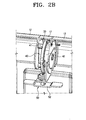
- a cover bracket 17 is connected to a hinge unit 30.
- the cover bracket 17 is connected to a rotary bracket 42 (see Figure 2B ), which will be described in detail later, so that the cover bracket 17 is rotated with the rotary bracket 42 whilst covering the gap G.
- the display panel 20 is connected to the body 10 by the hinge unit 30 so that the display panel 20 is movable to the right and left sides of the body 10 and, more specifically, the first case 11.
- the display panel 20 is configured such that it rotates about two axes, enabling the display panel 20 to rotate about an image-photographing direction 'A' and a predetermined axial direction 'B' which is perpendicular to direction 'A'.
- the hinge unit 30 includes a first axis unit 40 for turning the display panel 20 about the image-photographing direction 'A', and a second axis unit 50 connected to the first axis unit 40, for turning the display panel 20 about the axial direction 'B'.
- the first axis unit 40 includes a fixing bracket 41, a rotary bracket 42, a shaft member, a click bracket 44, and a fixing member 45.
- the fixing bracket 41 is fixed to an upper end of the body 10 and specifically, to a surface of the second case 12 which faces the third case 13.
- the fixing bracket 41 has a shaft hole 41a into which the shaft member 43 is inserted.
- a surface of the fixing bracket 41, which faces the third case 13, has a plurality of click recesses 41b and at least one protrusion 41c.
- the click recesses 41b are formed at a predetermined interval relative to the shaft hole 41 a.
- the rotary bracket 42 has a shaft hole 42a (see Figure 4 ) into which the shaft member 43 is inserted, and which supports the second axis unit 50.
- the rotary bracket 42 rotates about the shaft member 43 with the shaft member 42 being inserted into the shaft hole 42a.
- the rotary bracket 42 rotates in the image-photographing direction 'A', and accordingly, the display panel 20 rotates by a predetermined angle in the image-photographing direction 'A'.
- the rotary bracket 42 has a protrusion 42b protruding from a surface facing the fixing bracket 41. The protrusion 42b secures the click bracket 44.
- the rotary bracket 42 is provided with a receiving recess 42c depressed therein, for receiving and supporting a switching elastic piece 63, which will be described later. Also, a supporting portion 42d extends from one side of the rotary bracket 42 in a curve to support the second axis unit 50.
- the click bracket 44 is located between the fixing bracket 41 and the rotary bracket 42.
- the click bracket 44 is a ring-type plate spring and has a plurality of embossed portions 44a at predetermined intervals, corresponding to the click recesses 41b.
- the click bracket 44 has position fixing holes 44b corresponding to the protrusions 42b of the rotary bracket 42. As the protrusions 42b fit into the holes 44b, the click bracket 44 is fixed to the rotary bracket 42. This means that the embossed portions 44a of the click bracket 44 are inserted into and separated from the click recesses 41 b as the rotary bracket 42 is rotated. Accordingly, a click occurs at a predetermined angle.
- the fixing bracket 41, the rotary bracket 42 and the click bracket 44 are tightly assembled with one another, without any separations.
- the first axis unit 40 further includes a sensing switch 60 to detect rotation of the display panel 20, 10 and specifically, the position of the display panel when the display panel 20 rotates in the image-photographing direction 'A'.
- the sensing switch 60 includes a pattern terminal panel 61 supported on the fixing bracket 41 and the switching elastic piece 63 is placed on the rotary bracket 42 such that the switching elastic piece 63 faces, and makes contact with, the pattern terminal panel 61.
- the switching elastic piece 63 has preferably metallic contacts and is formed such that it remains in contact with the pattern terminal panel 61.
- the pattern terminal panel 61 is a disk-type plate having a hollow space 61 a formed in a centre thereof, through which the shaft member 43 passes.
- the pattern terminal panel 61 has a connection hole 61b which engages with the protrusion 41c of the fixing bracket 41.
- the pattern terminal panel 61 may be secured to the fixing bracket 41 by an adhesive.
- the switching terminal unit 62 On the surface of the pattern terminal panel 61 facing the rotary bracket 42, is formed a switching terminal unit 62.
- the switching terminal unit 62 contains a number of electrical conductors formed in a predetermined pattern. These conductors are electrically connected to the switching elastic piece 63.
- the switching terminal unit 62 includes a common terminal 62a formed around the hollow 61a in a predetermined circular pattern, and a first, a second, and a third mode terminal 62b, 62c, and 62d formed around the common terminal 62a in respective predetermined patterns.
- the common terminal 62a maintains contact with the switching elastic piece 63.
- the sensing switch 60 detects a rotation angle of the rotary bracket 42 by detecting which mode terminal from amongst the first, second, and third mode terminals 62b, 62c and 62d are connected to the switching elastic piece 63 at any one time. Based on the information about the rotation angle, the sensing switch 60 detects the amount of rotation undergone by the display panel 20 and determines coordinates of the displayed image. For this, the respective first, second and third mode terminals 62b, 62c, and 62d extend around a predetermined fraction of the switching terminals unit 62.
- each of the first, second and third mode terminals 62b, 62c and 62d extend over a predetermined angle of the switching terminal unit 62, without overlapping. It is also possible that the common terminal 62a forms a ring shape outside the first, the second and the third mode terminals 62b, 62c, and 62d.
- the first, the second, and the third mode terminals 62b, 62c, and 62d are each formed at a predetermined angular distance from a reference angle 0°.
- the reference angle 0° is determined when the first mode terminal 62b contacts with the switching elastic piece 63 when the display panel 20 is mounted in the panel receiving portion 11a of the body 10.
- the first mode terminal 62b is continuously formed within a range from azimuth 0 ° to, at least, 135°. More specifically, the first mode terminal 62b extends from 0° to a predetermined distance between 135° to 180°.
- the second mode terminal 62c extends to a predetermined distance within a range from 125° to 225° from 0°
- the third mode terminal 62d is formed within a range from 225° to 270° from 0°.
- the respective mode terminals 62b, 62c, and 62d are concentrically positioned, but occupy spaces of different azimuth angles. In other words, the first, second and third mode terminals 62b, 62c and 62d do not overlap with one another.
- the first and the second mode terminals 62b and 62c are separated from each other at a position somewhere between 135° and 180° from 0°, and the second and the third mode terminals 62c and 62d are separated from each other at a position between 180° and 225° from 0°.
- the respective mode terminals 62b, 62c, and 62d are connected to a controller (not shown) to provide information about which mode terminal is contacting with the switching elastic piece 63. Based on the provided information, the controller selectively rotates the image coordinates displayed on the display panel 20 by at most 90° with respect to the previous mode and displays the rotated image coordinates.
- the switching elastic piece 63 is fixed into the receiving recess 42c of the fixing bracket 42.
- the switching elastic piece 63 has a first contact piece 63a in contact with the basic terminal 62a at all times, and a second contact piece 63b adjacent to the first contact piece 63a and which contacts with one of the mode terminals 62b, 62c and 63d.
- the first and the second contact pieces 63a and 63b are provided in pairs, each of which being formed by cutting, to thereby prevent deformations and to improve the contact.
- the switching elastic piece 63 and the pattern terminal panel 61 are exchangeable in their position. In other words, the switching elastic means 63 can rotate and the pattern terminal panel 61 can remain fixed.
- the second axis unit 50 is connected to the supporting portion 42d of the rotary bracket 42 to support and rotate the display panel 20 with respect to the axial direction 'B'.
- the second axis unit 50 employs a conventional hinge construction, it includes a shaft 51 rotatably inserted into a shaft hole h1 of the supporting portion 42d, a panel supporting bracket 52 connected to a lower end of the shaft 51 inserted into the supporting portion 42d, a locking bracket 53 fixed to the supporting portion 42d and allows the shaft 51 to rotatably pass therethrough, a plate spring type elastic bracket 54, a rotation angle regulating member 55 and a fixing member 56 for preventing separation.
- the supporting bracket 53 is connected to the display panel 20. Accordingly, the rotation of the supporting bracket 53 with respect to the shaft 51 and with respect to the rotary bracket 42 all occur within the display panel 20.
- the locking bracket 53 is fixed to an upper surface of the supporting portion 42d together with the elastic (movable) bracket 54.
- the fixing bracket 54 has a pair of fixing hooks 54b, and the fixing hooks 54b pass through a pair of passing holes 53b formed in the locking bracket 53.
- the fixing hooks 54b are inserted into locking holes h2 formed in the supporting portion 42d.
- the locking bracket 53 and the elastic bracket 54 have shaft holes 53a, 54a, respectively, through which the shaft 52 is rotatably inserted.
- the regulating member 55 has a non-circular connection hole 55a to which the shaft 51 is connected. This means that the regulating member 55 is connected to the shaft whilst being in contact with the elastic bracket 54. The regulating member 55 thus rotates with the shaft 51.
- a pair of latching portions 55b are located that latch onto a regulating protrusion 53c as the regulating member 55 rotates. Since the regulating member 55 rotates whilst being in contact with the regulating protrusion 53c, the regulating member 55 is subject to less friction during the rotation, and also noise can be reduced.
- the fixing member 56 is connected to a top end of the shaft 51 to prevent the members 53, 54, and 55 from being separated from the shaft 51.
- Figure 6 shows the situation where the display panel 20 is located in the body 10 prior to being opened.
- the switching elastic piece 63 is positioned at the reference angle 0° as shown in Figure 5 , and the common terminal 62a is electrically connected to the first mode terminal 62b.
- Figure 7A shows the display panel 20 when rotated 90° in direction A by the first axis unit 40 and also rotated 90° in predetermined axial direction B by the second axis unit 50.
- the rotary bracket 42 is rotated by 90°. Accordingly, the switching elastic piece 63 supported on the rotary bracket 42 is positioned at a distance, rotated relative to the reference angle (0°) by as much as 90°. This is shown in Figure 7B .
- the switching elastic piece 63 is connected to the common terminal 62a and the first mode terminal 62b. Accordingly, the image on the display panel 20 has an upper image and a lower image extending along the 'y' axis. Also, in this situation the display panel 20 is positioned at the left side of the body 10 and is thus convenient for a right-handed person.
- Figure 8B shows a situation where the display panel 20 is further rotated, in an anti-clockwise direction, 45° from the situation as shown in Figure 7A .
- the switching elastic piece 63 is still contacting the common terminal 62a and the first mode terminal 62b as shown in Figure 8A .
- the controller controls the image to be displayed on the display panel 20 with an upper image and a lower image extending along the 'y' axis.
- the display panel 20 shows the image that appears at 90°. This means that, as the display panel 20 has rotated in an anticlockwise direction and because the image has not been manipulated, a tilted image, relative to the camcorder, is displayed. The image will tilt between 0° and, at least, 135° from the reference.
- the switching elastic piece 63 When the switching elastic piece 63 is moved toward 180° after passing 135°, the switching elastic piece 63 loses contact with the first mode terminal 62b and comes into contact with the second mode terminal 62c.
- the image displayed on the display panel 20 is manipulated and switched by 90°.
- FIG. 9B when the display panel 20 is rotated by 180° from the initial position, the image displayed thereon is rotated and appears with the upper image and the lower image extending along the 'x' axis.
- the switching elastic piece 63 is electrically connected to the common terminal 62a and the second mode terminal 62c as shown in Figure 9A .
- the switching elastic piece 63 loses contact with the second mode terminal 62c and contacts with the third mode terminal 62d. Accordingly, the image displayed on the display panel 20 is rotated from the situation in Figure 9B by 90°. In other words, the image appears with an upper image and a lower image extending along the 'y' axis. It should be noted that in the third mode, the image is rotated by 180° from the original orientation of the image.
- the display panel 20 can rotate further from the situation shown in Figure 10B by 45°.
- the switching elastic piece 63 maintains contact with the third mode terminal 62d, and the image appears along the 'y' axis.
- the images have switched 180° with regard to the situation shown in Figure 7B .
- the image displayed in Figure 11B is the same image as shown in Figure 7B but the orientation has been switched by 180° so that the displayed image is correctly orientated for the new position of the display.
- the situation illustrated in Figure 11A shows that the display panel 20 is turned to the right side of the body 10 completely. Accordingly, the left-handed person feels no inconvenience in holding the body 10.
- the situation illustrated in Figures 8A to 10B causes no inconvenience to either right-handed or the left-handed people.
- the situation shown in Figures 7A and 7B is suitable for right-handed people, while the situation shown in Figures 11A and 11B is suitable for the left-handed person.
- the orientation of the image displayed on the display panel 20 is determined according to the rotation angle of the display panel 20.
- the construction allows the orientation of the image to be manipulated and even reversed when the display has rotated by a predetermined angle.
- the reversing angle should not be considered as limiting, and can be selected by the operator.
- the image photographing apparatus is designed so that there occurs a click by the click bracket 43 after and before the image is reversed.
- the display panel 20 can be selectively positioned at the right and left sides of the body 10, the operator can use the apparatus with their right or left hand with convenience.
- the image is reversed on predetermined coordinates according to the position of the display panel 20, the operator always can view a normal image during the use of the apparatus.
Landscapes
- Engineering & Computer Science (AREA)
- Multimedia (AREA)
- Signal Processing (AREA)
- Studio Devices (AREA)
- Camera Bodies And Camera Details Or Accessories (AREA)
- Devices For Indicating Variable Information By Combining Individual Elements (AREA)
Claims (14)
- Bildfotografiervorrichtung, die Folgendes umfasst:eine Kameraeinheit zum Aufnehmen eines Bildes;ein Gehäuse (10), in dem die Kameraeinheit angeordnet ist;eine Anzeigetafel (20) zum Anzeigen des Bildes; undeine Gelenkeinheit (30), die mit der Anzeigetafel (20) verbunden ist, um die Anzeigetafel (20) zwischen einer Seite des Gehäuses (10) und der anderen Seite des Gehäuses (10) um eine erste Achse (A) zu drehen und die Anzeigetafel (20) um eine zweite Achse (B) lotrecht zur ersten Achse (A) zu drehen,dadurch gekennzeichnet, dass die Gelenkeinheit (30) Folgendes umfasst: eine an dem Gehäuse (10) befestigte Halterung (41) mit einem Schaftloch (41a); ein in dem Schaftloch (41a) steckendes Schaftelement (43); eine an dem Schaftelement (43) gelagerte Drehhalterung (42), die relativ zur Halterung (41) in Bezug auf eine Bildfotografierrichtung drehbar ist, die von der Kameraeinheit ensprechend der ersten Achse (A) festgelegt wird; und eine zweite Achseneinheit (50), die von der Drehhalterung getragen wird und die Anzeigetafel für eine Drehung um die zweite Achse (B) trägt.
- Bildfotografiervorrichtung nach Anspruch 1, wobei die Halterung (41), das Schaftelement und die Drehhalterung (42) in einer ersten Achseneinheit (40) vorgesehen sind, die die Anzeigetafel (20) in einem Winkel mit Bezug auf die erste Achse (A) entsprechend einer Bildfotografierrichtung trägt und dreht, und die Drehhalterung (42) die mit der ersten Achseneinheit (40) verbundene zweite Achseneinheit (50) trägt und die Anzeigetafel (20) für eine Drehung um die zweite Achse (B) lotrecht zur Bildfotografierrichtung trägt.
- Bildfotografiervorrichtung nach Anspruch 2, wobei die erste Achseneinheit (40) ferner Folgendes umfasst:eine Klickhalterung (44), die zwischen der Halterung (41) und der Drehhalterung (41) angeordnet ist, um einen Klick zu erzeugen, wenn sich die Drehhalterung (41) um einen vorbestimmten Winkel gedreht hat.
- Bildfotografiervorrichtung nach Anspruch 3, wobei die Klickhalterung (44) eine Tellerfeder ist, die an der Drehhalterung (42) befestigt ist und von der erhabene Abschnitte in einem vorbestimmten Drehwinkelintervall vorstehen, die in eine in der Halterung (41) ausgebildete Klickaussparung eingeführt werden.
- Bildfotografiervorrichtung nach Anspruch 2, wobei die erste Achseneinheit (40) ferner einen Erkennungsschalter (60) zum Erkennen eines Drehzustands der Anzeigetafel (20) umfasst.
- Bildfotografiervorrichtung nach Anspruch 5, wobei der Erkennungsschalter (60) Folgendes umfasst:ein Musterabschlussfeld (61), das auf der Halterung (41) liegt und einen Schalteranschluss (62) mit einem vorbestimmten Muster aufweist, das auf einer der Drehhalterung gegenüberliegenden Fläche angeordnet ist; undein elastisches Schaltstück (63), das von der Drehhalterung (42) getragen wird und sich zusammen mit dieser dreht und den Schalteranschluss (62) gemäß einer Drehposition zum Ein- und Ausschalten je nach einem Positionsmodus der Anzeigetafel elastisch kontaktiert.
- Bildfotografiervorrichtung nach Anspruch 6, wobei der Schalteranschluss (62) Folgendes umfasst:einen Basisanschluss (62a), der in einem Kreisbogenmuster um eine Drehachse der Drehhalterung (42) gestaltet ist; undeinen ersten, zweiten und dritten Modusanschluss (62b, 62c und 62d) neben dem Basisanschluss (62a) und durch das elastische Schaltstück (63) gemäß dem Drehwinkel der Drehhalterung (42) selektiv mit dem Referenzanschluss verbunden.
- Bildfotografiervorrichtung nach Anspruch 7, wobei Referenzkoordinaten des auf der Anzeigetafel (20) angezeigten Bildes gemäß Verbindungszuständen des Basisanschlusses (62a) mit den jeweiligen Modusanschlüssen (62b, 62c und 62d) bestimmt werden.
- Bildfotografiervorrichtung nach Anspruch 7, wobei die jeweiligen Modusanschlüsse (62b, 62c und 62d) jeweils einen vorbestimmten Raum zwischen einem Referenzwinkel von 0° und einem Drehwinkel von wenigstens 270° einnehmen, wobei der Referenzwinkel 0 eingestellt wird, wenn die Anzeigetafel (20) im Gehäuse (10) sitzt.
- Bildfotografiervorrichtung nach Anspruch 7, wobei der erste Modusanschluss (62b) in einem Raum zwischen 0° und wenigstens 135° vorgesehen ist, der zweite Modusanschluss (62c) in einem Raum zwischen 135° und 225° vorgesehen ist und der dritte Modusanschluss (62d) in einem Raum zwischen 225° und wenigstens 270° vorgesehen ist und der erste, zweite und dritte Modusanschluss (62b, 62c und 62d) durch das elastische Schaltstück (63) mit dem Basisanschluss (62a) verbunden sind.
- Bildfotografiervorrichtung nach Anspruch 1, wobei das Gehäuse (10) Folgendes umfasst:einen ersten Gehäuseteil (11), in dem ein Speichermedium angeordnet ist;einen mit einem oberen Abschnitt des ersten Gehäuseteils (11) verbundenen zweiten Gehäuseteil (12), in dem die Kameraeinheit angeordnet ist; undeinen dritten Gehäuseteil (13), der mit dem oberen Teil des ersten Gehäuseteils (11) symmetrisch zum zweiten Gehäuseteil (12) verbunden ist, in dem ein Sucher (15) angeordnet ist,wobei zwischen dem zweiten und dem dritten Gehäuseteil (12 und 13) eine Lücke (G) zum beweglichen Aufnehmen der Gelenkeinheit (30) vorgesehen ist.
- Bildfotografiervorrichtung nach Anspruch 11, wobei das Gehäuse (10) ferner eine Abdeckhalterung (17) umfasst, die zum Abdecken der Lücke (G) mit der Gelenkeinheit (30) verbunden ist.
- Bildfotografiervorrichtung nach Anspruch 11, wobei der erste Gehäuseteil (11) Folgendes umfasst:einen Tafelaufnahmeabschnitt (11a), der zum Aufnehmen der Anzeigetafel (20) in einer Außenseite des ersten Gehäuseteils (11) eingelassen ist; undeinen Batterieaufnahmeabschnitt, der in der anderen Außenseite des ersten Gehäuseteils (11) symmetrisch zum Tafelaufnahmeabschnitt (11a) eingelassen ist.
- Bildfotografiervorrichtung nach Anspruch 7, wobei der erste, zweite und dritte Modusanschluss (62b, 62c und 62d) im selben Drehradius angeordnet sind.
Applications Claiming Priority (2)
| Application Number | Priority Date | Filing Date | Title |
|---|---|---|---|
| KR1020030056925A KR100806390B1 (ko) | 2003-08-18 | 2003-08-18 | 영상 촬영장치 |
| KR2003056925 | 2003-08-18 |
Publications (2)
| Publication Number | Publication Date |
|---|---|
| EP1509039A1 EP1509039A1 (de) | 2005-02-23 |
| EP1509039B1 true EP1509039B1 (de) | 2012-10-03 |
Family
ID=34056927
Family Applications (1)
| Application Number | Title | Priority Date | Filing Date |
|---|---|---|---|
| EP04103874A Expired - Lifetime EP1509039B1 (de) | 2003-08-18 | 2004-08-11 | Kamera |
Country Status (5)
| Country | Link |
|---|---|
| US (1) | US7450175B2 (de) |
| EP (1) | EP1509039B1 (de) |
| JP (1) | JP3966863B2 (de) |
| KR (1) | KR100806390B1 (de) |
| CN (1) | CN100476569C (de) |
Families Citing this family (19)
| Publication number | Priority date | Publication date | Assignee | Title |
|---|---|---|---|---|
| JP2006279307A (ja) * | 2005-03-28 | 2006-10-12 | Toshiba Corp | 画像記録再生装置及びキーアサイン変更方法 |
| EP1931132B1 (de) * | 2006-12-04 | 2009-12-09 | Thomson Licensing | Bildschirmhalterung mit Doppelgelenk |
| EP1931131A1 (de) | 2006-12-04 | 2008-06-11 | Thomson Licensing | Doppelscharnieranzeigevorrichtungsaufhängung |
| JP4432982B2 (ja) * | 2007-02-16 | 2010-03-17 | ソニー株式会社 | ビューファインダーおよび撮像装置 |
| JP2009058705A (ja) * | 2007-08-31 | 2009-03-19 | Sanyo Electric Co Ltd | 脚片を設けたカメラ機器 |
| JP2009194735A (ja) * | 2008-02-15 | 2009-08-27 | Sony Corp | 撮像装置 |
| USD640722S1 (en) * | 2008-07-30 | 2011-06-28 | Contour, Inc. | Digital video camera |
| CN101728110A (zh) | 2008-10-30 | 2010-06-09 | 鸿富锦精密工业(深圳)有限公司 | 旋转开关及具有该旋转开关的角度侦测装置 |
| JP2010141743A (ja) * | 2008-12-12 | 2010-06-24 | Sony Corp | 撮像装置 |
| JP4709301B2 (ja) * | 2009-08-06 | 2011-06-22 | キヤノン株式会社 | ビデオカメラ |
| JP5398476B2 (ja) * | 2009-10-29 | 2014-01-29 | キヤノン株式会社 | 撮像装置 |
| JP5388806B2 (ja) * | 2009-11-10 | 2014-01-15 | キヤノン株式会社 | 撮像装置 |
| JP5709501B2 (ja) * | 2010-12-10 | 2015-04-30 | キヤノン株式会社 | 撮像装置 |
| KR101788740B1 (ko) * | 2011-11-15 | 2017-10-20 | 삼성전자주식회사 | 피사체 검출 방법 및 장치와, 디지털 촬영 장치 |
| JP5923759B2 (ja) * | 2012-03-23 | 2016-05-25 | パナソニックIpマネジメント株式会社 | 撮像装置 |
| CN102723068A (zh) * | 2012-05-30 | 2012-10-10 | 厦门华侨电子股份有限公司 | 一种画面随显示屏的转动而自动旋转的方法及其装置 |
| JP6959777B2 (ja) * | 2017-07-12 | 2021-11-05 | 日本電産サンキョー株式会社 | 振れ補正機能付き光学ユニット |
| WO2020050814A1 (en) * | 2018-09-04 | 2020-03-12 | Hewlett-Packard Development Company, L.P. | Hinge switches |
| US11644871B1 (en) * | 2022-02-11 | 2023-05-09 | Dell Products L.P. | Systems and methods for determining hinge angle position in an information handling system |
Citations (2)
| Publication number | Priority date | Publication date | Assignee | Title |
|---|---|---|---|---|
| JPH06169418A (ja) * | 1992-11-30 | 1994-06-14 | Akai Electric Co Ltd | ビデオカメラ |
| JP2001358973A (ja) * | 2000-06-13 | 2001-12-26 | Sony Corp | ビデオカメラ |
Family Cites Families (30)
| Publication number | Priority date | Publication date | Assignee | Title |
|---|---|---|---|---|
| JP2527467Y2 (ja) | 1988-06-01 | 1997-02-26 | 株式会社矢野特殊自動車 | 冷凍冷蔵車の冷凍装置 |
| JPH0511322A (ja) | 1991-07-02 | 1993-01-22 | Canon Inc | カメラの駆動装置 |
| JPH0622186A (ja) | 1992-07-06 | 1994-01-28 | Matsushita Electric Ind Co Ltd | 左右対応ビデオカメラ装置 |
| KR950030599A (ko) | 1994-04-14 | 1995-11-24 | 이헌조 | 캠코더의 액정 뷰파인더 장치 |
| JP3496207B2 (ja) * | 1994-06-22 | 2004-02-09 | ソニー株式会社 | ビデオカメラ |
| JPH08237527A (ja) * | 1995-02-23 | 1996-09-13 | Sony Corp | カメラ一体型ビデオテープレコーダー |
| JP4001958B2 (ja) * | 1996-08-19 | 2007-10-31 | ソニー株式会社 | 撮像装置 |
| JPH10178573A (ja) | 1996-12-17 | 1998-06-30 | Canon Inc | ビデオカメラ |
| US6295088B1 (en) * | 1997-02-17 | 2001-09-25 | Nikon Corporation | Portable display device |
| JP3346213B2 (ja) * | 1997-03-25 | 2002-11-18 | ミノルタ株式会社 | 画像撮影装置 |
| KR100262533B1 (ko) | 1997-12-29 | 2000-08-01 | 윤종용 | 디지털 스틸 카메라 |
| US6683653B1 (en) * | 1998-02-02 | 2004-01-27 | Fuji Photo Film Co., Ltd. | Electronic camera and dial control device of electronic equipment |
| US6459857B2 (en) * | 1998-03-11 | 2002-10-01 | Nikon Corporation | Electronic camera |
| KR200273144Y1 (ko) * | 1998-03-12 | 2002-08-27 | 삼성전자 주식회사 | 캠코더의엘씨디힌지장치 |
| KR19990039933U (ko) * | 1998-04-22 | 1999-11-15 | 유무성 | 디지털 카메라의 뷰파인더 각도 조절장치 |
| JP2001275094A (ja) * | 2000-03-27 | 2001-10-05 | Minolta Co Ltd | 情報通信装置 |
| US6658272B1 (en) * | 2000-04-28 | 2003-12-02 | Motorola, Inc. | Self configuring multiple element portable electronic device |
| JP2002016830A (ja) | 2000-06-28 | 2002-01-18 | Sony Corp | ビデオカメラ |
| US6459856B2 (en) | 2000-07-27 | 2002-10-01 | Asahi Kogaku Kogyo Kabushiki Kaisha | Control dial device of a camera |
| JP4512959B2 (ja) | 2000-08-16 | 2010-07-28 | ソニー株式会社 | 撮像装置 |
| US6912005B2 (en) * | 2001-03-19 | 2005-06-28 | Matsushita Electric Industrial Co., Ltd. | Electronic camera recording/playback apparatus for shooting pictures and editing shot data |
| JP2003046817A (ja) | 2001-07-27 | 2003-02-14 | Sony Corp | 撮像装置 |
| JP2003051970A (ja) * | 2001-08-08 | 2003-02-21 | Sony Corp | 画像記録再生装置 |
| US7359003B1 (en) | 2001-11-09 | 2008-04-15 | Synerdyne Corporation | Display, input and form factor for portable instruments |
| JP4061473B2 (ja) * | 2002-04-26 | 2008-03-19 | 日本電気株式会社 | 折り畳み型携帯電話機 |
| KR100490356B1 (ko) * | 2003-01-20 | 2005-05-17 | 삼성전자주식회사 | 휴대용 무선 단말기의 로터리형 힌지 장치 |
| JP2004254185A (ja) * | 2003-02-21 | 2004-09-09 | Minolta Co Ltd | デジタルカメラ |
| JP3869812B2 (ja) | 2003-03-04 | 2007-01-17 | 三洋電機株式会社 | 電子撮像装置 |
| US6827602B2 (en) | 2003-04-30 | 2004-12-07 | Leviton Manufacturing Co., Inc. | Hospital grade receptacle with power light indicator |
| JP2005006098A (ja) * | 2003-06-12 | 2005-01-06 | Fuji Photo Film Co Ltd | 可動式電子ビューファインダ付デジタルカメラ |
-
2003
- 2003-08-18 KR KR1020030056925A patent/KR100806390B1/ko not_active Expired - Fee Related
-
2004
- 2004-03-31 JP JP2004108013A patent/JP3966863B2/ja not_active Expired - Fee Related
- 2004-08-11 US US10/915,455 patent/US7450175B2/en not_active Expired - Fee Related
- 2004-08-11 EP EP04103874A patent/EP1509039B1/de not_active Expired - Lifetime
- 2004-08-18 CN CNB2004100700804A patent/CN100476569C/zh not_active Expired - Fee Related
Patent Citations (2)
| Publication number | Priority date | Publication date | Assignee | Title |
|---|---|---|---|---|
| JPH06169418A (ja) * | 1992-11-30 | 1994-06-14 | Akai Electric Co Ltd | ビデオカメラ |
| JP2001358973A (ja) * | 2000-06-13 | 2001-12-26 | Sony Corp | ビデオカメラ |
Also Published As
| Publication number | Publication date |
|---|---|
| JP3966863B2 (ja) | 2007-08-29 |
| CN1584726A (zh) | 2005-02-23 |
| KR100806390B1 (ko) | 2008-02-27 |
| US20050041130A1 (en) | 2005-02-24 |
| JP2005065223A (ja) | 2005-03-10 |
| US7450175B2 (en) | 2008-11-11 |
| CN100476569C (zh) | 2009-04-08 |
| EP1509039A1 (de) | 2005-02-23 |
| KR20050019272A (ko) | 2005-03-03 |
Similar Documents
| Publication | Publication Date | Title |
|---|---|---|
| EP1509039B1 (de) | Kamera | |
| JP3496207B2 (ja) | ビデオカメラ | |
| US7907978B2 (en) | Mobile terminal | |
| US20070214604A1 (en) | Portable electronic device having triaxial hinge structure | |
| JP2005176372A (ja) | ディスプレイ位置可変型携帯用端末機及びその作動方法 | |
| EP1710987B1 (de) | Scharniergelenkvorrichtung für ein mobiles Endgerät | |
| JP2003298698A (ja) | 折り畳み式携帯情報端末 | |
| US7576789B2 (en) | Multi-function input switch and photographing apparatus therewith | |
| KR100411921B1 (ko) | 전자모니터를갖는비디오카메라 | |
| US8228057B2 (en) | Swivel portable terminal | |
| JP2006287288A (ja) | 画像記憶装置付カメラ | |
| JP4151272B2 (ja) | 電子機器、ヒンジ装置及び撮像装置 | |
| JP4573077B2 (ja) | 情報処理装置 | |
| US7957629B2 (en) | Image recording/reproducing apparatus | |
| JP3697186B2 (ja) | 設定操作装置およびこれを備えた電子機器 | |
| JP2001197344A (ja) | 被写体を撮影する撮影装置 | |
| JP3697187B2 (ja) | 設定操作装置およびこれを備えた電子機器 | |
| JP2744129B2 (ja) | Vtr一体形カメラ | |
| JP2010054598A (ja) | 撮像装置 | |
| JP2003049823A (ja) | 回転ヒンジ機構及び電子機器 | |
| JP2858344B2 (ja) | ビデオカメラ装置 | |
| JP2007177891A (ja) | モニタ用ヒンジ機構 | |
| JPH10177828A (ja) | 電子機器 | |
| KR100737863B1 (ko) | 전자기기 | |
| JP5217910B2 (ja) | 携帯端末装置 |
Legal Events
| Date | Code | Title | Description |
|---|---|---|---|
| PUAI | Public reference made under article 153(3) epc to a published international application that has entered the european phase |
Free format text: ORIGINAL CODE: 0009012 |
|
| AK | Designated contracting states |
Kind code of ref document: A1 Designated state(s): AT BE BG CH CY CZ DE DK EE ES FI FR GB GR HU IE IT LI LU MC NL PL PT RO SE SI SK TR |
|
| AX | Request for extension of the european patent |
Extension state: AL HR LT LV MK |
|
| 17P | Request for examination filed |
Effective date: 20050609 |
|
| AKX | Designation fees paid |
Designated state(s): DE GB IT NL |
|
| 17Q | First examination report despatched |
Effective date: 20070424 |
|
| REG | Reference to a national code |
Ref country code: DE Ref legal event code: R079 Ref document number: 602004039515 Country of ref document: DE Free format text: PREVIOUS MAIN CLASS: H04N0005232000 Ipc: H04N0005225000 |
|
| RIC1 | Information provided on ipc code assigned before grant |
Ipc: H04N 5/225 20060101AFI20120221BHEP Ipc: H04N 5/232 20060101ALI20120221BHEP Ipc: H01H 19/58 20060101ALI20120221BHEP |
|
| GRAP | Despatch of communication of intention to grant a patent |
Free format text: ORIGINAL CODE: EPIDOSNIGR1 |
|
| GRAS | Grant fee paid |
Free format text: ORIGINAL CODE: EPIDOSNIGR3 |
|
| GRAA | (expected) grant |
Free format text: ORIGINAL CODE: 0009210 |
|
| RAP1 | Party data changed (applicant data changed or rights of an application transferred) |
Owner name: SAMSUNG ELECTRONICS CO., LTD. |
|
| AK | Designated contracting states |
Kind code of ref document: B1 Designated state(s): DE GB IT NL |
|
| REG | Reference to a national code |
Ref country code: GB Ref legal event code: FG4D |
|
| REG | Reference to a national code |
Ref country code: DE Ref legal event code: R096 Ref document number: 602004039515 Country of ref document: DE Effective date: 20121129 |
|
| REG | Reference to a national code |
Ref country code: NL Ref legal event code: T3 |
|
| PLBE | No opposition filed within time limit |
Free format text: ORIGINAL CODE: 0009261 |
|
| STAA | Information on the status of an ep patent application or granted ep patent |
Free format text: STATUS: NO OPPOSITION FILED WITHIN TIME LIMIT |
|
| 26N | No opposition filed |
Effective date: 20130704 |
|
| REG | Reference to a national code |
Ref country code: DE Ref legal event code: R097 Ref document number: 602004039515 Country of ref document: DE Effective date: 20130704 |
|
| PGFP | Annual fee paid to national office [announced via postgrant information from national office to epo] |
Ref country code: NL Payment date: 20170720 Year of fee payment: 14 |
|
| PGFP | Annual fee paid to national office [announced via postgrant information from national office to epo] |
Ref country code: DE Payment date: 20170720 Year of fee payment: 14 Ref country code: IT Payment date: 20170810 Year of fee payment: 14 Ref country code: GB Payment date: 20170720 Year of fee payment: 14 |
|
| REG | Reference to a national code |
Ref country code: DE Ref legal event code: R119 Ref document number: 602004039515 Country of ref document: DE |
|
| REG | Reference to a national code |
Ref country code: NL Ref legal event code: MM Effective date: 20180901 |
|
| GBPC | Gb: european patent ceased through non-payment of renewal fee |
Effective date: 20180811 |
|
| PG25 | Lapsed in a contracting state [announced via postgrant information from national office to epo] |
Ref country code: NL Free format text: LAPSE BECAUSE OF NON-PAYMENT OF DUE FEES Effective date: 20180901 |
|
| PG25 | Lapsed in a contracting state [announced via postgrant information from national office to epo] |
Ref country code: IT Free format text: LAPSE BECAUSE OF NON-PAYMENT OF DUE FEES Effective date: 20180811 Ref country code: DE Free format text: LAPSE BECAUSE OF NON-PAYMENT OF DUE FEES Effective date: 20190301 |
|
| PG25 | Lapsed in a contracting state [announced via postgrant information from national office to epo] |
Ref country code: GB Free format text: LAPSE BECAUSE OF NON-PAYMENT OF DUE FEES Effective date: 20180811 |