EP1495931B1 - Vehicle behavior control device - Google Patents
Vehicle behavior control device Download PDFInfo
- Publication number
- EP1495931B1 EP1495931B1 EP04016129.1A EP04016129A EP1495931B1 EP 1495931 B1 EP1495931 B1 EP 1495931B1 EP 04016129 A EP04016129 A EP 04016129A EP 1495931 B1 EP1495931 B1 EP 1495931B1
- Authority
- EP
- European Patent Office
- Prior art keywords
- vehicle
- rolling
- possibility
- over
- control amount
- Prior art date
- Legal status (The legal status is an assumption and is not a legal conclusion. Google has not performed a legal analysis and makes no representation as to the accuracy of the status listed.)
- Active
Links
- 230000001965 increasing effect Effects 0.000 claims description 40
- 238000005096 rolling process Methods 0.000 claims description 36
- 230000003247 decreasing effect Effects 0.000 claims description 30
- 238000001514 detection method Methods 0.000 claims description 25
- 230000010355 oscillation Effects 0.000 claims description 24
- 230000002829 reductive effect Effects 0.000 claims description 6
- 230000004044 response Effects 0.000 claims description 4
- 230000006399 behavior Effects 0.000 description 52
- 238000000034 method Methods 0.000 description 26
- 230000008569 process Effects 0.000 description 25
- 230000001133 acceleration Effects 0.000 description 19
- 230000006870 function Effects 0.000 description 16
- 230000006866 deterioration Effects 0.000 description 11
- 239000008186 active pharmaceutical agent Substances 0.000 description 6
- 230000000087 stabilizing effect Effects 0.000 description 6
- 230000001276 controlling effect Effects 0.000 description 5
- 230000007423 decrease Effects 0.000 description 5
- 230000004048 modification Effects 0.000 description 5
- 238000012986 modification Methods 0.000 description 5
- 238000012937 correction Methods 0.000 description 4
- 238000009987 spinning Methods 0.000 description 4
- 230000001052 transient effect Effects 0.000 description 4
- 238000011217 control strategy Methods 0.000 description 3
- 230000014509 gene expression Effects 0.000 description 3
- 238000012544 monitoring process Methods 0.000 description 3
- 230000003542 behavioural effect Effects 0.000 description 2
- 238000004364 calculation method Methods 0.000 description 2
- 230000000694 effects Effects 0.000 description 2
- 230000005484 gravity Effects 0.000 description 2
- 230000002401 inhibitory effect Effects 0.000 description 2
- 230000003466 anti-cipated effect Effects 0.000 description 1
- 230000005540 biological transmission Effects 0.000 description 1
- 230000008859 change Effects 0.000 description 1
- 230000001934 delay Effects 0.000 description 1
- 230000000994 depressogenic effect Effects 0.000 description 1
- 238000009795 derivation Methods 0.000 description 1
- 238000002474 experimental method Methods 0.000 description 1
- 230000001976 improved effect Effects 0.000 description 1
- 230000001939 inductive effect Effects 0.000 description 1
- 230000000116 mitigating effect Effects 0.000 description 1
- 230000036961 partial effect Effects 0.000 description 1
- 230000002028 premature Effects 0.000 description 1
- 230000001105 regulatory effect Effects 0.000 description 1
- 238000009877 rendering Methods 0.000 description 1
- 230000003252 repetitive effect Effects 0.000 description 1
- 230000008093 supporting effect Effects 0.000 description 1
- 239000000725 suspension Substances 0.000 description 1
- 230000009466 transformation Effects 0.000 description 1
- 230000007704 transition Effects 0.000 description 1
Images


Classifications
-
- B—PERFORMING OPERATIONS; TRANSPORTING
- B60—VEHICLES IN GENERAL
- B60T—VEHICLE BRAKE CONTROL SYSTEMS OR PARTS THEREOF; BRAKE CONTROL SYSTEMS OR PARTS THEREOF, IN GENERAL; ARRANGEMENT OF BRAKING ELEMENTS ON VEHICLES IN GENERAL; PORTABLE DEVICES FOR PREVENTING UNWANTED MOVEMENT OF VEHICLES; VEHICLE MODIFICATIONS TO FACILITATE COOLING OF BRAKES
- B60T8/00—Arrangements for adjusting wheel-braking force to meet varying vehicular or ground-surface conditions, e.g. limiting or varying distribution of braking force
- B60T8/32—Arrangements for adjusting wheel-braking force to meet varying vehicular or ground-surface conditions, e.g. limiting or varying distribution of braking force responsive to a speed condition, e.g. acceleration or deceleration
- B60T8/58—Arrangements for adjusting wheel-braking force to meet varying vehicular or ground-surface conditions, e.g. limiting or varying distribution of braking force responsive to a speed condition, e.g. acceleration or deceleration responsive to speed and another condition or to plural speed conditions
-
- B—PERFORMING OPERATIONS; TRANSPORTING
- B60—VEHICLES IN GENERAL
- B60T—VEHICLE BRAKE CONTROL SYSTEMS OR PARTS THEREOF; BRAKE CONTROL SYSTEMS OR PARTS THEREOF, IN GENERAL; ARRANGEMENT OF BRAKING ELEMENTS ON VEHICLES IN GENERAL; PORTABLE DEVICES FOR PREVENTING UNWANTED MOVEMENT OF VEHICLES; VEHICLE MODIFICATIONS TO FACILITATE COOLING OF BRAKES
- B60T8/00—Arrangements for adjusting wheel-braking force to meet varying vehicular or ground-surface conditions, e.g. limiting or varying distribution of braking force
- B60T8/17—Using electrical or electronic regulation means to control braking
- B60T8/1755—Brake regulation specially adapted to control the stability of the vehicle, e.g. taking into account yaw rate or transverse acceleration in a curve
- B60T8/17558—Brake regulation specially adapted to control the stability of the vehicle, e.g. taking into account yaw rate or transverse acceleration in a curve specially adapted for collision avoidance or collision mitigation
-
- B—PERFORMING OPERATIONS; TRANSPORTING
- B60—VEHICLES IN GENERAL
- B60T—VEHICLE BRAKE CONTROL SYSTEMS OR PARTS THEREOF; BRAKE CONTROL SYSTEMS OR PARTS THEREOF, IN GENERAL; ARRANGEMENT OF BRAKING ELEMENTS ON VEHICLES IN GENERAL; PORTABLE DEVICES FOR PREVENTING UNWANTED MOVEMENT OF VEHICLES; VEHICLE MODIFICATIONS TO FACILITATE COOLING OF BRAKES
- B60T7/00—Brake-action initiating means
- B60T7/12—Brake-action initiating means for automatic initiation; for initiation not subject to will of driver or passenger
-
- B—PERFORMING OPERATIONS; TRANSPORTING
- B60—VEHICLES IN GENERAL
- B60T—VEHICLE BRAKE CONTROL SYSTEMS OR PARTS THEREOF; BRAKE CONTROL SYSTEMS OR PARTS THEREOF, IN GENERAL; ARRANGEMENT OF BRAKING ELEMENTS ON VEHICLES IN GENERAL; PORTABLE DEVICES FOR PREVENTING UNWANTED MOVEMENT OF VEHICLES; VEHICLE MODIFICATIONS TO FACILITATE COOLING OF BRAKES
- B60T8/00—Arrangements for adjusting wheel-braking force to meet varying vehicular or ground-surface conditions, e.g. limiting or varying distribution of braking force
- B60T8/17—Using electrical or electronic regulation means to control braking
- B60T8/1755—Brake regulation specially adapted to control the stability of the vehicle, e.g. taking into account yaw rate or transverse acceleration in a curve
- B60T8/17554—Brake regulation specially adapted to control the stability of the vehicle, e.g. taking into account yaw rate or transverse acceleration in a curve specially adapted for enhancing stability around the vehicles longitudinal axle, i.e. roll-over prevention
-
- B—PERFORMING OPERATIONS; TRANSPORTING
- B60—VEHICLES IN GENERAL
- B60T—VEHICLE BRAKE CONTROL SYSTEMS OR PARTS THEREOF; BRAKE CONTROL SYSTEMS OR PARTS THEREOF, IN GENERAL; ARRANGEMENT OF BRAKING ELEMENTS ON VEHICLES IN GENERAL; PORTABLE DEVICES FOR PREVENTING UNWANTED MOVEMENT OF VEHICLES; VEHICLE MODIFICATIONS TO FACILITATE COOLING OF BRAKES
- B60T8/00—Arrangements for adjusting wheel-braking force to meet varying vehicular or ground-surface conditions, e.g. limiting or varying distribution of braking force
- B60T8/24—Arrangements for adjusting wheel-braking force to meet varying vehicular or ground-surface conditions, e.g. limiting or varying distribution of braking force responsive to vehicle inclination or change of direction, e.g. negotiating bends
- B60T8/241—Lateral vehicle inclination
- B60T8/243—Lateral vehicle inclination for roll-over protection
-
- B—PERFORMING OPERATIONS; TRANSPORTING
- B60—VEHICLES IN GENERAL
- B60G—VEHICLE SUSPENSION ARRANGEMENTS
- B60G2800/00—Indexing codes relating to the type of movement or to the condition of the vehicle and to the end result to be achieved by the control action
- B60G2800/01—Attitude or posture control
- B60G2800/012—Rolling condition
- B60G2800/0124—Roll-over conditions
-
- B—PERFORMING OPERATIONS; TRANSPORTING
- B60—VEHICLES IN GENERAL
- B60G—VEHICLE SUSPENSION ARRANGEMENTS
- B60G2800/00—Indexing codes relating to the type of movement or to the condition of the vehicle and to the end result to be achieved by the control action
- B60G2800/90—System Controller type
- B60G2800/92—ABS - Brake Control
- B60G2800/922—EBV - Electronic brake force distribution
-
- B—PERFORMING OPERATIONS; TRANSPORTING
- B60—VEHICLES IN GENERAL
- B60T—VEHICLE BRAKE CONTROL SYSTEMS OR PARTS THEREOF; BRAKE CONTROL SYSTEMS OR PARTS THEREOF, IN GENERAL; ARRANGEMENT OF BRAKING ELEMENTS ON VEHICLES IN GENERAL; PORTABLE DEVICES FOR PREVENTING UNWANTED MOVEMENT OF VEHICLES; VEHICLE MODIFICATIONS TO FACILITATE COOLING OF BRAKES
- B60T2230/00—Monitoring, detecting special vehicle behaviour; Counteracting thereof
- B60T2230/03—Overturn, rollover
Definitions
- the present invention relates to a device for controlling a behavior or an attitude of a vehicle such as an automobile, and more specifically, to such a device modified against a highly unstable behavior such as when a risk of rolling over a vehicle body is detected.
- a modern vehicle employs a system for controlling a behavior or an attitude of a running vehicle body.
- a braking system in which braking force on each wheel can be independently increased and decreased, adjusts braking and/or traction force on wheels to modulate yaw moment and centripetal force on the vehicle body for maintaining a dynamical stability of the running vehicle under the control of an electronic control device.
- VSC Vehicle Stability Control
- spinning oversteering
- drifting-out understeering
- behavior control devices have been also developed against highly unstable or deteriorated behaviors, such as rolling over a turning vehicle, caused by abrupt steering or excessively high speed turning on a highly frictional road surface.
- An example of such devices is seen in Japanese Patent Laid-open Publication No. 11-11272 , in which, in response to a detection of a risk of rolling-over based upon speed, steering angle and roll rate of a turning vehicle, the vehicle is braked to reduce centrifugal force exerted on its body, and thereby the risk of rolling-over can be decreased.
- transient variation of braking force during correcting and maintaining a vehicle behavior is less considered.
- a feedback control is usually employed for rendering an actual value in conformity with the corresponding target control amount.
- braking force values or slip ratios on wheels are rendered close to their respective target amounts ensuring the maintaining of vehicle stability by cyclically incrementing or decrementing the braking force values.
- an increment and/or a decrement, i.e. a correction amount, in one cycle and/or a feedback gain are rather roughly determined. The behavior would be more deteriorated transiently during the control process when a correction amount applied to the corresponding control object is too large.
- a vehicle behavior control device may be improved, while taking into account transient braking force variation during control processes of correcting and maintaining of a vehicle behavior, especially under condition that a large control amount for correction is required against a highly deteriorated behavior, such as when a risk of rolling-over of a vehicle is detected.
- a vehicle behavior having been already highly deteriorated e.g. just before the rolling-over becomes inevitable
- US 2003/0055549 discloses a method and an apparatus for determining the likelihood of rollover of a vehicle and for mitigating rollover. This is achieved, inter alia, by increasing or reducing target wheel slip and hence, brake pressure for specific weels in comparision with a "simple" ABS control.
- US 6,278 930 B1 discusses a moving behaviour control device calculating first braking forces for stabilizing the vehicle against a turn instability and second forces to stabilize it against a roll instability.
- the braking forces might be reduced with different rates depending on rollover probability.
- US 6,402,196 discloses controlling a trailer brake in a tractor-trailer combination in order to reduce a hitch angle between the tractor and the trailer.
- the trailer brake is actuated when a hitch angle of the trailer increases beyond a treshold value.
- the trailer is braked with a relatively high braking force for a long duration when the degree of oscillation of the trailer is high, and consequently, the gradient of the braking force during this time is zero, while said gradient is high when starting the application of the braking force.
- US 6,139,120 shows a roll-control device for a four-wheeled vehicle.
- the device obtains a first parameter indicating a dynamic aspect of rolling, e.g. a derivative of a roll angle, and a second parameter indicative of the degree of progress of rolling, e.g. a lateral acceleration of the vehicle.
- the device applies a roll suppress braking to at least one vehicle wheel. Strenght of the braking is determined according to the first parameter. Execution of the braking is started if the second parameter exceeds a predetermined treshold value.
- WO99/01311 discloses a brake system for preventing friction rollover of a vehicle.
- a sensor gives a warning that there is a rollover danger
- the front tires are braked according to a predetermined program.
- the rollover danger according to this document is detected in case a driver will steer the vehicle into a sharp emergency turn.
- DE 101 33 409 A1 discloses a braking system for a vehicle which is intended to stop rollover during turning. According to this document, a braking torque at the front wheel at the outside of the turn is increased in order to decrease the lateral acceleration of the vehicle and thus the danger of rollover.
- the limit value for the allowable lateral acceleration is determined depending on the load condition of the vehicle, i.e. the weight of the vehicle. It is explained that the load condition changes the center of gravity of the vehicle, i.e. especially at small transporters the center of gravity is lifted up if the transporter is fully loaded, thus increasing rollover danger. Thus, the limit value is reduced if the load increases.
- JP 2001-047 989 discusses to compute a duty ratio of a pressure increasing and reducing valve and hence, influences decreasing and increasing gradients of the braking force.
- the vehicle to be equipped with the control device has wheels, a braking system including braking force generating apparatuses for the respective wheels.
- the inventive control strategy is useful especially for correcting or inhibiting excessive deterioration of a vehicle behavior such as when a risk of rolling-over is detected.
- an increment and/or a decrement of braking force for adjusting actually generated braking force value to its target value are not strictly regulated.
- the increment and/or decrement of braking force if they are too large, would change an attitude of a vehicle body excessively, often inducing rolling and/or pitching oscillations and other behavior deterioration on a vehicle body during transition of braking force values or slip ratios toward their targets.
- a target value is rather high such as when a risk of rolling-over of a vehicle is detected, these phenomena due to a rather large control amount are more possible. If rolling and/or pitching oscillations are increased, a risk of rolling-over could not be reduced.
- an actual braking force value should be quickly brought to its target value appropriately determined for escaping from deteriorated condition in accordance with theories and experiments.
- the degree of the restriction of increasing and decreasing gradients of the wheel braking force may be varied depending upon the degree of the rolling and/or pitching oscillation. If the rolling/pitching oscillations are not large, the actual value will be brought to its target as quickly as possible. The degree of rolling and/or pitching oscillations may be determined based upon the amounts of rolling/pitching and these changing rates.
- the restriction of increasing and decreasing gradients may be executed in various ways. For instance, when the wheel braking force is feedback-controlled based upon the target braking control amount and the corresponding actual amount (e.g. a target slip ratio and an actual slip ratio), feedback gain may be decreased for the restriction process.
- duty ratios the ratio of opening/closing of braking pressure control valves, equipped for individual wheel cylinders, may be varied under the control of the inventive device.
- a target braking control amount for reducing a possibility of rolling-over a vehicle may be determined based upon a control parameter for stabilizing a vehicle behavior.
- the target braking control amount will be increased by increasing the behavior stabilizing control parameter. Since a possibility of rolling-over would be large upon unusually abrupt steering and/or excessive turning of a vehicle, the target braking control amount may be a target braking force value on a turning outside front wheel.
- the increase in the braking force on a turning outside front wheel generates anti-spin yaw moment (yaw moment in the direction opposite to the turning direction), which will reduce a yaw rate increased in the turning direction due to the abrupt and/or excessive turning, thereby suppressing the increase of the lateral force on the vehicle body in the turning outside direction (the centrifugal force) and reducing the possibility of rolling-over.
- the target braking control amount may be a target slip ratio of a wheel, and the increasing and decreasing gradients of braking force on the turning outside front wheel will be restricted.
- a possibility of rolling-over depends upon a weight and/or a liability to rolling of a vehicle.
- a target braking control amount is preferably modified such that the target control amount is set larger as the vehicle weight is heavier and/or as the rolling liability is larger for adapting the target amount more appropriately to characteristics of various vehicles.
- the rolling liability may be measured based upon roll inertial moment of a vehicle.
- a possibility or a risk of rolling-over may be detected based upon driving operation of a driver of the vehicle, using a steering angle and a steering speed as parameters, although such a risk may be also detected based upon vehicle behavioral condition such as a yaw rate, a lateral deceleration and vehicle speed.
- vehicle behavioral condition such as a yaw rate, a lateral deceleration and vehicle speed.
- the detection based upon the driving operation advantageously allows starting the control for reducing a risk of rolling-over in advance, namely before a behavior has been highly deteriorated (Driving operation is considered as the input of a system of a vehicle behavior. The actual behavior variation, the response to the input, delays from the input.). Because of such advanced starting of the control, a target braking control amount can be set large enough to correct a behavior for reducing a risk of rolling-over.
- a steering angle, a steering angular speed and a vehicle speed is used.
- the restriction of increasing and decreasing gradients is executed only when a possibility of rolling-over is judged as high based upon driving operation while taking into account the difference of allowable magnitudes of target braking control amounts before and after deterioration of a vehicle behavior.
- criteria for steering operation for emergency avoidance may be advantageously used for detection of a high possibility of rolling-over based upon driving operation.
- Fig. 1 diagrammatically shows a four-wheel vehicle incorporating a vehicle behavior control device according to the present invention.
- the vehicle includes a vehicle body 12, front right wheel 10FR, front left wheel 10FL, rear right wheel 10RR and rear left wheel 10RL supporting the vehicle body 12 via the respective suspension means (not shown in the figure).
- the front right and front left wheels 10FR and 10FL are steered by a rack-and-pinion type power steering apparatus 16 according to a rotation of a steering wheel 14 by a driver via a pair of tie rods 18R and 18L.
- the vehicle is also provided with an engine adapted to output a driving torque according to a throttle valve opening in response to the depression of an acceleration pedal by the driver, and a transmission providing a driving force to the wheels through a differential gear system (not shown).
- the hydraulic circuit 22 also has connection with an oil reservoir, an oil pump, etc. and various valves.
- each wheel cylinder can be exposed to a high pressure region (the output of the oil pump) and a low pressure region (the oil reservoir) through a pair of pressure control valves, one for the high pressure side and the other for the low pressure side.
- braking pressures in the wheel cylinders i.e. braking force on the individual wheels can be changed independently of one another by opening or closing the pair of the individual pressure control valves.
- Electronic controller 30 incorporates a microcomputer which may be of an ordinary type including a central processor unit, a read only memory, a random access memory, input and output port means and a common bus interconnecting these elements (not shown) and function as the vehicle behavior control device according to the present invention or the inventive VSC device. As shown in Fig.
- signals indicating wheel speeds Vwi and vehicle height Hi detected with wheel speed sensors 32i and height sensors 34i, respectively, mounted on the wheels; signal indicating steering angle ⁇ detected with a steering angle sensor 36 mounted on a steering shaft attached to the steering wheel 14; and signals of vehicle (body) speed V , yaw rate ⁇ , a longitudinal acceleration Gx , a lateral acceleration Gy , a pitching rate Pr and a rolling rate Rr from the respective sensors 38, 40, 42, 44, 46 and 48.
- any other appropriate sensors may be provided for monitoring conditions of the vehicle behavior.
- the VSC device calculates a target slip ratios of the respective wheels for a target braking control amount, using the above-listed parameters (signals). Then, the device adjusts an actual slip ratio to the corresponding target value on each wheel, thereby modulating the distribution and/or balance of road reaction force on tires to generate yaw moment for correcting or stabilizing the behavior or attitude of the vehicle (against behavior deterioration especially during turning).
- the VSC device repetitively executes the opening and closing of the pair of the pressure control valves for each wheel to expose the corresponding wheel cylinder to the high or low pressure region intermittently, thereby varying an actual braking pressure in the corresponding wheel cylinder.
- the increasing/decreasing gradient, i.e. the variation rate, of a braking pressure, i.e. a slip ratio can be changed by modulating a duty ratio, i.e. the ratio of durations of opening of the control valve per unit time.
- a duty ratio i.e. the ratio of durations of opening of the control valve per unit time.
- a braking force value i.e. a slip ratio
- target braking control amount a target value (target braking control amount)
- the increasing and decreasing gradients of the slip ratio is restricted after the starting of the process of controlling or adjusting the slip ratio in order to avoid rolling/pitching oscillations due to the application of a correction to the actual slip ratio, i.e. the transient variation of braking force.
- Fig. 2 shows a general flow of the operation of an embodiment of the inventive VSC device. This control flow is started by a closure of an ignition switch (not shown in Fig. 1 ) and cyclically repeated at a cycle time such as tens of milli-seconds during the operation of the vehicle. As shown, firstly, in step 10, the signals shown in Fig. 1 are read in.
- a possibility of rolling-over of the vehicle is determined based upon driving operation currently executed by the driver in Step 20, where a criterion for detecting "Steering Operation for Emergency Avoidance (EASO)" may be used for judging whether a possibility of rolling-over is high or low.
- EASO is operation in which a driver quickly and excessively rotates a steering handle, such as for avoiding collision with an obstacle in the traveling course of the vehicle.
- Such EASO may be considered as an origin of rolling-over during turning a vehicle.
- EASO generates excessive yaw moment starting the turning of the vehicle body while increasing a yaw rate, leading to the increase of the centrifugal force exerted on the vehicle and increasing a possibility of rolling-over.
- the detection of EASO in which a steering angle and its speed are used for parameters, advantageously allows to predict future deterioration of the vehicle behavior, and accordingly the detection of EASO is useful for judging the necessity of control for reducing a possibility of rolling over before the vehicle behavior is highly deteriorated.
- the details of the ways detection of EASO are described later.
- a target braking control amount i.e. a target slip ratio of a turning outside front wheel for reducing a possibility of rolling-over is calculated in Step 30. Otherwise (i.e. a possibility of rolling-over is not judged as high), target slip ratios is calculated in Step 40 in accordance with normal control processes for stabilizing a vehicle behavior. Then, based upon the target slip ratios calculated in Step 30 or 40, duty ratios for the pressure control valves in the hydraulic circuit 22 are determined in Step 50, where the duty ratios are modulated for restricting the increasing/decreasing gradient of braking force only when EASO is detected. And, in Step 60, the pressure control valves are operated with the resultant duty ratios to increase or decrease braking force on the wheels, and the process is returned to START. The details in each of the steps are described in the followings.
- a slip ratio on a turning outside front wheel is increased to generate anti-spin yaw moment.
- This anti-spin yaw moment will reduce the yaw rate in the turning direction, i.e. cancel the effect of EASO, thereby suppressing the increase of the centrifugal force exerted on the vehicle body.
- the basic value Srfo' may be appropriately predetermined to a large value, e.g. a nearly maximum value available in the braking system 20 in Fig. 1 for effectively correcting the behavior being deteriorated. It should be noted that the basic value Srfo' may be advantageously set higher than any values which can be set in a normal behavior control process in Step 40 as described later. This is because, at the detection of EASO, the vehicle behavior has not been highly deteriorated so that further available road reaction force on wheels is still enough to generate high braking force.
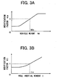
- the (final) target slip ratio Srfo is obtained by modifying the basic value Srfo' with respect to the vehicle weight and roll inertial moment as seen from the expression (1).
- Kw is determined as a function of vehicle weight W using a map in Fig. 3A , where the weight W is estimated based upon a sum of low-pass filtered data of vehicle height Hi obtained with the sensors 34i when the vehicle is stopped and running at a low speed.
- Wo is a weight of a vehicle under a standard condition.
- Ki is determined as a function of roll inertial moment I, using a map in Fig. 3B , where the roll inertial moment is estimated based upon a differential of a roll rate data Rr obtained with roll rate sensor 48.
- Io is roll inertial moment of a vehicle under a standard condition.
- the target slip ratio may be modified with the other parameters, such as yaw and/or pitch inertial moment, a vehicle speed, etc.
- braking force not only strong but also adapted to various characteristics of a vehicle, is generated for suppressing a behavioral deterioration of the vehicle.
- a conventional process may be executed for calculating target slip ratios on wheels.
- ⁇ is a slip angle of a vehicle
- dVy a side sliding acceleration of the vehicle
- d ⁇ a time differential of ⁇
- K1, K2 appropriate weight factors
- ⁇ t yaw rate estimated from the vehicle speed V and steering angle ⁇
- ⁇ an actual yaw rate
- H a wheel base.
- the parameters are defined as positive in the forward and leftward directions.
- dVy is given from the deviation between a lateral acceleration Gy and a product of yaw rate ⁇ and vehicle speed V: Gy - ⁇ V.
- Kh a stability factor
- T and s a time constant and frequency parameter in Laplace transformation.
- SS and DS each indicate degrees of spinning and drifting-out, respectively (The more deteriorated a behavior is, the larger either of the values is.).
- Fssfo is determined as a function of SS, using a map of Fig. 4A .
- Fsall is determined as a function of DS, using a map of Fig. 4B .
- Ksri is an appropriate distribution factor for rear wheels (a positive constant typically exceeding 0.5.). If a calculated value of Fsj is negative, it will be nullified.
- the above-defined force distribution generates anti-spin or anti-drift-out yaw moment as known in the art (The detailed effects of this force distribution are described elsewhere.).
- the resultant target force values are each converted into target values of slip ratios of the respective wheels in a way known in the art.
- the target slip ratios Srj may be increased as follows: Srj ⁇ Kg ⁇ Srj, where Kg is a positive constant between 1 and 1.5, for correcting the vehicle behavior, and thereby reducing a possibility of rolling-over if any, with anti-spin moment higher than normal anti-spin moment.
- the deviation of the actual value from the target value is fed back to the input of a braking force generating apparatus or a wheel cylinder (feedback control).
- duty ratios for pressure control valves for the wheel cylinders are calculated.
- the duty ratio for the turning outside front wheel is modulated for restricting the increasing and decreasing gradients of braking force when EASO is detected.
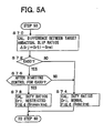
- Fig. 5A shows a control flow in an embodiment of the way of determination of duty ratios (in Step 50 in Fig. 2 ).
- Step 70 the difference between target and actual slip ratios on each wheel is determined.
- the current turning direction is judged as left or right with the sign of yaw rate or steering angle, etc., and then, target slip ratios calculated as the values for turning outside and inside, front and rear wheels in Step 30 or 40 are assigned to target slip ratios for left and right, front and rear wheels as follows:
- the actual slip ratio Srai on each wheel may be calculated from wheel speed Vwi from the sensors 32i and a vehicle speed V from the sensor 38.
- Step 40 duty ratio of either of the pair of pressure control valves for each wheel is determined as a function of the difference between the target and actual slip ratios (in Steps 72 and 74), using a map as indicated with the solid line in Fig. 6 .
- braking pressure will be increased ( ⁇ Sri>0: pressure increasing mode) or decreased ( ⁇ Sri ⁇ 0: pressure decreasing mode) by opening the corresponding pressure control valve at a duty ratio appropriately determined so as to cancel the deviation of the actual slip ratio from its target value as soon as possible, without control hunting, in a manner known in the art.
- the difference ⁇ Sri is very close to zero, none of the valves is opened as shown by the solid line around the 0 point (within ⁇ Sr0) in Fig. 6 (pressure holding mode).
- Step 72 the duty ratio for the turning outside front wheel is determined using a map as indicated with the broken line in Fig. 6 (Steps 72 and 78).
- the duty ratio is decreased so that the increasing or decreasing gradient of the slip ratio is restricted for avoiding rolling/pitching oscillation of the vehicle body due to transient braking force variation during the canceling of the difference between the actual and target slip ratios.
- EASO just after EASO, namely, before starting the control process of the slip ratio of the turning outside front wheel, it is anticipated that the actual value is far away from its target value (The difference between target and actual values is relatively large.).
- Step 76 whether or not the control using the target value calculated in Step 30 has been started is judged in Step 76, and, if it has not, the duty ratio is determined without the restriction in Step 74.
- the restriction of the increasing/decreasing gradient of the slip ratio is much effective for avoiding rolling/pitching oscillation under condition that a higher target slip ratio is set out.
- Fig. 5B the difference between the target and actual slip ratios on each wheel is determined as in Step 70 in Fig. 5A (Step 80), and duty ratio for each wheel is once determined using the map of the solid line in Fig. 6 (Step 82). Then, if EASO has not been detected (Step 84), no restriction of the duty ratio is executed.
- Step 84 whether or not either of rolling or pitching oscillation has been large is judged through Steps 86 and 88. In these judgments, for example, when a weighted sum of the magnitudes of a rolling (pitching) amount, calculated based upon the vehicle heights Hi monitored on each wheel, and a roll (pitch) rate, monitored with the sensor 48 (46), exceeds the corresponding reference value, the oscillation is judged as high. If the oscillations in both rolling and pitching directions are low, no restriction of duty ratio is executed.
- the duty ratio Drfl or Drfr of a front wheel is limited within the range between a lower limit A (negative) and an upper limit B (positive): if Drfl(fr) ⁇ A, then Drfl(fr) is set to A; if Drfl(fr)>B, Drfl(fr) is set to B (Step 90).
- the limits A and B may be determined fixedly or variably based upon roll inertial moment I and the other rolling and pitching parameters such as roll/pitching angles, rates. Preferably, the limits A and B are more away from zero as a roll inertial moment increases. Then, in step 92, the duty ratios of the rear wheels are set to zero.
- the duty ratios may be determined after a feedback amount is calculated as Kf ⁇ Sri, where Kf is a feedback gain. In such a case, Kf is reduced upon the restriction of the increasing/decreasing gradients of braking force.
- a possibility of rolling-over is determined in Step 20 in Fig. 2 by detecting EASO. It should be noted that the centrifugal force has not been increased yet and the vehicle behavior has not been highly deteriorated at the detection of EASO, i.e. just after the steered wheels are rotated. Thus, in the present embodiment, the control for reducing a possibility of rolling-over can be started in advance.
- EASO is not judged (a normal steering condition, NSO, is judged) when a vehicle speed V is low, i.e. V does not exceed a reference value Vo. This is because there is no risk of rolling-over during turning if the speed is low.
- Fig. 7A shows a flow of a process for detecting EASO.
- a reference value ⁇ 1 for a steering angle ⁇ is determined as a function of the vehicle speed V, using a map in Fig. 7B (Step 110) and a reference value d ⁇ 1 for a steering angular speed d ⁇ (the rotational speed of the steering angle) is determined as a function of the steering angle ⁇ , using a map as indicated with a solid line in Fig. 7C (Step 120).
- EASO is judged when the absolute value of the steering angle ⁇ : sign ⁇ , where sign ⁇ is the sign of ⁇ ( ⁇ 1), and the product of sign ⁇ and d ⁇ : sign ⁇ d ⁇ each exceed the respective reference values ⁇ 1 and d ⁇ 1 (S130, S135). If the steering wheel rotates in the direction opposite to the turning direction of the vehicle, sign ⁇ d ⁇ ⁇ 0 ⁇ d ⁇ 1. If either of the parameters ⁇ or d ⁇ does not exceed the corresponding reference value ⁇ 1 or d ⁇ 1, NSO is judged.
- the reference value ⁇ 1 decreases together with the increase of the vehicle speed V. This is because unallowable centrifugal force will be generated at a smaller angle as the vehicle speed increases.
- the angular speed reference value d ⁇ 1 decreases together with the increase of the steering angle, so that EASO can be detected in the region above the solid line in Fig 7C , wider than when d ⁇ 1 is determined irrespective of a steering angle ⁇ . In the latter case, EASO can be detected only in the region higher than the broken lines in Fig. 7C .
- the steering angle reference value ⁇ 1 may be determined as a function of yaw rate, lateral acceleration, etc. Further, it may be so designed that the angular speed reference value d ⁇ 1 is determined based upon the vehicle speed, yaw rate, lateral acceleration, etc. and the steering angle reference value ⁇ 1 is determined with the angular speed d ⁇ . In addition, judgment of a lateral acceleration Gy may be also done in the process, in which EASO is judged when Gy also exceeds a fixed positive reference value. Sensing Gy at this stage allows the monitoring of frictional condition on a road surface before the vehicle behavior is highly deteriorated. If Gy is low, the friction on the road surface can be considered as not too high.
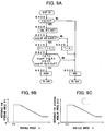
- Fig. 8A shows a flow of a process in the second example for detecting EASO.
- EASO is detected using a weighted sum of a steering angle and its angular speed, instead of the angular speed.
- Ka and Kb are set to decrease and to increase, respectively. This is because (1) when the steering angle is small, the contribution of the angular speed is to be small for avoiding a premature starting of the control process for reducing a possibility of rolling-over in Step 30; (2) when the steering angle is large, the control process should be started at a low angular speed.
- Step 220 when the following conditions are satisfied, EASO is judged: ⁇ w ⁇ ⁇ w ⁇ 2 ; sign ⁇ ⁇ ⁇ ⁇ ⁇ 2 ; V ⁇ V ⁇ 2 ; sign ⁇ ⁇ Gy ⁇ Gy ⁇ 2 , where V2 and Gy2 are reference values for the vehicle speed V and lateral acceleration Gy. If either of the conditions is not satisfied, NSO is judged.
- the reference values ⁇ w2, ⁇ 2 and the weights K1 and K2 may be determined as a function of yaw rate, lateral acceleration, etc. Further, these values may be modified based upon roll inertial moment (a liability to rolling) and/or a vehicle weight and/or height. Under certain running conditions, the condition (9c) or (9d) may be omitted.
- Fig. 9A shows a flow of a process in the third example for detecting EASO.
- EASO is judged when a steering angular speed is kept above a certain level.
- reference values ⁇ 3, d ⁇ 3 for a steering angle ⁇ and its speed d ⁇ are determined as functions of the vehicle speed V, using maps in Figs. 9B and 9C (step 305). Then, when the angular speed d ⁇ exceeds d ⁇ 3: sign ⁇ d ⁇ ⁇ d ⁇ 3, a time count T is started from 0 in Step 310. The time count T is incremented by ⁇ T in step 315 every cycle until T exceeds a reference period T3 or sign ⁇ d ⁇ falls below d ⁇ 3 (Step 320).
- Step 325) EASO is judged (S330). Otherwise, NSO is judged (Step 335). sign ⁇ ⁇ ⁇ ⁇ ⁇ ⁇ 3 V ⁇ V ⁇ 3 sign ⁇ ⁇ Gy ⁇ Gy ⁇ 3 where V3 and Gy3 are reference values for the vehicle speed V and lateral acceleration Gy.
- the reference values d ⁇ 3, ⁇ 3, T3 may be determined as a function of yaw rate, lateral acceleration, etc. Further, these values may be modified based upon roll inertial moment (a liability to rolling) and/or a vehicle weight and/or height. Under certain running conditions, the condition (10b) or (10c) may be omitted.
- Fig. 10A shows a flow of a process for detecting EASO in the fourth example of detection of EASO.
- a steering angular speed d ⁇ exceeds a reference value d ⁇ 4: d ⁇ d ⁇ 4. If it does, EASO will be judged when a steering angle ⁇ , an increment from the steering angle ⁇ in the turning direction, the vehicle speed V and a lateral acceleration Gy each exceed the respective reference values within a predetermined time period To from the time point of the satisfaction of d ⁇ d ⁇ 4.
- the reference values d ⁇ 4, ⁇ 4 and ⁇ for the angular speed d ⁇ , the steering angle ⁇ and the angular increment from the time of the satisfaction of d ⁇ d ⁇ 4 are determined as functions of the vehicle speed V, using maps in Figs. 10B, 10C and 10D , respectively (Step 410).
- Step 440 After the satisfaction of d ⁇ ⁇ d ⁇ 4 and before the lapse of the period To, it is judged in Step 440 if the following four conditions are satisfied: sign ⁇ ⁇ ⁇ ⁇ ⁇ ⁇ 4 ; V ⁇ V ⁇ 4 ; sign ⁇ ⁇ ⁇ ⁇ c + ⁇ sign ⁇ ⁇ Gy ⁇ Gy ⁇ 4 , where V4 and Gy4 are reference values for the vehicle speed V and lateral acceleration Gy. If these conditions are satisfied, EASO is judged.
- the condition (11c) allows the monitoring of the increase in the steering angle in the turning direction once after the steering angular speed exceeds the reference value d ⁇ 4 (it is possible that the angular speed temporally becomes directed opposite to the turning direction.).
- the variation or tendency of a driving operation changing future behavior of a vehicle can be monitored more precisely.
- the reference values d ⁇ 4, ⁇ 4, ⁇ may be determined as a function of yaw rate, lateral acceleration, etc. Further, under a certain condition, conditions (11b) and/or (11d) may be omitted.
Applications Claiming Priority (2)
| Application Number | Priority Date | Filing Date | Title |
|---|---|---|---|
| JP2003193744A JP4084248B2 (ja) | 2003-07-08 | 2003-07-08 | 車輌の挙動制御装置 |
| JP2003193744 | 2003-07-08 |
Publications (3)
| Publication Number | Publication Date |
|---|---|
| EP1495931A2 EP1495931A2 (en) | 2005-01-12 |
| EP1495931A3 EP1495931A3 (en) | 2006-02-08 |
| EP1495931B1 true EP1495931B1 (en) | 2013-09-04 |
Family
ID=33447989
Family Applications (1)
| Application Number | Title | Priority Date | Filing Date |
|---|---|---|---|
| EP04016129.1A Active EP1495931B1 (en) | 2003-07-08 | 2004-07-08 | Vehicle behavior control device |
Country Status (5)
| Country | Link |
|---|---|
| US (1) | US7337047B2 (ja) |
| EP (1) | EP1495931B1 (ja) |
| JP (1) | JP4084248B2 (ja) |
| KR (2) | KR100629121B1 (ja) |
| CN (1) | CN100540372C (ja) |
Families Citing this family (34)
| Publication number | Priority date | Publication date | Assignee | Title |
|---|---|---|---|---|
| US7640081B2 (en) * | 2004-10-01 | 2009-12-29 | Ford Global Technologies, Llc | Roll stability control using four-wheel drive |
| US20060267750A1 (en) * | 2005-05-26 | 2006-11-30 | Ford Global Technologies, Llc | Tire abnormal state monitoring system for an automotive vehicle |
| DE102005063343C5 (de) * | 2005-06-24 | 2019-07-11 | Knorr-Bremse Systeme für Nutzfahrzeuge GmbH | Verfahren zur Erhöhung der Fahrstabilität eines Fahrzeugs |
| KR101006917B1 (ko) * | 2005-11-23 | 2011-01-10 | 주식회사 만도 | 트레일러 진동 제어 방법 |
| KR100793869B1 (ko) * | 2005-12-17 | 2008-01-15 | 현대자동차주식회사 | 차량의 차간거리 제어 시스템 |
| JP4735415B2 (ja) * | 2005-12-21 | 2011-07-27 | トヨタ自動車株式会社 | 車両挙動制御装置 |
| JP4743024B2 (ja) * | 2006-07-03 | 2011-08-10 | トヨタ自動車株式会社 | 車両挙動制御装置 |
| JP2008143333A (ja) * | 2006-12-08 | 2008-06-26 | Toyota Motor Corp | 操作シミュレータ |
| FR2915161B1 (fr) * | 2007-04-17 | 2009-11-13 | Peugeot Citroen Automobiles Sa | Procede de controle de stabilite en boucle ouverte pour vehicule automobile. |
| JP4636062B2 (ja) * | 2007-08-27 | 2011-02-23 | トヨタ自動車株式会社 | 車両の挙動制御装置 |
| DE102007043911A1 (de) * | 2007-09-14 | 2009-03-19 | Robert Bosch Gmbh | Verfahren für die Steuerung eines Fahrerassistenzsystems |
| KR20090107334A (ko) * | 2008-04-08 | 2009-10-13 | 주식회사 만도 | 차량용 제동제어장치와 현가제어장치 간의 데이터통신을 통한 차고제어장치 및 그 제어방법 |
| US8019511B2 (en) * | 2008-05-22 | 2011-09-13 | Ford Global Technologies, Llc | Vehicle rollover detection |
| CN103144621B (zh) * | 2009-01-08 | 2015-05-27 | 株式会社小松制作所 | 牵引控制装置 |
| JP5113098B2 (ja) * | 2009-01-23 | 2013-01-09 | 日立オートモティブシステムズ株式会社 | 車両横転防止制御装置および車両横転防止制御方法 |
| US8352120B2 (en) * | 2009-02-17 | 2013-01-08 | Lockheed Martin Corporation | System and method for stability control using GPS data |
| JP5471078B2 (ja) | 2009-06-30 | 2014-04-16 | 株式会社アドヴィックス | 車両運動制御装置 |
| JP5418022B2 (ja) * | 2009-06-30 | 2014-02-19 | 株式会社アドヴィックス | 車両運動制御装置 |
| JP5375371B2 (ja) | 2009-06-30 | 2013-12-25 | 株式会社アドヴィックス | 車両運動制御装置 |
| JP5056954B2 (ja) * | 2009-07-17 | 2012-10-24 | トヨタ自動車株式会社 | 車両挙動制御装置 |
| DE102011080789B4 (de) | 2010-08-10 | 2022-11-10 | Continental Automotive Technologies GmbH | Verfahren und System zur Regelung der Fahrstabilität |
| JP5571519B2 (ja) * | 2010-09-27 | 2014-08-13 | 日立オートモティブシステムズ株式会社 | 車体姿勢制御装置 |
| JP5212663B2 (ja) * | 2010-10-21 | 2013-06-19 | トヨタ自動車株式会社 | 車両の制駆動力制御装置 |
| WO2012147165A1 (ja) * | 2011-04-26 | 2012-11-01 | トヨタ自動車株式会社 | 車両挙動制御システム |
| CN102259661A (zh) * | 2011-05-23 | 2011-11-30 | 奇瑞汽车股份有限公司 | 汽车侧滑方向校正控制系统及其控制方法 |
| US9376119B2 (en) * | 2013-02-08 | 2016-06-28 | Toyota Jidosha Kabushiki Kaisha | Vehicle-center-of-gravity condition determining apparatus and vehicle behavior control system |
| KR101619418B1 (ko) * | 2015-02-26 | 2016-05-18 | 현대자동차 주식회사 | 차량의 제동 장치 및 방법 |
| JP6984353B2 (ja) * | 2017-11-29 | 2021-12-17 | 株式会社アドヴィックス | 車両の制動制御装置 |
| CN108098770A (zh) * | 2017-12-14 | 2018-06-01 | 张辉 | 一种移动机器人的轨迹跟踪控制方法 |
| KR102005943B1 (ko) * | 2018-01-08 | 2019-08-01 | 주식회사 만도 | 차량 제어 장치 및 방법 |
| JP2019127095A (ja) * | 2018-01-23 | 2019-08-01 | マツダ株式会社 | 車両の制御装置 |
| JP6997061B2 (ja) * | 2018-10-09 | 2022-01-17 | トヨタ自動車株式会社 | 車両用制動制御装置 |
| JP2022147785A (ja) * | 2021-03-23 | 2022-10-06 | 本田技研工業株式会社 | 車両制御装置 |
| CN114643962B (zh) * | 2022-03-31 | 2023-03-14 | 上汽通用五菱汽车股份有限公司 | 一种车辆制动控制方法、装置和计算机设备 |
Family Cites Families (18)
| Publication number | Priority date | Publication date | Assignee | Title |
|---|---|---|---|---|
| JP3248414B2 (ja) * | 1995-10-18 | 2002-01-21 | トヨタ自動車株式会社 | 車輌の挙動制御装置 |
| DE19609717A1 (de) * | 1996-03-13 | 1997-09-18 | Bosch Gmbh Robert | Anordnung zum Erkennen von Überrollvorgängen bei Fahrzeugen |
| JP3570145B2 (ja) | 1997-02-25 | 2004-09-29 | トヨタ自動車株式会社 | 連結車のトレーラブレーキ制御装置 |
| JPH10329682A (ja) * | 1997-06-03 | 1998-12-15 | Mitsubishi Motors Corp | 車両の横転防止装置 |
| JP3982011B2 (ja) * | 1997-06-24 | 2007-09-26 | 三菱ふそうトラック・バス株式会社 | 車両の横転防止装置 |
| PT991543E (pt) | 1997-07-01 | 2004-10-29 | Dynamotive L L C | Sistema de travagem anti-capotagem |
| US6278930B1 (en) | 1999-06-01 | 2001-08-21 | Toyota Jidosha Kabushiki Kaisha | Device for controlling spin/driftout of vehicle compatibly with roll control |
| JP3705077B2 (ja) * | 1999-06-01 | 2005-10-12 | トヨタ自動車株式会社 | 車輌の運動制御装置 |
| US6139120A (en) | 1999-06-02 | 2000-10-31 | Toyota Jidosha Kabushiki Kaisha | Roll control device of vehicles with braking estimated and trimmed by separate parameters |
| US6304805B1 (en) * | 1999-07-21 | 2001-10-16 | Denso Corporation | Vehicle behavior estimating and controlling method and system as well as body slip angle estimating method and system |
| JP3463622B2 (ja) * | 1999-09-14 | 2003-11-05 | トヨタ自動車株式会社 | 車輌の挙動制御装置 |
| DE10049567B4 (de) * | 1999-10-08 | 2017-12-14 | Toyota Jidosha Kabushiki Kaisha | Fahrzeugsteuergerät zum Steuern eines allradgetriebenen Kraftfahrzeugs |
| DE10046036A1 (de) * | 2000-09-18 | 2002-03-28 | Knorr Bremse Systeme | Verfahren zum Abschätzen der Umkippgefahr eines Fahrzeugs |
| JP2002145035A (ja) * | 2000-11-10 | 2002-05-22 | Honda Motor Co Ltd | 車両の運動制御装置 |
| JP4547793B2 (ja) * | 2000-11-17 | 2010-09-22 | 株式会社アドヴィックス | 車両の運動制御装置 |
| DE10133409A1 (de) | 2001-07-13 | 2003-01-30 | Lucas Automotive Gmbh | Fahrzeugbremssystem |
| US7107136B2 (en) | 2001-08-29 | 2006-09-12 | Delphi Technologies, Inc. | Vehicle rollover detection and mitigation using rollover index |
| JP4090726B2 (ja) * | 2001-11-26 | 2008-05-28 | 横浜ゴム株式会社 | ブレーキ制御装置、ブレーキ制御方法および記録媒体 |
-
2003
- 2003-07-08 JP JP2003193744A patent/JP4084248B2/ja not_active Expired - Fee Related
-
2004
- 2004-06-15 KR KR1020040043939A patent/KR100629121B1/ko active IP Right Grant
- 2004-07-02 US US10/882,223 patent/US7337047B2/en active Active
- 2004-07-08 CN CNB2004100633725A patent/CN100540372C/zh active Active
- 2004-07-08 EP EP04016129.1A patent/EP1495931B1/en active Active
-
2006
- 2006-05-29 KR KR1020060048142A patent/KR100791826B1/ko active IP Right Grant
Also Published As
| Publication number | Publication date |
|---|---|
| KR20050006035A (ko) | 2005-01-15 |
| EP1495931A3 (en) | 2006-02-08 |
| KR100629121B1 (ko) | 2006-09-27 |
| CN1576124A (zh) | 2005-02-09 |
| KR20060083927A (ko) | 2006-07-21 |
| US7337047B2 (en) | 2008-02-26 |
| KR100791826B1 (ko) | 2008-01-04 |
| JP4084248B2 (ja) | 2008-04-30 |
| JP2005028919A (ja) | 2005-02-03 |
| EP1495931A2 (en) | 2005-01-12 |
| CN100540372C (zh) | 2009-09-16 |
| US20050029754A1 (en) | 2005-02-10 |
Similar Documents
| Publication | Publication Date | Title |
|---|---|---|
| EP1495931B1 (en) | Vehicle behavior control device | |
| EP1640231A1 (en) | Motor vehicle control using a dynamic feedforward approach | |
| KR100642023B1 (ko) | 차량의 거동 제어장치 | |
| EP0893320B1 (en) | Behavior control device of vehicle having means for avoiding miscontrol due to neutral shift of yaw rate sensor | |
| JP3546830B2 (ja) | 車輌のロール挙動制御装置 | |
| EP1595768B1 (en) | Vehicle running control device | |
| EP1510438B1 (en) | Control device for vehicle power steering | |
| EP3659878B1 (en) | Vehicle disturbance detection apparatus | |
| JP3695164B2 (ja) | 車輌の挙動制御方法 | |
| US7792620B2 (en) | Driving dynamics control adapted to driving conditions and based on steering interventions | |
| US20060158031A1 (en) | Method and system for controlling the driving stability of a vehicle and use of said system | |
| EP1386807B1 (en) | System and method for determining a wheel departure angle for a rollover control system | |
| US20100023235A1 (en) | Method and Device For Stabilizing A Single-Track Motor Vehicle | |
| US7775608B2 (en) | Method for controlling a brake pressure | |
| US7668637B2 (en) | Technique for determining motor vehicle slip angle while accounting for road banks | |
| EP1370456B1 (en) | A vehicle steering system having oversteer assistance | |
| JP3705077B2 (ja) | 車輌の運動制御装置 | |
| US7493201B2 (en) | Method and apparatus for controlling active front steering | |
| JP2005271821A (ja) | 車両の挙動制御装置 | |
| EP1837262A1 (en) | Motor vehicle control using a dynamic feedforward approach | |
| US20050143885A1 (en) | Rollover stability system including allowance for the steering angle | |
| JP2005350054A (ja) | 車輌の走行制御装置 | |
| JP2001163205A (ja) | 車両の運動制御装置 | |
| JP2002154417A (ja) | 車輌の挙動制御装置 | |
| KR20070060507A (ko) | 차량 자세 제어장치 및 그 제어방법 |
Legal Events
| Date | Code | Title | Description |
|---|---|---|---|
| PUAI | Public reference made under article 153(3) epc to a published international application that has entered the european phase |
Free format text: ORIGINAL CODE: 0009012 |
|
| AK | Designated contracting states |
Kind code of ref document: A2 Designated state(s): AT BE BG CH CY CZ DE DK EE ES FI FR GB GR HU IE IT LI LU MC NL PL PT RO SE SI SK TR |
|
| AX | Request for extension of the european patent |
Extension state: AL HR LT LV MK |
|
| PUAL | Search report despatched |
Free format text: ORIGINAL CODE: 0009013 |
|
| AK | Designated contracting states |
Kind code of ref document: A3 Designated state(s): AT BE BG CH CY CZ DE DK EE ES FI FR GB GR HU IE IT LI LU MC NL PL PT RO SE SI SK TR |
|
| AX | Request for extension of the european patent |
Extension state: AL HR LT LV MK |
|
| 17P | Request for examination filed |
Effective date: 20060512 |
|
| 17Q | First examination report despatched |
Effective date: 20060726 |
|
| AKX | Designation fees paid |
Designated state(s): DE FR GB SE |
|
| RAP1 | Party data changed (applicant data changed or rights of an application transferred) |
Owner name: TOYOTA JIDOSHA KABUSHIKI KAISHA |
|
| GRAP | Despatch of communication of intention to grant a patent |
Free format text: ORIGINAL CODE: EPIDOSNIGR1 |
|
| GRAS | Grant fee paid |
Free format text: ORIGINAL CODE: EPIDOSNIGR3 |
|
| GRAA | (expected) grant |
Free format text: ORIGINAL CODE: 0009210 |
|
| AK | Designated contracting states |
Kind code of ref document: B1 Designated state(s): DE FR GB SE |
|
| REG | Reference to a national code |
Ref country code: GB Ref legal event code: FG4D |
|
| RIN1 | Information on inventor provided before grant (corrected) |
Inventor name: YAMADA, NORITAKA Inventor name: KOBAYASHI, YASUSHI Inventor name: UENO, HIROSHI Inventor name: MIWA, YUKIHISA |
|
| REG | Reference to a national code |
Ref country code: DE Ref legal event code: R096 Ref document number: 602004043220 Country of ref document: DE Effective date: 20131031 |
|
| REG | Reference to a national code |
Ref country code: SE Ref legal event code: TRGR |
|
| REG | Reference to a national code |
Ref country code: GB Ref legal event code: 746 Effective date: 20140304 |
|
| REG | Reference to a national code |
Ref country code: DE Ref legal event code: R084 Ref document number: 602004043220 Country of ref document: DE Effective date: 20140304 |
|
| REG | Reference to a national code |
Ref country code: DE Ref legal event code: R097 Ref document number: 602004043220 Country of ref document: DE |
|
| PLBE | No opposition filed within time limit |
Free format text: ORIGINAL CODE: 0009261 |
|
| STAA | Information on the status of an ep patent application or granted ep patent |
Free format text: STATUS: NO OPPOSITION FILED WITHIN TIME LIMIT |
|
| 26N | No opposition filed |
Effective date: 20140605 |
|
| REG | Reference to a national code |
Ref country code: DE Ref legal event code: R097 Ref document number: 602004043220 Country of ref document: DE Effective date: 20140605 |
|
| REG | Reference to a national code |
Ref country code: FR Ref legal event code: PLFP Year of fee payment: 12 |
|
| PGFP | Annual fee paid to national office [announced via postgrant information from national office to epo] |
Ref country code: DE Payment date: 20150630 Year of fee payment: 12 |
|
| PGFP | Annual fee paid to national office [announced via postgrant information from national office to epo] |
Ref country code: SE Payment date: 20150713 Year of fee payment: 12 Ref country code: FR Payment date: 20150629 Year of fee payment: 12 |
|
| REG | Reference to a national code |
Ref country code: DE Ref legal event code: R119 Ref document number: 602004043220 Country of ref document: DE |
|
| REG | Reference to a national code |
Ref country code: SE Ref legal event code: EUG |
|
| PG25 | Lapsed in a contracting state [announced via postgrant information from national office to epo] |
Ref country code: FR Free format text: LAPSE BECAUSE OF NON-PAYMENT OF DUE FEES Effective date: 20160801 Ref country code: DE Free format text: LAPSE BECAUSE OF NON-PAYMENT OF DUE FEES Effective date: 20170201 Ref country code: SE Free format text: LAPSE BECAUSE OF NON-PAYMENT OF DUE FEES Effective date: 20160709 |
|
| REG | Reference to a national code |
Ref country code: FR Ref legal event code: ST Effective date: 20170331 |
|
| PGFP | Annual fee paid to national office [announced via postgrant information from national office to epo] |
Ref country code: GB Payment date: 20230601 Year of fee payment: 20 |
|
| P01 | Opt-out of the competence of the unified patent court (upc) registered |
Effective date: 20231024 |