EP1837262A1 - Motor vehicle control using a dynamic feedforward approach - Google Patents
Motor vehicle control using a dynamic feedforward approach Download PDFInfo
- Publication number
- EP1837262A1 EP1837262A1 EP07075420A EP07075420A EP1837262A1 EP 1837262 A1 EP1837262 A1 EP 1837262A1 EP 07075420 A EP07075420 A EP 07075420A EP 07075420 A EP07075420 A EP 07075420A EP 1837262 A1 EP1837262 A1 EP 1837262A1
- Authority
- EP
- European Patent Office
- Prior art keywords
- motor vehicle
- control
- esc
- vehicle
- yaw rate
- Prior art date
- Legal status (The legal status is an assumption and is not a legal conclusion. Google has not performed a legal analysis and makes no representation as to the accuracy of the status listed.)
- Withdrawn
Links
Images


Classifications
-
- B—PERFORMING OPERATIONS; TRANSPORTING
- B60—VEHICLES IN GENERAL
- B60T—VEHICLE BRAKE CONTROL SYSTEMS OR PARTS THEREOF; BRAKE CONTROL SYSTEMS OR PARTS THEREOF, IN GENERAL; ARRANGEMENT OF BRAKING ELEMENTS ON VEHICLES IN GENERAL; PORTABLE DEVICES FOR PREVENTING UNWANTED MOVEMENT OF VEHICLES; VEHICLE MODIFICATIONS TO FACILITATE COOLING OF BRAKES
- B60T8/00—Arrangements for adjusting wheel-braking force to meet varying vehicular or ground-surface conditions, e.g. limiting or varying distribution of braking force
- B60T8/17—Using electrical or electronic regulation means to control braking
- B60T8/1755—Brake regulation specially adapted to control the stability of the vehicle, e.g. taking into account yaw rate or transverse acceleration in a curve
- B60T8/17554—Brake regulation specially adapted to control the stability of the vehicle, e.g. taking into account yaw rate or transverse acceleration in a curve specially adapted for enhancing stability around the vehicles longitudinal axle, i.e. roll-over prevention
-
- B—PERFORMING OPERATIONS; TRANSPORTING
- B60—VEHICLES IN GENERAL
- B60T—VEHICLE BRAKE CONTROL SYSTEMS OR PARTS THEREOF; BRAKE CONTROL SYSTEMS OR PARTS THEREOF, IN GENERAL; ARRANGEMENT OF BRAKING ELEMENTS ON VEHICLES IN GENERAL; PORTABLE DEVICES FOR PREVENTING UNWANTED MOVEMENT OF VEHICLES; VEHICLE MODIFICATIONS TO FACILITATE COOLING OF BRAKES
- B60T2230/00—Monitoring, detecting special vehicle behaviour; Counteracting thereof
- B60T2230/03—Overturn, rollover
Landscapes
- Engineering & Computer Science (AREA)
- Transportation (AREA)
- Mechanical Engineering (AREA)
- Regulating Braking Force (AREA)
- Steering Control In Accordance With Driving Conditions (AREA)
Abstract
Description
- The present invention is generally directed to motor vehicle control and, more specifically, to motor vehicle control using a dynamic feedforward approach.
- Various active control systems have been proposed and/or implemented that have controlled the brakes, steering and/or suspension of a motor vehicle to better allow a driver of the motor vehicle to maintain control of the vehicle under varying circumstances and conditions. In general, these control systems have attempted to improve motor vehicle performance in various driving conditions by coordinating control of multiple vehicle subsystems. Typically, such control systems have utilized a reference model, a state estimator and a vehicle control unit, which has incorporated feedback control in conjunction with feedforward control.
- Similarly, a number of active control systems have been proposed to reduce the likelihood of motor vehicle rollover. In general, the design of these systems has been based on roll state dynamics. Typically, yaw rate stability control systems have been designed with consideration for yaw-plane motion and have ignored roll motion. Additionally, rollover stability control systems have been designed for roll motion and have ignored yaw-plane motion. In general, brake-based control designers have experienced difficulty in developing a strategy that coordinates rollover and yaw stability.
- A number of motor vehicles have included electronic stability control (ESC), which is a closed-loop stability control system that relies on antilock brake system (ABS) and traction control system (TCS) components. A typical ESC system incorporates sensors for determining vehicle states, as well as an electronic control unit (ECU) to modulate braking and traction forces responsive to signals provided by the sensors. Various ESC systems have included wheel speed sensors, a steering wheel angle sensor, yaw rate and lateral acceleration sensors and master cylinder pressure sensors.
- In general, the steering wheel angle sensor has provided a steering wheel angle and a steering input rate. The wheel speed sensors have provided signals that the ECU uses to compute the speed of the wheels. Typically, the vehicle speed is derived from the rotational speeds of all wheels using a computational algorithm. The yaw rate sensor has usually been implemented as a gyroscopic sensor that monitors a rotation about a vertical axis of the motor vehicle. The lateral acceleration sensor has been positioned to measure the acceleration of the vehicle in the direction of the lateral axis of the vehicle, i.e., the side-to-side motion of the vehicle. In a typical ESC system, the ECU includes a microprocessor that processes and interprets the information from each of the sensors and then generates necessary activation commands to control brake pressure and engine torque.
- The concept behind an ESC system is to provide an active safety system that helps a motor vehicle operator prevent skidding that can occur in various kinds of weather, on different types of roads and in situations where even expert drivers may struggle to maintain their vehicles on the roadway. The stabilizing effect provided by an ESC system is based on calculations performed by the microprocessor of the ECU, which evaluates signals provided from the various sensors. The microprocessor utilizes the information provided by the sensors to continuously compare the actual and desired movement of the vehicle and intervene if the vehicle shows a tendency to leave an intended travel path. The ESC stabilizing effect is achieved by automatically applying a differential brake force (i.e. a difference between the left side and right side longitudinal braking forces), which affects the turning motion of the vehicle and helps to keep it on the intended path.
- Typically, a control algorithm implemented by the microprocessor utilizes program setpoints, which are tailored to a particular vehicle and specific operations of the vehicle. The microprocessor of the ESC system then transmits appropriate commands to the braking system, to cause the braking system to provide a defined brake pressure at an appropriate wheel, depending upon the deviation of the motor vehicle from a desired path. The microprocessor may also command the vehicle to reduce engine torque during understeering or when wheel spin is detected during acceleration.
- What is needed is an active control system that manages yaw-plane motion, while also comprehending and managing roll motion. It would also be desirable if the control system was capable of providing handling enhancements for an electronic stability control system implementing brake-based control.
- According to one embodiment of the present invention, a dynamic feedforward (DFF) electronic stability control (ESC) system for a motor vehicle includes at least one sensor, a control unit and an ESC actuator. The at least one sensor provides a driver input. The control unit implements a dynamic reference model algorithm that receives the driver input and provides a desired behavior. The control unit also implements a feedforward control algorithm that receives the desired behavior as an input and determines an ESC differential force target in response thereto. The control unit converts the ESC differential force target into longitudinal wheel slip targets or equivalently a "delta velocity (DVLR) command," which is provided to the ESC actuator. The ESC actuator controls a vehicle subsystem responsive to the DVLR command to provide a desired motion correction to the motor vehicle.
- According to another aspect of the present invention, the driver input includes a steering angle and a vehicle speed. According to a different aspect of the present invention, the reference model algorithm models one of a motor vehicle yaw rate and a motor vehicle roll angle.
- According to another embodiment of the present invention, a control system for a motor vehicle that coordinates yaw-plane motion and roll motion of the motor vehicle includes at least one sensor, a control unit and an electronic stability control (ESC) actuator. The at least one sensor provides a plurality of driver inputs that include a steering angle and a motor vehicle speed. The control unit implements a reference model algorithm that receives the plurality of driver inputs and provides a desired yaw rate. The control unit also implements a roll motion prediction model algorithm that predicts when roll motion of the vehicle may be severely excited by yaw-plane motion. The control unit modifies the desired yaw rate when roll motion excitation exceeds a desired level. The control unit implements a plant model algorithm that provides a predicted yaw rate based upon the steering angle and rate. The control unit determines an error term, based upon the desired yaw rate and the predicted yaw rate, and provides a delta velocity (DVLR) command to the ESC actuator to manage roll motion excitation by providing a desired correction to the motor vehicle.
- According to yet another embodiment of the present invention, a control system for a motor vehicle that coordinates yaw-plane motion and roll motion of the motor vehicle includes at least one sensor, a control unit and an electronic stability control (ESC) actuator. The at least one sensor provides a plurality of driver inputs that include a steering angle, a motor vehicle speed and an actual yaw rate. The control unit implements a reference model algorithm that receives the plurality of driver inputs and provides a desired yaw rate. The control unit also implements a roll motion prediction model algorithm that predicts when roll motion of the vehicle may be severely excited by yaw-plane motion. The control unit determines an error term, based upon the desired yaw rate and the actual yaw rate, and provides a delta velocity (DVLR) command to the ESC actuator to manage roll motion excitation by providing a desired correction to an associated motor vehicle.
- These and other features, advantages and objects of the present invention will be further understood and appreciated by those skilled in the art by reference to the following specification, claims and appended drawings.
- The present invention will now be described, by way of example, with reference to the accompanying drawings, in which:
- Fig. 1 depicts a block diagram representing the physical relationship of a steering input, a brake control system and their influence on a motor vehicle's motion;
- Fig. 2 depicts further details of the structure of Fig. 1;
- Fig. 3 depicts an exemplary dynamic feedforward (DFF) control routine for a full order ESC system that operates on a desired roll angle;
- Fig. 4A depicts a DFF control routine for a full order ESC system that operates on a desired yaw rate;
- Fig. 4B depicts a DFF control routine for a reduced order ESC system that operates on a desired yaw rate;
- Fig. 5A is a graph that includes curves that illustrate a brake pressure over time for an ESC system with DFF control, according to Fig. 3, and a base ESC system;
- Fig. 5B is a graph that includes curves that depict a roll angle as a function of time for an ESC system with DFF control, according to Fig. 3, and a base ESC system;
- Fig. 5C is a graph that includes curves that depict a yaw rate as a function of time for an ESC system with DFF control, according to Fig. 3, and a base ESC system;
- Fig. 5D is a graph showing curves that show a tire sideslip angle as a function of time for an ESC system with DFF control, according to Fig. 3, and a base ESC system;
- Fig. 6A is a graph that includes curves that plot a brake pressure over time for an ESC system with DFF control, according to Fig. 3, and a base ESC system;
- Fig. 6B is a graph that includes curves that plot a rollover angle as a function of time for an ESC system with DFF control, according to Figs. 4A-4B, and a base ESC system;
- Fig. 6C is a graph that includes curves that plot yaw rate as a function of time for an ESC system with DFF control, according to Figs. 4A-4B, and a base ESC system;
- Fig. 6D is a graph that includes curves that plot a tire sideslip angle as a function of time for an ESC system with DFF control, according to Figs. 4A-4B, and a base ESC system;
- Figs. 7A-7B are schematics of a yaw-plane and roll motion, respectively, for a motor vehicle;
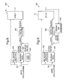
- Fig. 8 is a block diagram of a control structure implementing feedforward control, according to one embodiment of the present invention;
- Fig. 9 is a block diagram of a control structure implementing feedforward control of roll mode, according to another embodiment of the present invention;
- Fig. 10A is a performance graph for a motor vehicle in a fishhook maneuver that includes response curves with different desired yaw rates;
- Fig. 10B is a performance graph for a motor vehicle in another fishhook maneuver that includes response curves with different desired yaw rates;
- Figs. 11A-11D are performance graphs for a motor vehicle in a fishhook maneuver without feedforward control;
- Figs. 12A-12D are performance graphs for a motor vehicle in a fishhook maneuver with feedforward control, according to the control structure of Fig. 8; and
- Figs. 13A-13D are performance graphs for a motor vehicle in a fishhook maneuver with feedforward control of roll mode, according to the control structure of Fig. 9.
- According to one aspect of the present invention, a motor vehicle control algorithm is employed that uses a single-point tuning approach by computing a feedforward control term as a function of desired reference model behavior. The desired reference model utilizes steering angle, vehicle speed and roll motion dynamics and may model a motor vehicle yaw rate or a motor vehicle roll angle.
- With reference to Fig. 1, a
system 100, which implements feedforward control ofmotor vehicle 10 handling dynamics, is depicted. As is shown, the vehicle outputs are vehicle handling motion variables, such as yaw rate or roll angle. Thevehicle 10 responds to two inputs, i.e., a steering input and a differential brake force input. The differential brake force is automatically generated by abrake control system 12 that includes a feedforward control. The differential brake force is specifically a difference in brake force on the left side and right side of thevehicle 10, intended to affect the rotation of the vehicle. - With reference to Fig. 2, further details of the
system 100 are shown. Gref is a reference model transfer function that relates a steering angle δF to a desired vehicle motion signal Φdesired. Gref represents the desired vehicle motion, which is different in some aspects than the natural motion. For example Gref may have higher damping and/or lower static gain of the yaw or roll modes, and it may be dependent on vehicle speed. Gff is a feedforward control transfer function that relates the desired motion signal to a differential brake force command. P1 is a transfer function that relates steering input to a vehicle motion output Φ (yaw rate or roll angle). P1 represents the natural response of vehicle to driver (steering) input, without any control intervention. P2 is the transfer function that relates differential brake force input to a vehicle motion output Φ (yaw rate or roll angle). Both P1 and P2 are known to be dependent on vehicle speed. - Transfer functions Gref and Gff are intended to be implemented as discrete-time equations that are calculated by a microprocessor within an electronic control unit (ECU) of the brake system. The transfer functions P1 and P2 mathematically represent the physic principles that govern the vehicle motion with respect to steering and braking force inputs.
- Using the
system 100 structure as shown in Fig. 2, the transfer functions Gref and Gff are determined in the following way. First, the desired vehicle motion response is chosen, based on performance criteria, and this is then used to establish the desired parameters for the Gref reference model transfer function, such as desired gain, desired damping, desired natural frequency, and others. This relationship can be described as:
- The feedforward control transfer function Gff can then be determined as shown by the following derivation, starting with the equation that represents the system of Fig. 2:

As the actual motion response should be equal to the desired motion response, the two equations are set equal, as is set forth below:
Substitutingequations equation 3 yields:
which can then be solved for the feedforward control transfer function, giving:
- It is known that several transfer function parameters in P1 and P2 are dependent on vehicle speed. It is also expected that the desired transfer function Gref will intentionally change with vehicle speed based on performance requirements. Thus, it is expected that the feedforward control Gff will also change with vehicle speed.
- For practical implementation of the control described above, there are two items that may be considered. First, due to the intrusive nature of a brake-based control, it is frequently desirable to implement a deadband to prevent unwanted activations of the vehicle brake subsystem. A deadband can be implemented on the output of the feedforward control calculation so as to prevent brake activations when the control output magnitude is below a specified threshold. Secondly, it is recognized that the inverse of some transfer functions may not be directly implementable. This problem is avoided by the fact that each individual transfer function inversion does not need to be implemented alone, but instead only the overall control transfer function, i.e., Gff * Gref, needs to be implemented. Based on the above description, it should be appreciated that the system of Fig. 2 will provide a desirable response. The brake system controller output (i.e., the differential brake force command) is calculated during each execution of the control algorithm by passing the measured steering angle signal through a set of equations that represent the speed-dependent transfer functions for Gref and Gff. The differential brake force, derived from the feedforward controller, will then shape the dynamic vehicle motion to achieve the desired response.
- Fig. 3 sets forth an exemplary
DFF control routine 300 for a full order ESC system that operates on a desired roll angle reference model. In step 302, the routine 300 is initiated, at which point control transfers to step 304, where the microprocessor obtains three degree-of-freedom (DOF) vehicle model parameters, such as mass/inertia, tire corner stiffness on a high coefficient of friction surface (high-co), roll stiffness, roll damping, vehicle center of gravity height and roll center height (RCH). Next, instep 306, a filtered steering wheel position and vehicle speed are determined. Then, instep 308, a nonlinear vehicle/tire parameter adaptation is performed (e.g., tire cornering stiffness may change as a function of a static desired lateral acceleration Ay), based on the lateral acceleration Ay, e.g., calculated from steering angle and speed. Next, instep 310, a desired frequency and damping for a reference model that includes a transfer function having two zeroes and four poles is determined. Then, instep 312, a desired differential brake force is calculated for a transfer function that includes six zeroes and six poles. Next, instep 314, the desired differential brake force is converted to a DVLR command signal, at which point control transfers to step 316, where the routine 300 returns to a calling routine. The calling routine then passes the DVLR command signal to an actuator control algorithm which generates brake force commands based on the DVLR command signal. - With reference to Fig. 4A, a
DFF control routine 400 for a full order ESC system utilizing a desired yaw rate reference model is depicted. In step 402, the routine 400 is initiated, at which point control transfers to step 404, where three DOF vehicle model parameters are obtained. Next, instep 406, a filtered steering wheel position and vehicle speed are obtained. Then, instep 408, nonlinear vehicle/tire parameter adaptations, based on a static desired lateral acceleration Ay, are initiated. Next, instep 410, a desired frequency and damping for a reference model having a transfer function with three zeroes and four poles are determined. Then, instep 412, a differential brake force is calculated for a transfer function having seven zeroes and seven poles. Next, instep 414, an appropriate DVLR command signal is determined for the differential brake force, at which point control transfers to step 416, where the routine returns to a calling routine. - With reference to Fig. 4B, a
DFF control routine 420 for a reduced order ESC system utilizing a desired yaw rate reference model is depicted. In step 422, the routine 420 is initiated, at which point control transfers to step 424, where two DOF vehicle model parameters are obtained. Next, instep 426, a filtered steering wheel position and a vehicle speed are obtained. Then, instep 428, nonlinear vehicle/tire parameter adaptations, based on a static desired lateral acceleration Ay, are performed. Next, instep 430, a desired frequency and damping for a reference model that includes a transfer function having one zero and two poles is determined. Then, instep 432, the differential brake force for a transfer function having three zeroes and three poles is calculated. Next, instep 434, an appropriate DVLR command signal is determined from the differential brake force, at which point control transfers to step 436, where the routine 420 returns to a calling routine. - Figs. 5A-5D depict graphs of simulation results for a motor vehicle, during a National Highway Traffic Safety Administration (NHTSA) fish-hook maneuver on a dry surface, that illustrate motor vehicle control implemented in an ESC system with DFF control (according to Figs. 4A-4B) and for a base ESC system, for a desired yaw rate reference model. According to one embodiment, ESC based motor vehicle control is activated if the absolute value of the DVLR signal exceeds a preset threshold. The threshold may be a function of speed, e.g., greater than 20 KPH, and brake actuation is in the same direction as the DVLR signal. That is, a positive DVLR signal indicates a need to generate a clockwise yaw moment, which is achieved by applying one or two brakes on the right side of the vehicle. Conversely, a negative DVLR signal indicates a need to generate a counterclockwise yaw moment, which is achieved by applying one or two brakes on the left side of the vehicle.
- The
graph 500 of Fig. 5A depictscurves graph 510 includescurves graph 520 havingcurves graph 530 includingcurves - Figs. 6A-6D correspond to simulation curves for the vehicle utilized to provide the results of Figs. 5A-5D, with the addition of a 200 kilogram payload applied on a top roof of the vehicle. With reference to Fig. 6A, a
graph 600 includescurves graph 610 includescurves graph 620 that includescurves graph 630 that plots a tire sideslip angle as a function of time and includescurves - According to another embodiment of the present invention, a control system is designed to manage yaw-plane motion, while also comprehending and managing roll motion. The control system advantageously accounts for both yaw-plane and roll motion and, thus, avoids coordination problems. As maneuver-induced roll motion is a function of yaw-plane motion, it is possible to reduce maneuver-induced roll motion by properly shaping the yaw-plane motion. Proper shaping of the yaw-plane motion may include increasing yaw damping and/or decreasing a yaw gain, or simply reducing the magnitude of desired yaw rate under various conditions, to avoid excitation of roll dynamics. According to one embodiment of the present invention, the roll motion is predicted, based upon the severity of steering inputs, and not based upon measured vehicle response provided by a roll rate sensor or lateral acceleration sensor.
- According to the present invention, braking is controlled to generate a required yaw moment, via differential braking, to properly shape yaw-plane motion of the vehicle and to limit the roll motion of the vehicle. In general, a control system, constructed according to this embodiment of the present invention, is based upon a reference model control approach that provides a reference model control structure that may be utilized for both a feedforward configuration and a feedback configuration. In this embodiment, the reference model generates a desired yaw rate (using steering angle and speed) and may utilize the yaw rate in a feedback loop. As implemented, roll motion prediction logic decides when to dynamically adjust the reference model, to shape the reference model output, i.e., the desired yaw response, to prevent excessive roll motion excitation. It should be appreciated that excessive roll motion may be indicated when a combination of steering angle and steering rate is large for a given speed. It should also be appreciated that other motor vehicle conditions may also be utilized to predict excessive roll motion. In any case, when excessive roll motion is indicated, the desired yaw response is adjusted. The adjustment is made to limit or slow down, e.g., damp, the yaw motion of the vehicle, so as to reduce the roll motion.
- It should be appreciated that a number of techniques may be implemented to provide the desired adjustment. One possibility is to generate two values of desired yaw rate, e.g., the value normally used, YRdesnorm, and the value that changes more slowly in response to the steering input, YRdesslow, and then calculate the final, actually used, value as a weighted sum of the two above values. That is:

where w is a weighting constant, which varies from 0 to 1. The weight is selected in such a way that during normal operation w=0 and the desired yaw rate is equal to the normally used value, i.e., YRdes=yRdesnorm. The weight increases when the large roll motion is predicted. The normal value of the desired yaw rate can be determined primarily from steering angle and vehicle speed, as has been done in ESC systems and is known to those skilled in the art. When w=1, the desired value of yaw rate is equal to the slow value, YRdes= YRdesslow, and the desired value is between normal and slow when 0<w<1. The slow value of desired yaw rate, YRdesslow, can be obtained for example by passing the desired normal value, YRdesnorm, through a low pass filter with a static gain of 1, or less than 1 if reduction in magnitude of desired yaw rate is required. The low pass filter may have a form a0/(s+a1) where s is the Laplace operand, a0 and a1 are constants. If a0=a1, the static gain of the filter may be set equal to 1. If a0<a1, the gain may be set less than 1. - As explained above, the value of weight w is equal to zero during normal driving, and it increases continuously to 1 when large roll angle is predicted. In general, large roll angle is predicted when the steering angle and steering rate are large for given speed. An example calculation of the weigh w is illustrated below. First, in the process of calculating the normal desired yaw rate, YRdesnorm, a steady-state value of desired yaw rate, YRdss, is calculated as a function of front steering angle δF and vehicle speed Vx. If it is not available, the steady-state value can be computed as:

where L is vehicle wheelbase and Ku understeer gradient. The product of steady-state desired yaw rate and speed represents the steady-state desired lateral acceleration, which may be considered a predicted value of actual lateral acceleration. Next, a proportional and derivative (PD) term of the product of YRdss and vehicle speed is calculated as follows:
where ε is a positive constant, for example 0.4. Subsequently, the weight, w, may be determined as a function of magnitude of AydPD as follows:
where sat0,1 is a saturation function, which limits the value of operand from 0 to 1 and C1 and C2 are constant values, for example, C1=12 m/s2 and C2=10 m/s2. It is seen that during normal driving, when AydPD<C1, w=0, and in extremely severe maneuvers, when AydPD>C1+C2, then w=1. The rate of change of the weight w is then limited when w is decreasing to a specific value, for example 0.5 at 1 second. - Other ways of adjusting (generally by limiting the rate of change and magnitude of the desired yaw rate) may be used, as can be readily contemplated by those skilled in art. After the desired yaw rate is determined, the control of vehicle yaw motion can be accomplished in the same manner as in ESC systems. This aspect is well known to those skilled in art.
- With reference to Fig. 7A, it should be appreciated that by controlling vehicle yaw-plane motion, excessive maneuver-induced roll motion can be avoided. As is shown, turning the front wheels of a motor vehicle to the right causes lateral forces FyLF, FyRF, FyLR and FyRR to act on the front and rear tires, produces a yaw rate YR and induces a lateral acceleration Ay on the vehicle. With reference to Fig. 7B, it should be appreciated that roll motion may be induced by rapidly changing lateral forces Fy, which excite the roll mode. According to the present invention, yaw-plane motion is controlled such that excessive maneuver-induced roll motion is avoided.
- Fig. 8 depicts an exemplary
feedforward control structure 800 that receives speed andsteering inputs 801. Theinputs 801 are applied to an excessive rollmotion prediction model 802, areference model 804 and aplant model 806. Thereference model 804 calculates a desired yaw rate and, when excessive roll motion is possible, the desired yaw rate is adjusted to limit and/or slow down, i.e., damp, the vehicle's yaw-plane motion. The desired yaw rate is then compared to a predicted yaw rate, provided by theplant model 806, to form an error term, which is provided to an input of acontrol algorithm 808 that, in response thereto, generates a differential brake force command (Delta Fx), which is provided to a brake subsystem of the vehicle. - With reference to Fig. 9, another exemplary
feedback control structure 900 is depicted that is similar to thestructure 800, with the exception that theplant model 806 has been replaced withsensors 910 that provide a measurement or an estimation of an actual yaw rate. Thus, in thesystem 900, the actual yaw rate is provided from a sensor instead of being predicted. This modification tends to improve robustness to variations. Thus, by using steering angle and speed, lateral acceleration and its rate of change may be predicted. According to this embodiment, a linear combination of lateral acceleration and its rate of change is used to predict excessive roll motion. When the linear combination is above a threshold, the reference model is gradually modified. - According to the present invention, the rate of change may also be reduced when the linear combination is decreasing in order to prevent jerky control and early exit from the control routine. In general, during excessive roll motion, the reference model, which is generating the desired yaw rate, is modified by increasing a damping ratio in a dynamic second order filter of the reference model, or reducing the rate of change by other means, or by calculating a desired reduction in yaw rate and subtracting this value from the original desired yaw rate value.
- With reference to Fig. 10A, a
graph 1000 is depicted that includes a plurality of desired yaw rates for a motor vehicle in a fishhook maneuver at 45 mph, with a steering angle amplitude of 325 degrees. Acurve 1002 represents a desired normal yaw rate, acurve 1004 represents a desired slow yaw rate, acurve 1006 represents a desired weighted yaw rate and acurve 1008 represents the weight w multiplied by 10. With reference to Fig. 10B, agraph 1020 depicts a plurality ofcurves curve 1004A corresponds to a desired slow yaw rate, thecurve 1006A corresponds to a desired weighted yaw rate, which is identical to the desired normal yaw rate, and thecurve 1008A corresponds to the weight w multiplied by 10, which is zero throughout the maneuver. It is seen that in the less severe maneuver, the algorithm does not change the desired yaw rate, which remains identical to the normal desired yaw rate. - Figs. 11A-11D correspond to test data for a motor vehicle in a fishhook maneuver at 65 KPH without feedforward control. Fig. 11A depicts a
graph 1100 having acurve 1102 that plots a lateral position of the motor vehicle as a function of the longitudinal position, in the performance of a fishhook maneuver. Fig. 11B is agraph 1110 that includes acurve 1112 that shows the position of the steering angle as a function of time. Fig. 11C is agraph 1120 that includes acurve 1122 that shows a motor vehicle brake pressure as a function of time. Fig. 11D is agraph 1130 that includes a plurality ofcurves - Figs. 12A-12D correspond to test data for a motor vehicle in a fishhook maneuver at 65 KPH with feedforward control, according to Fig. 8. Fig. 12A depicts a
graph 1200 having acurve 1202 that plots a lateral position of the motor vehicle as a function of the longitudinal position, in the performance of a fishhook maneuver. Fig. 12B is agraph 1210 that includes acurve 1212 that shows the position of the steering angle as a function of time. Fig. 12C is agraph 1220 that includescurves graph 1230 that includes a plurality ofcurves control structure 800 of Fig. 8 has controlled the motor vehicle to cause a reduction in the roll angle of the motor vehicle. - Figs. 13A-13D correspond to test data for a motor vehicle in a fishhook maneuver with feedforward control, configured according to the
control structure 900 of Fig. 9. Fig. 13A depicts agraph 1300 having acurve 1302 that plots a lateral position of the motor vehicle as a function of the longitudinal position, in the performance of a fishhook maneuver. Fig. 13B is agraph 1310 that includes acurve 1312 that shows the position of the steering angle as a function of time. Fig. 13C is agraph 1320 that includescurves graph 1330 that includes a plurality ofcurves control structure 800, implementation of thecontrol structure 900 results in a roll angle reduction. - Accordingly, feedforward control structures have been described herein that advantageously manage both yaw-plane and roll motion of a motor vehicle.
- The above description is considered that of the preferred embodiments only. Modifications of the invention will occur to those skilled in the art and to those who make or use the invention. Therefore, it is understood that the embodiments shown in the drawings and described above are merely for illustrative purposes and not intended to limit the scope of the invention, which is defined by the following claims as interpreted according to the principles of patent law, including the doctrine of equivalents.
Claims (9)
- A dynamic feedforward (DFF) electronic stability control (ESC) system (100) for a motor vehicle (10), comprising:at least one sensor for providing a driver input;a control unit (12) implementing a dynamic reference model that provides a desired behavior based upon the driver input, the control unit (12) implementing a feedforward control that determines an ESC differential brake force based upon the desired behavior, wherein the control unit (12) converts the ESC differential brake force into a delta velocity (DVLR) command; andan electronic stability control (ESC) actuator coupled to the control unit (12) and receiving the DVLR command, wherein the ESC actuator controls a motor vehicle subsystem responsive to the DVLR command to provide a desired correction to an associated motor vehicle (10).
- The system (100) of claim 1, wherein the driver input includes a steering angle and a vehicle speed of the associated motor vehicle (10).
- The system (100) of claim 1, wherein the reference model models one of a desired motor vehicle yaw rate and a desired motor vehicle roll angle.
- The system (100) of claim 1, wherein parameters of the reference model are modified to achieve a desired motor vehicle characteristic.
- The system (100) of claim 4, wherein the desired motor vehicle characteristic is one of a motor vehicle yaw rate and a motor vehicle roll angle.
- The system (100) of claim 4, wherein the reference model is represented by a transfer function that has one zero and two poles.
- The system (100) of claim 4, wherein the reference model is represented by a transfer function that has two zeroes and four poles.
- The system (100) of claim 4, wherein the reference model is represented by a transfer function that has three zeroes and four poles.
- The system (100) of claim 1, wherein the ESC differential brake force is represented by a transfer function that has at least three zeroes and three poles.
Applications Claiming Priority (3)
| Application Number | Priority Date | Filing Date | Title |
|---|---|---|---|
| US61354304P | 2004-09-27 | 2004-09-27 | |
| US11/019,145 US7191047B2 (en) | 2004-09-27 | 2004-12-21 | Motor vehicle control using a dynamic feedforward approach |
| EP05077122A EP1640231A1 (en) | 2004-09-27 | 2005-09-19 | Motor vehicle control using a dynamic feedforward approach |
Related Parent Applications (1)
| Application Number | Title | Priority Date | Filing Date |
|---|---|---|---|
| EP05077122A Division EP1640231A1 (en) | 2004-09-27 | 2005-09-19 | Motor vehicle control using a dynamic feedforward approach |
Publications (1)
| Publication Number | Publication Date |
|---|---|
| EP1837262A1 true EP1837262A1 (en) | 2007-09-26 |
Family
ID=38442168
Family Applications (1)
| Application Number | Title | Priority Date | Filing Date |
|---|---|---|---|
| EP07075420A Withdrawn EP1837262A1 (en) | 2004-09-27 | 2005-09-19 | Motor vehicle control using a dynamic feedforward approach |
Country Status (1)
| Country | Link |
|---|---|
| EP (1) | EP1837262A1 (en) |
Cited By (2)
| Publication number | Priority date | Publication date | Assignee | Title |
|---|---|---|---|---|
| WO2010094364A1 (en) | 2009-02-17 | 2010-08-26 | Robert Bosch Gmbh | Method for stabilizing a vehicle having integrated rollover preventing function |
| DE102009055683A1 (en) * | 2009-11-25 | 2011-05-26 | Bayerische Motoren Werke Aktiengesellschaft | Device for setting a drive and / or braking power |
Citations (2)
| Publication number | Priority date | Publication date | Assignee | Title |
|---|---|---|---|---|
| US6056371A (en) | 1998-08-24 | 2000-05-02 | General Motors Corporation | Feed-forward active brake control |
| EP1285833A2 (en) | 2001-08-22 | 2003-02-26 | Delphi Technologies, Inc. | Systems and method incorporating dynamic feedforward for integrated control of motor vehicle steering and braking |
-
2005
- 2005-09-19 EP EP07075420A patent/EP1837262A1/en not_active Withdrawn
Patent Citations (2)
| Publication number | Priority date | Publication date | Assignee | Title |
|---|---|---|---|---|
| US6056371A (en) | 1998-08-24 | 2000-05-02 | General Motors Corporation | Feed-forward active brake control |
| EP1285833A2 (en) | 2001-08-22 | 2003-02-26 | Delphi Technologies, Inc. | Systems and method incorporating dynamic feedforward for integrated control of motor vehicle steering and braking |
Cited By (4)
| Publication number | Priority date | Publication date | Assignee | Title |
|---|---|---|---|---|
| WO2010094364A1 (en) | 2009-02-17 | 2010-08-26 | Robert Bosch Gmbh | Method for stabilizing a vehicle having integrated rollover preventing function |
| CN102317129A (en) * | 2009-02-17 | 2012-01-11 | 罗伯特·博世有限公司 | Method for stabilizing a vehicle having integrated rollover preventing function |
| CN102317129B (en) * | 2009-02-17 | 2014-09-10 | 罗伯特·博世有限公司 | Method for stabilizing a vehicle having integrated rollover preventing function |
| DE102009055683A1 (en) * | 2009-11-25 | 2011-05-26 | Bayerische Motoren Werke Aktiengesellschaft | Device for setting a drive and / or braking power |
Similar Documents
| Publication | Publication Date | Title |
|---|---|---|
| EP1640231A1 (en) | Motor vehicle control using a dynamic feedforward approach | |
| EP1495931B1 (en) | Vehicle behavior control device | |
| US7330785B2 (en) | Method for increasing the driving stability of a motor vehicle | |
| EP1234741B2 (en) | Rollover stability control for an automotive vehicle | |
| CN111267835B (en) | Four-wheel independent drive automobile stability control method based on model prediction algorithm | |
| JP3546830B2 (en) | Vehicle roll behavior control device | |
| US20060158031A1 (en) | Method and system for controlling the driving stability of a vehicle and use of said system | |
| US6112147A (en) | Vehicle yaw rate control with bank angle compensation | |
| EP1386807B1 (en) | System and method for determining a wheel departure angle for a rollover control system | |
| US6813552B2 (en) | Method and apparatus for vehicle stability enhancement system | |
| US6591179B1 (en) | Method and system for progressive engagement of all-wheel drive | |
| JP2004149107A (en) | Cornering power control device and method | |
| JP4747722B2 (en) | Vehicle rollover prevention device | |
| US7668637B2 (en) | Technique for determining motor vehicle slip angle while accounting for road banks | |
| JP2002087310A (en) | Action to vehicle track based on measurement of lateral force | |
| US7502675B2 (en) | Feedforward control of motor vehicle roll angle | |
| JP2003231429A (en) | Action to route of vehicle by measured value of lateral force in consideration of load movement on both sides of vehicle symmetrical with respect to center thereof | |
| EP2289746B1 (en) | System for enhancing cornering performance of a vehicle controlled by a safety system | |
| US7493201B2 (en) | Method and apparatus for controlling active front steering | |
| JP3705077B2 (en) | Vehicle motion control device | |
| EP1695894B1 (en) | Method and device for yaw control of a vehicle | |
| JP3748334B2 (en) | Vehicle attitude control device | |
| EP1837262A1 (en) | Motor vehicle control using a dynamic feedforward approach | |
| JP4442092B2 (en) | Vehicle motion control device | |
| JPH05139327A (en) | Vehicle motion controller |
Legal Events
| Date | Code | Title | Description |
|---|---|---|---|
| PUAI | Public reference made under article 153(3) epc to a published international application that has entered the european phase |
Free format text: ORIGINAL CODE: 0009012 |
|
| AC | Divisional application: reference to earlier application |
Ref document number: 1640231 Country of ref document: EP Kind code of ref document: P |
|
| AK | Designated contracting states |
Kind code of ref document: A1 Designated state(s): AT BE BG CH CY CZ DE DK EE ES FI FR GB GR HU IE IS IT LI LT LU LV MC NL PL PT RO SE SI SK TR |
|
| 17P | Request for examination filed |
Effective date: 20080326 |
|
| 17Q | First examination report despatched |
Effective date: 20080507 |
|
| AKX | Designation fees paid |
Designated state(s): AT BE BG CH CY CZ DE DK EE ES FI FR GB GR HU IE IS IT LI LT LU LV MC NL PL PT RO SE SI SK TR |
|
| STAA | Information on the status of an ep patent application or granted ep patent |
Free format text: STATUS: THE APPLICATION IS DEEMED TO BE WITHDRAWN |
|
| 18D | Application deemed to be withdrawn |
Effective date: 20110714 |