EP2289746B1 - System for enhancing cornering performance of a vehicle controlled by a safety system - Google Patents
System for enhancing cornering performance of a vehicle controlled by a safety system Download PDFInfo
- Publication number
- EP2289746B1 EP2289746B1 EP09425333.3A EP09425333A EP2289746B1 EP 2289746 B1 EP2289746 B1 EP 2289746B1 EP 09425333 A EP09425333 A EP 09425333A EP 2289746 B1 EP2289746 B1 EP 2289746B1
- Authority
- EP
- European Patent Office
- Prior art keywords
- vehicle
- ref
- yaw acceleration
- acceleration
- control
- Prior art date
- Legal status (The legal status is an assumption and is not a legal conclusion. Google has not performed a legal analysis and makes no representation as to the accuracy of the status listed.)
- Active
Links
- 230000002708 enhancing effect Effects 0.000 title description 3
- 230000001133 acceleration Effects 0.000 claims description 37
- 230000001105 regulatory effect Effects 0.000 claims description 4
- 230000001276 controlling effect Effects 0.000 claims description 2
- 238000010586 diagram Methods 0.000 description 1
- 238000013178 mathematical model Methods 0.000 description 1
- 238000005259 measurement Methods 0.000 description 1
- 238000000034 method Methods 0.000 description 1
- 238000009987 spinning Methods 0.000 description 1
Images


Classifications
-
- B—PERFORMING OPERATIONS; TRANSPORTING
- B60—VEHICLES IN GENERAL
- B60T—VEHICLE BRAKE CONTROL SYSTEMS OR PARTS THEREOF; BRAKE CONTROL SYSTEMS OR PARTS THEREOF, IN GENERAL; ARRANGEMENT OF BRAKING ELEMENTS ON VEHICLES IN GENERAL; PORTABLE DEVICES FOR PREVENTING UNWANTED MOVEMENT OF VEHICLES; VEHICLE MODIFICATIONS TO FACILITATE COOLING OF BRAKES
- B60T8/00—Arrangements for adjusting wheel-braking force to meet varying vehicular or ground-surface conditions, e.g. limiting or varying distribution of braking force
- B60T8/17—Using electrical or electronic regulation means to control braking
- B60T8/1755—Brake regulation specially adapted to control the stability of the vehicle, e.g. taking into account yaw rate or transverse acceleration in a curve
Definitions
- the present invention relates to a system for enhancing the cornering performance of a vehicle, in particular an automobile, controlled by a safety system.
- safety systems such as the Antilock Braking System, Electronic Stability Control System, Anti-Slip Regulation System, which are configured to intervene when a critical instability condition of the vehicle, e.g. when cornering, is determined.
- auxiliary control systems such as the Active Differential and Rear Wheel Steering systems.
- US5842754 discloses a vehicle turn control apparatus having an electronic control unit including a control start/end determination section in which two threshold values associated with the start timing of yaw moment control in the understeer and oversteer modes respectively.
- the determination section outputs a control beginning flag when the absolute value of required moment exceeds the absolute value of either threshold value.
- a vehicle control system as defined in Claim 1 and preferably, though not necessarily, in any one of the Claims depending directly or indirectly on Claim 1.
- Number 1 in Figure 1 indicates as a whole a vehicle, in particular an automobile, comprising four supporting wheels 2; a brake assembly 3 for braking wheels 2 of vehicle 1; and a vehicle control system 4 which controls brake assembly 3 to coordinate braking of wheels 2 by brake assembly 3.
- Brake assembly 3 is a known device and, not being the object of the present invention, is not described in detail, except to state that it comprises brake calipers (not shown), each associated with a respective wheel 2 and selectively activatable to exert braking action on wheel 2.
- Vehicle control system 4 comprises a safety system 7 designed to prevent locking of the vehicle wheels and loss of control of the vehicle when braking, and/or to intervene, when skidding, by adjusting output of the engine and/or differentially regulating a parameter controlling the braking force on wheels 2 of vehicle 1, to automatically right vehicle 1.
- safety system 7 preferably, though not necessarily, comprises an ABS (Antilock Braking System) and/or ESC (Electronic Stability Control) system, and/or any other similar type of vehicle safety system.
- ABS Antilock Braking System
- ESC Electronic Stability Control
- safety system 7 is configured to determine distribution of the braking torques Cfi to be applied by brake assembly 3 to the brake calipers of wheels 2 of vehicle 1.
- safety system 7 receives a parameter regulating the braking force, in particular the braking torque Cf, to be applied, when cornering, to the brake caliper of the rear wheel 2 of vehicle 1 on the inside of the curve travelled by vehicle 1.
- Safety system 7 supplies a number of vehicle parameters, some measured by sensors (not shown) on vehicle 1, and others obtained in known manner by specific processing.
- safety system 7 supplies the following parameters : vehicle speed Vel measured along the longitudinal axis of the vehicle; actual yaw rate ⁇ corresponding to the measured yaw rate of the vehicle; the driver-set steer angle ⁇ of the front wheels of vehicle 1; vehicle accelerator pedal operating speed ⁇ , which is also used as an additional parameter by the system to conveniently strengthen the system and/or as a plausibility check and/or for safety reasons; steering speed ⁇ of the vehicle front wheels, which is also used as an additional parameter by the system to conveniently strengthen the system and/or as a plausibility check and/or for safety reasons; longitudinal vehicle acceleration ax, which is also used as an additional parameter by the system; and transverse vehicle acceleration ay, which is also used as an additional parameter by the system.
- Vehicle 1 also comprises a vehicle handling enhancement system 10 designed to cooperate with safety system 7 to allow the driver to "modify" the dynamic behaviour of vehicle 1 when cornering.
- vehicle handling enhancement system 10 designed to cooperate with safety system 7 to allow the driver to "modify" the dynamic behaviour of vehicle 1 when cornering.
- Vehicle handling enhancement system 10 is configured to calculate a reference yaw acceleration ⁇ REF as a function of the dynamic behaviour of the vehicle, and calculates a control parameter related to the braking force, more specifically the braking torque Cf, to be supplied to safety system 7, on the basis of the difference between reference yaw acceleration ⁇ REF and the actual yaw acceleration ⁇ .
- vehicle handling enhancement system 10 is configured to regulate the braking torque Cf to be exerted on the inside rear wheel 2 of vehicle, to zero the difference between reference yaw acceleration ⁇ REF and actual yaw acceleration ⁇ .
- vehicle handling enhancement system 10 provides for generating reference yaw acceleration ⁇ REF related to the dynamic cornering behaviour of the vehicle induced by the driver, and, in stable conditions, regulates the braking torque Cf of the inside rear wheel 2 of vehicle 1 by means of a closed control loop configured to gradually zero the difference between reference yaw acceleration ⁇ REF and actual yaw acceleration ⁇ .
- vehicle handling enhancement system 10 substantially comprises : a differentiating block 11; a computing block 12; a reference generating block 13; and a main controller 14.
- differentiating block 11 is configured to receive the actual yaw rate ⁇ measured on the vehicle, and supplies the measured yaw acceleration ⁇ .
- Computing block 12 is configured to receive : longitudinal vehicle speed Vel; the driver-set steer angle ⁇ of the front wheels of vehicle 1; vehicle accelerator pedal operating speed ⁇ ; driver steering speed ⁇ of the front vehicle wheels; vehicle acceleration ax measured along the longitudinal vehicle axis; and vehicle acceleration ay along an axis crosswise to the longitudinal vehicle axis.
- computing block 12 is configured to calculate a reference yaw rate ⁇ REF as a function of the dynamic behaviour of vehicle 1.
- computing block 12 processes longitudinal vehicle speed Vel and steer angle ⁇ of the front wheels of vehicle 1 to determine a reference yaw rate ⁇ REF .
- Reference generating block 13 receives reference yaw rate ⁇ REF , and differentiates it to supply reference yaw acceleration ⁇ REF .
- Main controller 14 receives the difference between actual yaw acceleration ⁇ and reference yaw acceleration ⁇ REF , and accordingly generates the braking torque Cf to be applied to the brake caliper of the inside rear wheel 2 of the vehicle.
- main controller 14 may preferably, though not necessarily, comprise a proportional-integral-derivative PID module configured to regulate braking torque Cf to zero the difference between actual yaw acceleration ⁇ and reference yaw acceleration ⁇ REF .
- equation c) for ay in equation b) gives equation a) defining the mathematical model employed by computing block 12.
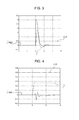
- FIGS 3 and 4 show two graphs of the response of vehicle handling enhancement system 10 in two different operating conditions.
- the Figure 3 graph relates to an operating condition in which vehicle 1 has a steer angle ⁇ but is not accelerating, which condition occurs when the vehicle is approaching a curve and the driver maintains a constant steer angle ⁇ .
- vehicle handling enhancement system 10 receives steer angle ⁇ >0 and, by means of computing block 12, immediately increases reference yaw acceleration ⁇ REF .
- the system regulates braking torque Cf to follow the reference yaw acceleration ⁇ REF pattern and so zero the difference between reference yaw acceleration ⁇ REF and measured actual yaw acceleration ⁇ .
- the Figure 4 graph relates to an operating condition in which the vehicle is accelerating round a bend.
- the vehicle control system described Besides being cheap to implement, by employing the safety system already on the vehicle, the vehicle control system described also has the advantage of allowing the driver to enhance vehicle performance to a greater degree with respect to known vehicle control systems.
- the vehicle control system may be variously adjusted, so the driver can choose the setting best suited to given driving conditions, and so obtain different performance levels of the same vehicle, depending on the chosen setting.
Description
- The present invention relates to a system for enhancing the cornering performance of a vehicle, in particular an automobile, controlled by a safety system.
- As is known, over the past few years, the automotive industry has become increasingly aware of the need to improve driving safety.
- Accordingly, safety systems have been devised, such as the Antilock Braking System, Electronic Stability Control System, Anti-Slip Regulation System, which are configured to intervene when a critical instability condition of the vehicle, e.g. when cornering, is determined.
- As is also known, in recent times, a demand has arisen among drivers of vehicles equipped with the above safety systems to enhance vehicle performance, in particular handling of the vehicle when cornering, to achieve a more personal high-performance, e.g. racing, driving mode.
- Accordingly, auxiliary control systems have been devised, such as the Active Differential and Rear Wheel Steering systems.
- Though efficient, auxiliary control systems of the above type have not met with much success in the vehicle control system market, on account of their high cost.
-
US5842754 discloses a vehicle turn control apparatus having an electronic control unit including a control start/end determination section in which two threshold values associated with the start timing of yaw moment control in the understeer and oversteer modes respectively. The determination section outputs a control beginning flag when the absolute value of required moment exceeds the absolute value of either threshold value. By providing such a control start condition, smooth yaw moment control can be achieved. Also, by setting the absolute value of threshold value in the oversteer mode at a value smaller than the absolute value of threshold value in the understeer mode, the yaw moment control in the oversteer mode is started at early timing. A restoration moment is quickly produced on the vehicle in the oversteer mode, thereby preventing spinning of the vehicle. - It is an object of the present invention to provide a safety-system-equipped vehicle control system, which is cheap to produce, and which at the same time provides for enhancing cornering performance of the vehicle to meet driver demand for enhanced driving performance.
- According to the present invention, there is provided a vehicle control system as defined in
Claim 1 and preferably, though not necessarily, in any one of the Claims depending directly or indirectly onClaim 1. - A non-limiting embodiment of the present invention will be described by way of example with reference to the accompanying drawings, in which:
-
Figure 1 shows a schematic of an automobile comprising a vehicle control system, equipped with a vehicle handling enhancement system, in accordance with the teachings of the present invention; -
Figure 2 shows a block diagram of theFigure 1 vehicle control system equipped with a vehicle handling enhancement system; -
Figures 3 and 4 show time graphs of yaw acceleration of the vehicle in respective vehicle operating conditions. -
Number 1 inFigure 1 indicates as a whole a vehicle, in particular an automobile, comprising four supportingwheels 2; abrake assembly 3 forbraking wheels 2 ofvehicle 1; and a vehicle control system 4 which controlsbrake assembly 3 to coordinate braking ofwheels 2 bybrake assembly 3. -
Brake assembly 3 is a known device and, not being the object of the present invention, is not described in detail, except to state that it comprises brake calipers (not shown), each associated with arespective wheel 2 and selectively activatable to exert braking action onwheel 2. - Vehicle control system 4 comprises a
safety system 7 designed to prevent locking of the vehicle wheels and loss of control of the vehicle when braking, and/or to intervene, when skidding, by adjusting output of the engine and/or differentially regulating a parameter controlling the braking force onwheels 2 ofvehicle 1, to automaticallyright vehicle 1. - More specifically, in the example shown,
safety system 7 preferably, though not necessarily, comprises an ABS (Antilock Braking System) and/or ESC (Electronic Stability Control) system, and/or any other similar type of vehicle safety system. - More specifically,
safety system 7 is configured to determine distribution of the braking torques Cfi to be applied bybrake assembly 3 to the brake calipers ofwheels 2 ofvehicle 1. - More specifically,
safety system 7 receives a parameter regulating the braking force, in particular the braking torque Cf, to be applied, when cornering, to the brake caliper of therear wheel 2 ofvehicle 1 on the inside of the curve travelled byvehicle 1. -
Safety system 7 supplies a number of vehicle parameters, some measured by sensors (not shown) onvehicle 1, and others obtained in known manner by specific processing. - More specifically,
safety system 7 supplies the following parameters : vehicle speed Vel measured along the longitudinal axis of the vehicle; actual yaw rate ψ̇ corresponding to the measured yaw rate of the vehicle; the driver-set steer angle δ of the front wheels ofvehicle 1; vehicle accelerator pedal operating speed ω, which is also used as an additional parameter by the system to conveniently strengthen the system and/or as a plausibility check and/or for safety reasons; steering speed δ̇ of the vehicle front wheels, which is also used as an additional parameter by the system to conveniently strengthen the system and/or as a plausibility check and/or for safety reasons; longitudinal vehicle acceleration ax, which is also used as an additional parameter by the system; and transverse vehicle acceleration ay, which is also used as an additional parameter by the system. -
Vehicle 1 also comprises a vehiclehandling enhancement system 10 designed to cooperate withsafety system 7 to allow the driver to "modify" the dynamic behaviour ofvehicle 1 when cornering. - Vehicle
handling enhancement system 10 is configured to calculate a reference yaw acceleration ψ̈REF as a function of the dynamic behaviour of the vehicle, and calculates a control parameter related to the braking force, more specifically the braking torque Cf, to be supplied tosafety system 7, on the basis of the difference between reference yaw acceleration ψ̈REF and the actual yaw acceleration ψ̈. - More specifically, vehicle
handling enhancement system 10 is configured to regulate the braking torque Cf to be exerted on the insiderear wheel 2 of vehicle, to zero the difference between reference yaw acceleration ψ̈REF and actual yaw acceleration ψ̈. - In other words, vehicle
handling enhancement system 10 provides for generating reference yaw acceleration ψ̈REF related to the dynamic cornering behaviour of the vehicle induced by the driver, and, in stable conditions, regulates the braking torque Cf of the insiderear wheel 2 ofvehicle 1 by means of a closed control loop configured to gradually zero the difference between reference yaw acceleration ψ̈REF and actual yaw acceleration ψ̈. - With reference to
Figure 2 , vehiclehandling enhancement system 10 substantially comprises : a differentiatingblock 11; acomputing block 12; areference generating block 13; and amain controller 14. - More specifically, differentiating
block 11 is configured to receive the actual yaw rate ψ̇ measured on the vehicle, and supplies the measured yaw acceleration ψ̈. - More specifically, differentiating
block 11 calculates measured yaw acceleration ψ̈ as follows:
-
Computing block 12 is configured to receive : longitudinal vehicle speed Vel; the driver-set steer angle δ of the front wheels ofvehicle 1; vehicle accelerator pedal operating speed ω; driver steering speed δ̇ of the front vehicle wheels; vehicle acceleration ax measured along the longitudinal vehicle axis; and vehicle acceleration ay along an axis crosswise to the longitudinal vehicle axis. - More specifically,
computing block 12 is configured to calculate a reference yaw rate ψ̇REF as a function of the dynamic behaviour ofvehicle 1. - With reference to the
Figure 2 example,computing block 12 processes longitudinal vehicle speed Vel and steer angle δ of the front wheels ofvehicle 1 to determine a reference yaw rateψ̇REF. - More specifically,
computing block 12 determines reference yaw rate ψ̇REF according to the equation :
where KUS is an understeer coefficient; L is the vehicle wheelbase; and τs is the steering ratio. -
Reference generating block 13 receives reference yaw rateψ̇REF, and differentiates it to supply reference yaw accelerationψ̈REF. - More specifically, reference generating 13 calculates reference yaw acceleration ψ̈REF according to the equation :

-
Main controller 14 receives the difference between actual yaw acceleration ψ̈ and reference yaw acceleration ψ̈REF, and accordingly generates the braking torque Cf to be applied to the brake caliper of the insiderear wheel 2 of the vehicle. - More specifically,
main controller 14 may preferably, though not necessarily, comprise a proportional-integral-derivative PID module configured to regulate braking torque Cf to zero the difference between actual yaw acceleration ψ̈ and reference yaw acceleration ψ̈REF. - As
regards computing block 12, it should be pointed out that the dynamic behaviour model represented by equation a) is based on two assumptions; firstly, that the vehicle is cornering; and secondly, that the vehicle is stable with no roll. If both are true, dynamic vehicle behaviour can be defined by understeering coefficient KUS according to the equation:
where ay is lateral acceleration, which can be calculated according to the equation:
- Substituting equation c) for ay in equation b) gives equation a) defining the mathematical model employed by
computing block 12. -
Figures 3 and 4 show two graphs of the response of vehiclehandling enhancement system 10 in two different operating conditions. - More specifically, the
Figure 3 graph relates to an operating condition in whichvehicle 1 has a steer angle δ but is not accelerating, which condition occurs when the vehicle is approaching a curve and the driver maintains a constant steer angle δ. - With reference to
Figure 3 , in the presence of a steer angle, vehiclehandling enhancement system 10 receives steer angle δ>0 and, by means ofcomputing block 12, immediately increases reference yaw accelerationψ̈REF. At this stage, the system regulates braking torque Cf to follow the reference yaw acceleration ψ̈REF pattern and so zero the difference between reference yaw acceleration ψ̈REF and measured actual yaw acceleration ψ̈. - The
Figure 4 graph relates to an operating condition in which the vehicle is accelerating round a bend. - Acceleration of the vehicle subjects it to yaw acceleration, whereas the reference imposes zero acceleration. This therefore creates a reference-measurement error which computing
block 12 uses and attempts to eliminate. - Besides being cheap to implement, by employing the safety system already on the vehicle, the vehicle control system described also has the advantage of allowing the driver to enhance vehicle performance to a greater degree with respect to known vehicle control systems.
- Moreover, the vehicle control system may be variously adjusted, so the driver can choose the setting best suited to given driving conditions, and so obtain different performance levels of the same vehicle, depending on the chosen setting.
- Clearly, changes may be made to the system described without, however, departing from the scope of the present invention as defined in the accompanying Claims.
Claims (7)
- A system (4) for controlling a vehicle (1) comprising a number of wheels (2), and a brake assembly (3) for exerting braking force on at least one wheel (2) on the basis of a number of control parameters (Cfi);
said system (4) comprising a safety system (7) configured to prevent locking of the vehicle wheels (2) and loss of control of the vehicle (1) when braking or skidding, by differentially regulating control parameters (Cfi) to automatically right vehicle (1); said safety system (7) being further configured to generate said control parameters (Cfi) as a function of a control quantity (Cf) associated with the braking force to be exerted on at least one of said wheels (2);
said system (4) being characterized by comprising a vehicle handling enhancement system (10) configured to cooperate with said safety system (7) to allow the driver to modify the dynamic behavior of vehicle (1) when cornering; said handling enhancement system (10) being configured to:- receive form said safety system (7) the actual yaw rate (ψ̇) measured on the vehicle, and differentiating actual yaw rate (ψ̇) to determine the actual yaw acceleration (ψ̈);- receive form said safety system (7) the longitudinal speed (ve1) and the steer angle (δ) of the vehicle (1);- calculate a reference vehicle yaw acceleration (ψ̈REF) on the basis of at least the longitudinal speed (vel) of said vehicle (1) and the steer angle (δ) of the vehicle (1);- adjust, when the vehicle is cornering and is in stable conditions with no roll, the control quantity (Cf) to be exerted on the inside rear wheel (2) of vehicle of the travelled curve, to zero the difference between reference yaw acceleration (ψ̈ REF) and actual yaw acceleration (ψ̈). - A system as claimed in Claim 1, wherein said vehicle handling enhancement system (10) is configured to determine said reference vehicle yaw acceleration (ψ̈REF) according to the equations:


where ψ̇ REF is the reference yaw rate; δ is the steer angle; KUS is an understeer coefficient; L is the vehicle wheelbase; τs is the steering ratio; and Vel is the longitudinal vehicle speed. - A system as claimed in Claim 1 or 2, wherein said vehicle handling enhancement system (10) comprises an ABS (Antilock Braking System) and/or an ESC (Electronic Stability Control) system.
- A system as claimed in any one of the foregoing Claims, wherein said vehicle handling enhancement system (10) comprises a differentiating block (11) configured to receive the actual yaw rate (ψ̇) measured on the vehicle, and to supply the measured yaw acceleration (ψ̈).
- A system as claimed in any one of the foregoing Claims, wherein said vehicle handling enhancement system (10) comprises a computing block (12) configured to calculate a reference yaw rate (ψ̇ REF) as a function of the dynamic behaviour of the vehicle (1).
- A system as claimed in any one of the foregoing Claims, wherein said vehicle handling enhancement system (10) comprises a main controller (14) which receives the difference between the actual yaw acceleration (ψ̈) and the reference vehicle yaw acceleration (ψ̈ REF), and generates said control quantity (Cf) as a function of said difference.
- A system as claimed in Claim 6, wherein said control quantity (Cf) corresponds to a braking torque to be applied to the inside rear wheel of the vehicle (1); said main controller (14) being configured to form, together with said safety system (7), a closed control loop for regulating said braking torque (Cf) to zero the difference between the actual yaw acceleration (ψ̈) and said reference vehicle yaw acceleration (ψ̈ REF).
Priority Applications (2)
| Application Number | Priority Date | Filing Date | Title |
|---|---|---|---|
| EP09425333.3A EP2289746B1 (en) | 2009-08-27 | 2009-08-27 | System for enhancing cornering performance of a vehicle controlled by a safety system |
| US12/859,855 US8442736B2 (en) | 2009-08-27 | 2010-08-20 | System for enhancing cornering performance of a vehicle controlled by a safety system |
Applications Claiming Priority (1)
| Application Number | Priority Date | Filing Date | Title |
|---|---|---|---|
| EP09425333.3A EP2289746B1 (en) | 2009-08-27 | 2009-08-27 | System for enhancing cornering performance of a vehicle controlled by a safety system |
Publications (2)
| Publication Number | Publication Date |
|---|---|
| EP2289746A1 EP2289746A1 (en) | 2011-03-02 |
| EP2289746B1 true EP2289746B1 (en) | 2015-07-22 |
Family
ID=41510710
Family Applications (1)
| Application Number | Title | Priority Date | Filing Date |
|---|---|---|---|
| EP09425333.3A Active EP2289746B1 (en) | 2009-08-27 | 2009-08-27 | System for enhancing cornering performance of a vehicle controlled by a safety system |
Country Status (2)
| Country | Link |
|---|---|
| US (1) | US8442736B2 (en) |
| EP (1) | EP2289746B1 (en) |
Families Citing this family (5)
| Publication number | Priority date | Publication date | Assignee | Title |
|---|---|---|---|---|
| DE102010027978A1 (en) * | 2010-04-20 | 2011-10-20 | Robert Bosch Gmbh | Driver assistance system and method for setting a driver assistance system |
| JP5736673B2 (en) * | 2010-06-07 | 2015-06-17 | 日産自動車株式会社 | Braking force coordination controller for compound brake |
| US20180170394A1 (en) * | 2016-12-16 | 2018-06-21 | Delphi Technologies, Inc. | Automated vehicle control with payload compensation |
| US10300897B2 (en) * | 2017-05-15 | 2019-05-28 | Goodrich Corporation | Brake load balance and runway centering techniques |
| CN113119947A (en) * | 2021-05-21 | 2021-07-16 | 前海七剑科技(深圳)有限公司 | Vehicle control method and device |
Family Cites Families (7)
| Publication number | Priority date | Publication date | Assignee | Title |
|---|---|---|---|---|
| JP2993400B2 (en) * | 1995-06-09 | 1999-12-20 | 三菱自動車工業株式会社 | Vehicle turning control device |
| JP3724845B2 (en) * | 1995-06-09 | 2005-12-07 | 本田技研工業株式会社 | Anti-lock brake control method for vehicle |
| DE10122654A1 (en) * | 2001-05-10 | 2002-12-05 | Bosch Gmbh Robert | Method and system for regulating the driving behavior of a vehicle |
| EP1562810B1 (en) * | 2002-11-22 | 2007-07-04 | DaimlerChrysler AG | Method and device for stabilising a semi-trailer |
| US6909959B2 (en) * | 2003-03-07 | 2005-06-21 | Stephen James Hallowell | Torque distribution systems and methods for wheeled vehicles |
| DE602005022823D1 (en) * | 2005-02-23 | 2010-09-23 | Ford Global Tech Llc | Method and device for yaw rate control of a vehicle |
| US7308353B2 (en) * | 2005-06-30 | 2007-12-11 | Gm Global Technology Operations, Inc. | Closed loop vehicle dynamic control for use with yaw rate controllers |
-
2009
- 2009-08-27 EP EP09425333.3A patent/EP2289746B1/en active Active
-
2010
- 2010-08-20 US US12/859,855 patent/US8442736B2/en active Active
Also Published As
| Publication number | Publication date |
|---|---|
| EP2289746A1 (en) | 2011-03-02 |
| US20110054757A1 (en) | 2011-03-03 |
| US8442736B2 (en) | 2013-05-14 |
Similar Documents
| Publication | Publication Date | Title |
|---|---|---|
| US10005455B2 (en) | Method in order to control vehicle behaviour | |
| US8548706B2 (en) | Device operable to control turning of vehicle | |
| EP2112053B1 (en) | Yaw stability control system | |
| US7761215B2 (en) | Device operable to control turning of vehicle using driving and braking force for understeering and oversteering | |
| US9020699B2 (en) | Method and braking system for influencing driving dynamics by means of braking and driving operations | |
| JP6844500B2 (en) | Vehicle behavior control device | |
| US8255122B2 (en) | Vehicle behavior control apparatus | |
| US20150314759A1 (en) | Vehicle movement dynamics control method | |
| JP2007008450A (en) | Automobile driving dynamics adjusting method | |
| US20070188020A1 (en) | Method for controlling a brake pressure | |
| CN102119097B (en) | Vehicle behavior control apparatus and vehicle behavior control method | |
| EP2289746B1 (en) | System for enhancing cornering performance of a vehicle controlled by a safety system | |
| US8204669B2 (en) | Method and device for regulating the driving dynamics of a vehicle | |
| JP4172361B2 (en) | Control device for electric power steering device | |
| JP5636825B2 (en) | Vehicle weight estimation device | |
| US8660750B2 (en) | System for enhancing cornering performance of a vehicle equipped with a stability control system | |
| JP4535178B2 (en) | Vehicle behavior control device | |
| JP4910361B2 (en) | Vehicle driving force control device | |
| JP4784741B2 (en) | Vehicle driving force control device | |
| CN111152781A (en) | Vehicle behavior stabilization system | |
| JP7103080B2 (en) | Vehicle control device | |
| JP2009185643A (en) | Behavior control device for vehicle | |
| JP4666025B2 (en) | Vehicle behavior control device | |
| JP5924245B2 (en) | Vehicle behavior control device |
Legal Events
| Date | Code | Title | Description |
|---|---|---|---|
| PUAI | Public reference made under article 153(3) epc to a published international application that has entered the european phase |
Free format text: ORIGINAL CODE: 0009012 |
|
| AK | Designated contracting states |
Kind code of ref document: A1 Designated state(s): AT BE BG CH CY CZ DE DK EE ES FI FR GB GR HR HU IE IS IT LI LT LU LV MC MK MT NL NO PL PT RO SE SI SK SM TR |
|
| AX | Request for extension of the european patent |
Extension state: AL BA RS |
|
| 17P | Request for examination filed |
Effective date: 20110902 |
|
| 17Q | First examination report despatched |
Effective date: 20120208 |
|
| GRAP | Despatch of communication of intention to grant a patent |
Free format text: ORIGINAL CODE: EPIDOSNIGR1 |
|
| INTG | Intention to grant announced |
Effective date: 20150213 |
|
| GRAS | Grant fee paid |
Free format text: ORIGINAL CODE: EPIDOSNIGR3 |
|
| GRAA | (expected) grant |
Free format text: ORIGINAL CODE: 0009210 |
|
| AK | Designated contracting states |
Kind code of ref document: B1 Designated state(s): AT BE BG CH CY CZ DE DK EE ES FI FR GB GR HR HU IE IS IT LI LT LU LV MC MK MT NL NO PL PT RO SE SI SK SM TR |
|
| REG | Reference to a national code |
Ref country code: GB Ref legal event code: FG4D |
|
| REG | Reference to a national code |
Ref country code: CH Ref legal event code: EP |
|
| REG | Reference to a national code |
Ref country code: IE Ref legal event code: FG4D |
|
| REG | Reference to a national code |
Ref country code: AT Ref legal event code: REF Ref document number: 737696 Country of ref document: AT Kind code of ref document: T Effective date: 20150815 |
|
| REG | Reference to a national code |
Ref country code: DE Ref legal event code: R096 Ref document number: 602009032325 Country of ref document: DE |
|
| REG | Reference to a national code |
Ref country code: AT Ref legal event code: MK05 Ref document number: 737696 Country of ref document: AT Kind code of ref document: T Effective date: 20150722 |
|
| REG | Reference to a national code |
Ref country code: LT Ref legal event code: MG4D |
|
| REG | Reference to a national code |
Ref country code: NL Ref legal event code: MP Effective date: 20150722 |
|
| PG25 | Lapsed in a contracting state [announced via postgrant information from national office to epo] |
Ref country code: NO Free format text: LAPSE BECAUSE OF FAILURE TO SUBMIT A TRANSLATION OF THE DESCRIPTION OR TO PAY THE FEE WITHIN THE PRESCRIBED TIME-LIMIT Effective date: 20151022 Ref country code: LT Free format text: LAPSE BECAUSE OF FAILURE TO SUBMIT A TRANSLATION OF THE DESCRIPTION OR TO PAY THE FEE WITHIN THE PRESCRIBED TIME-LIMIT Effective date: 20150722 Ref country code: LV Free format text: LAPSE BECAUSE OF FAILURE TO SUBMIT A TRANSLATION OF THE DESCRIPTION OR TO PAY THE FEE WITHIN THE PRESCRIBED TIME-LIMIT Effective date: 20150722 Ref country code: GR Free format text: LAPSE BECAUSE OF FAILURE TO SUBMIT A TRANSLATION OF THE DESCRIPTION OR TO PAY THE FEE WITHIN THE PRESCRIBED TIME-LIMIT Effective date: 20151023 Ref country code: FI Free format text: LAPSE BECAUSE OF FAILURE TO SUBMIT A TRANSLATION OF THE DESCRIPTION OR TO PAY THE FEE WITHIN THE PRESCRIBED TIME-LIMIT Effective date: 20150722 |
|
| PG25 | Lapsed in a contracting state [announced via postgrant information from national office to epo] |
Ref country code: PL Free format text: LAPSE BECAUSE OF FAILURE TO SUBMIT A TRANSLATION OF THE DESCRIPTION OR TO PAY THE FEE WITHIN THE PRESCRIBED TIME-LIMIT Effective date: 20150722 Ref country code: HR Free format text: LAPSE BECAUSE OF FAILURE TO SUBMIT A TRANSLATION OF THE DESCRIPTION OR TO PAY THE FEE WITHIN THE PRESCRIBED TIME-LIMIT Effective date: 20150722 Ref country code: ES Free format text: LAPSE BECAUSE OF FAILURE TO SUBMIT A TRANSLATION OF THE DESCRIPTION OR TO PAY THE FEE WITHIN THE PRESCRIBED TIME-LIMIT Effective date: 20150722 Ref country code: SE Free format text: LAPSE BECAUSE OF FAILURE TO SUBMIT A TRANSLATION OF THE DESCRIPTION OR TO PAY THE FEE WITHIN THE PRESCRIBED TIME-LIMIT Effective date: 20150722 Ref country code: PT Free format text: LAPSE BECAUSE OF FAILURE TO SUBMIT A TRANSLATION OF THE DESCRIPTION OR TO PAY THE FEE WITHIN THE PRESCRIBED TIME-LIMIT Effective date: 20151123 Ref country code: AT Free format text: LAPSE BECAUSE OF FAILURE TO SUBMIT A TRANSLATION OF THE DESCRIPTION OR TO PAY THE FEE WITHIN THE PRESCRIBED TIME-LIMIT Effective date: 20150722 Ref country code: IS Free format text: LAPSE BECAUSE OF FAILURE TO SUBMIT A TRANSLATION OF THE DESCRIPTION OR TO PAY THE FEE WITHIN THE PRESCRIBED TIME-LIMIT Effective date: 20151122 |
|
| REG | Reference to a national code |
Ref country code: CH Ref legal event code: PL |
|
| REG | Reference to a national code |
Ref country code: DE Ref legal event code: R097 Ref document number: 602009032325 Country of ref document: DE |
|
| PG25 | Lapsed in a contracting state [announced via postgrant information from national office to epo] |
Ref country code: SK Free format text: LAPSE BECAUSE OF FAILURE TO SUBMIT A TRANSLATION OF THE DESCRIPTION OR TO PAY THE FEE WITHIN THE PRESCRIBED TIME-LIMIT Effective date: 20150722 Ref country code: EE Free format text: LAPSE BECAUSE OF FAILURE TO SUBMIT A TRANSLATION OF THE DESCRIPTION OR TO PAY THE FEE WITHIN THE PRESCRIBED TIME-LIMIT Effective date: 20150722 Ref country code: CH Free format text: LAPSE BECAUSE OF NON-PAYMENT OF DUE FEES Effective date: 20150831 Ref country code: CZ Free format text: LAPSE BECAUSE OF FAILURE TO SUBMIT A TRANSLATION OF THE DESCRIPTION OR TO PAY THE FEE WITHIN THE PRESCRIBED TIME-LIMIT Effective date: 20150722 Ref country code: DK Free format text: LAPSE BECAUSE OF FAILURE TO SUBMIT A TRANSLATION OF THE DESCRIPTION OR TO PAY THE FEE WITHIN THE PRESCRIBED TIME-LIMIT Effective date: 20150722 Ref country code: MC Free format text: LAPSE BECAUSE OF FAILURE TO SUBMIT A TRANSLATION OF THE DESCRIPTION OR TO PAY THE FEE WITHIN THE PRESCRIBED TIME-LIMIT Effective date: 20150722 Ref country code: LI Free format text: LAPSE BECAUSE OF NON-PAYMENT OF DUE FEES Effective date: 20150831 |
|
| PLBE | No opposition filed within time limit |
Free format text: ORIGINAL CODE: 0009261 |
|
| STAA | Information on the status of an ep patent application or granted ep patent |
Free format text: STATUS: NO OPPOSITION FILED WITHIN TIME LIMIT |
|
| PG25 | Lapsed in a contracting state [announced via postgrant information from national office to epo] |
Ref country code: RO Free format text: LAPSE BECAUSE OF FAILURE TO SUBMIT A TRANSLATION OF THE DESCRIPTION OR TO PAY THE FEE WITHIN THE PRESCRIBED TIME-LIMIT Effective date: 20150722 |
|
| REG | Reference to a national code |
Ref country code: IE Ref legal event code: MM4A |
|
| 26N | No opposition filed |
Effective date: 20160425 |
|
| GBPC | Gb: european patent ceased through non-payment of renewal fee |
Effective date: 20151022 |
|
| PG25 | Lapsed in a contracting state [announced via postgrant information from national office to epo] |
Ref country code: IE Free format text: LAPSE BECAUSE OF NON-PAYMENT OF DUE FEES Effective date: 20150827 Ref country code: GB Free format text: LAPSE BECAUSE OF NON-PAYMENT OF DUE FEES Effective date: 20151022 |
|
| REG | Reference to a national code |
Ref country code: FR Ref legal event code: PLFP Year of fee payment: 8 |
|
| PG25 | Lapsed in a contracting state [announced via postgrant information from national office to epo] |
Ref country code: SI Free format text: LAPSE BECAUSE OF FAILURE TO SUBMIT A TRANSLATION OF THE DESCRIPTION OR TO PAY THE FEE WITHIN THE PRESCRIBED TIME-LIMIT Effective date: 20150722 |
|
| PG25 | Lapsed in a contracting state [announced via postgrant information from national office to epo] |
Ref country code: MT Free format text: LAPSE BECAUSE OF FAILURE TO SUBMIT A TRANSLATION OF THE DESCRIPTION OR TO PAY THE FEE WITHIN THE PRESCRIBED TIME-LIMIT Effective date: 20150722 |
|
| PG25 | Lapsed in a contracting state [announced via postgrant information from national office to epo] |
Ref country code: SM Free format text: LAPSE BECAUSE OF FAILURE TO SUBMIT A TRANSLATION OF THE DESCRIPTION OR TO PAY THE FEE WITHIN THE PRESCRIBED TIME-LIMIT Effective date: 20150722 Ref country code: BG Free format text: LAPSE BECAUSE OF FAILURE TO SUBMIT A TRANSLATION OF THE DESCRIPTION OR TO PAY THE FEE WITHIN THE PRESCRIBED TIME-LIMIT Effective date: 20150722 Ref country code: HU Free format text: LAPSE BECAUSE OF FAILURE TO SUBMIT A TRANSLATION OF THE DESCRIPTION OR TO PAY THE FEE WITHIN THE PRESCRIBED TIME-LIMIT; INVALID AB INITIO Effective date: 20090827 |
|
| PG25 | Lapsed in a contracting state [announced via postgrant information from national office to epo] |
Ref country code: CY Free format text: LAPSE BECAUSE OF FAILURE TO SUBMIT A TRANSLATION OF THE DESCRIPTION OR TO PAY THE FEE WITHIN THE PRESCRIBED TIME-LIMIT Effective date: 20150722 Ref country code: NL Free format text: LAPSE BECAUSE OF FAILURE TO SUBMIT A TRANSLATION OF THE DESCRIPTION OR TO PAY THE FEE WITHIN THE PRESCRIBED TIME-LIMIT Effective date: 20150722 |
|
| PG25 | Lapsed in a contracting state [announced via postgrant information from national office to epo] |
Ref country code: BE Free format text: LAPSE BECAUSE OF NON-PAYMENT OF DUE FEES Effective date: 20150831 |
|
| REG | Reference to a national code |
Ref country code: FR Ref legal event code: PLFP Year of fee payment: 9 |
|
| PG25 | Lapsed in a contracting state [announced via postgrant information from national office to epo] |
Ref country code: TR Free format text: LAPSE BECAUSE OF FAILURE TO SUBMIT A TRANSLATION OF THE DESCRIPTION OR TO PAY THE FEE WITHIN THE PRESCRIBED TIME-LIMIT Effective date: 20150722 |
|
| PG25 | Lapsed in a contracting state [announced via postgrant information from national office to epo] |
Ref country code: LU Free format text: LAPSE BECAUSE OF NON-PAYMENT OF DUE FEES Effective date: 20150827 |
|
| PG25 | Lapsed in a contracting state [announced via postgrant information from national office to epo] |
Ref country code: MK Free format text: LAPSE BECAUSE OF FAILURE TO SUBMIT A TRANSLATION OF THE DESCRIPTION OR TO PAY THE FEE WITHIN THE PRESCRIBED TIME-LIMIT Effective date: 20150722 |
|
| REG | Reference to a national code |
Ref country code: FR Ref legal event code: PLFP Year of fee payment: 10 |
|
| PGFP | Annual fee paid to national office [announced via postgrant information from national office to epo] |
Ref country code: IT Payment date: 20230720 Year of fee payment: 15 |
|
| PGFP | Annual fee paid to national office [announced via postgrant information from national office to epo] |
Ref country code: FR Payment date: 20230720 Year of fee payment: 15 Ref country code: DE Payment date: 20230720 Year of fee payment: 15 |