EP1483035B1 - Gas separation by combined pressure swing and displacement purge - Google Patents
Gas separation by combined pressure swing and displacement purge Download PDFInfo
- Publication number
- EP1483035B1 EP1483035B1 EP03743781A EP03743781A EP1483035B1 EP 1483035 B1 EP1483035 B1 EP 1483035B1 EP 03743781 A EP03743781 A EP 03743781A EP 03743781 A EP03743781 A EP 03743781A EP 1483035 B1 EP1483035 B1 EP 1483035B1
- Authority
- EP
- European Patent Office
- Prior art keywords
- component
- gas
- adsorber
- buffer
- purge
- Prior art date
- Legal status (The legal status is an assumption and is not a legal conclusion. Google has not performed a legal analysis and makes no representation as to the accuracy of the status listed.)
- Expired - Lifetime
Links
- 238000010926 purge Methods 0.000 title claims abstract description 103
- 238000006073 displacement reaction Methods 0.000 title claims abstract description 55
- 238000000926 separation method Methods 0.000 title claims abstract description 36
- 239000007789 gas Substances 0.000 claims abstract description 210
- 238000000034 method Methods 0.000 claims abstract description 56
- 239000000203 mixture Substances 0.000 claims abstract description 49
- CURLTUGMZLYLDI-UHFFFAOYSA-N Carbon dioxide Chemical compound O=C=O CURLTUGMZLYLDI-UHFFFAOYSA-N 0.000 claims abstract description 42
- 229910002092 carbon dioxide Inorganic materials 0.000 claims abstract description 21
- 239000001569 carbon dioxide Substances 0.000 claims abstract description 19
- 239000001257 hydrogen Substances 0.000 claims abstract description 14
- 229910052739 hydrogen Inorganic materials 0.000 claims abstract description 14
- IJGRMHOSHXDMSA-UHFFFAOYSA-N Atomic nitrogen Chemical compound N#N IJGRMHOSHXDMSA-UHFFFAOYSA-N 0.000 claims abstract description 10
- 229910052757 nitrogen Inorganic materials 0.000 claims abstract description 5
- 239000003463 adsorbent Substances 0.000 claims description 83
- 239000000463 material Substances 0.000 claims description 41
- 239000011800 void material Substances 0.000 claims description 6
- 238000004064 recycling Methods 0.000 claims description 4
- 125000004435 hydrogen atom Chemical group [H]* 0.000 claims 1
- UFHFLCQGNIYNRP-UHFFFAOYSA-N Hydrogen Chemical compound [H][H] UFHFLCQGNIYNRP-UHFFFAOYSA-N 0.000 abstract description 13
- 230000000274 adsorptive effect Effects 0.000 abstract description 6
- QVGXLLKOCUKJST-UHFFFAOYSA-N atomic oxygen Chemical compound [O] QVGXLLKOCUKJST-UHFFFAOYSA-N 0.000 abstract description 6
- 238000012864 cross contamination Methods 0.000 abstract description 6
- 239000001301 oxygen Substances 0.000 abstract description 6
- 229910052760 oxygen Inorganic materials 0.000 abstract description 6
- 238000001179 sorption measurement Methods 0.000 description 24
- 230000008929 regeneration Effects 0.000 description 15
- 238000011069 regeneration method Methods 0.000 description 15
- XLYOFNOQVPJJNP-UHFFFAOYSA-N water Substances O XLYOFNOQVPJJNP-UHFFFAOYSA-N 0.000 description 14
- 238000002485 combustion reaction Methods 0.000 description 9
- 125000006850 spacer group Chemical group 0.000 description 9
- 239000010457 zeolite Substances 0.000 description 9
- 239000012530 fluid Substances 0.000 description 8
- 238000011084 recovery Methods 0.000 description 8
- 238000010992 reflux Methods 0.000 description 8
- 239000000446 fuel Substances 0.000 description 7
- 239000000758 substrate Substances 0.000 description 7
- UGFAIRIUMAVXCW-UHFFFAOYSA-N Carbon monoxide Chemical compound [O+]#[C-] UGFAIRIUMAVXCW-UHFFFAOYSA-N 0.000 description 5
- 229910021536 Zeolite Inorganic materials 0.000 description 5
- PNEYBMLMFCGWSK-UHFFFAOYSA-N aluminium oxide Inorganic materials [O-2].[O-2].[O-2].[Al+3].[Al+3] PNEYBMLMFCGWSK-UHFFFAOYSA-N 0.000 description 5
- 229910052751 metal Inorganic materials 0.000 description 5
- 239000002184 metal Substances 0.000 description 5
- HNPSIPDUKPIQMN-UHFFFAOYSA-N dioxosilane;oxo(oxoalumanyloxy)alumane Chemical compound O=[Si]=O.O=[Al]O[Al]=O HNPSIPDUKPIQMN-UHFFFAOYSA-N 0.000 description 4
- 239000003546 flue gas Substances 0.000 description 4
- 239000011888 foil Substances 0.000 description 4
- BWHMMNNQKKPAPP-UHFFFAOYSA-L potassium carbonate Chemical compound [K+].[K+].[O-]C([O-])=O BWHMMNNQKKPAPP-UHFFFAOYSA-L 0.000 description 4
- 230000007704 transition Effects 0.000 description 4
- OKTJSMMVPCPJKN-UHFFFAOYSA-N Carbon Chemical compound [C] OKTJSMMVPCPJKN-UHFFFAOYSA-N 0.000 description 3
- OKKJLVBELUTLKV-UHFFFAOYSA-N Methanol Chemical compound OC OKKJLVBELUTLKV-UHFFFAOYSA-N 0.000 description 3
- 229910052784 alkaline earth metal Inorganic materials 0.000 description 3
- 210000004027 cell Anatomy 0.000 description 3
- 238000003795 desorption Methods 0.000 description 3
- 239000011152 fibreglass Substances 0.000 description 3
- 238000010438 heat treatment Methods 0.000 description 3
- 238000002156 mixing Methods 0.000 description 3
- 238000012545 processing Methods 0.000 description 3
- 238000007789 sealing Methods 0.000 description 3
- 238000012546 transfer Methods 0.000 description 3
- 150000001342 alkaline earth metals Chemical class 0.000 description 2
- 239000011230 binding agent Substances 0.000 description 2
- 229910052799 carbon Inorganic materials 0.000 description 2
- 238000004891 communication Methods 0.000 description 2
- 230000006835 compression Effects 0.000 description 2
- 238000007906 compression Methods 0.000 description 2
- 239000000470 constituent Substances 0.000 description 2
- 238000011109 contamination Methods 0.000 description 2
- 125000004122 cyclic group Chemical group 0.000 description 2
- 238000005516 engineering process Methods 0.000 description 2
- 230000002708 enhancing effect Effects 0.000 description 2
- 230000002209 hydrophobic effect Effects 0.000 description 2
- 239000011261 inert gas Substances 0.000 description 2
- 239000007800 oxidant agent Substances 0.000 description 2
- 230000001590 oxidative effect Effects 0.000 description 2
- 238000005192 partition Methods 0.000 description 2
- 229910000027 potassium carbonate Inorganic materials 0.000 description 2
- 238000010248 power generation Methods 0.000 description 2
- QTBSBXVTEAMEQO-UHFFFAOYSA-M Acetate Chemical compound CC([O-])=O QTBSBXVTEAMEQO-UHFFFAOYSA-M 0.000 description 1
- BVKZGUZCCUSVTD-UHFFFAOYSA-M Bicarbonate Chemical compound OC([O-])=O BVKZGUZCCUSVTD-UHFFFAOYSA-M 0.000 description 1
- 239000004215 Carbon black (E152) Substances 0.000 description 1
- BVKZGUZCCUSVTD-UHFFFAOYSA-L Carbonate Chemical compound [O-]C([O-])=O BVKZGUZCCUSVTD-UHFFFAOYSA-L 0.000 description 1
- VMQMZMRVKUZKQL-UHFFFAOYSA-N Cu+ Chemical compound [Cu+] VMQMZMRVKUZKQL-UHFFFAOYSA-N 0.000 description 1
- 229910002651 NO3 Inorganic materials 0.000 description 1
- NHNBFGGVMKEFGY-UHFFFAOYSA-N Nitrate Chemical compound [O-][N+]([O-])=O NHNBFGGVMKEFGY-UHFFFAOYSA-N 0.000 description 1
- 229910019142 PO4 Inorganic materials 0.000 description 1
- VYPSYNLAJGMNEJ-UHFFFAOYSA-N Silicium dioxide Chemical compound O=[Si]=O VYPSYNLAJGMNEJ-UHFFFAOYSA-N 0.000 description 1
- 239000003513 alkali Substances 0.000 description 1
- 229910052783 alkali metal Inorganic materials 0.000 description 1
- 150000001340 alkali metals Chemical class 0.000 description 1
- 239000004411 aluminium Substances 0.000 description 1
- 229910052782 aluminium Inorganic materials 0.000 description 1
- XAGFODPZIPBFFR-UHFFFAOYSA-N aluminium Chemical compound [Al] XAGFODPZIPBFFR-UHFFFAOYSA-N 0.000 description 1
- 238000013459 approach Methods 0.000 description 1
- 230000000712 assembly Effects 0.000 description 1
- 238000000429 assembly Methods 0.000 description 1
- 229910052788 barium Inorganic materials 0.000 description 1
- 235000021170 buffet Nutrition 0.000 description 1
- 229910052792 caesium Inorganic materials 0.000 description 1
- 229910052791 calcium Inorganic materials 0.000 description 1
- 229910002091 carbon monoxide Inorganic materials 0.000 description 1
- 230000003197 catalytic effect Effects 0.000 description 1
- 150000001768 cations Chemical class 0.000 description 1
- 210000002421 cell wall Anatomy 0.000 description 1
- 239000000919 ceramic Substances 0.000 description 1
- 238000006243 chemical reaction Methods 0.000 description 1
- 239000011248 coating agent Substances 0.000 description 1
- 238000000576 coating method Methods 0.000 description 1
- 239000002131 composite material Substances 0.000 description 1
- 150000001875 compounds Chemical class 0.000 description 1
- 238000010276 construction Methods 0.000 description 1
- 238000001816 cooling Methods 0.000 description 1
- 229910052878 cordierite Inorganic materials 0.000 description 1
- 239000013078 crystal Substances 0.000 description 1
- 239000002274 desiccant Substances 0.000 description 1
- GDVKFRBCXAPAQJ-UHFFFAOYSA-A dialuminum;hexamagnesium;carbonate;hexadecahydroxide Chemical compound [OH-].[OH-].[OH-].[OH-].[OH-].[OH-].[OH-].[OH-].[OH-].[OH-].[OH-].[OH-].[OH-].[OH-].[OH-].[OH-].[Mg+2].[Mg+2].[Mg+2].[Mg+2].[Mg+2].[Mg+2].[Al+3].[Al+3].[O-]C([O-])=O GDVKFRBCXAPAQJ-UHFFFAOYSA-A 0.000 description 1
- 238000007865 diluting Methods 0.000 description 1
- JSKIRARMQDRGJZ-UHFFFAOYSA-N dimagnesium dioxido-bis[(1-oxido-3-oxo-2,4,6,8,9-pentaoxa-1,3-disila-5,7-dialuminabicyclo[3.3.1]nonan-7-yl)oxy]silane Chemical compound [Mg++].[Mg++].[O-][Si]([O-])(O[Al]1O[Al]2O[Si](=O)O[Si]([O-])(O1)O2)O[Al]1O[Al]2O[Si](=O)O[Si]([O-])(O1)O2 JSKIRARMQDRGJZ-UHFFFAOYSA-N 0.000 description 1
- 239000006185 dispersion Substances 0.000 description 1
- 238000011143 downstream manufacturing Methods 0.000 description 1
- 230000009977 dual effect Effects 0.000 description 1
- 238000004049 embossing Methods 0.000 description 1
- 239000004744 fabric Substances 0.000 description 1
- 238000011049 filling Methods 0.000 description 1
- 238000002309 gasification Methods 0.000 description 1
- 239000000499 gel Substances 0.000 description 1
- 239000003365 glass fiber Substances 0.000 description 1
- 229930195733 hydrocarbon Natural products 0.000 description 1
- 150000002430 hydrocarbons Chemical class 0.000 description 1
- 229910001701 hydrotalcite Inorganic materials 0.000 description 1
- 229960001545 hydrotalcite Drugs 0.000 description 1
- XLYOFNOQVPJJNP-UHFFFAOYSA-M hydroxide Chemical compound [OH-] XLYOFNOQVPJJNP-UHFFFAOYSA-M 0.000 description 1
- 230000000977 initiatory effect Effects 0.000 description 1
- 229910052744 lithium Inorganic materials 0.000 description 1
- 238000011068 loading method Methods 0.000 description 1
- -1 organic acid salt compound Chemical class 0.000 description 1
- 238000012856 packing Methods 0.000 description 1
- NBIIXXVUZAFLBC-UHFFFAOYSA-K phosphate Chemical compound [O-]P([O-])([O-])=O NBIIXXVUZAFLBC-UHFFFAOYSA-K 0.000 description 1
- 239000010452 phosphate Substances 0.000 description 1
- 229910052700 potassium Inorganic materials 0.000 description 1
- 238000007639 printing Methods 0.000 description 1
- 238000000746 purification Methods 0.000 description 1
- 230000001172 regenerating effect Effects 0.000 description 1
- 230000001105 regulatory effect Effects 0.000 description 1
- 229910052701 rubidium Inorganic materials 0.000 description 1
- 239000000741 silica gel Substances 0.000 description 1
- 229910002027 silica gel Inorganic materials 0.000 description 1
- 239000002002 slurry Substances 0.000 description 1
- 229910052708 sodium Inorganic materials 0.000 description 1
- 239000007787 solid Substances 0.000 description 1
- 229910001220 stainless steel Inorganic materials 0.000 description 1
- 239000010935 stainless steel Substances 0.000 description 1
- 238000000629 steam reforming Methods 0.000 description 1
- 229910052712 strontium Inorganic materials 0.000 description 1
- 238000004804 winding Methods 0.000 description 1
Images


Classifications
-
- B—PERFORMING OPERATIONS; TRANSPORTING
- B01—PHYSICAL OR CHEMICAL PROCESSES OR APPARATUS IN GENERAL
- B01D—SEPARATION
- B01D53/00—Separation of gases or vapours; Recovering vapours of volatile solvents from gases; Chemical or biological purification of waste gases, e.g. engine exhaust gases, smoke, fumes, flue gases, aerosols
- B01D53/02—Separation of gases or vapours; Recovering vapours of volatile solvents from gases; Chemical or biological purification of waste gases, e.g. engine exhaust gases, smoke, fumes, flue gases, aerosols by adsorption, e.g. preparative gas chromatography
- B01D53/06—Separation of gases or vapours; Recovering vapours of volatile solvents from gases; Chemical or biological purification of waste gases, e.g. engine exhaust gases, smoke, fumes, flue gases, aerosols by adsorption, e.g. preparative gas chromatography with moving adsorbents, e.g. rotating beds
-
- B—PERFORMING OPERATIONS; TRANSPORTING
- B01—PHYSICAL OR CHEMICAL PROCESSES OR APPARATUS IN GENERAL
- B01D—SEPARATION
- B01D53/00—Separation of gases or vapours; Recovering vapours of volatile solvents from gases; Chemical or biological purification of waste gases, e.g. engine exhaust gases, smoke, fumes, flue gases, aerosols
- B01D53/02—Separation of gases or vapours; Recovering vapours of volatile solvents from gases; Chemical or biological purification of waste gases, e.g. engine exhaust gases, smoke, fumes, flue gases, aerosols by adsorption, e.g. preparative gas chromatography
- B01D53/04—Separation of gases or vapours; Recovering vapours of volatile solvents from gases; Chemical or biological purification of waste gases, e.g. engine exhaust gases, smoke, fumes, flue gases, aerosols by adsorption, e.g. preparative gas chromatography with stationary adsorbents
- B01D53/047—Pressure swing adsorption
-
- B—PERFORMING OPERATIONS; TRANSPORTING
- B01—PHYSICAL OR CHEMICAL PROCESSES OR APPARATUS IN GENERAL
- B01D—SEPARATION
- B01D2256/00—Main component in the product gas stream after treatment
- B01D2256/16—Hydrogen
-
- B—PERFORMING OPERATIONS; TRANSPORTING
- B01—PHYSICAL OR CHEMICAL PROCESSES OR APPARATUS IN GENERAL
- B01D—SEPARATION
- B01D2257/00—Components to be removed
- B01D2257/50—Carbon oxides
- B01D2257/504—Carbon dioxide
-
- B—PERFORMING OPERATIONS; TRANSPORTING
- B01—PHYSICAL OR CHEMICAL PROCESSES OR APPARATUS IN GENERAL
- B01D—SEPARATION
- B01D2259/00—Type of treatment
- B01D2259/40—Further details for adsorption processes and devices
- B01D2259/40011—Methods relating to the process cycle in pressure or temperature swing adsorption
- B01D2259/40043—Purging
- B01D2259/4005—Nature of purge gas
- B01D2259/40056—Gases other than recycled product or process gas
-
- B—PERFORMING OPERATIONS; TRANSPORTING
- B01—PHYSICAL OR CHEMICAL PROCESSES OR APPARATUS IN GENERAL
- B01D—SEPARATION
- B01D53/00—Separation of gases or vapours; Recovering vapours of volatile solvents from gases; Chemical or biological purification of waste gases, e.g. engine exhaust gases, smoke, fumes, flue gases, aerosols
- B01D53/02—Separation of gases or vapours; Recovering vapours of volatile solvents from gases; Chemical or biological purification of waste gases, e.g. engine exhaust gases, smoke, fumes, flue gases, aerosols by adsorption, e.g. preparative gas chromatography
- B01D53/04—Separation of gases or vapours; Recovering vapours of volatile solvents from gases; Chemical or biological purification of waste gases, e.g. engine exhaust gases, smoke, fumes, flue gases, aerosols by adsorption, e.g. preparative gas chromatography with stationary adsorbents
- B01D53/0407—Constructional details of adsorbing systems
- B01D53/0431—Beds with radial gas flow
-
- B—PERFORMING OPERATIONS; TRANSPORTING
- B01—PHYSICAL OR CHEMICAL PROCESSES OR APPARATUS IN GENERAL
- B01D—SEPARATION
- B01D53/00—Separation of gases or vapours; Recovering vapours of volatile solvents from gases; Chemical or biological purification of waste gases, e.g. engine exhaust gases, smoke, fumes, flue gases, aerosols
- B01D53/02—Separation of gases or vapours; Recovering vapours of volatile solvents from gases; Chemical or biological purification of waste gases, e.g. engine exhaust gases, smoke, fumes, flue gases, aerosols by adsorption, e.g. preparative gas chromatography
- B01D53/04—Separation of gases or vapours; Recovering vapours of volatile solvents from gases; Chemical or biological purification of waste gases, e.g. engine exhaust gases, smoke, fumes, flue gases, aerosols by adsorption, e.g. preparative gas chromatography with stationary adsorbents
- B01D53/0462—Temperature swing adsorption
-
- Y—GENERAL TAGGING OF NEW TECHNOLOGICAL DEVELOPMENTS; GENERAL TAGGING OF CROSS-SECTIONAL TECHNOLOGIES SPANNING OVER SEVERAL SECTIONS OF THE IPC; TECHNICAL SUBJECTS COVERED BY FORMER USPC CROSS-REFERENCE ART COLLECTIONS [XRACs] AND DIGESTS
- Y02—TECHNOLOGIES OR APPLICATIONS FOR MITIGATION OR ADAPTATION AGAINST CLIMATE CHANGE
- Y02C—CAPTURE, STORAGE, SEQUESTRATION OR DISPOSAL OF GREENHOUSE GASES [GHG]
- Y02C20/00—Capture or disposal of greenhouse gases
- Y02C20/40—Capture or disposal of greenhouse gases of CO2
Definitions
- This application is related to adsorptive gas separation methods, particularly rotary adsorptive gas separation methods, and QuestAir Technologies' related patents and patent applications, including Nos 6,406,523 , 09/808,715 , 10/039,940 , and 60/351,798 .
- an adsorbent material over which component B is more readily adsorbed and component A is less readily adsorbed may be provided, as is disclosed in the prior art.
- the adsorbent material is typically arranged to contact flow channels in adsorbers or adsorbent beds.
- Regeneration may be achieved by alternative strategies of pressure swing, displacement purge, thermal swing, or combinations thereof. It has also been claimed that regeneration of an electrically conductive (for example carbon-based) adsorbent material loaded with an adsorbed gas (for example carbon dioxide) may be achieved by applying an electric current in so-called electric swing adsorption.
- electrically conductive for example carbon-based
- an adsorbed gas for example carbon dioxide
- the total pressure of the gas contacting the adsorber is reduced (pressure swing) following the feed step, thus reducing the partial pressure of component B contacting the adsorbent, and desorbing component B to be exhausted by purging with a reflux fraction of already enriched component A.
- the total pressure of the gas mixture in the adsorber is elevated while the gas flow in the adsorber is directed from the first end to the second end thereof, while the total pressure is reduced in the regeneration step while the gas flow in the adsorber is directed from the second end back to the first end.
- a "light” product (a gas fraction depleted in the more readily adsorbed component and enriched in the less readily adsorbed component A) is delivered from the second end of the adsorber, and a “heavy” product (a gas fraction enriched in the more strongly adsorbed component B) is exhausted from the first end of the adsorber.
- the total pressure may be kept approximately constant in the regeneration step, while component B is desorbed by a third preferably less readily adsorbed component C, which was not part of the feed gas mixture, with component C introduced in reverse flow from the second end back to the first end of the adsorbers (displacement purge), thus reducing the partial pressure of component B contacting the adsorbent, and exhausting displaced component B from the first end of the adsorbers.
- a first or "light” product (a gas fraction depleted in the more readily adsorbed component B and enriched in the less readily adsorbed component A) is delivered from the second end of the adsorber, and a “heavy” product (a gas mixture including the more strongly adsorbed component B and the displacement component C) is exhausted from the first end of the adsorber.
- Regeneration may also be achieved by cyclically raising the temperature (temperature swing) of the adsorbent so as to reduce the adsorptive affinity for all gas species, resulting in desorption of component B which can then be purged in reverse flow by a purge stream either as a reflux of previously enriched component A or by displacement purge with a component C.
- Thermal swing adsorption requires bulk heating and cooling of the adsorbent on a cyclic basis, so has been generally limited to relatively low cycle frequencies in the prior art.
- the heating step may be achieved by heating the purge stream before admission to the second end of the adsorbers.
- displacement purge may be combined, so that a displacement purge regeneration step is achieved at a lower total pressure than the feed pressure.
- thermal swing may be combined with pressure swing and/or displacement purge regeneration strategies.
- displacement purge processes in the present context is that the displacement purge stream is externally provided and includes a component C that is not contained in the feed gas mixture to be separated, unlike conventional PSA or TSA processes where the purge stream is typically obtained internally as a fraction of the feed gas mixture undergoing separation.
- a method of displacement purge gas separation using as purge gas a gas not present in the gas mixture to be separated is disclosed in US4077779 to Sircar et al. .
- PSA is widely applied in hydrogen purification (e.g. from syngas generated by steam reforming or gasification of a hydrocarbon feedstock, after water gas shifting to minimize carbon monoxide concentration), with components A and B representing hydrogen and carbon dioxide.
- displacement purge using air or any oxygen-containing gas with oxygen appearing as a component C
- would in the prior art have been impracticable or at least impractical, owing to the hazards of cross-contamination between hydrogen and oxygen.
- the present invention is concerned with adsorptive separation of a first gas mixture containing less readily adsorbed first component (or fraction) A and more readily adsorbed second component (or fraction) B, with adsorber regeneration achieved by displacement purge, either alone or combination with pressure swing or thermal swing regeneration techniques.
- the displacement purge stream includes a preferably less readily adsorbed than B third component (or fraction) C which will be mixed with component B in the regeneration step
- a particular requirement may be to avoid or strictly minimise any mixing between components A and C in externally delivered or discharged gas streams. This requirement may arise in important applications where components A and C are incompatible, for example when components A and C are mutually chemically reactive, as when component A is a combustible fuel and component C is an oxidant. Other applications also are contemplated where component C may act detrimentally to a system for A in a downstream process, or vice versa.
- a first gas mixture including components A and B is to be separated so that a first product of the separation is enriched in component A, while component B is mixed with a third gas component C contained in a displacement purge stream to form a second gas mixture including components B and C, and preferably with provision to prevent cross contamination of component C into the first product containing component A, or of component A into the second gas mixture containing component C.
- Component C may be a major or minor constituent of the displacement purge gas stream.
- An apparatus used in a process according to an aspect of the present invention includes a co-operating set of N adsorbers (where N is an integer and is greater or equal to two), each adsorber having a flow path between first and second ends of the adsorber, and the flow path contacting an adsorbent material within the adsorber, with component B being more readily adsorbed relative to components A and C which are less readily adsorbed by the adsorbent material
- the adsorbers may be subjected to a cyclic adsorption process with process steps as set forth below, with a cycle period I and with the N adsorbers sequentially undergoing the steps of the cycle sequentially in staggered phase so that the process is substantially continuous.
- the process for each adsorber includes a feed step in which the first gas mixture is admitted at a first total pressure to a first end of the adsorber, while a first or "light" product gas enriched in component A is delivered from a second end of the adsorber as component B is preferentially adsorbed on the adsorbent contacting the flow channel(s) of the flow path within the adsorber
- the process also includes a displacement purge step in which displacement purge gas containing component C is admitted to one end of the adsorbed, while a second gas mixture (or “heavy” product gas) is delivered at a second total pressure from the other end of the adsorbers as component B desorbs from the adsorbent.
- the first and second pressures are substantially similar.
- the temperatures of the components may vary, such as component C being at a higher temperature than other components, so as to obtain a temperature swing component for the separation process.
- the temperature of the first product gas and second gas mixture is varied, such variations may be employed to increase the overall efficiency of the separation process.
- a first "buffer” step is performed in the disclosed process, in order to remove interstitial and adsorbed component A accumulated in the adsorber from the previous feed step, so as to avoid contamination of the second gas mixture (containing components B and C) to be produced in the imminent displacement purge step by component A.
- a second "buffer” step is performed in the disclosed process, in order to remove interstitial and adsorbed component C accumulated in the adsorber from the previous purge step, so as to avoid contamination of the first product gas to be produced in the following feed step by component C.
- the buffer steps according to the present aspect of the disclosure may be accomplished in several ways, including applications of the displacement purge principle by introducing a buffer sweep stream, optionally assisted by reducing the total pressure (e.g. by a modest vacuum) or by varying the temperature of the buffer sweep stream during the buffer steps, such as by reducing the temperature of the buffer gas relative to the feed and or purge gases.
- each buffer step will generate an exhaust stream, in which there may be some admixture of components A and C; and such buffer step exhaust streams may be subjected to further processing (such as by combustion to eliminate any unreacted mixture of A and C) for disposal.
- Buffer sweep gas to achieve displacement purge in the buffer steps may be provided as any less readily adsorbed gas stream.
- the first buffer sweep gas for a first buffer step preferably should not contain unbound component A
- the second buffer sweep gas for a second buffer step preferably should not contain unbound component C.
- the first buffer sweep gas may be or may contain displacement purge gas containing component C.
- the second buffer sweep gas may be or may contain first gas mixture containing component A.
- the buffer sweep gas for either buffer step may be selected to be an inert gas, which may be flue gas recycled from combustion of the buffer sweep gas under combustion conditions for each stream such that A is removed from sweep gas for a first buffer step, and C is removed from sweep gas for a second buffer step Alternatively, any other available less adsorbed gas not containing A or C may be used as a buffer sweep gas. For higher temperature applications, steam may be used as buffer sweep gas.
- the total pressure may be reduced (e.g. below the second pressure at which the displacement purge step is conducted) during the buffer steps to assist the removal of components A 01 C to be purged, and also to avoid any leakage (external to the adsorbers) of components A or C between process steps preceding and following each buffer step.
- desorbing component B may assist the purging of component A during that first buffer step
- a minor pressure swing to reduce the total pressure during buffer steps, by a modest level of vacuum if the second pressure is substantially atmospheric, may be used to enhance the reliability of the buffer steps, independently of whether a larger pressure swing is applied to assist the enrichment of component A
- a minor temperature swing may be implemented during buffer steps to assist in purging of the relevant component, and to thereby enhance the reliability of the buffer step, or alternatively to enhance the efficiency of the following adsorption or desorption step.
- the process may include additional steps as provided in well-known pressure swing adsorption processes for the depressurization of the adsorber after a feed step and before the first buffer step, and for repressurization of the adsorber after the second buffer step and before the next feed step.
- Depressurization steps may include cocurrent and/or countercurrent blowdown steps
- Repressurization steps may include backfill and feed pressurisation steps.
- Depressurization and repressurization steps may be achieved by single or plural pressure equalization steps performed between out-of-phase adsorbers by providing fluid communication between the first or second ends of adsorbers undergoing a pressure equalization step.
- any of the steps known for PSA and VPSA processes may be incorporated in the present process, which is characterized by the first and second buffer steps respectively just before and just after the displacement purge step
- a purge step using light product gas or cocurrent blowdown gas as purge gas may be conducted in addition to (and before or after) the displacement purge step.
- components A and C and any buffer sweep component D
- the number N of adsorbers be relatively large with each adsorber thus having a small inventory of adsorbent material, so that the buffer steps may occupy only a small fraction of the cycle period T.
- An apparatus embodiment includes a first valve means communicating to the first end and a second valve means communicating to the second end of each adsorber, so as to perform in sequence for each adsorber the complete cycle of the feed step, any depressurization steps, the first buffer step, the displacement purge step, the second buffer step, and any repressurization steps.
- rotary distributor valves are used as the first and second valve means.
- N adsorbers are preferably mounted as an array in a rotor engaged in fluid sealing contact on first and second valve faces with a stator.
- the gas separation apparatus of such an embodiment may then be referred to as a rotary adsorption module ("RAM").
- the rotor of a rotary adsorption module embodiment for use in the disclosed systems and processes includes a plurality of flow paths for receiving adsorbent material therein for preferentially adsorbing a first gas component in the flow paths relative to a second gas component.
- the gas separation system also may include compression machinery coupled to the rotary module for facilitating gas flow through the flow paths for separating the first gas component from the second gas component.
- the stator includes a first stator valve surface, a second stator valve surface, and plurality of function compartments opening into the stator valve surfaces.
- the function compartments include a gas feed compartment, and a light gas component exit compartment, and a buffer gas compartment.
- Light gas refers to withdrawn gas enriched in the second, less readily adsorbed component, which is typically withdrawn from the second ends of adsorbers via the second valve means.
- feed gas mixture may enter the adsorbent beds at the second end of the adsorbers via the second valve means, and light product gas may be withdrawn at the first end.
- any buffer or purge steps incorporated in such processes may be performed in either direction by admitting buffer or purge gas to either the first or second end of an adsorber.
- the function compartments may additionally include light reflux exit and return or other compartments to conduct light reflux, blowdown, pressurization or other gas flows related to the pressure swing component of the gas separation process to and from the adsorbers. Any such gas flows, in addition to product, buffer or purge gas flows may also be transferred from one adsorber to another, for flow though the receiving adsorber in either direction, by means of fluid connection means extending between the respective function compartments opening into the first and second stator valve faces.
- Such inter-adsorber transfer of gas flows may be utilized for example to recycle buffer gas flows between adsorbers to effectively enhance recovery of product gas components (A and B) by capturing product flows expelled from the adsorbers at the onset of a buffer step (instead of exhausting those product flows to the atmosphere), and to reduce the volume of buffer gas required to perform the buffer steps.
- recycling of buffer gas flows expelled at the onset of subsequent feed or purge steps in some embodiments of the presently disclosed processes enables the reduction of residual buffer gas remaining in adsorbers following a buffer step that may be delivered in product gas flows (containing product components A or B), thereby increasing the purity of product gas flows, and reducing any buildup of buffer gas component in cases where product gas components may be recycled through downstream systems or processes.
- the rotary adsorption module may itself operate at an elevated working temperature.
- the operating temperature of the adsorbers may range from approximately ambient temperature to an elevated temperature up to about 450°C, as may be facilitated by recuperative or regenerative heat exchange between the feed gas mixture and the displacement purge and/or buffer streams.
- the rotary adsorption module may be operated to support a temperature gradient along the length of the flow channels, so that for example the temperature at the first end of the adsorbers is higher than the temperature at the second end of the adsorbers.
- "operating temperature of the adsorbers" denotes the temperature of a gas flowing through the adsorbers and/or the temperature of the adsorber beds.
- a rotary adsorption module is provided that is adapted to enable separation of a feed gas mixture containing weakly adsorbed component A and relatively strongly adsorbed component B, and additionally another component E which is similarly adsorbed, or even more strongly adsorbed than component B, where it is desired to deliver enriched component A in combination with component E, and separate from a product stream including component B.
- the rotary adsorption module includes a rotor and stator, and associated function compartments, as in the previous module embodiment described above, and additionally includes a second separate set of adsorbers in the rotor module, and associated second separate set of function compartments opening into the stator valve surface, including at least a feed gas compartment, and product gas exit compartment.
- the adsorbent material in the second set of adsorbers is chosen to preferentially adsorb component E relative to components A and B, so that initial feed gas containing components A, B, and E may be admitted to the second set of adsorbers through the second set of function compartments first, in order to separate component E, and provide a second feed gas mixture substantially free of component E to the first set of adsorbers through the first set of function compartments, for separation of components A and B using displacement purge gas component C as discussed in the previous embodiment.
- the resultant product gas enriched in component A may be admitted to the second set of adsorbers which have been previously loaded with adsorbed component E, for desorption of component E to produce a product stream containing enriched components A and E for external delivery and use.
- a buffer gas component D may be used to sweep remnants of components A and C from the first set of adsorber beds prior to and after displacement purge steps.
- additional steps may be added to the separation of components A and B to implement a pressure swing or temperature swing component to the separation process, using such optional additional function compartments as described above for transferring such gas flows between adsorbers of the first set.
- additional steps may be added to the separation of component E from the feed gas, in order to implement a pressure or temperature swing component to the separation, and such additional function compartments as may be necessary to transfer such gas flows between adsorbers of the first set may be included in the second set of function compartments opening into the stator valve surface.
- gas flows through adsorbers may occur in either direction, and may be transferred between first and second ends of adsorbers, in order to provide for recycling of buffer gas flows, for example.
- the first and second sets of adsorbers, and corresponding sets of function compartments may be spatially arranged within the rotor and stator assemblies respectively in any configuration suitable to allow for the necessary transfer of gas streams between the adsorber sets as described above.
- Possible configurations include coaxial annular arrangement such that the first and second sets of adsorbers and function compartments form 2 separate annular units spaced radially from each other around a common central axis.
- An exemplary application of the above two apparatus embodiments is disclosed, directed to hydrogen (component A) enrichment from syngas mixtures as the first gas mixture, where dilute carbon dioxide (component B) is to be separated, typically for rejection directly to the atmosphere, and with air or preferably nitrogen-enriched air as the displacement purge stream containing oxygen (component C).
- the presently disclosed apparatus allows exploitation of the fact that air contains only trace quantities of carbon dioxide to use air or preferably nitrogen-enriched air as the displacement purge stream to strip carbon dioxide from a syngas stream at low pressure, and thus achieve useful hydrogen enrichment without compression to elevated pressures.
- an adsorption module with one set of adsorbers may be used, and the adsorbent material in the adsorbers would typically be selected from those known in the art as effective to separate carbon dioxide in the presence of significant levels of water vapor, particularly in applications where the separation is performed at elevated temperature.
- the buffer gas may be selected from any available less-adsorbed gas not containing component A or C, and which is compatible with components A and C, including for example inert gases.
- an adsorption module with two sets of adsorbers may be used, wherein the adsorbent in the first adsorber set would typically be selected from those known in the art to preferentially adsorb carbon dioxide over hydrogen at the operational temperature of interest, and the adsorbent in the second adsorber set would typically be selected from those know to preferentially adsorb water vapour over both carbon dioxide and hydrogen at the operational temperature of interest.
- suitable known adsorbents include activated alumina, alumina gel and silica gel for adsorption of water vapour, and activated carbons, hydrophilic zeolites (e.g. type 13X zeolite and many other zeolites known in the art), and hydrophobic zeolites (e.g. type Y zeolite or silicalite) for adsorption of carbon dioxide. If the displacement purge stream is itself humid, it may be advantageous to use relatively hydrophobic adsorbents such as active carbons and zeolites such as Y-zeolite or silicalite.
- the adsorbent in the rotary adsorption module may be chosen to be selective at an elevated operating temperature (e.g., about 250°C to about 400°C) for particular components of the gas mixture to be separated.
- an elevated operating temperature e.g., about 250°C to about 400°C
- the adsorbent may be chosen to be selective for carbon dioxide in preference to water vapor.
- Suitable such adsorbents known in the art include alkali-promoted materials.
- Illustrative alkali-promoted materials include those containing cations of alkali metals such as Li, Na, K, Cs, Rb, and/or alkaline earth metals such as Ca, Sr, and Ba.
- the materials typically may be provided as the hydroxide, carbonate, bicarbonate, acetate, phosphate, nitrate or organic acid salt compound of the alkali or alkaline earth metals. Such compounds may be deposited on any suitable substrate such as alumina. Examples of specific materials for elevated temperature operation includes alumina impregnated with potassium carbonate and hydrotalcite promoted with potassium carbonate, as disclosed in the prior art.
- adsorbent employed in the adsorbers according to the disclosure may be conventional granular forms of adsorbent, it has been found to be advantageous within the disclosed apparatus and the process embodiments of the invention that the adsorbent materials be supported in a parallel passage monolith of high surface area, so that the process may be conducted at relatively high cycle frequency (e.g. cycle period of about 1 second to about 10 seconds) in a compact apparatus which contains only a small inventory of adsorbent and consequently of components A and B which may be mutually chemically reactive.
- cycle frequency e.g. cycle period of about 1 second to about 10 seconds
- adsorbent laminate a laminated sheet structure
- spacing means between the sheets to separate the sheets and form flow passages
- adsorbent laminate structures having relatively low void fractions (form about 10% - 50% of structure volume) and relatively low pressure drop (compared to similarly sized adsorbers incorporating conventional beaded adsorbents) are advantageous.
- the void fraction, adsorbent loading density and pressure drop characteristics of an adsorbent laminate structure as disclosed above may be varied according to the feed, purge and buffer gas compositions, adsorbent materials selected and process requirements by selecting the thickness of laminate sheets and spacing means used to form the laminate structure, unlike the relatively fixed void fraction (approximately 33%) of adsorbers incorporating conventional beaded adsorbents.
- adsorbent laminate structures with void ratios in the range of about 20% - 30%, and relatively low pressure drops are particularly advantageous.
- Suitable adsorbent laminate structures for use in the disclosed systems and processes of the invention may be formed using thin metallic substrate materials, such as for example stainless steel mesh from about 100-300 microns thick, which may be combined with similar metallic mesh or expanded metal foil materials as exemplary spacing means between adsorbent layers.
- Laminate structures formed form such metallic substrate and spacer materials typically possess a relatively high thermal mass, and may provide advantageous function as an effective flame arrestor to suppress any accidental reaction between mutually reactive components A and C that may occur as the result of any mechanical or structural failure of the apparatus
- suitable adsorbent laminate structures for use in the disclosed systems and processes of the invention may be formed using thin composite substrate materials, such as for example fibreglass mesh or scrim form about 100.300 microns thick, which may be combined with ceramic printed or other non-metallic spacing materials between adsorbent layers.
- Such laminate structures typically possess a relatively low thermal mass, and may facilitate rapid changes in temperature within an adsorber, which is advantageous in disclosed systems incorporating a gas separation process with a temperature swing component operating at relatively high cycle speeds.
- a rotary adsorption module includes, but is not limited to, either a device wherein an array of adsorbers rotates relative to a fixed valve face or stator or a device wherein the valve face or stator rotates relative to an array of adsorbers.
- Illustrated embodiments have the adsorbers mounted in a rotor, with the rotor in a housing which is a stator with fixed valve faces.
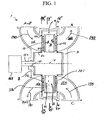
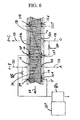
- FIG. 1 shows a rotary adsorption module 1, which includes a number "N" (where N is an integer number equal to or greater than 2) of adsorbers 3 or adsorber channels 3 in adsorber housing body 4.
- Each adsorber has a first end 5 and a second end 6, with a flow path therebetween contacting an adsorbent material over which a gas component B is more readily adsorbed relative to a component A and a component C which are less readily adsorbed.
- the adsorbers are deployed in an axisymmetric array about axis 7 of the adsorber housing body.
- the housing body 4 is in relative rotary motion about axis 7 with first and second functional bodies 8 and 9, being engaged across a first valve face 10 with the first functional body 8 to which a first gas mixture containing components A and B is supplied in a first sector and from which a second gas mixture containing components B and C is withdrawn from a second sector, and across a second valve face 11 with the second functional body 9 from which a first or light product enriched in component A is withdrawn in a first sector and to which a displacement purge stream containing component C is supplied in a second sector.
- the adsorber housing 4 rotates and shall henceforth be referred to as the adsorber rotor 4, while the first and second functional bodies are stationary and together constitute a stator assembly of the module.
- the first functional body shall henceforth be referred to as the first valve stator 8
- the second functional body shall henceforth be referred to as the second valve stator 9.
- the adsorber housing 4 may be stationary, while the first and second functional bodies are rotary distributor valve rotors.
- the flow path through the adsorbers is parallel to axis 7, so that the flow direction is axial, while the first and second valve faces are shown as flat annular discs normal to axis 7.
- the flow direction in the adsorbers may be axial or radial relative to the axis of rotation of the rotor or a combination thereof, and the first and second valve faces may shaped according to any figure of revolution centred on axis 7, such as planar, conical, cylindrical, etc.
- the steps of the process and the functional compartments to be defined will be in the same angular relationship regardless of a radial or axial flow direction in the adsorbers.
- FIGS. 2-4 are cross-sections of module 1 in the planes defined by arrows 12'-13', 14'-15', and 16'-17'. Arrow 20 in each section shows the direction of rotation of the rotor 4.
- FIG. 2 shows section 12'-13' across FIG.1 , which crosses the adsorber rotor.
- the adsorbers 3 are mounted between outer wall 21 and inner wall 22 of adsorber wheel 208.
- Each adsorber in the particular embodiment depicted comprises a rectangular flat pack 3 of adsorbent sheets 23, with spacers 24 between the sheets to define flow channels shown here in the axial direction.
- Separators 25 are provided between the adsorbers to fill void space and prevent leakage between the adsorbers.
- the adsorber packs 3 may be radially tapered to improve the volume packing of adsorbent.
- the adsorbers may comprise multiple layers of adsorbent laminate oriented in a concentric spirally wrapped configuration, or other suitable monolithic structure, or alternatively may compose beaded or other particulate adsorbent arrangements.
- the adsorbers 3 may include a plurality of distinct zones between the first end 5 and the second end 6 of the flow channels, here shown as two zones respectively a first zone 26 adjacent the first end 5 and a second zone 28 adjacent the second end 6.
- Each zone in the adsorber 3 may incorporate a different adsorbent material composition.
- the different adsorbent materials may be provided in layers or mixtures that include varying gradients of adsorbent material concentrations along the gas flow path. The transition from one adsorbent material to another may also be a blended mixture of the two adsorbent materials rather than a distinct transition.
- a further option is to provide a mixture of the different adsorbent materials that may or may not be homogeneous.
- the first zone may contain an adsorbent or desiccant material selected for removing very strongly adsorbed components of the feed gas mixture (component E), such as water or methanol vapor, and some carbon dioxide (component B).
- component E very strongly adsorbed components of the feed gas mixture
- component B carbon dioxide
- the second zone may contain an adsorbent typically selected for bulk separation of carbon dioxide (component B).
- the first zone may contain an adsorbent that preferentially adsorbs CO2 relative to water vapor as described above.
- the second zone may contain an adsorbent (e.g., zeolite, Cu(I)-containing material, or Ag(I)-containing material) that preferentially adsorbs CO relative to water vapor.
- the CO2-selective adsorbent and the CO-selective adsorbent may be included or mixed together in a single zone rather than in two distinct zones.
- the adsorbent sheets comprise a substrate (e.g., glass fibre, metal foil or wire mesh) to which the adsorbent material is attached with a suitable binder, as disclosed in more detail above. Satisfactory adsorbent sheets have been made by coating a slurry of zeolite crystals with binder constituents onto the substrate, with successful examples including nonwoven fibreglass scrims, woven metal (wire mesh) fabrics, and expanded metallic (such as aluminium) foils. Spacing means may be provided by printing or embossing the adsorbent sheet with a raised pattern, or by placing a fabricated spacer between adjacent pairs of adsorbent sheets.
- a substrate e.g., glass fibre, metal foil or wire mesh
- Adsorbers of the layered adsorbent sheet material may be formed by stacking flat or curved sheets, or by forming a spiral roll, with the flow channels between the sheets extending from the first end of the adsorber to the second end thereof, to substantially fill the volume of the adsorber housing of the desired shape. Examples of methods and structures with packed, spirally wound adsorbents are disclosed in commonly owned, co-pending U.S. patent application No. 10/041,536, filed January 7, 2002 .
- Typical experimental sheet thicknesses have varied between about 100-500 microns, with spacer heights in the range of about 75 to 300 microns, and adsorber flow channel lengths in the range of about 10 cm to approximately 60 cm.
- the adsorbers may be provided as an array of spiral rolls of adsorbent sheet and spacers as described above, with the array supported in a rotor.
- the adsorbers may be formed by winding a single spiral roll of adsorbent sheet around the rotor hub and filling the annulus to wall 21.
- Spacers between adjacent adsorbent sheet layers may be formed by longitudinal spacers or corrugations, establishing axial flow channels between the sheets and extending between the first end 5 and second end 6, while the spacers or corrugations prevent flow transverse to the flow channels or between adjacent flow channels. Consequently, each such flow channel is isolated from neighbouring flow channels through the adsorbent mass, and serves as a small independent adsorber. With this approach, the number N of independent adsorbers may be extremely large.
- the adsorbers may be provided as flow channels in a monolith, for example a honeycomb cordierite extrudate with adsorbent material washcoated onto the cell walls of the honeycomb.
- the rotor may be formed from a single extrudate section, or from an array of such sections supported on the rotor.
- the adsorbers and rotor are assembled with co-operating fluid sealing means so that substantially all fluid flow between the first and second ends of the adsorbers passes through the flow channels in the adsorbers, so that bypass leakage is avoided.
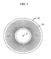
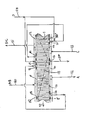
- FIG. 3 shows the porting of rotor 4 in the first and second valve faces respectively in the planes defined by arrows 14'-15', and 16'-17'.
- An adsorber port 30 provides fluid communication directly from the first or second end of each adsorber to respectively the first or second valve face. Each such port 30 may be equivalently provided by a number of small ports for each adsorber.
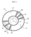
- FIG. 4 shows a typical stator valve face 100 of the first stator 8 in the first valve face 10 and in the plane defined by arrows 14'-15', similar to a valve face 101 of the second stator 9 in the second valve face 11 and in the plane defined by arrows 16'-17'.
- Arrow 20 indicates the direction of rotation by the adsorber rotor.
- the open area of first stator valve face 100 ported to external conduits is indicated by clear angular sectors 111-116, which are separated by radial seals 118 corresponding to the first functional ports communicating directly to functional compartments identified by the same reference numerals 111-116.
- Sector 113 is used for the first buffer step, and sector 114 is used for the second buffer step. If pressure swing is used to augment displacement purge regeneration, a sector 115 may be provided for a pressurization step and a sector 116 may be provided for a depressurization step.
- the open area of second stator valve face 101 (as shown in FIGS. 5 , 7 and 9 ) ported to external conduits is indicated by clear angular sectors 121-126, which are also separated by radial seals 118 corresponding to the first functional ports communicating directly to functional compartments identified by the same reference numerals 111-116.
- Typical radial seal 118 provides a transition for an adsorber between being open to adjacent sectors.
- a gradual opening may be provided by a tapering clearance channel between the slipper and the sealing face, so as to achieve gentle pressure equalization of an adsorber being opened to a new compartment.
- Much wider closed sectors may be provided to substantially stop flow to or from one end of the adsorbers when pressurization or depressurization steps are being performed from the other end.
- feed gas (the first gas mixture including components A and B and potentially E) is supplied to first sector 111 as indicated by arrow 125, while heavy product (the second gas mixture including components B and C) is exhausted from second sector 112 as indicated by arrow 126.
- first or light product gas (enriched in component A) is delivered from first sector 211 as indicated by arrow 127, while displacement purge gas (including component C) is supplied to second sector 122 as indicated by arrow 128.
- the rotor is supported by bearing 160 with shaft seal 161 on rotor drive shaft 162 in the first stator 8, which is integrally assembled with the first and second valve stators.
- the adsorber rotor is driven by motor 163 as exemplary of rotor drive means.
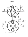
- FIG. 5 shows the first and second stator valve faces 100 and 101 of an embodiment with displacement purge gas as the first buffer purge gas, and the feed or first gas mixture as the second buffer gas.
- the first and second stator valve faces are being viewed in one direction as indicated by section arrows 14'-17'so that the first stator valve face is being viewed from behind while the second valve face is being viewed from in front.
- FIG. 6 shows the flow pattern through the adsorbers, in a circumferential section including the angular range of 0° to 360° about axis 7.
- the dashed line across the adsorbers 3 in FIGS. 6 , 8 and 10 represent concentration fronts between the gas mixtures A and B, B and C and components A and C.
- dashed line 175 indicates movement at the carbon dioxide concentration front during the cycle.
- the first buffer purge gas is admitted by valve 180 to sector 123 in the second valve face 101, and displaces gas from sector 113 in the first valve face to a secondary processing unit, in this case, to burner 182 with co-operating heat recovery means 183.
- the second buffer purge gas is admitted by valve 185 to sector 114 in the first valve face 100, and displaces gas from sector 123 in the second valve face to burner 182 with co-operating heat recovery means 183.
- the heat recovery means may be a heat exchanger to preheat oxidant and fuel streams being supplied to the fuel cell, or a steam generator, or an internal combustion engine, or a gas turbine, or a Stirling engine.
- FIG. 7 shows the first and second stator valve faces 100 and 101 of an embodiment with recycled flue gas as the first and second buffer purge gases, with this flue gas obtained by combustion of the buffer purge gases so that unbound component C is removed from the first buffer purge gas and unbound component A is removed from the second buffer purge gas.
- FIG. 8 shows the flow pattern through the adsorbers, in a circumferential section including the angular range of 0° to 360° about axis 7.
- the buffer gas streams are admitted to the first valve face 100, with the first buffer stream through sector 113 and the second buffer stream through sector 114. A portion of the first buffer stream is recirculated from sector 113' back to sector 113, after being displaced by the initially entering displacement purge stream.
- the first buffer stream is withdrawn from sector 123 by blower or vacuum pump 187, and the second buffer stream is withdrawn from sector 124 by blower or vacuum pump 187'.
- the buffer streams are passed through burner 182 with co-operating heat recovery means 183, and then through condenser 189 to reject excess water through discharge conduit 190.
- Complete or partial separation of the first and second buffer streams may be maintained through burner 182 and condenser 189, as indicated by dashed partitions 191 and 192, so that combustion conditions on each side of partition 191 may be maintained appropriately fuel rich on the first buffer stream side in order to remove unbound component C from the first buffer purge gas, and lean on the second buffer stream side to remove unbound component A from the second buffer purge gas.
- the first and second buffer streams may be mixed through a single blower and/or vacuum pump 187, and through the burner and condenser, by maintaining closely stoichiometric combustion conditions in the burner so that unbound components A and C are both extinguished.
- the burner may be a catalytic combustor in order to achieve satisfactory and sufficiently complete combustion under all conditions.
- FIG. 9 shows the first and second stator valve faces 100 and 101 of an embodiment with combined pressure swing and displacement purge regeneration and with recycled flue gas as the first and second buffer purge gases.
- FIG. 10 shows the flow pattern through the adsorbers, in a circumferential section including the angular range of 0° to 360° about axis 7.
- sector 115 is used for a feed pressurization step, with feed gas mixture introduced through an orifice or pressure reduction restrictor 193, while sector 116 is used for a countercurrent blowdown step for depressurization preceding the first buffer step.
- sector 125 provides a repressurization step by light reflux (pressure equalization) through conduit 195 and restrictor 196 with sector 126 which provides the corresponding depressurization step.
- Sector 125' provides another repressurization step by light reflux (pressure equalization) through conduit 195' and restrictor 196' with sector 126' which provides the corresponding depressurization step.
- Extended closed sectors of valve face 100 are provided as wide radial seals (e.g. 197, 197') opposite the light reflux sectors 125,125', 126 and 126' of face 101.
- wide radial seals e.g. 198, 198'
- the radial seals leading sectors 111, 115, 116, 125, 125', 126, and 126' have tapered clearance gaps (e.g. 199) between the rotor face and the respective seal entering those sectors, so as to provide smooth pressurization and depressurization transitions by flow throttling in the tapered clearance as each adsorber comes into registration with the corresponding sector.
- a purge step using light reflux of enriched component B may be included in addition to a displacement purge step including component C.
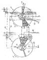
- FIG. 11 shows the first and second stator valve faces 100 and 101 of an embodiment with buffer purge gases.
- the first and second stator valve faces are being viewed in one direction, as indicated in previous figures, so that the first stator valve face is being viewed from behind while the second valve face is being viewed from in front.
- FIG. 12 shows the flow pattern through the adsorbers, in a circumferential section including the angular range of 0° to 360° about axis 7.
- the device separates a feed mixture of A, B, E such that A is enriched and separated from B and E, and B and E are recovered together with purge gas C]
- Buffer gas streams are admitted to the first valve face 100, with the first buffer stream through sector 113 and the second buffer stream through sector 114.
- the first buffer stream is recirculated from sector 126 of the second valve face 101 back to sector 113, after being displaced by the initially entering feed gas mixture stream.
- the first buffer stream displaces enriched component A through sector 121 of second valve face 101 thereby enhancing recovery of light component A.
- the second buffer stream 137 is withdrawn from sector 123 and is sent for appropriate secondary processing for regeneration of buffer gas or exhausted to flue stack. Remaining buffer gas is withdrawn from sector 115 and recycled back to sector 124 of the second valve face 101, after being displaced by the initially entering displacement purge stream.
- Buffer gas streams are admitted to the second valve face 101, with the third buffer stream through sector 124 and the fourth buffer stream through sector 125.
- the third buffer stream is recycled as described above.
- the third and fourth buffer streams continue as displacement purge for component B through sector 112 of first valve face 100 thereby enhancing recovery of heavy component B. Remaining interstitial buffer gas is withdrawn from sector 126 and recycled as described above.
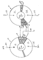
- FIG. 13 shows the first and second stator valve faces 100 and 101 of an embodiment with buffer purge gases.
- the first and second stator valve faces are being viewed in one direction, as indicated in previous figures, so that the first stator valve face is being viewed from behind while the second valve face is being viewed from in front.
- FIG. 14 shows the flow pattern through dual coaxial annularly-configured adsorber sets, in a circumferential section including the angular range of 0° to 360° about axis 7.
- a feed stream containing gas components A, B, and E is to be separated such that components A and E are recovered together, and component B is recovered with purge gas C.
- Annular adsorber 1 contains adsorbent as in previous examples to which component B is more strongly adsorbed than both components A and E (ex. activated carbon in the case of carbon dioxide as component B, hydrogen as component A and water vapour as component E).
- Annular adsorber 2 contains adsorbent to which component E is more strongly adsorbed than both components A and B (ex. activated alumina in the same exemplary case described above).
- Feed gas stream 130 containing components A, B, and E is admitted to the second valve face 101 1 through 127 of annular adsorber 2.
- the gas exits through 116 of the first valve face 100 and then is directed back into annular adsorber 1 sector 111 of first valve face 100.
- Stream 134 exits via 121 of second valve face 101 as a stream of enriched A and is directed to annular adsorber 2 sector 117 of first valve face 100.
- Product stream 132 exits the system as enriched product A with recovered component E from 128 of second valve face 101.
- a control system can be employed in the operation of this machine which allows one to vary the amount of E that is recovered with enriched A.
- a portion of stream 130 can be diverted through stream 135 to sector 111 of annular adsorber 1 of first valve face 100 using flow regulating device 136.
- the portion of component E transferred through stream 135 will be recovered in stream 131 with components B and C.
- the remaining portion of stream 130 is admitted to section 127 and the E component of the portion is recovered with the enriched component A as described above.
Landscapes
- Chemical & Material Sciences (AREA)
- Engineering & Computer Science (AREA)
- Analytical Chemistry (AREA)
- General Chemical & Material Sciences (AREA)
- Oil, Petroleum & Natural Gas (AREA)
- Chemical Kinetics & Catalysis (AREA)
- Separation Of Gases By Adsorption (AREA)
- Auxiliary Devices For And Details Of Packaging Control (AREA)
- Hydrogen, Water And Hydrids (AREA)
Applications Claiming Priority (3)
| Application Number | Priority Date | Filing Date | Title |
|---|---|---|---|
| US36477202P | 2002-03-14 | 2002-03-14 | |
| US364772P | 2002-03-14 | ||
| PCT/CA2003/000372 WO2003076048A1 (en) | 2002-03-14 | 2003-03-14 | Gas separation by combined pressure swing and displacement purge |
Publications (2)
| Publication Number | Publication Date |
|---|---|
| EP1483035A1 EP1483035A1 (en) | 2004-12-08 |
| EP1483035B1 true EP1483035B1 (en) | 2011-09-14 |
Family
ID=27805307
Family Applications (1)
| Application Number | Title | Priority Date | Filing Date |
|---|---|---|---|
| EP03743781A Expired - Lifetime EP1483035B1 (en) | 2002-03-14 | 2003-03-14 | Gas separation by combined pressure swing and displacement purge |
Country Status (8)
| Country | Link |
|---|---|
| US (1) | US6902602B2 (enExample) |
| EP (1) | EP1483035B1 (enExample) |
| JP (1) | JP2005519731A (enExample) |
| CN (1) | CN100493670C (enExample) |
| AT (1) | ATE524228T1 (enExample) |
| AU (1) | AU2003209894A1 (enExample) |
| CA (1) | CA2477262A1 (enExample) |
| WO (1) | WO2003076048A1 (enExample) |
Families Citing this family (122)
| Publication number | Priority date | Publication date | Assignee | Title |
|---|---|---|---|---|
| EP1344270B1 (en) * | 2000-10-27 | 2017-06-21 | Air Products and Chemicals, Inc. | Systems and processes for providing hydrogen to fuel cells |
| AU2002246964A1 (en) * | 2001-01-05 | 2002-09-04 | Questair Technologies, Inc. | Adsorbent coating compositions, laminates and adsorber elements comprising such compositions and methods for their manufacture and use |
| US7838708B2 (en) | 2001-06-20 | 2010-11-23 | Grt, Inc. | Hydrocarbon conversion process improvements |
| CA2476409A1 (en) | 2002-03-14 | 2003-09-18 | Questair Technologies Inc. | Hydrogen recycle for solid oxide fuel cell |
| US7285350B2 (en) * | 2002-09-27 | 2007-10-23 | Questair Technologies Inc. | Enhanced solid oxide fuel cell systems |
| WO2004067684A2 (en) * | 2003-01-30 | 2004-08-12 | Questair Technologies, Inc. | Compact synthesis gas generation system |
| EP1652255A2 (en) * | 2003-02-26 | 2006-05-03 | QuestAir Technologies Inc. | Hydrogen recycle for high temperature fuel cells |
| EP1682465A1 (en) | 2003-07-15 | 2006-07-26 | GRT, Inc. | Hydrocarbon synthesis |
| US20050171393A1 (en) | 2003-07-15 | 2005-08-04 | Lorkovic Ivan M. | Hydrocarbon synthesis |
| US8173851B2 (en) | 2004-04-16 | 2012-05-08 | Marathon Gtf Technology, Ltd. | Processes for converting gaseous alkanes to liquid hydrocarbons |
| US20080275284A1 (en) | 2004-04-16 | 2008-11-06 | Marathon Oil Company | Process for converting gaseous alkanes to liquid hydrocarbons |
| US20060100469A1 (en) | 2004-04-16 | 2006-05-11 | Waycuilis John J | Process for converting gaseous alkanes to olefins and liquid hydrocarbons |
| US8642822B2 (en) | 2004-04-16 | 2014-02-04 | Marathon Gtf Technology, Ltd. | Processes for converting gaseous alkanes to liquid hydrocarbons using microchannel reactor |
| US7244867B2 (en) | 2004-04-16 | 2007-07-17 | Marathon Oil Company | Process for converting gaseous alkanes to liquid hydrocarbons |
| US7674941B2 (en) | 2004-04-16 | 2010-03-09 | Marathon Gtf Technology, Ltd. | Processes for converting gaseous alkanes to liquid hydrocarbons |
| US7101414B2 (en) * | 2004-04-27 | 2006-09-05 | Munters Corporation | Rotary bed sorption system including at least one recycled isolation loop, and methods of designing and operating such a system |
| US20050249645A1 (en) * | 2004-05-05 | 2005-11-10 | Eaton Corporation | Catalyst and adsorbant bed configurations suitable for mobile applications |
| US7189280B2 (en) * | 2004-06-29 | 2007-03-13 | Questair Technologies Inc. | Adsorptive separation of gas streams |
| US20060048648A1 (en) * | 2004-08-20 | 2006-03-09 | Questair Technologies Inc. | Parallel passage contactor structure |
| US20060090646A1 (en) * | 2004-11-04 | 2006-05-04 | Questair Technologies Inc. | Adsorbent material for selective adsorption of carbon monoxide and unsaturated hydrocarbons |
| WO2006052937A2 (en) * | 2004-11-05 | 2006-05-18 | Questair Technologies, Inc. | Separation of carbon dioxide from other gases |
| US7833311B2 (en) * | 2004-12-20 | 2010-11-16 | Idatech, Llc | Temperature-based breakthrough detection and pressure swing adsorption systems and fuel processing systems including the same |
| US7393382B2 (en) * | 2004-12-20 | 2008-07-01 | Idatech Llc | Temperature-based breakthrough detection and pressure swing adsorption systems and fuel processing systems including the same |
| US7399342B2 (en) * | 2004-12-22 | 2008-07-15 | Idatech, Llc | Systems and methods for regulating heating assembly operation through pressure swing adsorption purge control |
| CN101124042A (zh) * | 2005-01-03 | 2008-02-13 | 探索空气技术公司 | 用于制造平行通道接触器的方法 |
| JP2008526494A (ja) * | 2005-01-07 | 2008-07-24 | クエストエアー テクノロジーズ インコーポレイテッド | 速度分離のための工学的吸着構造 |
| CA2607205A1 (en) * | 2005-06-15 | 2006-12-21 | Questair Technologies Inc. | Adsorptive bulk separation for upgrading gas streams |
| JP5240889B2 (ja) | 2005-07-13 | 2013-07-17 | 月島機械株式会社 | 揮発性有機化合物の濃縮装置及び濃縮方法、並びに揮発性有機化合物の回収設備及び回収方法 |
| US7763098B2 (en) * | 2005-11-18 | 2010-07-27 | Xebec Adsorption Inc. | Rapid cycle syngas pressure swing adsorption system |
| FR2895272B1 (fr) * | 2005-12-22 | 2008-06-06 | Inst Francais Du Petrole | Procede et dispositif de production en continu d'un gaz riche en oxygene a partir d'un gaz d'alimentation contenant de l'oxygene |
| WO2007092410A2 (en) | 2006-02-03 | 2007-08-16 | Grt, Inc. | Separation of light gases from halogens |
| KR101368416B1 (ko) | 2006-02-03 | 2014-03-05 | 리액션 35, 엘엘씨 | 천연 가스를 액체 탄화수소로 변환시키는 연속 공정 |
| US8444750B2 (en) * | 2007-05-18 | 2013-05-21 | Exxonmobil Research And Engineering Company | Removal of CO2, N2, or H2S from gas mixtures by swing adsorption with low mesoporosity adsorbent contactors |
| CA2688638C (en) * | 2007-05-18 | 2016-06-21 | Exxonmobil Research And Engineering Company | Removal of a target gas from a mixture of gases by swing adsorption with use of a turboexpander |
| US7959720B2 (en) * | 2007-05-18 | 2011-06-14 | Exxonmobil Research And Engineering Company | Low mesopore adsorbent contactors for use in swing adsorption processes |
| US8529663B2 (en) * | 2007-05-18 | 2013-09-10 | Exxonmobil Research And Engineering Company | Process for removing a target gas from a mixture of gases by swing adsorption |
| US8545602B2 (en) * | 2007-05-18 | 2013-10-01 | Exxonmobil Research And Engineering Company | Removal of CO2, N2, and H2S from gas mixtures containing same |
| CN101765574A (zh) | 2007-05-24 | 2010-06-30 | Grt公司 | 使卤化氢可逆性俘获与释放相结合的区域反应器 |
| US8070841B2 (en) * | 2007-12-12 | 2011-12-06 | Idatech, Llc | Systems and methods for supplying auxiliary fuel streams during intermittent byproduct discharge from pressure swing adsorption assemblies |
| US7837765B2 (en) | 2007-12-12 | 2010-11-23 | Idatech, Llc | Systems and methods for supplying auxiliary fuel streams during intermittent byproduct discharge from pressure swing adsorption assemblies |
| US8309259B2 (en) | 2008-05-19 | 2012-11-13 | Arizona Board Of Regents For And On Behalf Of Arizona State University | Electrochemical cell, and particularly a cell with electrodeposited fuel |
| US8282810B2 (en) * | 2008-06-13 | 2012-10-09 | Marathon Gtf Technology, Ltd. | Bromine-based method and system for converting gaseous alkanes to liquid hydrocarbons using electrolysis for bromine recovery |
| US9752022B2 (en) | 2008-07-10 | 2017-09-05 | Avery Dennison Corporation | Composition, film and related methods |
| KR101740419B1 (ko) | 2008-07-18 | 2017-05-26 | 지알티, 인코포레이티드 | 천연 가스를 액체 탄화수소로 변환시키는 연속 공정 |
| US8491763B2 (en) * | 2008-08-28 | 2013-07-23 | Fluidic, Inc. | Oxygen recovery system and method for recovering oxygen in an electrochemical cell |
| TWI342946B (en) * | 2008-11-07 | 2011-06-01 | Univ Nat Chiao Tung | Tube bundle heater exchanger of constant temperature gradient for thermophoretic deposition of aerosol particles |
| WO2011044528A1 (en) | 2009-10-08 | 2011-04-14 | Fluidic, Inc. | Rechargeable metal-air cell with flow management system |
| WO2011106718A1 (en) * | 2010-02-25 | 2011-09-01 | Georgia Tech Research Corporation | Adsorbing heat exchangers |
| US8198495B2 (en) | 2010-03-02 | 2012-06-12 | Marathon Gtf Technology, Ltd. | Processes and systems for the staged synthesis of alkyl bromides |
| US8367884B2 (en) | 2010-03-02 | 2013-02-05 | Marathon Gtf Technology, Ltd. | Processes and systems for the staged synthesis of alkyl bromides |
| RU2571140C2 (ru) | 2010-03-04 | 2015-12-20 | Авери Деннисон Корпорейшн | Не содержащая пвх пленка и не содержащая пвх многослойная пленка |
| JP5788502B2 (ja) | 2010-06-24 | 2015-09-30 | フルイディック, インク.Fluidic, Inc. | 階段状スキャフォールド燃料アノードを備える電気化学セル |
| CN202550031U (zh) | 2010-09-16 | 2012-11-21 | 流体公司 | 具有渐进析氧电极/燃料电极的电化学电池系统 |
| CN102456934B (zh) | 2010-10-20 | 2016-01-20 | 流体公司 | 针对基架燃料电极的电池重置过程 |
| JP5908251B2 (ja) | 2010-11-17 | 2016-04-26 | フルイディック,インク.Fluidic,Inc. | 階層型アノードのマルチモード充電 |
| US8715394B2 (en) * | 2010-11-24 | 2014-05-06 | Lehigh University | Autothermal cycle for CO2 capture |
| CA2842928A1 (en) | 2011-03-01 | 2012-11-29 | Exxonmobil Upstream Research Company | Apparatus and systems having a rotary valve assembly and swing adsorption processes related thereto |
| MX336393B (es) | 2011-03-01 | 2016-01-18 | Exxonmobil Upstream Res Co | Aparatos y sistemas que tienen un contactor adsorbente encerrado y procesos de adsorcion oscilante relacionados con los mismos. |
| US8815050B2 (en) | 2011-03-22 | 2014-08-26 | Marathon Gtf Technology, Ltd. | Processes and systems for drying liquid bromine |
| FR2975017B1 (fr) * | 2011-05-09 | 2015-11-13 | Air Liquide | Unite de purification par adsorption avec distributeur rotatif et moyen de reglage des debits |
| US8436220B2 (en) | 2011-06-10 | 2013-05-07 | Marathon Gtf Technology, Ltd. | Processes and systems for demethanization of brominated hydrocarbons |
| US8829256B2 (en) | 2011-06-30 | 2014-09-09 | Gtc Technology Us, Llc | Processes and systems for fractionation of brominated hydrocarbons in the conversion of natural gas to liquid hydrocarbons |
| US8802908B2 (en) | 2011-10-21 | 2014-08-12 | Marathon Gtf Technology, Ltd. | Processes and systems for separate, parallel methane and higher alkanes' bromination |
| US9193641B2 (en) | 2011-12-16 | 2015-11-24 | Gtc Technology Us, Llc | Processes and systems for conversion of alkyl bromides to higher molecular weight hydrocarbons in circulating catalyst reactor-regenerator systems |
| TWI630021B (zh) | 2012-06-14 | 2018-07-21 | 艾克頌美孚研究工程公司 | 用於co捕捉/利用和n製造之變壓吸附與發電廠的整合 |
| CN102755810A (zh) * | 2012-08-02 | 2012-10-31 | 南京圣火水泥新技术工程有限公司 | 转子式变压吸附气体分离装置 |
| CN105899587A (zh) | 2013-12-30 | 2016-08-24 | 艾利丹尼森公司 | 聚氨酯保护性膜 |
| CA2949262C (en) | 2014-07-25 | 2020-02-18 | Shwetha Ramkumar | Cyclical swing absorption process and system |
| EP3218326B1 (en) | 2014-11-11 | 2020-03-04 | ExxonMobil Upstream Research Company | High capacity structures and monoliths via paste imprinting |
| EP3229938A1 (en) | 2014-12-10 | 2017-10-18 | ExxonMobil Research and Engineering Company | Adsorbent-incorporated polymer fibers in packed bed and fabric contactors, and methods and devices using same |
| SG10201912671YA (en) | 2014-12-23 | 2020-03-30 | Exxonmobil Upstream Res Co | Structured adsorbent beds, methods of producing the same and uses thereof |
| WO2016186725A1 (en) | 2015-05-15 | 2016-11-24 | Exxonmobil Upstream Research Company | Apparatus and system for swing adsorption processes related thereto comprising mid-bed purge systems |
| WO2016186726A1 (en) | 2015-05-15 | 2016-11-24 | Exxonmobil Upstream Research Company | Apparatus and system for swing adsorption processes related thereto |
| WO2017001690A1 (en) * | 2015-07-02 | 2017-01-05 | Solvay Sa | Process for producing sodium carbonate/bicarbonate |
| US10293298B2 (en) | 2015-09-02 | 2019-05-21 | Exxonmobil Upstream Research Company | Apparatus and system for combined temperature and pressure swing adsorption processes related thereto |
| EA201890610A1 (ru) | 2015-09-02 | 2018-07-31 | Эксонмобил Апстрим Рисерч Компани | Способ и система для осуществления короткоцикловой адсорбции с использованием головного потока метаноотгонной колонны в качестве продувочного газа |
| EP3368189A1 (en) | 2015-10-27 | 2018-09-05 | Exxonmobil Upstream Research Company | Apparatus and system for swing adsorption processes related thereto having a plurality of valves |
| AU2016344415B2 (en) | 2015-10-27 | 2019-08-22 | Exxonmobil Upstream Research Company | Apparatus and system for swing adsorption processes related thereto having a plurality of valves |
| JP6615373B2 (ja) | 2015-10-27 | 2019-12-04 | エクソンモービル アップストリーム リサーチ カンパニー | 能動制御型供給ポペット弁及び受動制御型生成物弁を有するスイング吸着プロセス用の装置及びシステム |
| WO2017087385A1 (en) | 2015-11-16 | 2017-05-26 | Exxonmobil Upstream Research Company | Adsorbent materials and methods of adsorbing carbon dioxide |
| WO2017087165A1 (en) | 2015-11-17 | 2017-05-26 | Exxonmobil Research And Engineering Company | Hybrid high-temperature swing adsorption and fuel cell |
| WO2017087164A1 (en) | 2015-11-17 | 2017-05-26 | Exxonmobil Research And Engineering Company | Integration of staged complementary psa system with a power plant for co2 capture/utilization and n2 production |
| WO2017087166A1 (en) | 2015-11-17 | 2017-05-26 | Exxonmobil Research And Engineering Company | Dual integrated psa for simultaneous power plant emission control and enhanced hydrocarbon recovery |
| WO2017087167A1 (en) | 2015-11-17 | 2017-05-26 | Exxonmobil Research And Engineering Company | Staged complementary psa system for low energy fractionation of mixed fluid |
| WO2017087154A1 (en) | 2015-11-17 | 2017-05-26 | Exxonmobil Research And Engineering Company | Staged pressure swing adsorption for simultaneous power plant emission control and enhanced hydrocarbon recovery |
| KR102194968B1 (ko) | 2016-03-18 | 2020-12-28 | 엑손모빌 업스트림 리서치 캄파니 | 관련 스윙 흡착 공정을 위한 장치 및 시스템 |
| WO2017165976A1 (en) * | 2016-03-31 | 2017-10-05 | Inventys Thermal Technologies Inc. | Adsorptive gas separator with reduced thermal conductivity |
| US10427089B2 (en) | 2016-05-31 | 2019-10-01 | Exxonmobil Upstream Research Company | Apparatus and system for swing adsorption processes |
| CA3025699A1 (en) | 2016-05-31 | 2017-12-07 | Exxonmobil Upstream Research Company | Apparatus and system for swing adsorption processes |
| US11144075B2 (en) | 2016-06-30 | 2021-10-12 | Ichor Systems, Inc. | Flow control system, method, and apparatus |
| CA3019358A1 (en) | 2016-07-22 | 2018-01-25 | Nantenergy, Inc. | Mist elimination system for electrochemical cells |
| JP2019521497A (ja) | 2016-07-22 | 2019-07-25 | ナントエナジー,インク. | 電気化学セル内の水分及び二酸化炭素管理システム |
| WO2018026518A1 (en) | 2016-08-04 | 2018-02-08 | Exxonmobil Research And Engineering Company | High temperature pressure swing adsorption for advanced sorption enhanced water gas shift |
| WO2018026516A1 (en) | 2016-08-04 | 2018-02-08 | Exxonmobil Research And Engineering Company | High purity nitrogen/hydrogen production from an exhaust stream |
| US10434458B2 (en) | 2016-08-31 | 2019-10-08 | Exxonmobil Upstream Research Company | Apparatus and system for swing adsorption processes related thereto |
| SG11201900842QA (en) | 2016-09-01 | 2019-03-28 | Exxonmobil Upstream Res Co | Swing adsorption processes for removing water using 3a zeolite structures |
| BR112019004880A2 (pt) | 2016-09-15 | 2019-06-11 | Nantenergy, Inc. | sistema de bateria híbrida |
| US10328382B2 (en) | 2016-09-29 | 2019-06-25 | Exxonmobil Upstream Research Company | Apparatus and system for testing swing adsorption processes |
| WO2018075870A1 (en) | 2016-10-21 | 2018-04-26 | Fluidic Inc. | Corrugated fuel electrode |
| AU2017379685B2 (en) | 2016-12-21 | 2020-03-12 | Exxonmobil Upstream Research Company | Self-supporting structures having foam-geometry structure and active materials |
| RU2720940C1 (ru) | 2016-12-21 | 2020-05-14 | Эксонмобил Апстрим Рисерч Компани | Самоподдерживающиеся структуры, имеющие активные материалы |
| US20180250654A1 (en) * | 2017-03-03 | 2018-09-06 | Exxonmobil Research And Engineering Company | Calcination of co2/h2o displacement desorption sorbents |
| US11420182B2 (en) | 2017-03-03 | 2022-08-23 | ExxonMobile Technology and Engineering Company | Hydrophobic sorbents for CO2/H2O displacement desorption applications |
| WO2019147516A1 (en) | 2018-01-24 | 2019-08-01 | Exxonmobil Upstream Research Company | Apparatus and system for temperature swing adsorption |
| EP3758828A1 (en) | 2018-02-28 | 2021-01-06 | ExxonMobil Upstream Research Company | Apparatus and system for swing adsorption processes |
| CN112805868A (zh) | 2018-06-29 | 2021-05-14 | 福恩能源公司 | 金属空气电化学电池构架 |
| US12237548B2 (en) | 2018-06-29 | 2025-02-25 | Form Energy, Inc. | Stack of electric batteries including series of fluidly connected unit cells |
| WO2020051563A1 (en) * | 2018-09-07 | 2020-03-12 | Matuszak Daniel | Molecular transfer systems and methods for the removal and reactive disguisement of gas constituents |
| US11318410B2 (en) | 2018-12-21 | 2022-05-03 | Exxonmobil Upstream Research Company | Flow modulation systems, apparatus, and methods for cyclical swing adsorption |
| US11782033B2 (en) * | 2019-01-18 | 2023-10-10 | The Regents Of The University Of Michigan | Microscale collector-injector technologies for passive environmental vapor sampling and focused injection |
| WO2020222932A1 (en) | 2019-04-30 | 2020-11-05 | Exxonmobil Upstream Research Company | Rapid cycle adsorbent bed |
| EP3966887B1 (en) | 2019-05-10 | 2025-07-02 | Form Energy, Inc. | Nested annular metal-air cell and systems containing same |
| US12308414B2 (en) | 2019-06-28 | 2025-05-20 | Form Energy, Inc. | Device architectures for metal-air batteries |
| JP7413505B2 (ja) | 2019-08-05 | 2024-01-15 | アイコール・システムズ・インク | 層流制限器 |
| US11841036B2 (en) | 2019-08-05 | 2023-12-12 | Ichor Systems, Inc. | Laminar flow restrictor and seal for same |
| JP7530961B2 (ja) * | 2019-08-05 | 2024-08-08 | アイコール・システムズ・インク | 流量制限器用のシール |
| US11655910B2 (en) | 2019-10-07 | 2023-05-23 | ExxonMobil Technology and Engineering Company | Adsorption processes and systems utilizing step lift control of hydraulically actuated poppet valves |
| US11433346B2 (en) | 2019-10-16 | 2022-09-06 | Exxonmobil Upstream Research Company | Dehydration processes utilizing cationic zeolite RHO |
| US12381244B2 (en) | 2020-05-06 | 2025-08-05 | Form Energy, Inc. | Decoupled electrode electrochemical energy storage system |
| US11731075B2 (en) | 2020-08-10 | 2023-08-22 | Praxair Technology, Inc. | High recovery process for purification of multicomponent gases |
| CA3212503A1 (en) * | 2021-03-04 | 2022-09-09 | Echeneidae Inc. | System and method for mobile carbon capture |
| WO2025009440A1 (ja) * | 2023-07-04 | 2025-01-09 | 住友精化株式会社 | 回収方法及び回収装置 |
Citations (4)
| Publication number | Priority date | Publication date | Assignee | Title |
|---|---|---|---|---|
| US4077779A (en) * | 1976-10-15 | 1978-03-07 | Air Products And Chemicals, Inc. | Hydrogen purification by selective adsorption |
| EP0219103A2 (en) * | 1985-10-18 | 1987-04-22 | Air Products And Chemicals, Inc. | Oxidation of carbonaceous material |
| EP0411506A2 (en) * | 1989-08-02 | 1991-02-06 | Air Products And Chemicals, Inc. | Production of hydrogen, carbon monoxide and mixtures thereof |
| WO2000076628A1 (en) * | 1999-06-09 | 2000-12-21 | Questair Technologies Inc. | Rotary pressure swing adsorption apparatus |
Family Cites Families (175)
| Publication number | Priority date | Publication date | Assignee | Title |
|---|---|---|---|---|
| US607854A (en) * | 1898-07-26 | Charles francis huntoon | ||
| US3094569A (en) * | 1958-10-20 | 1963-06-18 | Union Carbide Corp | Adsorptive separation process |
| US3204388A (en) * | 1960-02-01 | 1965-09-07 | Atlantic Res Corp | Buffer bed dehumidification |
| NL266305A (enExample) * | 1960-09-16 | 1900-01-01 | ||
| BE677537A (enExample) * | 1965-03-12 | 1966-08-01 | ||
| US3430418A (en) * | 1967-08-09 | 1969-03-04 | Union Carbide Corp | Selective adsorption process |
| GB1298818A (en) * | 1968-12-20 | 1972-12-06 | Kobe Steel Ltd | Separation of oxygen from air |
| US3564816A (en) * | 1968-12-30 | 1971-02-23 | Union Carbide Corp | Selective adsorption process |
| US3847672A (en) | 1971-08-18 | 1974-11-12 | United Aircraft Corp | Fuel cell with gas separator |
| US3865924A (en) * | 1972-03-03 | 1975-02-11 | Inst Gas Technology | Process for regenerative sorption of CO{HD 2 |
| US4019879A (en) * | 1975-09-26 | 1977-04-26 | Union Carbide Corporation | Selective adsorption of carbon monoxide from gas streams |
| GB1559325A (en) * | 1976-02-27 | 1980-01-16 | Boc Ltd | Gas separation |
| US4153434A (en) * | 1976-04-07 | 1979-05-08 | General Cable Corporation | Emergency standby air drying back-up system |
| US4322394A (en) * | 1977-10-31 | 1982-03-30 | Battelle Memorial Institute | Adsorbent regeneration and gas separation utilizing microwave heating |
| JPS54138869A (en) * | 1978-04-21 | 1979-10-27 | Mitsubishi Heavy Ind Ltd | Gas separating and refining apparatus |
| GB2042365B (en) | 1979-03-05 | 1983-02-16 | Boc Ltd | Gas separation |
| US4200682A (en) * | 1979-03-16 | 1980-04-29 | United Technologies Corporation | Integrated fuel cell and fuel conversion apparatus |
| US4272265A (en) * | 1979-06-22 | 1981-06-09 | Essex Cryogenics Of Missouri, Inc. | Apparatus for pressure swing generation of oxygen |
| US4233038A (en) * | 1979-08-06 | 1980-11-11 | Air Products And Chemicals, Inc. | Reactivation system for water-carbon dioxide adsorbers |
| US4431432A (en) * | 1980-12-26 | 1984-02-14 | Mitsubishi Jukogyo Kabushiki Kaisha | Process and apparatus for separating a mixed gas such as air |
| US4354859A (en) | 1981-08-06 | 1982-10-19 | Union Carbide Corporation | Enhanced gas separation by selective adsorption |
| US4470829A (en) | 1981-08-31 | 1984-09-11 | Nippon Steel Corporation | Solid adsorbent for carbon monoxide and process for separation from gas mixture |
| US4555453A (en) | 1981-10-01 | 1985-11-26 | Electric Power Research, Inc. | Method for forming molten carbonate fuel cell component and structure |
| US4406675A (en) * | 1981-12-10 | 1983-09-27 | Union Carbide Corporation | RPSA Process |
| CA1226270A (en) * | 1982-03-13 | 1987-09-01 | Hidefumi Hirai | Carbon monoxide adsorbent/separating agent and method of producing same |
| US4452612A (en) * | 1982-09-22 | 1984-06-05 | Cubemco, Inc. | Separation and purification of gases and vapors by continuous pressure-swing adsorption |
| JPS5975574A (ja) | 1982-10-23 | 1984-04-28 | Jgc Corp | 水素発電システム |
| US4801308A (en) * | 1983-10-03 | 1989-01-31 | Keefer Bowie | Apparatus and process for pressure swing adsorption separation |
| US4816121A (en) * | 1983-10-03 | 1989-03-28 | Keefer Bowie | Gas phase chemical reactor |
| US4702903A (en) | 1983-10-03 | 1987-10-27 | Keefer Bowie | Method and apparatus for gas separation and synthesis |
| EP0143537B1 (en) | 1983-10-03 | 1990-03-21 | Bowie Gordon Keefer | Method and apparatus for gas separation and synthesis |
| US4726816A (en) * | 1983-11-08 | 1988-02-23 | Union Carbide Corporation | Reformer-pressure swing adsorption process for the production of carbon monoxide |
| US4578214A (en) * | 1984-02-06 | 1986-03-25 | C F Braun & Co. | Process for ammonia syngas manufacture |
| US4553981A (en) | 1984-02-07 | 1985-11-19 | Union Carbide Corporation | Enhanced hydrogen recovery from effluent gas streams |
| US4530705A (en) * | 1984-04-16 | 1985-07-23 | Firey Joseph C | Cyclic gas separator |
| JPS60186181U (ja) | 1984-05-21 | 1985-12-10 | 株式会社 カモシカスポ−ツ | ピツケル、バイル等のヘツド |
| DE3567579D1 (en) * | 1984-07-04 | 1989-02-23 | Nippon Kokan Kk | Method of separating carbon monoxide |
| JPS6171561A (ja) * | 1984-09-14 | 1986-04-12 | Mitsubishi Heavy Ind Ltd | 燃料電池複合プラント |
| US4532192A (en) * | 1984-11-06 | 1985-07-30 | Energy Research Corporation | Fuel cell system |
| US4783433A (en) | 1985-11-19 | 1988-11-08 | Nippon Kokan Kabushiki Kaisha | Selective adsorbent for CO and method of manufacturing the same |
| JPH06103631B2 (ja) * | 1986-01-23 | 1994-12-14 | 株式会社日立製作所 | 燃料電池システムの空気供給系装置 |
| JPS62274561A (ja) | 1986-05-22 | 1987-11-28 | Mitsubishi Heavy Ind Ltd | 溶融炭酸塩型燃料電池 |
| JPS62278770A (ja) | 1986-05-27 | 1987-12-03 | Nippon Kokan Kk <Nkk> | 転炉ガスからのco↓2,h↓2回収方法 |
| ATE95720T1 (de) * | 1986-06-12 | 1993-10-15 | Ici Plc | Adsorptionsprozess. |
| JPS6328422A (ja) * | 1986-07-21 | 1988-02-06 | Nippon Kokan Kk <Nkk> | ガス吸着、分離装置 |
| JPS63166702A (ja) | 1986-12-26 | 1988-07-09 | Osaka Oxygen Ind Ltd | 酸素ガス濃縮法 |
| JPH0451751Y2 (enExample) | 1987-04-17 | 1992-12-04 | ||
| US4968329A (en) | 1987-10-26 | 1990-11-06 | Keefer Bowie | Pressure swing adsorption for concentration of a gas component |
| US4917711A (en) * | 1987-12-01 | 1990-04-17 | Peking University | Adsorbents for use in the separation of carbon monoxide and/or unsaturated hydrocarbons from mixed gases |
| JPH01155945A (ja) * | 1987-12-12 | 1989-06-19 | Kansai Coke & Chem Co Ltd | Co分離回収用吸着剤の製造法 |
| US4790858A (en) | 1988-01-29 | 1988-12-13 | Air Products And Chemicals, Inc. | Fractionation of multicomponent gas mixtures by pressure swing adsorption |
| US4963339A (en) | 1988-05-04 | 1990-10-16 | The Boc Group, Inc. | Hydrogen and carbon dioxide coproduction |
| US4859545A (en) | 1988-05-05 | 1989-08-22 | International Fuel Cells Corporation | Cathode flow control for fuel cell power plant |
| NL8801492A (nl) | 1988-06-10 | 1990-01-02 | Kinetics Technology | Werkwijze voor het omzetten van brandstof in electriciteit. |
| JPH0794200B2 (ja) | 1988-07-04 | 1995-10-11 | トリニテイ工業株式会社 | 塗膜剥離装置 |
| FR2633847B1 (fr) | 1988-07-08 | 1991-04-19 | Air Liquide | Procede de traitement d'un melange gazeux par adsorption |
| JPH02117072A (ja) * | 1988-10-26 | 1990-05-01 | Toyo Eng Corp | 燃料電池発電システム |
| JPH02172159A (ja) | 1988-12-24 | 1990-07-03 | Ishikawajima Harima Heavy Ind Co Ltd | 溶融炭酸塩型燃料電池発電方法及び装置 |
| DE3913581A1 (de) | 1989-04-25 | 1990-10-31 | Linde Ag | Verfahren zum betrieb von brennstoffzellen |
| DE3932217A1 (de) | 1989-04-25 | 1990-10-31 | Linde Ag | Verfahren fuer den betrieb von hochtemperatur-brennstoffzellen |
| JP2926259B2 (ja) | 1989-06-09 | 1999-07-28 | 大阪瓦斯株式会社 | 固体電解質燃料電池 |
| CA2016045C (en) | 1990-05-04 | 1994-08-16 | Quest Air Gases Inc. | Gas separation by pressure swing adsorption |
| US5096469A (en) | 1990-07-23 | 1992-03-17 | Keefer Bowie | Adsorptive gas separator with inertial energy exchange |
| US5082473A (en) | 1990-07-23 | 1992-01-21 | Keefer Bowie | Extraction and concentration of a gas component |
| US5258571A (en) | 1990-08-23 | 1993-11-02 | Air Products And Chemicals, Inc. | Separations using highly dispersed cuprous compositions |
| US5126310A (en) * | 1990-08-23 | 1992-06-30 | Air Products And Chemicals, Inc. | Highly dispersed cuprous compositions |
| FR2667801B1 (fr) * | 1990-10-11 | 1992-12-04 | Air Liquide | Procede et equipement de separation par adsorption d'au moins un constituant d'un melange gazeux. |
| US5096470A (en) * | 1990-12-05 | 1992-03-17 | The Boc Group, Inc. | Hydrogen and carbon monoxide production by hydrocarbon steam reforming and pressure swing adsorption purification |
| US5366818A (en) | 1991-01-15 | 1994-11-22 | Ballard Power Systems Inc. | Solid polymer fuel cell systems incorporating water removal at the anode |
| FR2672818B1 (fr) | 1991-02-20 | 1993-04-23 | Air Liquide | Procede de production d'oxygene par adsorption. |
| DE69213309T2 (de) | 1991-05-09 | 1997-01-23 | Mitsubishi Heavy Ind Ltd | Vorrichtung zur Trennung und Zurückgewinnung von Gasen |
| US5271916A (en) | 1991-07-08 | 1993-12-21 | General Motors Corporation | Device for staged carbon monoxide oxidation |
| EP0525521A1 (en) | 1991-08-01 | 1993-02-03 | Mitsubishi Jukogyo Kabushiki Kaisha | Gas separator system |
| JPH0779946B2 (ja) * | 1991-09-13 | 1995-08-30 | 工業技術院長 | ガス吸着・脱離制御方法 |
| FR2684023B1 (fr) * | 1991-11-26 | 1994-01-14 | Air Liquide | Procede de production d'un gaz a teneur substantielle en oxygene. |
| JP2777299B2 (ja) | 1991-12-16 | 1998-07-16 | 三菱電機株式会社 | 燃料電池積層体の水素−水回収機構 |
| US5227598A (en) * | 1991-12-23 | 1993-07-13 | General Electric Company | In place regeneration of adsorbents using microwaves |
| FR2689785B1 (fr) * | 1992-04-13 | 1994-05-20 | Air Liquide | Dispositif rotatif de separation par adsorption d'au moins un constituant d'un melange gazeux. |
| US5256172A (en) | 1992-04-17 | 1993-10-26 | Keefer Bowie | Thermally coupled pressure swing adsorption |
| WO1994003937A1 (de) * | 1992-08-10 | 1994-02-17 | Siemens Aktiengesellschaft | Brennstoffzelle und verfahren zur befeuchtung des elektrolyten |
| LU88160A1 (fr) | 1992-08-18 | 1993-10-27 | Fernande Schartz | Procede et dispositif de separation de gaz par adsorption selective a pression variable |
| DE4233062A1 (de) * | 1992-10-01 | 1994-04-07 | Electrolux Leisure Appliances | Sorptionsapparat zur Verwendung in einer Kühlanlage |
| US5330561A (en) * | 1992-11-16 | 1994-07-19 | Air Products And Chemicals, Inc. | Extended vacuum swing adsorption process |
| JP2534614B2 (ja) * | 1993-06-03 | 1996-09-18 | テイサン株式会社 | ガス精製装置 |
| DE4318818C2 (de) * | 1993-06-07 | 1995-05-04 | Daimler Benz Ag | Verfahren und Vorrichtung zur Bereitstellung von konditionierter Prozessluft für luftatmende Brennstoffzellensysteme |
| JP2574637B2 (ja) * | 1993-08-09 | 1997-01-22 | 大同ほくさん株式会社 | 空気分離方法 |
| US5360679A (en) | 1993-08-20 | 1994-11-01 | Ballard Power Systems Inc. | Hydrocarbon fueled solid polymer fuel cell electric power generation system |
| US5429665A (en) * | 1993-10-27 | 1995-07-04 | Botich; Leon A. | Apparatus for introducing microwave energy to desiccant for regenerating the same and method for using the same |
| US5415748A (en) * | 1994-02-23 | 1995-05-16 | United Technologies Corporation | Process for the electrophoretic deposition of defect-free metallic oxide coatings |
| US5529970A (en) * | 1994-04-29 | 1996-06-25 | Air Products And Chemicals, Inc. | CO adsorbents with hysteresis |
| US5487775A (en) | 1994-05-09 | 1996-01-30 | The Boc Group, Inc. | Continuous pressure difference driven adsorption process |
| US5411578A (en) * | 1994-05-10 | 1995-05-02 | Air Products And Chemicals, Inc. | Vacuum swing adsorption process with mixed repressurization and provide product depressurization |
| JPH0812303A (ja) | 1994-07-05 | 1996-01-16 | Ishikawajima Harima Heavy Ind Co Ltd | プレートリフォーマ |
| US5509956A (en) * | 1994-07-08 | 1996-04-23 | Horizon Holdings, Inc. | Regenerative apparatus for recovery of volatiles |
| FR2722426B1 (fr) * | 1994-07-18 | 1996-08-23 | Air Liquide | Procede de separation d'azote d'un melange gazeux par adsorption |
| US5531809A (en) * | 1994-09-14 | 1996-07-02 | Air Products And Chemicals, Inc. | Pretreatment layer for CO-VSA |
| US5593478A (en) * | 1994-09-28 | 1997-01-14 | Sequal Technologies, Inc. | Fluid fractionator |
| ES2116770T3 (es) | 1994-10-19 | 1998-07-16 | Siemens Ag | Instalacion de celulas de combustible con aprovechamiento del calor del gas del catodo y procedimiento para su explotacion. |
| US5900329A (en) * | 1994-10-19 | 1999-05-04 | Siemens Aktiengesellschaft | Fuel-cell system and method for operating a fuel-cell system |
| US5523326A (en) * | 1994-10-28 | 1996-06-04 | Uop | PSA process with reaction for reversible reactions |
| JPH08141346A (ja) * | 1994-11-17 | 1996-06-04 | Mitsubishi Heavy Ind Ltd | 圧力スイング吸着法による回転式ガス分離装置 |
| US6303092B1 (en) | 1995-04-10 | 2001-10-16 | Air Products And Chemicals, Inc. | Process for operating equilibrium controlled reactions |
| DE19519847C1 (de) | 1995-05-31 | 1997-01-23 | Forschungszentrum Juelich Gmbh | Anodensubstrat für eine Hochtemperatur-Brennstoffzelle |
| US5604047A (en) * | 1995-06-23 | 1997-02-18 | Exxon Research And Engineering Company | Carbon monoxide removal method based on adsorption/steam desorption cycle |
| DE19523109C2 (de) * | 1995-06-26 | 2001-10-11 | Daimler Chrysler Ag | Kraftfahrzeug mit Brennkraftmaschine und einem Stromerzeugungssystem |
| DE19533407C1 (de) * | 1995-09-09 | 1997-02-06 | Dornier Gmbh | Verfahren und Vorrichtung zur Abtrennung von Kohlendioxid |
| US5656064A (en) * | 1995-10-04 | 1997-08-12 | Air Products And Chemicals, Inc. | Base treated alumina in pressure swing adsorption |
| JP3554092B2 (ja) * | 1995-10-11 | 2004-08-11 | 本田技研工業株式会社 | 燃料電池の燃料ガス供給方法 |
| US6045933A (en) * | 1995-10-11 | 2000-04-04 | Honda Giken Kogyo Kabushiki Kaisha | Method of supplying fuel gas to a fuel cell |
| US5925322A (en) * | 1995-10-26 | 1999-07-20 | H Power Corporation | Fuel cell or a partial oxidation reactor or a heat engine and an oxygen-enriching device and method therefor |
| US5646305A (en) * | 1995-12-27 | 1997-07-08 | Praxair Technology, Inc. | Oxygen enrichment process for air based gas phase oxidations which use metal oxide redox catalysts |
| US6090312A (en) * | 1996-01-31 | 2000-07-18 | Ziaka; Zoe D. | Reactor-membrane permeator process for hydrocarbon reforming and water gas-shift reactions |
| US5656067A (en) * | 1996-02-23 | 1997-08-12 | Air Products And Chemicals, Inc. | VSA adsorption process with energy recovery |
| US6063161A (en) * | 1996-04-24 | 2000-05-16 | Sofinoy Societte Financiere D'innovation Inc. | Flow regulated pressure swing adsorption system |
| US5711926A (en) * | 1996-05-14 | 1998-01-27 | Knaebel; Kent S. | Pressure swing adsorption system for ammonia synthesis |
| US5766311A (en) * | 1996-07-03 | 1998-06-16 | Praxair Technology, Inc. | Multi-thermal pulse PSA system |
| US5811201A (en) | 1996-08-16 | 1998-09-22 | Southern California Edison Company | Power generation system utilizing turbine and fuel cell |
| DE59708082D1 (de) * | 1996-10-31 | 2002-10-02 | Ultrafilter Internat Ag | Adsorptionstrockneranlage und verfahren zu ihrer funktionsüberprüfung |
| US5827358A (en) | 1996-11-08 | 1998-10-27 | Impact Mst, Incorporation | Rapid cycle pressure swing adsorption oxygen concentration method and apparatus |
| US5955039A (en) | 1996-12-19 | 1999-09-21 | Siemens Westinghouse Power Corporation | Coal gasification and hydrogen production system and method |
| EP0952883A1 (en) * | 1996-12-31 | 1999-11-03 | Bowie Gordon Keefer | High frequency pressure swing adsorption |
| DE19701560C2 (de) | 1997-01-17 | 1998-12-24 | Dbb Fuel Cell Engines Gmbh | Brennstoffzellensystem |
| EP0853967A3 (en) * | 1997-01-21 | 1998-11-04 | The Boc Group, Inc. | Valve apparatus for gas separation and adsorption system |
| US5891217A (en) * | 1997-01-21 | 1999-04-06 | The Boc Group, Inc. | Process and apparatus for gas separation |
| US6283723B1 (en) | 1997-01-27 | 2001-09-04 | Vairex Corporation | Integrated compressor expander apparatus |
| DE19716877C1 (de) * | 1997-04-22 | 1998-12-10 | Schedler Johannes | Verfahren zur adsorptiven Abgasreinigung |
| JPH10325360A (ja) | 1997-05-27 | 1998-12-08 | Yoshio Kurosawa | スターリングエンジンの加熱機関及び速度制御装置 |
| DE19727376C2 (de) * | 1997-06-27 | 2002-07-18 | Daimler Chrysler Ag | Verfahren zur Adsorption von organischen Stoffen in der Luft |
| US6056804A (en) * | 1997-06-30 | 2000-05-02 | Questor Industries Inc. | High frequency rotary pressure swing adsorption apparatus |
| DE19730292C1 (de) | 1997-07-15 | 1999-03-11 | Daimler Benz Ag | Anlage zur Entfernung gasförmiger organischer Stoffe aus der Luft |
| US5968680A (en) | 1997-09-10 | 1999-10-19 | Alliedsignal, Inc. | Hybrid electrical power system |
| US6077620A (en) * | 1997-11-26 | 2000-06-20 | General Motors Corporation | Fuel cell system with combustor-heated reformer |
| RU2217220C2 (ru) | 1997-12-01 | 2003-11-27 | Квестэйр Текнолоджис, Инк. | Модульное устройство адсорбции с колебанием давления |
| DE19755116C1 (de) * | 1997-12-11 | 1999-03-04 | Dbb Fuel Cell Engines Gmbh | PEM-Brennstoffzellensystem sowie Verfahren zum Betreiben eines PEM-Brennstoffzellensystems |
| US6051050A (en) * | 1997-12-22 | 2000-04-18 | Questor Industries Inc. | Modular pressure swing adsorption with energy recovery |
| KR20010041687A (ko) | 1998-03-12 | 2001-05-25 | 데이비드 엠. 모어드 | 공정 가스 정화 및 연료 전지 시스템 |
| US5980857A (en) | 1998-03-18 | 1999-11-09 | The Boc Group, Inc. | Production of carbon monoxide from syngas |
| US5958109A (en) | 1998-05-15 | 1999-09-28 | Fuderer; Andrija | Adsorption process for recovery of solvents |
| US6060032A (en) * | 1998-07-27 | 2000-05-09 | Air Products And Chemicals, Inc. | Layered adsorbent bed for carbon monoxide production |
| US6921597B2 (en) * | 1998-09-14 | 2005-07-26 | Questair Technologies Inc. | Electrical current generation system |
| ATE325433T1 (de) | 1998-09-14 | 2006-06-15 | Questair Technologies Inc | Stromerzeugungssystem |
| JP3473436B2 (ja) | 1998-09-16 | 2003-12-02 | 株式会社豊田自動織機 | 燃料電池装置 |
| US6162558A (en) | 1998-09-16 | 2000-12-19 | General Motors Corporation | Method and apparatus for selective removal of carbon monoxide |
| US6245214B1 (en) | 1998-09-18 | 2001-06-12 | Alliedsignal Inc. | Electro-catalytic oxidation (ECO) device to remove CO from reformate for fuel cell application |
| JP3635938B2 (ja) * | 1998-09-25 | 2005-04-06 | 株式会社豊田自動織機 | 燃料電池装置 |
| US6293998B1 (en) | 1998-12-11 | 2001-09-25 | Uop Llc | Apparatus for use in pressure and temperature swing adsorption processes |
| JP2002532647A (ja) * | 1998-12-16 | 2002-10-02 | クエストエアー テクノロジーズ インコーポレイテッド | 分岐気流遠心性ターボ機械による気体分離行程 |
| US6143057A (en) | 1999-04-23 | 2000-11-07 | The Boc Group, Inc. | Adsorbents and adsorptive separation process |
| CA2274390A1 (en) * | 1999-06-10 | 2000-12-10 | Questor Industries Inc. | Multistage chemical separation method and apparatus using pressure swing adsorption |
| CA2274312A1 (en) | 1999-06-10 | 2000-12-10 | Kevin A. Kaupert | Modular pressure swing adsorption apparatus with clearance-type valve seals |
| US6190623B1 (en) * | 1999-06-18 | 2001-02-20 | Uop Llc | Apparatus for providing a pure hydrogen stream for use with fuel cells |
| US6255010B1 (en) * | 1999-07-19 | 2001-07-03 | Siemens Westinghouse Power Corporation | Single module pressurized fuel cell turbine generator system |
| US6231644B1 (en) | 1999-07-23 | 2001-05-15 | The Boc Group, Inc. | Air separation using monolith adsorbent bed |
| US6311719B1 (en) | 1999-08-10 | 2001-11-06 | Sequal Technologies, Inc. | Rotary valve assembly for pressure swing adsorption system |
| JP4355834B2 (ja) * | 1999-08-20 | 2009-11-04 | 独立行政法人 日本原子力研究開発機構 | ガス成分の分離除去または回収する方法および装置 |
| FR2800297B1 (fr) | 1999-10-28 | 2001-12-28 | Air Liquide | Installation de traitement cyclique de fluide par adsorption avec vannes a etancheite amelioree |
| US6627338B2 (en) | 1999-12-22 | 2003-09-30 | Ballard Power Systems Inc. | Integrated fuel cell and pressure swing adsorption system |
| JP2001205045A (ja) * | 2000-01-25 | 2001-07-31 | Tokyo Electric Power Co Inc:The | 二酸化炭素除去方法および二酸化炭素除去装置 |
| ES2170678B1 (es) | 2000-06-30 | 2003-09-16 | Azkoyen Medios De Pago Sa | Metodo y aparato de obtencion de caracteristicas fisicas de monedas para su identificacion. |
| CA2320551C (en) * | 2000-09-25 | 2005-12-13 | Questair Technologies Inc. | Compact pressure swing adsorption apparatus |
| ATE337849T1 (de) * | 2000-09-25 | 2006-09-15 | Questair Technologies Inc | Verfahren und vorrichtung zur wechseldruckadsorption mit schichtförmiger einlassvorrichtung |
| EP1344270B1 (en) * | 2000-10-27 | 2017-06-21 | Air Products and Chemicals, Inc. | Systems and processes for providing hydrogen to fuel cells |
| CA2324533A1 (en) * | 2000-10-27 | 2002-04-27 | Carl Hunter | Oxygen enrichment in diesel engines |
| US7097925B2 (en) * | 2000-10-30 | 2006-08-29 | Questair Technologies Inc. | High temperature fuel cell power plant |
| AU780651B2 (en) | 2000-10-30 | 2005-04-07 | Questair Technologies, Inc. | Energy efficient gas separation for fuel cells |
| CA2325072A1 (en) | 2000-10-30 | 2002-04-30 | Questair Technologies Inc. | Gas separation for molten carbonate fuel cell |
| US6607854B1 (en) | 2000-11-13 | 2003-08-19 | Honeywell International Inc. | Three-wheel air turbocompressor for PEM fuel cell systems |
| US20020142198A1 (en) | 2000-12-08 | 2002-10-03 | Towler Gavin P. | Process for air enrichment in producing hydrogen for use with fuel cells |
| CA2430271A1 (en) | 2000-12-08 | 2002-06-13 | Questair Technologies Inc. | Methods and apparatuses for gas separation by pressure swing adsorption with partial gas product feed to fuel cell power source |
| CA2329475A1 (en) * | 2000-12-11 | 2002-06-11 | Andrea Gibbs | Fast cycle psa with adsorbents sensitive to atmospheric humidity |
| JPWO2002049959A1 (ja) * | 2000-12-19 | 2004-04-22 | 住友精化株式会社 | 濃縮酸素ガスの回収方法 |
| US20020112479A1 (en) | 2001-01-09 | 2002-08-22 | Keefer Bowie G. | Power plant with energy recovery from fuel storage |
| US6692545B2 (en) * | 2001-02-09 | 2004-02-17 | General Motors Corporation | Combined water gas shift reactor/carbon dioxide adsorber for use in a fuel cell system |
| US6964692B2 (en) * | 2001-02-09 | 2005-11-15 | General Motors Corporation | Carbon monoxide adsorption for carbon monoxide clean-up in a fuel cell system |
| CA2476409A1 (en) * | 2002-03-14 | 2003-09-18 | Questair Technologies Inc. | Hydrogen recycle for solid oxide fuel cell |
-
2003
- 2003-03-14 EP EP03743781A patent/EP1483035B1/en not_active Expired - Lifetime
- 2003-03-14 AT AT03743781T patent/ATE524228T1/de not_active IP Right Cessation
- 2003-03-14 JP JP2003574311A patent/JP2005519731A/ja active Pending
- 2003-03-14 CN CNB038059711A patent/CN100493670C/zh not_active Expired - Lifetime
- 2003-03-14 AU AU2003209894A patent/AU2003209894A1/en not_active Abandoned
- 2003-03-14 WO PCT/CA2003/000372 patent/WO2003076048A1/en not_active Ceased
- 2003-03-14 CA CA002477262A patent/CA2477262A1/en not_active Abandoned
- 2003-03-14 US US10/389,539 patent/US6902602B2/en not_active Expired - Lifetime
Patent Citations (4)
| Publication number | Priority date | Publication date | Assignee | Title |
|---|---|---|---|---|
| US4077779A (en) * | 1976-10-15 | 1978-03-07 | Air Products And Chemicals, Inc. | Hydrogen purification by selective adsorption |
| EP0219103A2 (en) * | 1985-10-18 | 1987-04-22 | Air Products And Chemicals, Inc. | Oxidation of carbonaceous material |
| EP0411506A2 (en) * | 1989-08-02 | 1991-02-06 | Air Products And Chemicals, Inc. | Production of hydrogen, carbon monoxide and mixtures thereof |
| WO2000076628A1 (en) * | 1999-06-09 | 2000-12-21 | Questair Technologies Inc. | Rotary pressure swing adsorption apparatus |
Also Published As
| Publication number | Publication date |
|---|---|
| CA2477262A1 (en) | 2003-09-18 |
| WO2003076048A1 (en) | 2003-09-18 |
| US6902602B2 (en) | 2005-06-07 |
| CN100493670C (zh) | 2009-06-03 |
| JP2005519731A (ja) | 2005-07-07 |
| US20040011198A1 (en) | 2004-01-22 |
| ATE524228T1 (de) | 2011-09-15 |
| AU2003209894A1 (en) | 2003-09-22 |
| CN1642618A (zh) | 2005-07-20 |
| EP1483035A1 (en) | 2004-12-08 |
Similar Documents
| Publication | Publication Date | Title |
|---|---|---|
| EP1483035B1 (en) | Gas separation by combined pressure swing and displacement purge | |
| EP1500156B1 (en) | Hydrogen recycle for solid oxide fuel cell | |
| US20040197612A1 (en) | Hydrogen recycle for high temperature fuel cells | |
| EP1371106B1 (en) | Electrical current generation system comprising a fuel cell and a rotary pressure swing absorption unit | |
| EP1189677B1 (en) | Adsorption element | |
| EP1344270B1 (en) | Systems and processes for providing hydrogen to fuel cells | |
| US7087331B2 (en) | Energy efficient gas separation for fuel cells | |
| US6964692B2 (en) | Carbon monoxide adsorption for carbon monoxide clean-up in a fuel cell system | |
| RU2280925C2 (ru) | Разделение газов с высоким энергетическим кпд для топливных элементов | |
| US20020035924A1 (en) | Multistage system for separating gas by adsorption | |
| CA2274286A1 (en) | Rotary pressure swing adsorption apparatus | |
| CA2324699A1 (en) | Carbon monoxide removal from hydrogen feed to fuel cell | |
| CA2516300A1 (en) | Hydrogen recycle for high temperature fuel cells | |
| CA2394924A1 (en) | Energy efficient gas separation for fuel cells | |
| CA2324702A1 (en) | Reformate purification and heat recovery for fuel cell | |
| CA2374292A1 (en) | Rotary pressure swing adsorption apparatus | |
| CA2424615A1 (en) | Systems and processes for providing hydrogen to fuel cells |
Legal Events
| Date | Code | Title | Description |
|---|---|---|---|
| PUAI | Public reference made under article 153(3) epc to a published international application that has entered the european phase |
Free format text: ORIGINAL CODE: 0009012 |
|
| 17P | Request for examination filed |
Effective date: 20040826 |
|
| AK | Designated contracting states |
Kind code of ref document: A1 Designated state(s): AT BE BG CH CY CZ DE DK EE ES FI FR GB GR HU IE IT LI LU MC NL PT RO SE SI SK TR |
|
| AX | Request for extension of the european patent |
Extension state: AL LT LV MK |
|
| RIN1 | Information on inventor provided before grant (corrected) |
Inventor name: BABICKI, MATTHEW, L. Inventor name: PELMAN, AARON, M. Inventor name: ROY, SURAJIT Inventor name: KEEFER, BOWIE, G. Inventor name: SELLARS, BRIAN, G. Inventor name: BOULET, ANDRE, JASON, JOSEPH |
|
| 17Q | First examination report despatched |
Effective date: 20070131 |
|
| GRAP | Despatch of communication of intention to grant a patent |
Free format text: ORIGINAL CODE: EPIDOSNIGR1 |
|
| GRAS | Grant fee paid |
Free format text: ORIGINAL CODE: EPIDOSNIGR3 |
|
| GRAA | (expected) grant |
Free format text: ORIGINAL CODE: 0009210 |
|
| AK | Designated contracting states |
Kind code of ref document: B1 Designated state(s): AT BE BG CH CY CZ DE DK EE ES FI FR GB GR HU IE IT LI LU MC NL PT RO SE SI SK TR |
|
| REG | Reference to a national code |
Ref country code: GB Ref legal event code: FG4D |
|
| REG | Reference to a national code |
Ref country code: CH Ref legal event code: EP |
|
| REG | Reference to a national code |
Ref country code: IE Ref legal event code: FG4D |
|
| REG | Reference to a national code |
Ref country code: DE Ref legal event code: R096 Ref document number: 60338376 Country of ref document: DE Effective date: 20111110 |
|
| REG | Reference to a national code |
Ref country code: NL Ref legal event code: T3 |
|
| REG | Reference to a national code |
Ref country code: SE Ref legal event code: TRGR |
|
| PG25 | Lapsed in a contracting state [announced via postgrant information from national office to epo] |
Ref country code: FI Free format text: LAPSE BECAUSE OF FAILURE TO SUBMIT A TRANSLATION OF THE DESCRIPTION OR TO PAY THE FEE WITHIN THE PRESCRIBED TIME-LIMIT Effective date: 20110914 |
|
| PG25 | Lapsed in a contracting state [announced via postgrant information from national office to epo] |
Ref country code: CY Free format text: LAPSE BECAUSE OF FAILURE TO SUBMIT A TRANSLATION OF THE DESCRIPTION OR TO PAY THE FEE WITHIN THE PRESCRIBED TIME-LIMIT Effective date: 20110914 Ref country code: GR Free format text: LAPSE BECAUSE OF FAILURE TO SUBMIT A TRANSLATION OF THE DESCRIPTION OR TO PAY THE FEE WITHIN THE PRESCRIBED TIME-LIMIT Effective date: 20111215 Ref country code: AT Free format text: LAPSE BECAUSE OF FAILURE TO SUBMIT A TRANSLATION OF THE DESCRIPTION OR TO PAY THE FEE WITHIN THE PRESCRIBED TIME-LIMIT Effective date: 20110914 Ref country code: SI Free format text: LAPSE BECAUSE OF FAILURE TO SUBMIT A TRANSLATION OF THE DESCRIPTION OR TO PAY THE FEE WITHIN THE PRESCRIBED TIME-LIMIT Effective date: 20110914 |
|
| REG | Reference to a national code |
Ref country code: CH Ref legal event code: NV Representative=s name: RENTSCH PARTNER AG |
|
| REG | Reference to a national code |
Ref country code: AT Ref legal event code: MK05 Ref document number: 524228 Country of ref document: AT Kind code of ref document: T Effective date: 20110914 |
|
| PG25 | Lapsed in a contracting state [announced via postgrant information from national office to epo] |
Ref country code: BE Free format text: LAPSE BECAUSE OF FAILURE TO SUBMIT A TRANSLATION OF THE DESCRIPTION OR TO PAY THE FEE WITHIN THE PRESCRIBED TIME-LIMIT Effective date: 20110914 |
|
| PG25 | Lapsed in a contracting state [announced via postgrant information from national office to epo] |
Ref country code: SK Free format text: LAPSE BECAUSE OF FAILURE TO SUBMIT A TRANSLATION OF THE DESCRIPTION OR TO PAY THE FEE WITHIN THE PRESCRIBED TIME-LIMIT Effective date: 20110914 Ref country code: CZ Free format text: LAPSE BECAUSE OF FAILURE TO SUBMIT A TRANSLATION OF THE DESCRIPTION OR TO PAY THE FEE WITHIN THE PRESCRIBED TIME-LIMIT Effective date: 20110914 |
|
| PG25 | Lapsed in a contracting state [announced via postgrant information from national office to epo] |
Ref country code: PT Free format text: LAPSE BECAUSE OF FAILURE TO SUBMIT A TRANSLATION OF THE DESCRIPTION OR TO PAY THE FEE WITHIN THE PRESCRIBED TIME-LIMIT Effective date: 20120116 Ref country code: EE Free format text: LAPSE BECAUSE OF FAILURE TO SUBMIT A TRANSLATION OF THE DESCRIPTION OR TO PAY THE FEE WITHIN THE PRESCRIBED TIME-LIMIT Effective date: 20110914 Ref country code: RO Free format text: LAPSE BECAUSE OF FAILURE TO SUBMIT A TRANSLATION OF THE DESCRIPTION OR TO PAY THE FEE WITHIN THE PRESCRIBED TIME-LIMIT Effective date: 20110914 Ref country code: IT Free format text: LAPSE BECAUSE OF FAILURE TO SUBMIT A TRANSLATION OF THE DESCRIPTION OR TO PAY THE FEE WITHIN THE PRESCRIBED TIME-LIMIT Effective date: 20110914 |
|
| PLBE | No opposition filed within time limit |
Free format text: ORIGINAL CODE: 0009261 |
|
| STAA | Information on the status of an ep patent application or granted ep patent |
Free format text: STATUS: NO OPPOSITION FILED WITHIN TIME LIMIT |
|
| PG25 | Lapsed in a contracting state [announced via postgrant information from national office to epo] |
Ref country code: DK Free format text: LAPSE BECAUSE OF FAILURE TO SUBMIT A TRANSLATION OF THE DESCRIPTION OR TO PAY THE FEE WITHIN THE PRESCRIBED TIME-LIMIT Effective date: 20110914 |
|
| 26N | No opposition filed |
Effective date: 20120615 |
|
| REG | Reference to a national code |
Ref country code: GB Ref legal event code: 732E Free format text: REGISTERED BETWEEN 20120906 AND 20120912 |
|
| REG | Reference to a national code |
Ref country code: DE Ref legal event code: R097 Ref document number: 60338376 Country of ref document: DE Effective date: 20120615 |
|
| PG25 | Lapsed in a contracting state [announced via postgrant information from national office to epo] |
Ref country code: MC Free format text: LAPSE BECAUSE OF NON-PAYMENT OF DUE FEES Effective date: 20120331 |
|
| REG | Reference to a national code |
Ref country code: DE Ref legal event code: R082 Ref document number: 60338376 Country of ref document: DE Representative=s name: KADOR & PARTNER, DE |
|
| REG | Reference to a national code |
Ref country code: CH Ref legal event code: PUE Owner name: AIR PRODUCTS AND CHEMICALS, INC., US Free format text: FORMER OWNER: XEBEC ADSORPTION INC., CA Ref country code: CH Ref legal event code: PFUS Owner name: XEBEC ADSORPTION INC., CA Free format text: FORMER OWNER: QUESTAIR TECHNOLOGIES INC., CA |
|
| PGFP | Annual fee paid to national office [announced via postgrant information from national office to epo] |
Ref country code: ES Payment date: 20120427 Year of fee payment: 10 |
|
| REG | Reference to a national code |
Ref country code: DE Ref legal event code: R082 Ref document number: 60338376 Country of ref document: DE Representative=s name: KADOR & PARTNER, DE Effective date: 20121113 Ref country code: DE Ref legal event code: R081 Ref document number: 60338376 Country of ref document: DE Owner name: AIR PRODUCTS AND CHEMICALS, INC., US Free format text: FORMER OWNER: QUESTAIR TECHNOLOGIES, INC., BURNABY, CA Effective date: 20110919 Ref country code: DE Ref legal event code: R081 Ref document number: 60338376 Country of ref document: DE Owner name: AIR PRODUCTS AND CHEMICALS, INC., US Free format text: FORMER OWNER: QUESTAIR TECHNOLOGIES INC., BURNABY, CA Effective date: 20121113 Ref country code: DE Ref legal event code: R081 Ref document number: 60338376 Country of ref document: DE Owner name: AIR PRODUCTS AND CHEMICALS, INC., ALLENTOWN, US Free format text: FORMER OWNER: QUESTAIR TECHNOLOGIES INC., BURNABY, BRITISH COLUMBIA, CA Effective date: 20121113 Ref country code: DE Ref legal event code: R081 Ref document number: 60338376 Country of ref document: DE Owner name: AIR PRODUCTS AND CHEMICALS, INC., ALLENTOWN, US Free format text: FORMER OWNER: QUESTAIR TECHNOLOGIES, INC., BURNABY, CA Effective date: 20110919 Ref country code: DE Ref legal event code: R082 Ref document number: 60338376 Country of ref document: DE Representative=s name: KADOR & PARTNER PART MBB PATENTANWAELTE, DE Effective date: 20121113 Ref country code: DE Ref legal event code: R082 Ref document number: 60338376 Country of ref document: DE Representative=s name: KADOR & PARTNER PARTG MBB PATENTANWAELTE, DE Effective date: 20121113 Ref country code: DE Ref legal event code: R082 Ref document number: 60338376 Country of ref document: DE Representative=s name: KADOR & PARTNER PARTG MBB, DE Effective date: 20121113 |
|
| PG25 | Lapsed in a contracting state [announced via postgrant information from national office to epo] |
Ref country code: ES Free format text: LAPSE BECAUSE OF FAILURE TO SUBMIT A TRANSLATION OF THE DESCRIPTION OR TO PAY THE FEE WITHIN THE PRESCRIBED TIME-LIMIT Effective date: 20111225 |
|
| PG25 | Lapsed in a contracting state [announced via postgrant information from national office to epo] |
Ref country code: BG Free format text: LAPSE BECAUSE OF FAILURE TO SUBMIT A TRANSLATION OF THE DESCRIPTION OR TO PAY THE FEE WITHIN THE PRESCRIBED TIME-LIMIT Effective date: 20111214 |
|
| PG25 | Lapsed in a contracting state [announced via postgrant information from national office to epo] |
Ref country code: TR Free format text: LAPSE BECAUSE OF FAILURE TO SUBMIT A TRANSLATION OF THE DESCRIPTION OR TO PAY THE FEE WITHIN THE PRESCRIBED TIME-LIMIT Effective date: 20110914 |
|
| PG25 | Lapsed in a contracting state [announced via postgrant information from national office to epo] |
Ref country code: LU Free format text: LAPSE BECAUSE OF NON-PAYMENT OF DUE FEES Effective date: 20120314 |
|
| PG25 | Lapsed in a contracting state [announced via postgrant information from national office to epo] |
Ref country code: HU Free format text: LAPSE BECAUSE OF FAILURE TO SUBMIT A TRANSLATION OF THE DESCRIPTION OR TO PAY THE FEE WITHIN THE PRESCRIBED TIME-LIMIT Effective date: 20030314 |
|
| REG | Reference to a national code |
Ref country code: FR Ref legal event code: PLFP Year of fee payment: 13 |
|
| REG | Reference to a national code |
Ref country code: FR Ref legal event code: PLFP Year of fee payment: 14 |
|
| REG | Reference to a national code |
Ref country code: FR Ref legal event code: PLFP Year of fee payment: 15 |
|
| REG | Reference to a national code |
Ref country code: FR Ref legal event code: PLFP Year of fee payment: 16 |
|
| PG25 | Lapsed in a contracting state [announced via postgrant information from national office to epo] |
Ref country code: ES Free format text: THE PATENT HAS BEEN ANNULLED BY A DECISION OF A NATIONAL AUTHORITY Effective date: 20111225 |
|
| PGFP | Annual fee paid to national office [announced via postgrant information from national office to epo] |
Ref country code: IE Payment date: 20220110 Year of fee payment: 20 Ref country code: GB Payment date: 20220120 Year of fee payment: 20 Ref country code: DE Payment date: 20220118 Year of fee payment: 20 Ref country code: CH Payment date: 20220114 Year of fee payment: 20 |
|
| PGFP | Annual fee paid to national office [announced via postgrant information from national office to epo] |
Ref country code: SE Payment date: 20220110 Year of fee payment: 20 Ref country code: NL Payment date: 20220118 Year of fee payment: 20 Ref country code: FR Payment date: 20220118 Year of fee payment: 20 |
|
| REG | Reference to a national code |
Ref country code: DE Ref legal event code: R071 Ref document number: 60338376 Country of ref document: DE |
|
| REG | Reference to a national code |
Ref country code: CH Ref legal event code: PL Ref country code: NL Ref legal event code: MK Effective date: 20230313 |
|
| REG | Reference to a national code |
Ref country code: GB Ref legal event code: PE20 Expiry date: 20230313 |
|
| REG | Reference to a national code |
Ref country code: IE Ref legal event code: MK9A |
|
| REG | Reference to a national code |
Ref country code: SE Ref legal event code: EUG |
|
| PG25 | Lapsed in a contracting state [announced via postgrant information from national office to epo] |
Ref country code: GB Free format text: LAPSE BECAUSE OF EXPIRATION OF PROTECTION Effective date: 20230313 |
|
| PG25 | Lapsed in a contracting state [announced via postgrant information from national office to epo] |
Ref country code: IE Free format text: LAPSE BECAUSE OF EXPIRATION OF PROTECTION Effective date: 20230314 |