EP0525521A1 - Gas separator system - Google Patents
Gas separator system Download PDFInfo
- Publication number
- EP0525521A1 EP0525521A1 EP92112115A EP92112115A EP0525521A1 EP 0525521 A1 EP0525521 A1 EP 0525521A1 EP 92112115 A EP92112115 A EP 92112115A EP 92112115 A EP92112115 A EP 92112115A EP 0525521 A1 EP0525521 A1 EP 0525521A1
- Authority
- EP
- European Patent Office
- Prior art keywords
- switching
- adsorption
- valve
- pressure
- separator system
- Prior art date
- Legal status (The legal status is an assumption and is not a legal conclusion. Google has not performed a legal analysis and makes no representation as to the accuracy of the status listed.)
- Withdrawn
Links
Images


Classifications
-
- B—PERFORMING OPERATIONS; TRANSPORTING
- B01—PHYSICAL OR CHEMICAL PROCESSES OR APPARATUS IN GENERAL
- B01D—SEPARATION
- B01D53/00—Separation of gases or vapours; Recovering vapours of volatile solvents from gases; Chemical or biological purification of waste gases, e.g. engine exhaust gases, smoke, fumes, flue gases, aerosols
- B01D53/02—Separation of gases or vapours; Recovering vapours of volatile solvents from gases; Chemical or biological purification of waste gases, e.g. engine exhaust gases, smoke, fumes, flue gases, aerosols by adsorption, e.g. preparative gas chromatography
- B01D53/04—Separation of gases or vapours; Recovering vapours of volatile solvents from gases; Chemical or biological purification of waste gases, e.g. engine exhaust gases, smoke, fumes, flue gases, aerosols by adsorption, e.g. preparative gas chromatography with stationary adsorbents
- B01D53/047—Pressure swing adsorption
-
- B—PERFORMING OPERATIONS; TRANSPORTING
- B01—PHYSICAL OR CHEMICAL PROCESSES OR APPARATUS IN GENERAL
- B01D—SEPARATION
- B01D2256/00—Main component in the product gas stream after treatment
- B01D2256/10—Nitrogen
-
- B—PERFORMING OPERATIONS; TRANSPORTING
- B01—PHYSICAL OR CHEMICAL PROCESSES OR APPARATUS IN GENERAL
- B01D—SEPARATION
- B01D2256/00—Main component in the product gas stream after treatment
- B01D2256/12—Oxygen
-
- B—PERFORMING OPERATIONS; TRANSPORTING
- B01—PHYSICAL OR CHEMICAL PROCESSES OR APPARATUS IN GENERAL
- B01D—SEPARATION
- B01D2259/00—Type of treatment
- B01D2259/40—Further details for adsorption processes and devices
- B01D2259/40003—Methods relating to valve switching
- B01D2259/40005—Methods relating to valve switching using rotary valves
-
- B—PERFORMING OPERATIONS; TRANSPORTING
- B01—PHYSICAL OR CHEMICAL PROCESSES OR APPARATUS IN GENERAL
- B01D—SEPARATION
- B01D2259/00—Type of treatment
- B01D2259/40—Further details for adsorption processes and devices
- B01D2259/402—Further details for adsorption processes and devices using two beds
-
- B—PERFORMING OPERATIONS; TRANSPORTING
- B01—PHYSICAL OR CHEMICAL PROCESSES OR APPARATUS IN GENERAL
- B01D—SEPARATION
- B01D53/00—Separation of gases or vapours; Recovering vapours of volatile solvents from gases; Chemical or biological purification of waste gases, e.g. engine exhaust gases, smoke, fumes, flue gases, aerosols
- B01D53/02—Separation of gases or vapours; Recovering vapours of volatile solvents from gases; Chemical or biological purification of waste gases, e.g. engine exhaust gases, smoke, fumes, flue gases, aerosols by adsorption, e.g. preparative gas chromatography
- B01D53/04—Separation of gases or vapours; Recovering vapours of volatile solvents from gases; Chemical or biological purification of waste gases, e.g. engine exhaust gases, smoke, fumes, flue gases, aerosols by adsorption, e.g. preparative gas chromatography with stationary adsorbents
- B01D53/0407—Constructional details of adsorbing systems
- B01D53/0423—Beds in columns
-
- B—PERFORMING OPERATIONS; TRANSPORTING
- B01—PHYSICAL OR CHEMICAL PROCESSES OR APPARATUS IN GENERAL
- B01D—SEPARATION
- B01D53/00—Separation of gases or vapours; Recovering vapours of volatile solvents from gases; Chemical or biological purification of waste gases, e.g. engine exhaust gases, smoke, fumes, flue gases, aerosols
- B01D53/02—Separation of gases or vapours; Recovering vapours of volatile solvents from gases; Chemical or biological purification of waste gases, e.g. engine exhaust gases, smoke, fumes, flue gases, aerosols by adsorption, e.g. preparative gas chromatography
- B01D53/04—Separation of gases or vapours; Recovering vapours of volatile solvents from gases; Chemical or biological purification of waste gases, e.g. engine exhaust gases, smoke, fumes, flue gases, aerosols by adsorption, e.g. preparative gas chromatography with stationary adsorbents
- B01D53/0407—Constructional details of adsorbing systems
- B01D53/0446—Means for feeding or distributing gases
Definitions
- the present invention relates to a pressure-swing adsorption type gas separator system which is suitable for practicing a process of separating, for instance, oxygen gas and nitrogen gas from air.
- a pressure-swing adsorption type gas separator system in the prior art is schematically shown in Fig. 10.
- raw gas is intermittently fed to a plurality of adsorption vessels 41 A and 41 B each accommodating adsorbent to be adsorbed thereby and to obtain refined gas having passed through the adsorption vessels 41 A and 41 B, also while interrupting the above-mentioned feeding of the raw gas, the gas adsorbed by the adsorbent is desorbed from the adsorbent and exhausted, and thereby the raw gas is refined and separated.
- directions of flows of gases are switched at a high frequency, and for the purpose of direction control for these flows of gases, switching valves 42A and 42B consisting of electromagnetic valves, pneumatically operable valves or the like are employed.
- FIG. 11 Another example of a pressure-swing adsorption type gas separator system in the prior art, which was designed to work for separating air, is schematically shown in Fig. 11.
- air which is gas to be processed, is pressurized by an air pump 51, then it is introduced into an adsorption tower 53 or 54 operating in an adsorption step of process by switching gas flows by means of a five-port electromagnetic valve 52, thus nitrogen in the air is adsorbed by nitrogen adsorbent within the adsorption tower, and concentrated oxygen gas 56 is collected via a check valve 55.
- an adsorption tower 54 or 53 operating in a reproduction step of process is communicated with an exhaust gas system 57 held at the atmospheric pressure via the five-port electromagnetic valve 52, and nitrogen adsorbed within the adsorption tower 54 or 53 is desorbed under a reduced pressure and exhausted through the exhaust gas system 57.
- the switching between the pressurized adsorption step of process and the reduced-pressure desorption-reproduction step of process is effected by driving the five-port electromagnetic valve 52 by feeding an electric current to an electromagnetic coil.
- the air pump 51 is driven by a motor 58, and this motor 58 is associated with a cooling fan 59.
- a fiveport electromagnetic valve is provided on the feed side of gas to be processed of an absorption tower, and at every predetermined period the five- port electromagnetic valve is switched as controlled by a sequencer, a timer, a micro-computer or the like.
- this system involved the problem that according to this method, if a voltage should vary during an operation of the system, a capability of an air pump would vary regardless of whether an A.C. motor is used or a D.C.
- a principal object of the present invention is to provide a pressure-swing adsorption type gas separator system, which has resolved the above-described problems involved in the heretofore known gas separator system, which does not necessitate an electromagnetic valve exerting a large electromagnetic force, and which can maintain a long life even under switching operations at a high frequency.
- a more specific object of the present invention is to provide a pressure-swing adsorption type gas separator system, which is free from the shortcomings of the gas separator system in the prior art, and in which switching between adsorption and regeneration is effected without relying upon the method of switching at every predetermined period by making use of a sequencer, a timer or a micro-computer, the operation can be switched to a regeneration step of process after the pressure in an adsorption tower has been grown to a predetermined pressure, and thereby lowering of a concentration of product gas can be avoided.
- a pressure-swing adsorption type gas separator system provided with two adsorption vessels and switching valves for respectively switching the two adsorption vessels selectively to a raw gas source and to an exhaust gas side, in which the two adsorption vessels are alternately switched between a pressurized adsorption step of process and a reduced-pressure desorption step of process by switching the switching valves to perform separation of gases; improved in that the switching valve is composed of four-port rotary valve having four connection ports connected to two adsorption vessels, a raw gas source and an exhaust gas side and driven by a rotary drive source for switching the two adsorption vessels selectively to the raw gas source and to the exhaust gas side.
- the above-featured gas separator system further improved in that the four-port rotary valve is connected to a rotary drive source via an intermittent rotary transmission device.
- the last-featured gas separator system is provided, further improved in that the intermittent rotary transmission system is formed of a gear type intermittent rotary transmission device making use of Geneva gears.
- the first-featured gas separator system further improved in that as the rotary drive source for the four-port rotary valve, a drive motor for a pressurizing pump provided in a raw gas line is commonly used, and the four-port rotary valve is connected to the drive motor via speed-reduction means.
- the just-featured gas separator system further improved in that the speed reduction means is composed of speed reduction gears.
- a raw gas source is connected to one adsorption vessel via a four-port rotary valve, hence raw gas is introduced into the adsorption vessel, in which an adsorptive component is adsorbed by adsorbent, while the other adsorption vessel is connected to an exhaust gas side, hence the gas component adsorbed by the adsorbent is desorbed and exhausted to the exhaust gas side, and the adsorbent is regenerated.
- the switching valve used in the system according to the present invention is of rotary type and is driven by a rotating drive source as described above, the valve can be designed so as to have a large bore diameter, has a long life, and does not necessitate air for control purpose and the like.
- this four-port rotary valve is connected to a motor for a pressurizing pump via speed reduction means, it is possible to make a raw gas feed amount of the pressurizing pump and the rotary angle of the four-port rotary valve proportional to each other, and if a speed reduction ratio of the speed reduction means is appropriately preset, switching of the four-port rotary valve can be completed at the time point when a predetermined amount of raw gas has been fed.
- the four-port rotary valve can be switched in accordance to a feed amount of raw gas even if a rotational speed of a pressurizing pump is varied due to variation of a voltage, the final pressure of an adsorption step of process can be made a predetermined value, and so, lowering of a concentration of collected gas can be obviated.
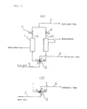
- the illustrated embodiment relates to a pressure-swing type gas separator system, which comprises two adsorption vessels 1 and 2 respectively containing adsorbent as shown in Fig. 1, and as will be described in detail in the following, provision is made such that adsorption may be effected in one of the adsorption vessels, while desorption may be effected in the other adsorption vessel, and they may be sequentially and alternately repeated.
- the bottom portion of the adsorption vessel 1 is connected to a rotary type switching valve 3 which consists of a four-port rotary valve, and exhaust lines 1 and 2b respectively connected to the top portions of the adsorption vessels 1 and 2 and respectively including stop valves 4, are connected to a common refined gas line 7.
- a rotary type switching valve 3 which consists of a four-port rotary valve, and exhaust lines 1 and 2b respectively connected to the top portions of the adsorption vessels 1 and 2 and respectively including stop valves 4, are connected to a common refined gas line 7.
- the above-described rotary type switching valve 3 comprises a fixed valve body 11 of circular shape in cross-section, a disc 10 rotatable about the center axis of the same valve body 11 via a rotary center pin 12, and a top cover 11' covering the disc 10 and fixed to the valve body 11.
- valve body 11 is provided with four ports P, 1a, E and 2a of L-shape in cross-section, which open on its circumferential surface at equal intervals, that is, at the positions angularly spaced by 90 about the rotary center pin 12, and also which extend radially inwards within the valve body 11 and then open at the top of the valve body 11.
- the disc 10 there are provided two circular-arc-shaped slots 10a and 10b extending in the angular range of 90 about the rotary center pin 12 and disposed at opposite side positions with respect to the rotary center pin 12 so that they can communicate the openings at the top of the valve body 11 of the adjacent ones of the above-described ports P, l a, E and 2a.
- the openings at the circumference of the valve body 11 of the aforementioned ports P, 1 a, E and 2a are connected respectively to a raw gas line 5 under a pressurized condition, the bottom of the adsorption vessel 1, an exhaust gas line 6 under a reduced-pressure condition, and the bottom of the adsorption vessel 2.
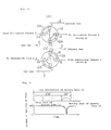
- a shaft 10c extending upwards and penetrating the top cover 11', at the upper portion of the same shaft 10c is mounted a Geneva gear 13, and this Geneva gear 13 is meshed with a Geneva gear 14 which is rotationally driven by a motor 15 rotating at a constant speed via speed reduction gears 16.
- the Geneva gear 13 is provided with four recesses 13a each having a circular-arc-shaped periphery and four grooves 13b directed in the radial direction and opening outwards at the positions between the adjacent recesses 13a.
- the Geneva gear 14 has a circular main body 14c and an arm 14a extending outwards, it is disposed in such manner that its lower surface may be positioned a little above the upper surface of the Geneva gear 13, and an engaging portion 14b at the tip end of the arm 14a is adapted to engage with and slide along the groove 13b of the Geneva gear 13. Accordingly, when the Geneva gear 14 is rotated in the direction of an arrow in Fig.
- the Geneva gear 3 by the motor 15 via the speed reduction gears 16, during the period of 1/4 revolutions of the Geneva gear 14 when the engaging portion 14b of the arm 14a of the Geneva gear 14 engages with the groove 13b of the Geneva gear 13, the Geneva gear 3 rotates by 90 about its center axis, and during the period of 3/4 revolutions of the Geneva gear 14 when the engaging portion 14b of the above-mentioned arm 14a disengages from the above-mentioned groove 13b, the Geneva gear 13 stops.
- the disc 10 in the switching valve 3 is rotated intermittently each time by 90 by the motor 15 via the Geneva gears 13 and 14. Accordingly, at a given time, the circular-arc-shaped grooves 10a and 10b take the state A shown at (a) in Fig. 4, subsequently they transfer to the state B shown at (b) in Fig. 4, and these states A and B are sequentially and alternately repeated.
- the port P and the port 1 a in the valve body 11 are communicated by the circular-arc-shaped groove 10b, hence the raw gas under a pressurized condition is introduced to the adsorption vessel 1 through the port P and the port l a, and after adsorptive component gas in the raw gas has been adsorbed by the adsorbent in the same vessel 1, refined gas is derived from a gas line 7 through the exhaust gas line 1 b in which the stop valve 4 is opened.
- the port E and the port 2a in the valve body 11 are communicated via the circular-arc-shaped groove 10a, hence the inside of the adsorption vessel 2 is connected to the exhaust gas line 6 under a reduced-pressure condition, thus the inside of the adsorption vessel 2 is reduced in pressure, the adsorbed gas is desorbed from the adsorbent to be exhausted to the exhaust gas line 6, and regeneration of the adsorbent is effected. It is to be noted that at this time the stop valve 4 in the exhaust line 2b of the adsorption vessel 2 is kept closed.
- Fig. 6 shows swinging of the pressures in the respective adsorption vessels 1 and 2 and the connecting conditions of the respective ports under the state A and under the state B in the illustrated embodiment.
- Fig. 5 shows a relation between the moving and stopping conditions of the Geneva gear 13 caused by the Geneva gear 14 and the extent of opening of the port resulted from the movement of the Geneva gears 13 and 14.
- the adsorption vessels 1 and 2 can be selectively connected to the raw gas line 5 or the exhaust gas line 6 by means of the circular-arc-shaped grooves 10a and 10b in the disc 10, and hence it is possible to cause adsorptive gas in the raw gas to be adsorbed by the adsorbent within the adsorption vessels and to cause adsorbed gas to be desorbed from the adsorbent to perform regeneration of the adsorbent.
- the switching valve 3 since the disc 10 of the rotary type switching valve 3 performs switching of ports in the above-described manner by being rotationally driven intermittently by the constant-speed motor 15 via the Geneva gears 13 and 14, the switching valve 3 can be designed to have a large bore diameter, its life is long, and it does not necessitate control air or the like. Furthermore, in this preferred embodiment, a necessary time interval of opening and closing of the valve can be easily preset.
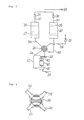
- Fig. 7 is a general view of a pressure-swing adsorption type gas separator system
- Fig. 8 is a cross-section view of a four-port rotary valve
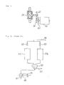
- Fig. 9 is an enlarged view showing a relation between a motor for a pressurizing pump and a four-port rotary valve.
- Air which is gas to be processed, is introduced into an air pump 21 via an intake pipe 32, then pressurized, and sent through a pump outlet pipe 33 into a four-port rotary valve 26.
- the four-port rotary valve 26 includes four openings and a rotor having a structure adapted to communicate adjacent two openings, as shown in Fig. 8. As shown in Fig.
- a speed reduction gear 25 is mounted to the shaft of this rotor, and a drive gear 24 is mounted to the shaft of the motor 22 for driving the air pump 21. Since the driving torque of the motor 22 for the air pump 21 is transmitted to the four-port rotary valve 26 as reduced in speed by meshing the drive gear 24 with the speed reduction gear 25, the air pump 21 and the four-port rotary valve 26 rotate as interlocked with each other. In other words, during the period when the air pump 21 is operating, the four-port rotary valve 26 is also always rotating. And by determining a speed reduction ratio by appropriately selecting the numbers of teeth of the drive gear 24 and the speed reduction gear 25, the timing of switching of the four-port rotary valve 26 can be determined depending upon a feed rate of air.
- an outlet pipe 33 of the air pump 21 is connected to a conduit 34 of an adsorption tower 27, hence air pressurized by the air pump 21 is introduced to the adsorption tower 27, nitrogen gas in the air is adsorbed by granular nitrogen adsorbent within the tower 27, and a non-adsorptive component of oxygen gas flows from an outlet pipe 37 through a check valve 30 and is collected as condensed oxygen gas 38.
- an adsorption tower 28 has its conduit 35 at the bottom connected to a nitrogen gas exhaust pipe 36 via the four-port rotary valve 26, and further communicates with the outside of the system held at the atmospheric pressure via a check valve 31. Accordingly, nitrogen gas kept adsorbed by the nitrogen adsorbent 27 within the adsorption tower 28 is desorbed under a reduced pressure and exhausted to the outside of the system.
- flow passages of the adsorption towers can be switched in the sequence of adsorption-regeneration-adsorption depending upon a feed amount of air to the adsorption towers, and so, it has become possible to continuously perform predetermined separation by adsorption regardless of variation of a capability of an air pump caused by voltage variation or the like.
- the non-adsorptive component gas forming the product gas can be collected without lowering its concentration.
- associated equipments such as a motor for driving the four-port rotary valve, a sequencer, a timer or a micro-computer for controlling the motor can be omitted, and so, a cost of the system is also reduced.
Abstract
The known pressure-swing adsorption type gas separator system, in which two adsorption vessels and two switching valves for respectively switching the two adsorption vessels selectively to a raw gas source and to an exhaust gas side, and the adsorption vessels are alternately switched between a pressurized adsorption step of process and a reduced-pressure desorption step of process by switching of the switching valves to perform separation of gases, is improved so as to make it possible to use a switching valve having a large bore diameter well adapted to a flow rate of raw gas, to reduce a number of switching valves, to simplify separator system, to facilitate operations of a switching valve at a high frequency, and to prolong a life of a switching valve. The improvements reside in that the switching valve is composed of a four-port rotary valve (3) having four ports (P, E, 1 a, 2a) connected to two adsorption vessels (1, 2), a raw gas source (5) and an exhaust gas side (7) and driven by a rotary drive source (15) for switching the two adsorption vessels (1, 2) selectively to the raw gas source (5) and to the exhaust gas side (7). Preferably, as the rotary drive source for the four-port rotary valve (26), a drive motor (22) for a pressurizing pump (21) provided in a raw gas line is commonly used, and the four-port rotary valve (26) is connected to the drive motor (22) via speed reduction means (25).
Description
- The present invention relates to a pressure-swing adsorption type gas separator system which is suitable for practicing a process of separating, for instance, oxygen gas and nitrogen gas from air.
- One example of a pressure-swing adsorption type gas separator system in the prior art is schematically shown in Fig. 10. In this system, raw gas is intermittently fed to a plurality of adsorption vessels 41 A and 41 B each accommodating adsorbent to be adsorbed thereby and to obtain refined gas having passed through the adsorption vessels 41 A and 41 B, also while interrupting the above-mentioned feeding of the raw gas, the gas adsorbed by the adsorbent is desorbed from the adsorbent and exhausted, and thereby the raw gas is refined and separated. In this gas separator system, directions of flows of gases are switched at a high frequency, and for the purpose of direction control for these flows of gases,
switching valves 42A and 42B consisting of electromagnetic valves, pneumatically operable valves or the like are employed. - Also, another example of a pressure-swing adsorption type gas separator system in the prior art, which was designed to work for separating air, is schematically shown in Fig. 11. In this system, air which is gas to be processed, is pressurized by an
air pump 51, then it is introduced into anadsorption tower electromagnetic valve 52, thus nitrogen in the air is adsorbed by nitrogen adsorbent within the adsorption tower, and concentratedoxygen gas 56 is collected via acheck valve 55. On the other hand, anadsorption tower exhaust gas system 57 held at the atmospheric pressure via the five-portelectromagnetic valve 52, and nitrogen adsorbed within theadsorption tower exhaust gas system 57. The switching between the pressurized adsorption step of process and the reduced-pressure desorption-reproduction step of process is effected by driving the five-portelectromagnetic valve 52 by feeding an electric current to an electromagnetic coil. It is to be noted that theair pump 51 is driven by amotor 58, and thismotor 58 is associated with acooling fan 59. - However, in the above-described gas separator systems in the prior art, as a switching valve for raw gas flowing at a large flow rate an electromagnetic valve having a large bore diameter is necessitated, and this would be a valve generating a large electromagnetic force. Alternatively, if a different system, in which a pneumatically operable valve having an electromagnetic valve for switching operations is separately provided, is employed, then there is a shortcoming that the system becomes complex and control air (or pressure) becomes necessary. Furthermore, the above-mentioned electro-magnetic valve or the electromagnetic valve for switching operations cannot be expected to have a long life time because they are required to perform switching of opening/closing at a high frequency.
- On the other hand, in the gas separator system shown in Fig. 11, as switching means for gas flows, a fiveport electromagnetic valve is provided on the feed side of gas to be processed of an absorption tower, and at every predetermined period the five- port electromagnetic valve is switched as controlled by a sequencer, a timer, a micro-computer or the like. However, this system involved the problem that according to this method, if a voltage should vary during an operation of the system, a capability of an air pump would vary regardless of whether an A.C. motor is used or a D.C. motor is used, and for instance, if a voltage should lower, then due to lowering of an outlet pressure of the air pump, a feed amount of air would be reduced, hence the pressure in the absorption tower cannot be raised up to a predetermined pressure within a fixed time, and an oxygen concentration of product gas would be lowered.
- A principal object of the present invention is to provide a pressure-swing adsorption type gas separator system, which has resolved the above-described problems involved in the heretofore known gas separator system, which does not necessitate an electromagnetic valve exerting a large electromagnetic force, and which can maintain a long life even under switching operations at a high frequency.
- A more specific object of the present invention is to provide a pressure-swing adsorption type gas separator system, which is free from the shortcomings of the gas separator system in the prior art, and in which switching between adsorption and regeneration is effected without relying upon the method of switching at every predetermined period by making use of a sequencer, a timer or a micro-computer, the operation can be switched to a regeneration step of process after the pressure in an adsorption tower has been grown to a predetermined pressure, and thereby lowering of a concentration of product gas can be avoided.
- According to one feature of the present invention, there is provided a pressure-swing adsorption type gas separator system provided with two adsorption vessels and switching valves for respectively switching the two adsorption vessels selectively to a raw gas source and to an exhaust gas side, in which the two adsorption vessels are alternately switched between a pressurized adsorption step of process and a reduced-pressure desorption step of process by switching the switching valves to perform separation of gases; improved in that the switching valve is composed of four-port rotary valve having four connection ports connected to two adsorption vessels, a raw gas source and an exhaust gas side and driven by a rotary drive source for switching the two adsorption vessels selectively to the raw gas source and to the exhaust gas side.
- According to another feature of the present invention, there is provided the above-featured gas separator system, further improved in that the four-port rotary valve is connected to a rotary drive source via an intermittent rotary transmission device.
- According to still another feature of the present invention, there is provided the last-featured gas separator system, further improved in that the intermittent rotary transmission system is formed of a gear type intermittent rotary transmission device making use of Geneva gears.
- According to yet another feature of the present invention, there is provided the first-featured gas separator system, further improved in that as the rotary drive source for the four-port rotary valve, a drive motor for a pressurizing pump provided in a raw gas line is commonly used, and the four-port rotary valve is connected to the drive motor via speed-reduction means.
- According to a further feature of the present invention, there is provided the just-featured gas separator system, further improved in that the speed reduction means is composed of speed reduction gears.
- As described above, according to the present invention, owing to the above-described structural features, switching between connections of a raw gas source to one adsorption vessel and the other adsorption vessel to the exhaust gas side and the reverse connections is successively and alternately repeated by means of a four-port rotary valve rotationally driven by a rotary drive source. More particularly, a raw gas source is connected to one adsorption vessel via a four-port rotary valve, hence raw gas is introduced into the adsorption vessel, in which an adsorptive component is adsorbed by adsorbent, while the other adsorption vessel is connected to an exhaust gas side, hence the gas component adsorbed by the adsorbent is desorbed and exhausted to the exhaust gas side, and the adsorbent is regenerated.
- Since the switching valve used in the system according to the present invention is of rotary type and is driven by a rotating drive source as described above, the valve can be designed so as to have a large bore diameter, has a long life, and does not necessitate air for control purpose and the like.
- In addition, in the gas separator system according to the present invention, since this four-port rotary valve is connected to a motor for a pressurizing pump via speed reduction means, it is possible to make a raw gas feed amount of the pressurizing pump and the rotary angle of the four-port rotary valve proportional to each other, and if a speed reduction ratio of the speed reduction means is appropriately preset, switching of the four-port rotary valve can be completed at the time point when a predetermined amount of raw gas has been fed. According to this method, since the four-port rotary valve can be switched in accordance to a feed amount of raw gas even if a rotational speed of a pressurizing pump is varied due to variation of a voltage, the final pressure of an adsorption step of process can be made a predetermined value, and so, lowering of a concentration of collected gas can be obviated.
- The above-mentioned and other objects, features and advantages of the present invention will become more apparent by reference to the following description of preferred embodiments of the present invention taken in conjunction with the accompanying drawings.
- In the accompanying drawings:
- Fig. 1 is a system diagram of one preferred embodiment of the present invention, in which different states of connection of a switching valve are shown at (a) and at (b), respectively;
- Fig. 2 is a schematic view partially in cross-section of a drive mechanism for the switching valve in the same preferred embodiment;
- Fig. 3 is a schematic view of Geneva gears used in the same preferred embodiment;
- Fig. 4 is a schematic view illustrating operations of the switching valve used in the same preferred embodiment, in which different states of the switching valve including a switching disc placed at different positions are shown at (a) and at (b), respectively;
- Fig. 5 is a diagram showing a relation between moving and stopping states of Geneva gears and an extent of opening of a port of the switching valve by the switching disc depending upon the state of the Geneva gears;
- Fig. 6 is a diagram showing a relation between pressure swings in the respective adsorption vessels and states of connection of the switching valve ports;
- Fig. 7 is a system diagram of a pressure-swing adsorption type air separator according to another preferred embodiment of the present invention;
- Fig. 8 is a cross-section view of a four-port rotary valve used in the second preferred embodiment shown in Fig. 7;
- Fig. 9 is an enlarged schematic cross-section view showing a relation between a motor for driving an air pump and the four-port rotary valve in the same preferred embodiment;
- Fig. 10 is a system diagram of a gas separator system in the prior art; and
- Fig. 11 is a system diagram of another pressure-swing type air separator system in the prior art.
- Now one preferred embodiment of the present invention will be described with reference to Figs. 1 to 6. The illustrated embodiment relates to a pressure-swing type gas separator system, which comprises two
adsorption vessels - The bottom portion of the
adsorption vessel 1 is connected to a rotarytype switching valve 3 which consists of a four-port rotary valve, andexhaust lines adsorption vessels stop valves 4, are connected to a common refinedgas line 7. - As shown in Fig. 2, the above-described rotary
type switching valve 3 comprises afixed valve body 11 of circular shape in cross-section, adisc 10 rotatable about the center axis of thesame valve body 11 via arotary center pin 12, and a top cover 11' covering thedisc 10 and fixed to thevalve body 11. - As shown in Figs. 2 and 4, the above-mentioned
valve body 11 is provided with four ports P, 1a, E and 2a of L-shape in cross-section, which open on its circumferential surface at equal intervals, that is, at the positions angularly spaced by 90 about therotary center pin 12, and also which extend radially inwards within thevalve body 11 and then open at the top of thevalve body 11. On the other hand, in thedisc 10 are provided two circular-arc-shaped slots rotary center pin 12 and disposed at opposite side positions with respect to therotary center pin 12 so that they can communicate the openings at the top of thevalve body 11 of the adjacent ones of the above-described ports P, l a, E and 2a. - The openings at the circumference of the
valve body 11 of the aforementioned ports P, 1 a, E and 2a are connected respectively to araw gas line 5 under a pressurized condition, the bottom of theadsorption vessel 1, anexhaust gas line 6 under a reduced-pressure condition, and the bottom of theadsorption vessel 2. - In addition, as shown in Fig. 2, at the center of the
disc 10 is provided a shaft 10c extending upwards and penetrating the top cover 11', at the upper portion of the same shaft 10c is mounted a Genevagear 13, and this Genevagear 13 is meshed with a Genevagear 14 which is rotationally driven by amotor 15 rotating at a constant speed viaspeed reduction gears 16. - As shown in Fig. 3, the Geneva
gear 13 is provided with fourrecesses 13a each having a circular-arc-shaped periphery and fourgrooves 13b directed in the radial direction and opening outwards at the positions between theadjacent recesses 13a. The Genevagear 14 has a circular main body 14c and an arm 14a extending outwards, it is disposed in such manner that its lower surface may be positioned a little above the upper surface of the Genevagear 13, and an engaging portion 14b at the tip end of the arm 14a is adapted to engage with and slide along thegroove 13b of the Genevagear 13. Accordingly, when the Genevagear 14 is rotated in the direction of an arrow in Fig. 3 by themotor 15 via thespeed reduction gears 16, during the period of 1/4 revolutions of the Genevagear 14 when the engaging portion 14b of the arm 14a of the Genevagear 14 engages with thegroove 13b of the Genevagear 13, the Genevagear 3 rotates by 90 about its center axis, and during the period of 3/4 revolutions of the Genevagear 14 when the engaging portion 14b of the above-mentioned arm 14a disengages from the above-mentionedgroove 13b, the Genevagear 13 stops. - In the illustrated embodiment, the
disc 10 in theswitching valve 3 is rotated intermittently each time by 90 by themotor 15 via the Genevagears shaped grooves - Under the state A, the port P and the port 1 a in the
valve body 11 are communicated by the circular-arc-shaped groove 10b, hence the raw gas under a pressurized condition is introduced to theadsorption vessel 1 through the port P and the port l a, and after adsorptive component gas in the raw gas has been adsorbed by the adsorbent in thesame vessel 1, refined gas is derived from agas line 7 through theexhaust gas line 1 b in which thestop valve 4 is opened. On the other hand, the port E and the port 2a in thevalve body 11 are communicated via the circular-arc-shaped groove 10a, hence the inside of theadsorption vessel 2 is connected to theexhaust gas line 6 under a reduced-pressure condition, thus the inside of theadsorption vessel 2 is reduced in pressure, the adsorbed gas is desorbed from the adsorbent to be exhausted to theexhaust gas line 6, and regeneration of the adsorbent is effected. It is to be noted that at this time thestop valve 4 in theexhaust line 2b of theadsorption vessel 2 is kept closed. - Under the state B, on the contrary, raw gas is introduced into the
adsorption vessel 2 to obtain refined gas, and regeneration of the adsorbent within theadsorption vessel 1 is effected. - Fig. 6 shows swinging of the pressures in the
respective adsorption vessels - Fig. 5 shows a relation between the moving and stopping conditions of the Geneva
gear 13 caused by the Genevagear 14 and the extent of opening of the port resulted from the movement of the Genevagears - As described above, in the illustrated embodiment, by intermittently rotating the
disc 10 by themotor 15 via the speed reduction gears 16 and the Geneva gears 13 and 14, theadsorption vessels raw gas line 5 or theexhaust gas line 6 by means of the circular-arc-shapedgrooves disc 10, and hence it is possible to cause adsorptive gas in the raw gas to be adsorbed by the adsorbent within the adsorption vessels and to cause adsorbed gas to be desorbed from the adsorbent to perform regeneration of the adsorbent. - Also, in the illustrated embodiment since the
disc 10 of the rotarytype switching valve 3 performs switching of ports in the above-described manner by being rotationally driven intermittently by the constant-speed motor 15 via the Geneva gears 13 and 14, the switchingvalve 3 can be designed to have a large bore diameter, its life is long, and it does not necessitate control air or the like. Furthermore, in this preferred embodiment, a necessary time interval of opening and closing of the valve can be easily preset. - While circumscribing type Geneva gears 13 and 14 were employed in the above-described embodiment, these could be designed as inscribing type Geneva gears, or in place of the Geneva gears, other intermittent rotation transmission means such as a ratchet drive including a ratchet wheel and a pressure claw, an intermittent gearing in which teeth of one of gears meshed with each other are partly removed, or the like could be employed.
- The above-described embodiment of the present invention can achieve the following effects:
- (1) A directional switching valve can be formed as a valve having a sufficiently large bore diameter which can be adapted to a flow rate of raw gas.
- (2) A number of switching valves can be reduced as compared to a pneumatically operated valve.
- (3) Since high-pressure air for operation is unnecessary, the system is simplified.
- (4) Highly frequent opening/closing operations by means of a directional switching valve are easy, and also a life of the valve can be prolonged.
- Next, another preferred embodiment of the present invention will be explained with reference to Figs. 7 to 9.
- Fig. 7 is a general view of a pressure-swing adsorption type gas separator system, Fig. 8 is a cross-section view of a four-port rotary valve, and Fig. 9 is an enlarged view showing a relation between a motor for a pressurizing pump and a four-port rotary valve. Air, which is gas to be processed, is introduced into an air pump 21 via an
intake pipe 32, then pressurized, and sent through apump outlet pipe 33 into a four-port rotary valve 26. The four-port rotary valve 26 includes four openings and a rotor having a structure adapted to communicate adjacent two openings, as shown in Fig. 8. As shown in Fig. 9, aspeed reduction gear 25 is mounted to the shaft of this rotor, and adrive gear 24 is mounted to the shaft of themotor 22 for driving the air pump 21. Since the driving torque of themotor 22 for the air pump 21 is transmitted to the four-port rotary valve 26 as reduced in speed by meshing thedrive gear 24 with thespeed reduction gear 25, the air pump 21 and the four-port rotary valve 26 rotate as interlocked with each other. In other words, during the period when the air pump 21 is operating, the four-port rotary valve 26 is also always rotating. And by determining a speed reduction ratio by appropriately selecting the numbers of teeth of thedrive gear 24 and thespeed reduction gear 25, the timing of switching of the four-port rotary valve 26 can be determined depending upon a feed rate of air. - Under the condition shown in Fig. 7, an
outlet pipe 33 of the air pump 21 is connected to aconduit 34 of anadsorption tower 27, hence air pressurized by the air pump 21 is introduced to theadsorption tower 27, nitrogen gas in the air is adsorbed by granular nitrogen adsorbent within thetower 27, and a non-adsorptive component of oxygen gas flows from anoutlet pipe 37 through acheck valve 30 and is collected as condensedoxygen gas 38. - On the other hand, an adsorption tower 28 has its
conduit 35 at the bottom connected to a nitrogengas exhaust pipe 36 via the four-port rotary valve 26, and further communicates with the outside of the system held at the atmospheric pressure via acheck valve 31. Accordingly, nitrogen gas kept adsorbed by thenitrogen adsorbent 27 within the adsorption tower 28 is desorbed under a reduced pressure and exhausted to the outside of the system. When a fixed amount of air has been fed to theadsorption tower 27 and a predetermined pressurized condition has been realized, a rotor of the four-port rotary valve 26 interlocked with rotation of the air pump 21 is rotated by 90°, then theoutlet pipe 33 of the air pump 21 is connected to theconduit 35, theconduit 34 of theadsorption tower 27 is connected to the nitrogengas exhaust pipe 36, and thus switching of flow passages between a pressurized adsorption step of process and a reduced pressure desorptionregeneration step of process is completed. - As described above, by making use of the drive source for the air pump to simultaneously rotate the four-port rotary valve, flow passages of the adsorption towers can be switched in the sequence of adsorption-regeneration-adsorption depending upon a feed amount of air to the adsorption towers, and so, it has become possible to continuously perform predetermined separation by adsorption regardless of variation of a capability of an air pump caused by voltage variation or the like.
- By employing the above-described construction, it is possible to rotate a four-port rotary valve for use in switching of flow passages of adsorption towers as interlocked with a drive source for a pump for pressurizing gas to be processed, and it is possible to finish an adsorption step of process depending upon a feed amount of gas to be processed to the adsorption towers. Therefore, even if a feed rate of the gas to be processed should be reduced as a result of voltage variations, frequency variations or the like, since the rotary speed of the four-port rotary valve is lowered depending upon the reduction of the feed rate and the cycle time is prolonged, the pressure in the adsorption tower would rise automatically until a predetermined pressure is established. Consequently, the non-adsorptive component gas forming the product gas can be collected without lowering its concentration. In addition, associated equipments such as a motor for driving the four-port rotary valve, a sequencer, a timer or a micro-computer for controlling the motor can be omitted, and so, a cost of the system is also reduced.
- Since many changes and modifications can be made to the above-described constructions without departing from the spirit of the present invention, it is intended that all matter contained in the above- description and illustrated in the accompanying drawings shall be interpreted to be illustrative and not in a limiting sense.
Claims (5)
1. A pressure-swing adsorption type gas separator system provided with two adsorption vessels and switching valves for respectively switching said two adsorption vessels selectively to a raw gas source and to an exhaust gas side, in which the two adsorption vessels are alternately switched between a pressurized adsorption step of process and a reduced-pressure desorption step of process by switching of said switching valves to perform separation of gases; characterized in that said switching valve is composed of a four-port rotary valve (3, 26) having four connection ports connected to two adsorption vessels (1, 2; 27, 28), a raw gas source and an exhaust gas side and driven by a rotary drive source (15, 22) for switching the two adsorption vessels selectively to the raw gas source and to the exhaust gas side.
2. A pressure-swing adsorption type gas separator system as claimed in Claim 1, further characterized in that said four-port rotary valve (3) is connected to a rotary drive source via an intermittent rotary transmission device (13, 14).
3. A pressure-swing adsorption type gas separator system as claimed in Claim 2, further characterized in that said intermittent rotary transmission device is formed of a gear type intermittent rotary transmission device making use of Geneva gears (13, 14).
4. A pressure-swing adsorption type gas separator system as claimed in Claim 1, further characterized in that as the rotary drive source for said four-port rotary valve (26), a drive motor (22) for a pressurizing pump (21) provided in a raw gas line is commonly used, and said four-port rotary valve (26) is connected to said drive motor (22) via speed-reduction means (24, 25).
5. A pressure-swing adsorption type gas separator system as claimed in Claim 4, further characterized in that said speed-reduction means is composed of speed-reduction gears (24, 25).
Applications Claiming Priority (4)
| Application Number | Priority Date | Filing Date | Title |
|---|---|---|---|
| JP192979/91 | 1991-08-01 | ||
| JP3192979A JPH0531318A (en) | 1991-08-01 | 1991-08-01 | Gas separator |
| JP3232757A JP2948367B2 (en) | 1991-09-12 | 1991-09-12 | Gas separation equipment |
| JP232757/91 | 1991-09-12 |
Publications (1)
| Publication Number | Publication Date |
|---|---|
| EP0525521A1 true EP0525521A1 (en) | 1993-02-03 |
Family
ID=26507626
Family Applications (1)
| Application Number | Title | Priority Date | Filing Date |
|---|---|---|---|
| EP92112115A Withdrawn EP0525521A1 (en) | 1991-08-01 | 1992-07-15 | Gas separator system |
Country Status (4)
| Country | Link |
|---|---|
| US (1) | US5256174A (en) |
| EP (1) | EP0525521A1 (en) |
| KR (1) | KR950012522B1 (en) |
| AU (1) | AU638898B2 (en) |
Cited By (5)
| Publication number | Priority date | Publication date | Assignee | Title |
|---|---|---|---|---|
| WO1994027708A1 (en) * | 1993-06-01 | 1994-12-08 | Ppv Verwaltungs Ag | Rotary slide valve |
| EP0743087A1 (en) * | 1995-05-19 | 1996-11-20 | L'air Liquide, Societe Anonyme Pour L'etude Et L'exploitation Des Procedes Georges Claude | Device and process for gas separation by adsorption |
| GB2310916A (en) * | 1996-03-05 | 1997-09-10 | Lucas Ind Plc | Distributor arrangement |
| US5785740A (en) * | 1995-05-19 | 1998-07-28 | L'air Liquide, Societe Anonyme Pour L'etude Et L'exploitation Des Procedes Georges Claude | Device and process for the separation of gas by adsorption |
| EP1992396A1 (en) | 2007-05-15 | 2008-11-19 | Air Products and Chemicals, Inc. | Containerized gas separation system |
Families Citing this family (51)
| Publication number | Priority date | Publication date | Assignee | Title |
|---|---|---|---|---|
| US5681376A (en) * | 1995-11-07 | 1997-10-28 | Calgon Carbon Corporation | Rotating flow distributor assembly for use in continuously distributing decontamination and regeneration fluid flow |
| US6063161A (en) | 1996-04-24 | 2000-05-16 | Sofinoy Societte Financiere D'innovation Inc. | Flow regulated pressure swing adsorption system |
| USRE38493E1 (en) * | 1996-04-24 | 2004-04-13 | Questair Technologies Inc. | Flow regulated pressure swing adsorption system |
| US5891217A (en) * | 1997-01-21 | 1999-04-06 | The Boc Group, Inc. | Process and apparatus for gas separation |
| US5820656A (en) * | 1997-01-21 | 1998-10-13 | The Boc Group, Inc. | Process and apparatus for gas separation |
| US6152163A (en) * | 1998-04-23 | 2000-11-28 | United Dominion Industries, Inc. | Switching valve for multi-chamber adsorbent air and gas fractionation system |
| US6921597B2 (en) | 1998-09-14 | 2005-07-26 | Questair Technologies Inc. | Electrical current generation system |
| US6143056A (en) * | 1998-11-19 | 2000-11-07 | Praxair Technology, Inc. | Rotary valve for two bed vacuum pressure swing absorption system |
| US6253778B1 (en) | 1998-11-19 | 2001-07-03 | Praxair Technology, Inc. | Rotary valve |
| WO2000074819A1 (en) | 1999-06-04 | 2000-12-14 | Flair Corporation | Rotating drum adsorber process and system |
| US7041272B2 (en) | 2000-10-27 | 2006-05-09 | Questair Technologies Inc. | Systems and processes for providing hydrogen to fuel cells |
| CA2325072A1 (en) * | 2000-10-30 | 2002-04-30 | Questair Technologies Inc. | Gas separation for molten carbonate fuel cell |
| US7097925B2 (en) | 2000-10-30 | 2006-08-29 | Questair Technologies Inc. | High temperature fuel cell power plant |
| AU2002215752A1 (en) * | 2000-12-08 | 2002-06-18 | Denis Connor | Methods and apparatuses for gas separation by pressure swing adsorption with partial gas product feed to fuel cell power source |
| CA2329475A1 (en) * | 2000-12-11 | 2002-06-11 | Andrea Gibbs | Fast cycle psa with adsorbents sensitive to atmospheric humidity |
| WO2002071463A1 (en) * | 2001-03-02 | 2002-09-12 | Tokyo Electron Limited | Shower head gas injection apparatus with secondary high pressure pulsed gas injection |
| DE10148931A1 (en) * | 2001-10-04 | 2003-04-24 | Eugster Frismag Ag Romanshorn | Espresso machine with a rotary, ceramic disc valve as a selective water / steam distributor |
| CA2476409A1 (en) | 2002-03-14 | 2003-09-18 | Questair Technologies Inc. | Hydrogen recycle for solid oxide fuel cell |
| CA2477262A1 (en) | 2002-03-14 | 2003-09-18 | Questair Technologies Inc. | Gas separation by combined pressure swing and displacement purge |
| US7285350B2 (en) | 2002-09-27 | 2007-10-23 | Questair Technologies Inc. | Enhanced solid oxide fuel cell systems |
| US20040197616A1 (en) * | 2003-04-01 | 2004-10-07 | Edlund David J. | Oxidant-enriched fuel cell system |
| US6936091B2 (en) * | 2003-09-17 | 2005-08-30 | Metso Automation Usa, Inc. | System and method for treating fluid using a multi-port valve assembly |
| US7276107B2 (en) * | 2003-12-23 | 2007-10-02 | Praxair Technology, Inc. | Indexing rotary dual valve for pressure swing adsorption systems |
| US7443803B2 (en) * | 2004-03-23 | 2008-10-28 | Fujitsu Limited | Estimating and managing network traffic |
| US7189280B2 (en) | 2004-06-29 | 2007-03-13 | Questair Technologies Inc. | Adsorptive separation of gas streams |
| US7445663B1 (en) * | 2004-10-21 | 2008-11-04 | Sunrise Medical Hhg Inc. | Energy efficient oxygen concentrator |
| US7828877B2 (en) | 2004-11-05 | 2010-11-09 | Xebec Adsorption, Inc. | Separation of carbon dioxide from other gases |
| US7354464B2 (en) * | 2004-12-17 | 2008-04-08 | Texaco Inc. | Apparatus and method for producing hydrogen |
| US7892304B2 (en) * | 2004-12-17 | 2011-02-22 | Texaco Inc. | Apparatus and method for controlling compressor motor speed in a hydrogen generator |
| US7402287B2 (en) * | 2004-12-17 | 2008-07-22 | Texaco Inc. | Apparatus and methods for producing hydrogen |
| US7354463B2 (en) * | 2004-12-17 | 2008-04-08 | Texaco Inc. | Apparatus and methods for producing hydrogen |
| US7833311B2 (en) * | 2004-12-20 | 2010-11-16 | Idatech, Llc | Temperature-based breakthrough detection and pressure swing adsorption systems and fuel processing systems including the same |
| US7393382B2 (en) * | 2004-12-20 | 2008-07-01 | Idatech Llc | Temperature-based breakthrough detection and pressure swing adsorption systems and fuel processing systems including the same |
| US7399342B2 (en) | 2004-12-22 | 2008-07-15 | Idatech, Llc | Systems and methods for regulating heating assembly operation through pressure swing adsorption purge control |
| US7964176B2 (en) * | 2005-03-29 | 2011-06-21 | Chevron U.S.A. Inc. | Process and apparatus for thermally integrated hydrogen generation system |
| US7854793B2 (en) | 2006-06-30 | 2010-12-21 | David Lester Rarig | Pressure swing adsorption system with indexed rotatable multi-port valves |
| US8551444B2 (en) * | 2006-10-27 | 2013-10-08 | Air Products And Chemicals, Inc. | Compact pressure swing reformer |
| US7837771B2 (en) * | 2007-10-12 | 2010-11-23 | Hamilton Sundstrand Corporation | Rotary cylinder dual diverter valve |
| US8070841B2 (en) * | 2007-12-12 | 2011-12-06 | Idatech, Llc | Systems and methods for supplying auxiliary fuel streams during intermittent byproduct discharge from pressure swing adsorption assemblies |
| US7837765B2 (en) | 2007-12-12 | 2010-11-23 | Idatech, Llc | Systems and methods for supplying auxiliary fuel streams during intermittent byproduct discharge from pressure swing adsorption assemblies |
| US20090165368A1 (en) * | 2007-12-28 | 2009-07-02 | Yunquan Liu | Process and apparatus for reforming gaseous and liquid fuels |
| US20090170967A1 (en) * | 2007-12-28 | 2009-07-02 | Lixin You | Concurrent oxidation and steam methane reforming process and reactor therefor |
| US8394154B2 (en) * | 2007-12-28 | 2013-03-12 | Texaco Inc. | Counter-current oxidation and steam methane reforming process and reactor therefor |
| ITMI20080115A1 (en) * | 2008-01-25 | 2009-07-26 | Polaris Srl | APPARATUS AND METHOD TO DISTRIBUTE A PLURALITY OF FLUID CURRENTS THROUGH A PLURALITY OF ROOMS, IN PARTICULAR TO IMPLEMENT PROCESS OF ADSORPTION. |
| US7989511B2 (en) * | 2008-05-21 | 2011-08-02 | Texaco Inc. | Process and apparatus for synthesis gas and hydrocarbon production |
| US7854794B2 (en) * | 2008-07-28 | 2010-12-21 | Barone Michael R | Rotary valve element for twin bed alternative treatment systems |
| CN102348490B (en) * | 2009-03-16 | 2014-01-22 | 电源开发工程技术株式会社 | Dry exhaust-gas treating apparatus |
| JP5291794B2 (en) * | 2009-03-16 | 2013-09-18 | ジェイパワー・エンテック株式会社 | Regeneration tower and dry exhaust gas treatment equipment |
| BR112012006823A2 (en) * | 2009-09-30 | 2019-09-24 | Koninl Philips Electronics Nv | gas concentration arrangement, gas concentration system and gas pump for gas pumping |
| FR3003326B1 (en) * | 2013-03-13 | 2015-08-21 | Valeo Systemes De Controle Moteur | DEVICE FOR NEEDLEING A FLUID FOR A VALVE HAVING AT LEAST THREE WAYS |
| US10843120B2 (en) | 2016-06-29 | 2020-11-24 | Koninklijke Philips N.V. | Rotary valve assembly for pressure swing adsorption system |
Citations (6)
| Publication number | Priority date | Publication date | Assignee | Title |
|---|---|---|---|---|
| GB481350A (en) * | 1937-03-10 | 1938-03-09 | Carbonisation Charbons Actifs | Improved arrangement of valves for use in controlling pipes or conduits in cyclical operations such as those of adsorption apparatus for the separation of gases |
| GB1168102A (en) * | 1966-07-13 | 1969-10-22 | Lloyd And Hillman Ltd | A Timing and Switching Valve Apparatus and an Apparatus for Processing Air or other Gas including the same |
| US4211291A (en) * | 1978-03-06 | 1980-07-08 | Smith International, Inc. | Drill fluid powered hydraulic system |
| US4870960A (en) * | 1985-10-07 | 1989-10-03 | Litton Systems, Inc. | Backup breathing gas supply for an oxygen concentrator system |
| US4925464A (en) * | 1988-11-17 | 1990-05-15 | Ryder International Corporation | Fluid flow switching valve assembly and system |
| US4989641A (en) * | 1989-10-11 | 1991-02-05 | Santa Fe Energy Co. | Rotary selector valve |
Family Cites Families (20)
| Publication number | Priority date | Publication date | Assignee | Title |
|---|---|---|---|---|
| US2237684A (en) * | 1939-07-31 | 1941-04-08 | Delaware Engineering Corp | Method of and apparatus for treating gases |
| US3016978A (en) * | 1958-01-09 | 1962-01-16 | Selas Corp Of America | Dehydrator |
| US3155471A (en) * | 1959-05-01 | 1964-11-03 | Ite Circuit Breaker Ltd | Dry air system for isolated phase bus |
| GB1144692A (en) * | 1965-03-12 | 1969-03-05 | Pall Corp | Gas drier with automatic cycle control and process |
| US4209308A (en) * | 1972-09-25 | 1980-06-24 | Blodgett Gerry A | Sorption system |
| US4127395A (en) * | 1976-10-18 | 1978-11-28 | Pall Corporation | Adsorbent fractionator with fail-safe automatic cycle control and process |
| US4162146A (en) * | 1977-12-14 | 1979-07-24 | Pall Corporation | Multi-chamber adsorbent gas fractionator with non-jamming effluent flow control valve |
| US4322223A (en) * | 1979-03-30 | 1982-03-30 | Pall Corporation | Adsorbent fractionators with electronic sequence timer cycle control and process |
| US4272265A (en) * | 1979-06-22 | 1981-06-09 | Essex Cryogenics Of Missouri, Inc. | Apparatus for pressure swing generation of oxygen |
| US4469494A (en) * | 1983-01-31 | 1984-09-04 | Kinetics Technology International Corporation | Disc operated gas purification system |
| JPS61147121A (en) * | 1984-12-20 | 1986-07-04 | Shimadzu Corp | Double beam spectrophotometer |
| GB2190014B (en) * | 1986-05-07 | 1990-04-11 | Boc Group Inc | Improved valving assembly for a pressure swing adsorption apparatus |
| US4698075A (en) * | 1986-06-05 | 1987-10-06 | International Oxygen Company, Inc. | Control system for fluid absorption systems and the like |
| EP0250235A1 (en) * | 1986-06-17 | 1987-12-23 | Negretti Aviation Limited | Improvements in and relating to pressure swing oxygen generating systems |
| JPS6331251A (en) * | 1986-07-24 | 1988-02-09 | Toshiba Corp | Telephone set |
| JPS6441732A (en) * | 1987-08-07 | 1989-02-14 | Toshiba Corp | Air conditioner with oxygen enriching air supplier device |
| US4787417A (en) * | 1987-11-24 | 1988-11-29 | Windsor Jr John F | Rotary pressure/purge valve |
| US4968334A (en) * | 1989-09-08 | 1990-11-06 | Hilton Thomas J | Remotely-controlled multi-port valve having a multi-vane rotating central drum element |
| US5112367A (en) * | 1989-11-20 | 1992-05-12 | Hill Charles C | Fluid fractionator |
| US5114441A (en) * | 1990-11-02 | 1992-05-19 | Ryder International Corporation | Oxygen concentrator system and valve structure |
-
1992
- 1992-07-15 EP EP92112115A patent/EP0525521A1/en not_active Withdrawn
- 1992-07-28 AU AU20625/92A patent/AU638898B2/en not_active Ceased
- 1992-08-01 KR KR1019920013890A patent/KR950012522B1/en not_active IP Right Cessation
- 1992-08-03 US US07/923,586 patent/US5256174A/en not_active Expired - Lifetime
Patent Citations (6)
| Publication number | Priority date | Publication date | Assignee | Title |
|---|---|---|---|---|
| GB481350A (en) * | 1937-03-10 | 1938-03-09 | Carbonisation Charbons Actifs | Improved arrangement of valves for use in controlling pipes or conduits in cyclical operations such as those of adsorption apparatus for the separation of gases |
| GB1168102A (en) * | 1966-07-13 | 1969-10-22 | Lloyd And Hillman Ltd | A Timing and Switching Valve Apparatus and an Apparatus for Processing Air or other Gas including the same |
| US4211291A (en) * | 1978-03-06 | 1980-07-08 | Smith International, Inc. | Drill fluid powered hydraulic system |
| US4870960A (en) * | 1985-10-07 | 1989-10-03 | Litton Systems, Inc. | Backup breathing gas supply for an oxygen concentrator system |
| US4925464A (en) * | 1988-11-17 | 1990-05-15 | Ryder International Corporation | Fluid flow switching valve assembly and system |
| US4989641A (en) * | 1989-10-11 | 1991-02-05 | Santa Fe Energy Co. | Rotary selector valve |
Cited By (11)
| Publication number | Priority date | Publication date | Assignee | Title |
|---|---|---|---|---|
| WO1994027708A1 (en) * | 1993-06-01 | 1994-12-08 | Ppv Verwaltungs Ag | Rotary slide valve |
| US5584322A (en) * | 1993-06-01 | 1996-12-17 | Ppv Verwaltungs Ag | Rotary slide valve |
| EP0743087A1 (en) * | 1995-05-19 | 1996-11-20 | L'air Liquide, Societe Anonyme Pour L'etude Et L'exploitation Des Procedes Georges Claude | Device and process for gas separation by adsorption |
| FR2734172A1 (en) * | 1995-05-19 | 1996-11-22 | Air Liquide | DEVICE AND METHOD FOR GAS SEPARATION BY ADSORPTION |
| US5679134A (en) * | 1995-05-19 | 1997-10-21 | L'air Liquide, Societe Anonyme Pour L'etude Et L'exploitation Des Procedes Georges Claude | Device and process for the separation of gas by adsorption |
| US5785740A (en) * | 1995-05-19 | 1998-07-28 | L'air Liquide, Societe Anonyme Pour L'etude Et L'exploitation Des Procedes Georges Claude | Device and process for the separation of gas by adsorption |
| EP1243306A2 (en) * | 1995-05-19 | 2002-09-25 | L'air Liquide, S.A. à Directoire et Conseil de Surveillance pour l'Etude et l'Exploitation des Procédés Georges Claude | Device and process for gas separation by adsorption |
| EP1243306A3 (en) * | 1995-05-19 | 2003-03-12 | L'air Liquide, S.A. à Directoire et Conseil de Surveillance pour l'Etude et l'Exploitation des Procédés Georges Claude | Device and process for gas separation by adsorption |
| GB2310916A (en) * | 1996-03-05 | 1997-09-10 | Lucas Ind Plc | Distributor arrangement |
| EP1992396A1 (en) | 2007-05-15 | 2008-11-19 | Air Products and Chemicals, Inc. | Containerized gas separation system |
| EP1992396B1 (en) * | 2007-05-15 | 2011-10-19 | Air Products and Chemicals, Inc. | Containerized gas separation system |
Also Published As
| Publication number | Publication date |
|---|---|
| US5256174A (en) | 1993-10-26 |
| KR950012522B1 (en) | 1995-10-18 |
| AU638898B2 (en) | 1993-07-08 |
| AU2062592A (en) | 1993-02-04 |
Similar Documents
| Publication | Publication Date | Title |
|---|---|---|
| EP0525521A1 (en) | Gas separator system | |
| US5807423A (en) | Process and apparatus for gas separation | |
| US5891217A (en) | Process and apparatus for gas separation | |
| US5820656A (en) | Process and apparatus for gas separation | |
| US4925464A (en) | Fluid flow switching valve assembly and system | |
| US5814130A (en) | Process and apparatus for gas separation | |
| US4469494A (en) | Disc operated gas purification system | |
| US5814131A (en) | Process and apparatus for gas separation | |
| US5584322A (en) | Rotary slide valve | |
| TWI328468B (en) | Pressure swing adsorption system with indexed rotatable multi-port valves | |
| US5114441A (en) | Oxygen concentrator system and valve structure | |
| US4877429A (en) | Valve device for P.S.A. or R.P.S.A. systems | |
| US20140076164A1 (en) | Adsorption purification unit with rotary distributor and means for regulating the flow rates | |
| US5487775A (en) | Continuous pressure difference driven adsorption process | |
| US5679134A (en) | Device and process for the separation of gas by adsorption | |
| US3552096A (en) | Apparatus for drying air or other gas | |
| CA2289913A1 (en) | Rotary valve system for two bed vacuum pressure swing absorption system | |
| US3948286A (en) | Rotary valve for an oxygen generator | |
| WO2001041900A3 (en) | Process and apparatus for pressure swing adsorption separation of a gas mixture | |
| AU735294B2 (en) | Process and apparatus for gas separation | |
| CA2214916C (en) | Process and apparatus for gas separation | |
| JP3481462B2 (en) | Oxygen concentrator | |
| EP0701470B1 (en) | Method for producing a gas by adsorption | |
| JPH11114352A (en) | Separation of gaseous mixture by pressure swing adsorption | |
| JP2948367B2 (en) | Gas separation equipment |
Legal Events
| Date | Code | Title | Description |
|---|---|---|---|
| PUAI | Public reference made under article 153(3) epc to a published international application that has entered the european phase |
Free format text: ORIGINAL CODE: 0009012 |
|
| 17P | Request for examination filed |
Effective date: 19920812 |
|
| AK | Designated contracting states |
Kind code of ref document: A1 Designated state(s): DE NL SE |
|
| 17Q | First examination report despatched |
Effective date: 19941017 |
|
| STAA | Information on the status of an ep patent application or granted ep patent |
Free format text: STATUS: THE APPLICATION IS DEEMED TO BE WITHDRAWN |
|
| 18D | Application deemed to be withdrawn |
Effective date: 19960220 |